EP3604034A1 - Fahrzeug mit einem druckbehälter zur aufnahme von brennstoffpellets - Google Patents
Fahrzeug mit einem druckbehälter zur aufnahme von brennstoffpellets Download PDFInfo
- Publication number
- EP3604034A1 EP3604034A1 EP19185197.1A EP19185197A EP3604034A1 EP 3604034 A1 EP3604034 A1 EP 3604034A1 EP 19185197 A EP19185197 A EP 19185197A EP 3604034 A1 EP3604034 A1 EP 3604034A1
- Authority
- EP
- European Patent Office
- Prior art keywords
- fuel pellets
- chamber
- chambers
- pressure vessel
- vehicle
- Prior art date
- Legal status (The legal status is an assumption and is not a legal conclusion. Google has not performed a legal analysis and makes no representation as to the accuracy of the status listed.)
- Granted
Links
Images
Classifications
-
- B—PERFORMING OPERATIONS; TRANSPORTING
- B60—VEHICLES IN GENERAL
- B60P—VEHICLES ADAPTED FOR LOAD TRANSPORTATION OR TO TRANSPORT, TO CARRY, OR TO COMPRISE SPECIAL LOADS OR OBJECTS
- B60P3/00—Vehicles adapted to transport, to carry or to comprise special loads or objects
- B60P3/22—Tank vehicles
- B60P3/224—Tank vehicles comprising auxiliary devices, e.g. for unloading or level indicating
- B60P3/2245—Adaptations for loading or unloading
Definitions
- the invention relates to a vehicle with a pressure container for holding fuel pellets, which comprises at least two chambers that can be optionally connected to the pressure or suction side of a blower, each with a discharge funnel connected to a delivery line.
- Pellet residues in the form of fragments and dust as well as other contaminants accumulate over time in storage tanks for fuel pellets, usually wood pellets, which are fed from the storage tank to a boiler by means of a conveyor, so that these storage tanks have to be cleaned from time to time, what an emptying of the storage facilities. Since there are generally no devices available for separating the fuel pellets from the pellet residues and other contaminants, the supply stores are cleaned when these are largely empty in order to keep the loss of fuel pellets to be discarded with the pellet residues small.
- the invention is therefore based on the object of creating a simple possibility of cleaning a fuel storage pellet connected to a heating system and refilling it with the fuel pellets obtained from the emptied material.
- the invention achieves the object in that one of the two chambers has a vibrating screen that can be fed with bulk material containing fuel pellets via a cyclone separator, the overflow end of which opens into the other chamber.
- the hole or mesh size of the vibrating screen determines the size of the retained, recyclable fuel pellets.
- the sieve passage formed by the fragments of the pellets and the finer-grained portion of the empties is collected in the collecting space of the chamber below the vibrating sieve, in order to be subsequently discharged.
- the negative pressure in the chamber below the vibrating screen supports the passage of the fine-grained empties through the vibrating screen.
- the collected fuel pellets can be discharged from the chamber receiving the overflow end of the vibrating screen via the discharge funnel and conveyed back to the storage facility with the aid of the delivery line.
- the vibrating sieve can be moved between a working position that closes off a collecting space for the sieve passage and an idle position that frees this collecting space, for example with the help of a swivel bearing of the vibrating screen.
- the pressure vessel comprises at least one further chamber with a discharge funnel that can be connected to the delivery line, this additional chamber can be used for the delivery of fuel pellets without having to do without the cleaning function of the other two chambers.
- the additional chamber of the pressure vessel also allows the chamber holding the cleaned fuel pellets to be reloaded if the amount of the recyclable fuel pellets of the emptied material exceeds the volume of this chamber.
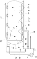
- a vehicle according to the invention comprises a pressure vessel 1, which is built on a chassis (not shown for reasons of clarity) and has two chambers 2, 3 with a partition wall 4, which in the upper region opens a passage opening 5 between the two chambers 2, 3.
- the chamber 2 is provided in the upper filling area with a vibrating screen 6, which protrudes with its overflow end 7 through the passage opening 5 of the partition 4 into the chamber 3.
- Additional chambers 9 separated from one another by partitions 8 can be connected to the chambers 2, 3.
- the chambers 2, 3 and 9 form discharge funnels 10, which are closed at the bottom by an emptying flap 11 and connected to a common delivery line 12.
- the pressure vessel 1 is pressurized by connecting it to the pressure side of the blower 13 via the pressure line 15.
- the pressure building up in the pressure vessel 1, after opening one of the emptying flaps 11, causes bulk material to be discharged through the discharge funnel 10 with the opened emptying flap 11 into the conveying line 12 and conveyed through the conveying line 12 with a conveying air flow.
- the conveying line 12 is connected to the pressure side of the blower 13 by a supply air line 18.
- compressed air can additionally be blown into the discharge funnel 10, specifically via lines 19.
- the fuel pellets are sucked together with the more fine-grained portion of pellet residues, dust and other impurities accumulating in the storage tank via the suction line 17 into the chamber 2, which is subjected to negative pressure via the suction line 14.
- the suctioned empties are separated from the conveying air flow via a cyclone separator 20 and reach the vibrating screen 6, along which the fuel pellets are separated from the screen passage and thrown into the chamber 3 via the overflow end 7, while the screen passage is collected in the chamber 2.
- the fuel pellets from the chamber 3 can then be discharged separately from the sieve passage through the conveyor line 12 and conveyed back to the storage facility.
- the sieve passage from the chamber 2 can also be discharged with the aid of the conveying line 12 and then possibly discarded.
- the emptied product contains an amount of fuel pellets that exceeds the capacity of the chamber 3, at least some of the fuel pellets can be conveyed from the chamber 3 into one of the additional chambers 9 in order to make room for the remaining amount of fuel pellets.
- the chambers 9 are usually used to transport fuel pellets to be supplied.
- chambers 2 and 3 can also be used for pellet delivery, it is advisable to move the vibrating sieve 6 from the drawn working position, in which it closes off a collecting space formed by the chamber 2 for the sieve passage, to a rest position in which it releases this collecting space so that the chamber 2 can be filled with fuel pellets to be supplied from above.
Landscapes
- Engineering & Computer Science (AREA)
- Health & Medical Sciences (AREA)
- Public Health (AREA)
- Transportation (AREA)
- Mechanical Engineering (AREA)
- Filling Or Emptying Of Bunkers, Hoppers, And Tanks (AREA)
Abstract
Description
- Die Erfindung bezieht sich auf ein Fahrzeug mit einem Druckbehälter zur Aufnahme von Brennstoffpellets, der wenigstens zwei wahlweise an die Druck- oder Saugseite eines Gebläses anschließbare Kammern mit je einem an eine Förderleitung angeschlossenen Austragstrichter umfasst.
- In Vorratslagern für Brennstoffpellets, üblicherweise Holzpellets, die aus dem Vorratslager mittels einer Fördereinrichtung einem Heizkessel zugeführt werden, sammeln sich im Laufe der Zeit Pelletsreste in Form von Bruchstücken und Staub sowie andere Verunreinigungen an, sodass diese Vorratslager von Zeit zu Zeit gereinigt werden müssen, was eine Entleerung der Vorratslager bedingt. Da in der Regel keine Vorrichtungen zum Trennen der Brennstoffpellets von den Pelletsresten und anderen Verunreinigungen zur Verfügung stehen, erfolgt die Reinigung der Vorratslager, wenn diese weitgehend geleert sind, um den Verlust an mit den Pelletsresten zu verwerfenden Brennstoffpellets klein zu halten.
- Zur Befüllung von Vorratslagern für Brennstoffpellets ist es bekannt, Fahrzeuge mit einem in einzelne Kammern unterteilten Druckbehälter einzusetzen. Die Brennstoffpellets werden mithilfe einer Ansaugleitung in die Kammern gefördert und über einen an eine Förderleitung angeschlossenen Austragstrichter ausgetragen. Zu diesem Zweck werden die Kammern entweder mit der Saug- oder der Druckseite eines Gebläses verbunden, sodass die jeweilige Kammer zum Ansaugen der Brennstoffpellets mit einem Unterdruck und zum Ausfördern der Brennstoffpellets mit einem Überdruck beaufschlagt werden kann. Mithilfe solcher Fahrzeuge könnte zwar eine vollständige Entleerung der Vorratslager durch ein Ansaugen der Brennstoffpellets und ihrer Reste in zumindest eine der Kammern des Druckbehälters vorgenommen werden, doch wird dadurch hinsichtlich der Wiedergewinnung der für die Beschickung eines Heizkessels noch geeigneten Brennstoffpellets nichts gewonnen.
- Der Erfindung liegt somit die Aufgabe zugrunde, eine einfache Möglichkeit zu schaffen, ein an eine Heizanlage angeschlossenes Vorratslager für Brennstoffpellets zu reinigen und mit den aus dem Entleergut gewonnenen Brennstoffpellets wieder zu befüllen.
- Ausgehend von einem Fahrzeug der eingangs beschriebenen Art löst die Erfindung die gestellte Aufgabe dadurch, dass eine der beiden Kammern ein über einen Zyklonabscheider mit Brennstoffpellets enthaltendem Schüttgut beschickbares Rüttelsieb aufweist, dessen Überlaufende in der anderen Kammer mündet.
- Durch diese Maßnahme gelangt das aus einem zu reinigenden Vorratsbehälter für Brennstoffpellets durch eine Ansaugleitung in die Kammer mit dem Rüttelsieb angesaugte Entleergut nach seiner Abscheidung aus dem Förderluftstrom auf das Rüttelsieb, mit dessen Hilfe die für die Beschickung des Heizkessels geeigneten Brennstoffpellets von den Pelletsresten, Staubanteilen und anderen Verunreinigungen getrennt werden. Die Loch- bzw. Maschenweite des Rüttelsiebs bestimmt dabei die Größe der zurückgehaltenen, wiederverwertbaren Brennstoffpellets.
- Während die Brennstoffpellets über das Überlaufende des Rüttelsiebs in die anschließende Kammer des Druckbehälters gefördert werden, wird der durch die Bruchstücke der Pellets und dem feinkörnigeren Anteil des Entleerguts gebildete Siebdurchgang in dem sich unterhalb des Rüttelsiebs ergebenden Auffangraum der Kammer gesammelt, um anschließend ausgetragen zu werden. Der Unterdruck in der Kammer unterhalb des Rüttelsiebs unterstützt dabei den Durchtritt des feinkörnigeren Entleerguts durch das Rüttelsieb. Es muss allerdings dafür gesorgt werden, dass die vom Gebläse angesaugte Luft weitgehend staubfrei ist, was durch geeignete Filter in einfacher Weise sichergestellt werden kann. Aus der das Überlaufende des Rüttelsiebs aufnehmenden Kammer können die gesammelten Brennstoffpellets über den Austragstrichter ausgetragen und mithilfe der Förderleitung wieder in das Vorratslager gefördert werden.
- Damit die Kammer des Druckbehälters mit dem Rüttelsieb nicht nur für die Pelletsreinigung, sondern auch für die Lieferung von Brennstoffpellets genützt werden kann, kann das Rüttelsieb zwischen einer einen Auffangraum für den Siebdurchgang nach oben abschließenden Arbeitsstellung und einer diesen Auffangraum freigebenden Ruhestellung verlagert werden, beispielsweise mithilfe einer Schwenklagerung des Rüttelsiebs.
- Umfasst der Druckbehälter zumindest eine weitere Kammer mit einem an die Förderleitung anschließbaren Austragstrichter, so kann diese zusätzliche Kammer für die Lieferung von Brennstoffpellets genützt werden, ohne auf die Reinigungsfunktion der beiden anderen Kammern verzichten zu müssen. Die zusätzliche Kammer des Druckbehälters erlaubt außerdem ein Umladen der die gereinigten Brennstoffpellets aufnehmenden Kammer, wenn die Menge der wiederverwertbaren Brennstoffpellets des Entleerguts das Aufnahmevolumen dieser Kammer übersteigt.
- In der Zeichnung ist der Erfindungsgegenstand beispielsweise dargestellt, und zwar wird ein erfindungsgemäßes Fahrzeug in einem schematischen Blockschaltbild gezeigt.
- Ein erfindungsgemäßes Fahrzeug umfasst einen auf einem aus Übersichtlichkeitsgründen nicht dargestellten Fahrgestell aufgebauten Druckbehälter 1, der zwei Kammern 2, 3 mit einer Trennwand 4 aufweist, die im oberen Bereich eine Durchtrittsöffnung 5 zwischen den beiden Kammern 2, 3 freigibt. Die Kammer 2 ist im oberen Einfüllbereich mit einem Rüttelsieb 6 versehen, das mit seinem Überlaufende 7 durch die Durchtrittsöffnung 5 der Trennwand 4 in die Kammer 3 ragt. An die Kammern 2, 3 können sich durch Trennwände 8 voneinander getrennte zusätzliche Kammern 9 anschließen. Die Kammern 2, 3 und 9 bilden Austragstrichter 10, die nach unten durch eine Entleerklappe 11 abgeschlossen und an eine gemeinsame Förderleitung 12 angeschlossen sind.
- Zur Druckbeaufschlagung des Druckbehälters 1 dient eine Gebläse 13, vorzugsweise ein Drehkolbengebläse, das von einem Nebenantrieb des Fahrzeugs angetrieben und wahlweise durch eine Saugleitung 14 oder durch eine Druckleitung 15 mit dem Druckbehälter 1 verbunden wird. Wird der Druckbehälter 1 durch die über ein Filter 16 in den Druckbehälter 1 mündende Saugleitung 14 mit Unterdruck beaufschlagt, so kann der Druckbehälter 1 mithilfe einer Ansaugleitung 17 beladen werden, durch die Schüttgut zufolge des im Druckbehälter 1 herrschenden Unterdrucks in den Druckbehälter 1 angesaugt wird.
- Zum Austragen von Schüttgut wird der Druckbehälter 1 mit Überdruck beaufschlagt, indem er über die Druckleitung 15 mit der Druckseite des Gebläses 13 verbunden wird. Der sich im Druckbehälter 1 aufbauende Druck bewirkt nach dem Öffnen einer der Entleerklappen 11, dass Schüttgut durch den Austragstrichter 10 mit der geöffneten Entleerklappe 11 in die Förderleitung 12 ausgetragen und mit einem Förderluftstrom durch die Förderleitung 12 gefördert wird. Um im Bedarfsfall ausreichend Förderluft für die Schüttgutförderung durch die Förderleitung 12 zur Verfügung stellen zu können, ist die Förderleitung 12 mit der Druckseite des Gebläses 13 durch eine Zuluftleitung 18 verbunden. Um Brückenbildungen im Schüttgut innerhalb der Austragstrichter 10 zu vermeiden, kann zusätzlich Druckluft in die Austragstrichter 10 eingeblasen werden, und zwar über Leitungen 19.
- Die entsprechenden Leitungsverbindungen sind aus Übersichtlichkeitsgründen lediglich für die Kammern 2 und 3 gezeichnet. Die Kammern 9 sind analog in bekannter Weise an das Sauggebläse 13 angeschlossen.
- Zur Reinigung von Vorratslagern für Brennstoffpellets werden die Brennstoffpellets zusammen mit dem sich im Vorratslager ansammelnden feinkörnigeren Anteil aus Pelletsresten, Staub und anderen Verunreinigungen über die Ansaugleitung 17 in die Kammer 2 angesaugt, die über die Saugleitung 14 mit Unterdruck beaufschlagt wird. das angesaugte Entleergut wird über einen Zyklonabscheider 20 aus dem Förderluftstrom abgetrennt und gelangt auf das Rüttelsieb 6, entlang dessen die Brennstoffpellets vom Siebdurchgang getrennt und über das Überlaufende 7 in die Kammer 3 abgeworfen werden, während der Siebdurchgang in der Kammer 2 gesammelt wird. Die Brennstoffpellets aus der Kammer 3 können dann getrennt vom Siebdurchgang durch die Förderleitung 12 ausgetragen und in das Vorratslager zurückgefördert werden. Der Siebdurchgang aus der Kammer 2 kann ebenfalls mithilfe der Förderleitung 12 ausgetragen und dann gegebenenfalls verworfen werden.
- Enthält das Entleergut eine das Fassungsvermögen der Kammer 3 übersteigende Menge an Brennstoffpellets, kann zumindest ein Teil der Brennstoffpellets aus der Kammer 3 in eine der zusätzlichen Kammern 9 gefördert werden, um Platz für die Restmenge an Brennstoffpellets zu schaffen. Die Kammern 9 dienen üblicherweise zum Transport von zu liefernden Brennstoffpellets.
- Damit auch die Kammern 2 und 3 zur Pelletslieferung genützt werden können, empfiehlt es sich, das Rüttelsieb 6 aus der gezeichneten Arbeitsstellung, in der es einen durch die Kammer 2 gebildeten Auffangraum für den Siebdurchgang nach oben abschließt, in eine Ruhestellung zu verlagern, in der es diesen Auffangraum freigibt, sodass die Kammer 2 von oben mit zu liefernden Brennstoffpellets gefüllt werden kann.
Claims (3)
- Fahrzeug mit einem Druckbehälter (1) zur Aufnahme von Brennstoffpellets, der wenigstens zwei wahlweise an die Druck- oder Saugseite eines Gebläses (13) anschließbare Kammern (2, 3) mit je einem an eine Förderleitung (12) angeschlossenen Austragstrichter (10) umfasst, dadurch gekennzeichnet, dass eine der beiden Kammern (2, 3) ein über einen Zyklonabscheider (20) mit Brennstoffpellets enthaltendem Schüttgut beschickbares Rüttelsieb (6) aufweist, dessen Überlaufende (7) in der anderen Kammer (3) mündet.
- Fahrzeug nach Anspruch 1, dadurch gekennzeichnet, dass das Rüttelsieb (6) zwischen einer einen Auffangraum für den Siebdurchgang nach oben abschließenden Arbeitsstellung und einer diesen Auffangraum freigebenden Ruhestellung verlagerbar ist.
- Fahrzeug nach Anspruch 1 oder 2, dadurch gekennzeichnet, dass der Druckbehälter (1) zumindest eine weitere Kammer (9) mit einem an die Förderleitung (12) anschließbaren Austragstrichter (10) umfasst.
Applications Claiming Priority (1)
| Application Number | Priority Date | Filing Date | Title |
|---|---|---|---|
| ATA50668/2018A AT521045B1 (de) | 2018-08-01 | 2018-08-01 | Fahrzeug mit einem Druckbehälter zur Aufnahme von Brennstoffpellets |
Publications (2)
| Publication Number | Publication Date |
|---|---|
| EP3604034A1 true EP3604034A1 (de) | 2020-02-05 |
| EP3604034B1 EP3604034B1 (de) | 2021-02-17 |
Family
ID=67383709
Family Applications (1)
| Application Number | Title | Priority Date | Filing Date |
|---|---|---|---|
| EP19185197.1A Active EP3604034B1 (de) | 2018-08-01 | 2019-07-09 | Fahrzeug mit einem druckbehälter zur aufnahme von brennstoffpellets |
Country Status (2)
| Country | Link |
|---|---|
| EP (1) | EP3604034B1 (de) |
| AT (1) | AT521045B1 (de) |
Cited By (1)
| Publication number | Priority date | Publication date | Assignee | Title |
|---|---|---|---|---|
| CN120482669A (zh) * | 2025-07-18 | 2025-08-15 | 江苏春海电热合金制造有限公司 | 一种电阻合金带运输设备 |
Citations (3)
| Publication number | Priority date | Publication date | Assignee | Title |
|---|---|---|---|---|
| GB963343A (en) * | 1962-05-28 | 1964-07-08 | Murfitt Bulk Transp Ers Ltd | Improvements in or relating to bulk transporting vehicles |
| DE102008019995A1 (de) * | 2007-04-24 | 2008-10-30 | Tropper Maschinen Und Anlagen Gmbh | Fahrzeug mit einem Mischbehälter |
| DE202018100113U1 (de) * | 2017-07-10 | 2018-01-25 | Tropper Maschinen Und Anlagen Gmbh | Silofahrzeug für Schüttgut |
Family Cites Families (1)
| Publication number | Priority date | Publication date | Assignee | Title |
|---|---|---|---|---|
| DE1555676C3 (de) * | 1964-08-25 | 1978-06-08 | Wilhelm 5050 Porz Hermanns | Behälterfahrzeug für Schüttgut |
-
2018
- 2018-08-01 AT ATA50668/2018A patent/AT521045B1/de not_active IP Right Cessation
-
2019
- 2019-07-09 EP EP19185197.1A patent/EP3604034B1/de active Active
Patent Citations (3)
| Publication number | Priority date | Publication date | Assignee | Title |
|---|---|---|---|---|
| GB963343A (en) * | 1962-05-28 | 1964-07-08 | Murfitt Bulk Transp Ers Ltd | Improvements in or relating to bulk transporting vehicles |
| DE102008019995A1 (de) * | 2007-04-24 | 2008-10-30 | Tropper Maschinen Und Anlagen Gmbh | Fahrzeug mit einem Mischbehälter |
| DE202018100113U1 (de) * | 2017-07-10 | 2018-01-25 | Tropper Maschinen Und Anlagen Gmbh | Silofahrzeug für Schüttgut |
Cited By (1)
| Publication number | Priority date | Publication date | Assignee | Title |
|---|---|---|---|---|
| CN120482669A (zh) * | 2025-07-18 | 2025-08-15 | 江苏春海电热合金制造有限公司 | 一种电阻合金带运输设备 |
Also Published As
| Publication number | Publication date |
|---|---|
| AT521045B1 (de) | 2019-10-15 |
| AT521045A4 (de) | 2019-10-15 |
| EP3604034B1 (de) | 2021-02-17 |
Similar Documents
| Publication | Publication Date | Title |
|---|---|---|
| EP0039694B1 (de) | Fahrzeug mit kehrmaschine, insbesondere zum einholen von staubförmigen material und deren verwendung | |
| DE3017071A1 (de) | Vakuum-materialtransportsystem | |
| DE60000348T2 (de) | Anlage zum entfernen von streu und zum wiederfüllen von tierkäfigen | |
| DE3686542T2 (de) | System zur wiederverwertung von abstaubmehl. | |
| DE2437799A1 (de) | Pneumatische foerdervorrichtung fuer staubfoermiges oder koerniges gut mit mindestens einer absaugeinrichtung | |
| EP1427657B1 (de) | Vorrichtung und verfahren zum überführen eines staub-, pulver-, korn- oder granulatartigen fördergutes aus einem lagerbehälter in einen arbeits- oder überführungsbehälter od.dgl. aufnahmeraum | |
| EP3604034B1 (de) | Fahrzeug mit einem druckbehälter zur aufnahme von brennstoffpellets | |
| DE102012216031B4 (de) | System, Tabaksendevorrichtung und Verfahren zum Fördern von feuchtem zerkleinerten Tabakmaterial | |
| DE1903906A1 (de) | Verfahren und Vorrichtung fuer Absaugefoerderung von Muell u.dgl. | |
| DE3007345A1 (de) | Absauggeraet, insbesondere fuer gewerbliche oder industrielle zwecke | |
| DE2308404B2 (de) | Foerdereinrichtung zum foerdern und abscheiden eines foerdergurtes | |
| DE255849C (de) | ||
| AT503944B1 (de) | Fahrzeug zum sammeln von küchenabfällen | |
| DE3027683C2 (de) | ||
| DE19634291C2 (de) | Vorrichtung zum Sieben | |
| DE3127481A1 (de) | Vorrichtung zum entleeren von dragierkesseln und zum nachtrocknen und zwischenlagern von dragees | |
| DE102006061256B4 (de) | Filteranlage zum Abscheiden von Stäuben aus Gasen | |
| EP0040389B1 (de) | Verfahren zum Entleeren von transportablen Behältern für feinkörniges Transportgut | |
| DE8814399U1 (de) | Vorabscheider mit Ringspülleitungen zur Abscheidung und Ausspülung von feinstfaserförmigen Schadstoffen | |
| DE102018007620B4 (de) | Verfahren und System zum Verwerten von biologischem Abfall | |
| DE102023112327A1 (de) | Beladeverfahren für eine Mischvorrichtung mit Entlüftungssystem und Mischvorrichtung | |
| DE266400C (de) | ||
| DE4203495A1 (de) | Sackentleervorrichtung und verfahren zum betrieb und reinigen derselben | |
| CH376429A (de) | Silo-Anlage für staubartiges oder feinkörniges Gut mit einer Einrichtung zum Mischen und Fördern des Gutes | |
| DE10338878B4 (de) | Verfahren zum Sammeln der Asche von Einäscherungsvorgängen |
Legal Events
| Date | Code | Title | Description |
|---|---|---|---|
| PUAI | Public reference made under article 153(3) epc to a published international application that has entered the european phase |
Free format text: ORIGINAL CODE: 0009012 |
|
| STAA | Information on the status of an ep patent application or granted ep patent |
Free format text: STATUS: THE APPLICATION HAS BEEN PUBLISHED |
|
| AK | Designated contracting states |
Kind code of ref document: A1 Designated state(s): AL AT BE BG CH CY CZ DE DK EE ES FI FR GB GR HR HU IE IS IT LI LT LU LV MC MK MT NL NO PL PT RO RS SE SI SK SM TR |
|
| AX | Request for extension of the european patent |
Extension state: BA ME |
|
| STAA | Information on the status of an ep patent application or granted ep patent |
Free format text: STATUS: REQUEST FOR EXAMINATION WAS MADE |
|
| 17P | Request for examination filed |
Effective date: 20200708 |
|
| RBV | Designated contracting states (corrected) |
Designated state(s): AL AT BE BG CH CY CZ DE DK EE ES FI FR GB GR HR HU IE IS IT LI LT LU LV MC MK MT NL NO PL PT RO RS SE SI SK SM TR |
|
| GRAP | Despatch of communication of intention to grant a patent |
Free format text: ORIGINAL CODE: EPIDOSNIGR1 |
|
| STAA | Information on the status of an ep patent application or granted ep patent |
Free format text: STATUS: GRANT OF PATENT IS INTENDED |
|
| RIC1 | Information provided on ipc code assigned before grant |
Ipc: B65G 53/16 20060101ALI20201021BHEP Ipc: B65D 88/72 20060101ALI20201021BHEP Ipc: B60P 3/22 20060101AFI20201021BHEP |
|
| INTG | Intention to grant announced |
Effective date: 20201119 |
|
| GRAS | Grant fee paid |
Free format text: ORIGINAL CODE: EPIDOSNIGR3 |
|
| GRAA | (expected) grant |
Free format text: ORIGINAL CODE: 0009210 |
|
| STAA | Information on the status of an ep patent application or granted ep patent |
Free format text: STATUS: THE PATENT HAS BEEN GRANTED |
|
| AK | Designated contracting states |
Kind code of ref document: B1 Designated state(s): AL AT BE BG CH CY CZ DE DK EE ES FI FR GB GR HR HU IE IS IT LI LT LU LV MC MK MT NL NO PL PT RO RS SE SI SK SM TR |
|
| RAP1 | Party data changed (applicant data changed or rights of an application transferred) |
Owner name: TROPPER MASCHINEN UND ANLAGEN GMBH. |
|
| REG | Reference to a national code |
Ref country code: GB Ref legal event code: FG4D Free format text: NOT ENGLISH |
|
| REG | Reference to a national code |
Ref country code: CH Ref legal event code: EP |
|
| REG | Reference to a national code |
Ref country code: DE Ref legal event code: R096 Ref document number: 502019000807 Country of ref document: DE |
|
| REG | Reference to a national code |
Ref country code: AT Ref legal event code: REF Ref document number: 1361056 Country of ref document: AT Kind code of ref document: T Effective date: 20210315 |
|
| REG | Reference to a national code |
Ref country code: IE Ref legal event code: FG4D Free format text: LANGUAGE OF EP DOCUMENT: GERMAN |
|
| REG | Reference to a national code |
Ref country code: CH Ref legal event code: NV Representative=s name: E. BLUM AND CO. AG PATENT- UND MARKENANWAELTE V, CH |
|
| REG | Reference to a national code |
Ref country code: LT Ref legal event code: MG9D |
|
| REG | Reference to a national code |
Ref country code: NL Ref legal event code: MP Effective date: 20210217 |
|
| PG25 | Lapsed in a contracting state [announced via postgrant information from national office to epo] |
Ref country code: GR Free format text: LAPSE BECAUSE OF FAILURE TO SUBMIT A TRANSLATION OF THE DESCRIPTION OR TO PAY THE FEE WITHIN THE PRESCRIBED TIME-LIMIT Effective date: 20210518 Ref country code: FI Free format text: LAPSE BECAUSE OF FAILURE TO SUBMIT A TRANSLATION OF THE DESCRIPTION OR TO PAY THE FEE WITHIN THE PRESCRIBED TIME-LIMIT Effective date: 20210217 Ref country code: HR Free format text: LAPSE BECAUSE OF FAILURE TO SUBMIT A TRANSLATION OF THE DESCRIPTION OR TO PAY THE FEE WITHIN THE PRESCRIBED TIME-LIMIT Effective date: 20210217 Ref country code: BG Free format text: LAPSE BECAUSE OF FAILURE TO SUBMIT A TRANSLATION OF THE DESCRIPTION OR TO PAY THE FEE WITHIN THE PRESCRIBED TIME-LIMIT Effective date: 20210517 Ref country code: NO Free format text: LAPSE BECAUSE OF FAILURE TO SUBMIT A TRANSLATION OF THE DESCRIPTION OR TO PAY THE FEE WITHIN THE PRESCRIBED TIME-LIMIT Effective date: 20210517 Ref country code: PT Free format text: LAPSE BECAUSE OF FAILURE TO SUBMIT A TRANSLATION OF THE DESCRIPTION OR TO PAY THE FEE WITHIN THE PRESCRIBED TIME-LIMIT Effective date: 20210617 Ref country code: LT Free format text: LAPSE BECAUSE OF FAILURE TO SUBMIT A TRANSLATION OF THE DESCRIPTION OR TO PAY THE FEE WITHIN THE PRESCRIBED TIME-LIMIT Effective date: 20210217 |
|
| PG25 | Lapsed in a contracting state [announced via postgrant information from national office to epo] |
Ref country code: NL Free format text: LAPSE BECAUSE OF FAILURE TO SUBMIT A TRANSLATION OF THE DESCRIPTION OR TO PAY THE FEE WITHIN THE PRESCRIBED TIME-LIMIT Effective date: 20210217 Ref country code: LV Free format text: LAPSE BECAUSE OF FAILURE TO SUBMIT A TRANSLATION OF THE DESCRIPTION OR TO PAY THE FEE WITHIN THE PRESCRIBED TIME-LIMIT Effective date: 20210217 Ref country code: PL Free format text: LAPSE BECAUSE OF FAILURE TO SUBMIT A TRANSLATION OF THE DESCRIPTION OR TO PAY THE FEE WITHIN THE PRESCRIBED TIME-LIMIT Effective date: 20210217 Ref country code: SE Free format text: LAPSE BECAUSE OF FAILURE TO SUBMIT A TRANSLATION OF THE DESCRIPTION OR TO PAY THE FEE WITHIN THE PRESCRIBED TIME-LIMIT Effective date: 20210217 Ref country code: RS Free format text: LAPSE BECAUSE OF FAILURE TO SUBMIT A TRANSLATION OF THE DESCRIPTION OR TO PAY THE FEE WITHIN THE PRESCRIBED TIME-LIMIT Effective date: 20210217 |
|
| PG25 | Lapsed in a contracting state [announced via postgrant information from national office to epo] |
Ref country code: IS Free format text: LAPSE BECAUSE OF FAILURE TO SUBMIT A TRANSLATION OF THE DESCRIPTION OR TO PAY THE FEE WITHIN THE PRESCRIBED TIME-LIMIT Effective date: 20210617 |
|
| PG25 | Lapsed in a contracting state [announced via postgrant information from national office to epo] |
Ref country code: CZ Free format text: LAPSE BECAUSE OF FAILURE TO SUBMIT A TRANSLATION OF THE DESCRIPTION OR TO PAY THE FEE WITHIN THE PRESCRIBED TIME-LIMIT Effective date: 20210217 Ref country code: EE Free format text: LAPSE BECAUSE OF FAILURE TO SUBMIT A TRANSLATION OF THE DESCRIPTION OR TO PAY THE FEE WITHIN THE PRESCRIBED TIME-LIMIT Effective date: 20210217 Ref country code: SM Free format text: LAPSE BECAUSE OF FAILURE TO SUBMIT A TRANSLATION OF THE DESCRIPTION OR TO PAY THE FEE WITHIN THE PRESCRIBED TIME-LIMIT Effective date: 20210217 |
|
| REG | Reference to a national code |
Ref country code: DE Ref legal event code: R097 Ref document number: 502019000807 Country of ref document: DE |
|
| PG25 | Lapsed in a contracting state [announced via postgrant information from national office to epo] |
Ref country code: DK Free format text: LAPSE BECAUSE OF FAILURE TO SUBMIT A TRANSLATION OF THE DESCRIPTION OR TO PAY THE FEE WITHIN THE PRESCRIBED TIME-LIMIT Effective date: 20210217 Ref country code: RO Free format text: LAPSE BECAUSE OF FAILURE TO SUBMIT A TRANSLATION OF THE DESCRIPTION OR TO PAY THE FEE WITHIN THE PRESCRIBED TIME-LIMIT Effective date: 20210217 Ref country code: SK Free format text: LAPSE BECAUSE OF FAILURE TO SUBMIT A TRANSLATION OF THE DESCRIPTION OR TO PAY THE FEE WITHIN THE PRESCRIBED TIME-LIMIT Effective date: 20210217 |
|
| PLBE | No opposition filed within time limit |
Free format text: ORIGINAL CODE: 0009261 |
|
| STAA | Information on the status of an ep patent application or granted ep patent |
Free format text: STATUS: NO OPPOSITION FILED WITHIN TIME LIMIT |
|
| 26N | No opposition filed |
Effective date: 20211118 |
|
| PG25 | Lapsed in a contracting state [announced via postgrant information from national office to epo] |
Ref country code: AL Free format text: LAPSE BECAUSE OF FAILURE TO SUBMIT A TRANSLATION OF THE DESCRIPTION OR TO PAY THE FEE WITHIN THE PRESCRIBED TIME-LIMIT Effective date: 20210217 Ref country code: ES Free format text: LAPSE BECAUSE OF FAILURE TO SUBMIT A TRANSLATION OF THE DESCRIPTION OR TO PAY THE FEE WITHIN THE PRESCRIBED TIME-LIMIT Effective date: 20210217 |
|
| PG25 | Lapsed in a contracting state [announced via postgrant information from national office to epo] |
Ref country code: SI Free format text: LAPSE BECAUSE OF FAILURE TO SUBMIT A TRANSLATION OF THE DESCRIPTION OR TO PAY THE FEE WITHIN THE PRESCRIBED TIME-LIMIT Effective date: 20210217 |
|
| PG25 | Lapsed in a contracting state [announced via postgrant information from national office to epo] |
Ref country code: MC Free format text: LAPSE BECAUSE OF FAILURE TO SUBMIT A TRANSLATION OF THE DESCRIPTION OR TO PAY THE FEE WITHIN THE PRESCRIBED TIME-LIMIT Effective date: 20210217 |
|
| REG | Reference to a national code |
Ref country code: BE Ref legal event code: MM Effective date: 20210731 |
|
| PG25 | Lapsed in a contracting state [announced via postgrant information from national office to epo] |
Ref country code: IT Free format text: LAPSE BECAUSE OF FAILURE TO SUBMIT A TRANSLATION OF THE DESCRIPTION OR TO PAY THE FEE WITHIN THE PRESCRIBED TIME-LIMIT Effective date: 20210217 |
|
| PG25 | Lapsed in a contracting state [announced via postgrant information from national office to epo] |
Ref country code: IS Free format text: LAPSE BECAUSE OF FAILURE TO SUBMIT A TRANSLATION OF THE DESCRIPTION OR TO PAY THE FEE WITHIN THE PRESCRIBED TIME-LIMIT Effective date: 20210617 Ref country code: LU Free format text: LAPSE BECAUSE OF NON-PAYMENT OF DUE FEES Effective date: 20210709 Ref country code: FR Free format text: LAPSE BECAUSE OF NON-PAYMENT OF DUE FEES Effective date: 20210731 |
|
| PG25 | Lapsed in a contracting state [announced via postgrant information from national office to epo] |
Ref country code: IE Free format text: LAPSE BECAUSE OF NON-PAYMENT OF DUE FEES Effective date: 20210709 Ref country code: BE Free format text: LAPSE BECAUSE OF NON-PAYMENT OF DUE FEES Effective date: 20210731 |
|
| P01 | Opt-out of the competence of the unified patent court (upc) registered |
Effective date: 20230506 |
|
| PG25 | Lapsed in a contracting state [announced via postgrant information from national office to epo] |
Ref country code: CY Free format text: LAPSE BECAUSE OF FAILURE TO SUBMIT A TRANSLATION OF THE DESCRIPTION OR TO PAY THE FEE WITHIN THE PRESCRIBED TIME-LIMIT Effective date: 20210217 |
|
| PG25 | Lapsed in a contracting state [announced via postgrant information from national office to epo] |
Ref country code: HU Free format text: LAPSE BECAUSE OF FAILURE TO SUBMIT A TRANSLATION OF THE DESCRIPTION OR TO PAY THE FEE WITHIN THE PRESCRIBED TIME-LIMIT; INVALID AB INITIO Effective date: 20190709 |
|
| GBPC | Gb: european patent ceased through non-payment of renewal fee |
Effective date: 20230709 |
|
| PG25 | Lapsed in a contracting state [announced via postgrant information from national office to epo] |
Ref country code: MK Free format text: LAPSE BECAUSE OF FAILURE TO SUBMIT A TRANSLATION OF THE DESCRIPTION OR TO PAY THE FEE WITHIN THE PRESCRIBED TIME-LIMIT Effective date: 20210217 Ref country code: GB Free format text: LAPSE BECAUSE OF NON-PAYMENT OF DUE FEES Effective date: 20230709 |
|
| PG25 | Lapsed in a contracting state [announced via postgrant information from national office to epo] |
Ref country code: MT Free format text: LAPSE BECAUSE OF FAILURE TO SUBMIT A TRANSLATION OF THE DESCRIPTION OR TO PAY THE FEE WITHIN THE PRESCRIBED TIME-LIMIT Effective date: 20210217 |
|
| PGFP | Annual fee paid to national office [announced via postgrant information from national office to epo] |
Ref country code: DE Payment date: 20250715 Year of fee payment: 7 |
|
| PGFP | Annual fee paid to national office [announced via postgrant information from national office to epo] |
Ref country code: AT Payment date: 20250715 Year of fee payment: 7 |
|
| PGFP | Annual fee paid to national office [announced via postgrant information from national office to epo] |
Ref country code: CH Payment date: 20250801 Year of fee payment: 7 |
|
| PG25 | Lapsed in a contracting state [announced via postgrant information from national office to epo] |
Ref country code: TR Free format text: LAPSE BECAUSE OF FAILURE TO SUBMIT A TRANSLATION OF THE DESCRIPTION OR TO PAY THE FEE WITHIN THE PRESCRIBED TIME-LIMIT Effective date: 20210217 |