EP3603735B1 - Rohrverbindungsvorrichtung - Google Patents
Rohrverbindungsvorrichtung Download PDFInfo
- Publication number
- EP3603735B1 EP3603735B1 EP18772245.9A EP18772245A EP3603735B1 EP 3603735 B1 EP3603735 B1 EP 3603735B1 EP 18772245 A EP18772245 A EP 18772245A EP 3603735 B1 EP3603735 B1 EP 3603735B1
- Authority
- EP
- European Patent Office
- Prior art keywords
- tube
- pressing member
- joining
- holding portion
- tubes
- Prior art date
- Legal status (The legal status is an assumption and is not a legal conclusion. Google has not performed a legal analysis and makes no representation as to the accuracy of the status listed.)
- Active
Links
Images


Classifications
-
- B—PERFORMING OPERATIONS; TRANSPORTING
- B29—WORKING OF PLASTICS; WORKING OF SUBSTANCES IN A PLASTIC STATE IN GENERAL
- B29C—SHAPING OR JOINING OF PLASTICS; SHAPING OF MATERIAL IN A PLASTIC STATE, NOT OTHERWISE PROVIDED FOR; AFTER-TREATMENT OF THE SHAPED PRODUCTS, e.g. REPAIRING
- B29C65/00—Joining or sealing of preformed parts, e.g. welding of plastics materials; Apparatus therefor
- B29C65/02—Joining or sealing of preformed parts, e.g. welding of plastics materials; Apparatus therefor by heating, with or without pressure
- B29C65/18—Joining or sealing of preformed parts, e.g. welding of plastics materials; Apparatus therefor by heating, with or without pressure using heated tools
- B29C65/20—Joining or sealing of preformed parts, e.g. welding of plastics materials; Apparatus therefor by heating, with or without pressure using heated tools with direct contact, e.g. using "mirror"
- B29C65/2046—Joining or sealing of preformed parts, e.g. welding of plastics materials; Apparatus therefor by heating, with or without pressure using heated tools with direct contact, e.g. using "mirror" using a welding mirror which also cuts the parts to be joined, e.g. for sterile welding
-
- A—HUMAN NECESSITIES
- A61—MEDICAL OR VETERINARY SCIENCE; HYGIENE
- A61M—DEVICES FOR INTRODUCING MEDIA INTO, OR ONTO, THE BODY; DEVICES FOR TRANSDUCING BODY MEDIA OR FOR TAKING MEDIA FROM THE BODY; DEVICES FOR PRODUCING OR ENDING SLEEP OR STUPOR
- A61M39/00—Tubes, tube connectors, tube couplings, valves, access sites or the like, specially adapted for medical use
- A61M39/10—Tube connectors; Tube couplings
- A61M39/14—Tube connectors; Tube couplings for connecting tubes having sealed ends
- A61M39/146—Tube connectors; Tube couplings for connecting tubes having sealed ends by cutting and welding
-
- B—PERFORMING OPERATIONS; TRANSPORTING
- B29—WORKING OF PLASTICS; WORKING OF SUBSTANCES IN A PLASTIC STATE IN GENERAL
- B29C—SHAPING OR JOINING OF PLASTICS; SHAPING OF MATERIAL IN A PLASTIC STATE, NOT OTHERWISE PROVIDED FOR; AFTER-TREATMENT OF THE SHAPED PRODUCTS, e.g. REPAIRING
- B29C65/00—Joining or sealing of preformed parts, e.g. welding of plastics materials; Apparatus therefor
- B29C65/02—Joining or sealing of preformed parts, e.g. welding of plastics materials; Apparatus therefor by heating, with or without pressure
- B29C65/18—Joining or sealing of preformed parts, e.g. welding of plastics materials; Apparatus therefor by heating, with or without pressure using heated tools
- B29C65/20—Joining or sealing of preformed parts, e.g. welding of plastics materials; Apparatus therefor by heating, with or without pressure using heated tools with direct contact, e.g. using "mirror"
- B29C65/2007—Joining or sealing of preformed parts, e.g. welding of plastics materials; Apparatus therefor by heating, with or without pressure using heated tools with direct contact, e.g. using "mirror" characterised by the type of welding mirror
- B29C65/203—Joining or sealing of preformed parts, e.g. welding of plastics materials; Apparatus therefor by heating, with or without pressure using heated tools with direct contact, e.g. using "mirror" characterised by the type of welding mirror being several single mirrors, e.g. not mounted on the same tool
-
- B—PERFORMING OPERATIONS; TRANSPORTING
- B29—WORKING OF PLASTICS; WORKING OF SUBSTANCES IN A PLASTIC STATE IN GENERAL
- B29C—SHAPING OR JOINING OF PLASTICS; SHAPING OF MATERIAL IN A PLASTIC STATE, NOT OTHERWISE PROVIDED FOR; AFTER-TREATMENT OF THE SHAPED PRODUCTS, e.g. REPAIRING
- B29C65/00—Joining or sealing of preformed parts, e.g. welding of plastics materials; Apparatus therefor
- B29C65/02—Joining or sealing of preformed parts, e.g. welding of plastics materials; Apparatus therefor by heating, with or without pressure
- B29C65/18—Joining or sealing of preformed parts, e.g. welding of plastics materials; Apparatus therefor by heating, with or without pressure using heated tools
- B29C65/20—Joining or sealing of preformed parts, e.g. welding of plastics materials; Apparatus therefor by heating, with or without pressure using heated tools with direct contact, e.g. using "mirror"
- B29C65/2053—Joining or sealing of preformed parts, e.g. welding of plastics materials; Apparatus therefor by heating, with or without pressure using heated tools with direct contact, e.g. using "mirror" characterised by special ways of bringing the welding mirrors into position
- B29C65/2061—Joining or sealing of preformed parts, e.g. welding of plastics materials; Apparatus therefor by heating, with or without pressure using heated tools with direct contact, e.g. using "mirror" characterised by special ways of bringing the welding mirrors into position by sliding
- B29C65/2069—Joining or sealing of preformed parts, e.g. welding of plastics materials; Apparatus therefor by heating, with or without pressure using heated tools with direct contact, e.g. using "mirror" characterised by special ways of bringing the welding mirrors into position by sliding with an angle with respect to the plane comprising the parts to be joined
- B29C65/2076—Joining or sealing of preformed parts, e.g. welding of plastics materials; Apparatus therefor by heating, with or without pressure using heated tools with direct contact, e.g. using "mirror" characterised by special ways of bringing the welding mirrors into position by sliding with an angle with respect to the plane comprising the parts to be joined perpendicularly to the plane comprising the parts to be joined
-
- B—PERFORMING OPERATIONS; TRANSPORTING
- B29—WORKING OF PLASTICS; WORKING OF SUBSTANCES IN A PLASTIC STATE IN GENERAL
- B29C—SHAPING OR JOINING OF PLASTICS; SHAPING OF MATERIAL IN A PLASTIC STATE, NOT OTHERWISE PROVIDED FOR; AFTER-TREATMENT OF THE SHAPED PRODUCTS, e.g. REPAIRING
- B29C65/00—Joining or sealing of preformed parts, e.g. welding of plastics materials; Apparatus therefor
- B29C65/02—Joining or sealing of preformed parts, e.g. welding of plastics materials; Apparatus therefor by heating, with or without pressure
- B29C65/18—Joining or sealing of preformed parts, e.g. welding of plastics materials; Apparatus therefor by heating, with or without pressure using heated tools
- B29C65/24—Joining or sealing of preformed parts, e.g. welding of plastics materials; Apparatus therefor by heating, with or without pressure using heated tools characterised by the means for heating the tool
- B29C65/30—Electrical means
-
- B—PERFORMING OPERATIONS; TRANSPORTING
- B29—WORKING OF PLASTICS; WORKING OF SUBSTANCES IN A PLASTIC STATE IN GENERAL
- B29C—SHAPING OR JOINING OF PLASTICS; SHAPING OF MATERIAL IN A PLASTIC STATE, NOT OTHERWISE PROVIDED FOR; AFTER-TREATMENT OF THE SHAPED PRODUCTS, e.g. REPAIRING
- B29C65/00—Joining or sealing of preformed parts, e.g. welding of plastics materials; Apparatus therefor
- B29C65/74—Joining or sealing of preformed parts, e.g. welding of plastics materials; Apparatus therefor by welding and severing, or by joining and severing, the severing being performed in the area to be joined, next to the area to be joined, in the joint area or next to the joint area
- B29C65/743—Joining or sealing of preformed parts, e.g. welding of plastics materials; Apparatus therefor by welding and severing, or by joining and severing, the severing being performed in the area to be joined, next to the area to be joined, in the joint area or next to the joint area using the same tool for both joining and severing, said tool being monobloc or formed by several parts mounted together and forming a monobloc
-
- B—PERFORMING OPERATIONS; TRANSPORTING
- B29—WORKING OF PLASTICS; WORKING OF SUBSTANCES IN A PLASTIC STATE IN GENERAL
- B29C—SHAPING OR JOINING OF PLASTICS; SHAPING OF MATERIAL IN A PLASTIC STATE, NOT OTHERWISE PROVIDED FOR; AFTER-TREATMENT OF THE SHAPED PRODUCTS, e.g. REPAIRING
- B29C65/00—Joining or sealing of preformed parts, e.g. welding of plastics materials; Apparatus therefor
- B29C65/78—Means for handling the parts to be joined, e.g. for making containers or hollow articles, e.g. means for handling sheets, plates, web-like materials, tubular articles, hollow articles or elements to be joined therewith; Means for discharging the joined articles from the joining apparatus
- B29C65/7802—Positioning the parts to be joined, e.g. aligning, indexing or centring
-
- B—PERFORMING OPERATIONS; TRANSPORTING
- B29—WORKING OF PLASTICS; WORKING OF SUBSTANCES IN A PLASTIC STATE IN GENERAL
- B29C—SHAPING OR JOINING OF PLASTICS; SHAPING OF MATERIAL IN A PLASTIC STATE, NOT OTHERWISE PROVIDED FOR; AFTER-TREATMENT OF THE SHAPED PRODUCTS, e.g. REPAIRING
- B29C65/00—Joining or sealing of preformed parts, e.g. welding of plastics materials; Apparatus therefor
- B29C65/78—Means for handling the parts to be joined, e.g. for making containers or hollow articles, e.g. means for handling sheets, plates, web-like materials, tubular articles, hollow articles or elements to be joined therewith; Means for discharging the joined articles from the joining apparatus
- B29C65/7841—Holding or clamping means for handling purposes
-
- B—PERFORMING OPERATIONS; TRANSPORTING
- B29—WORKING OF PLASTICS; WORKING OF SUBSTANCES IN A PLASTIC STATE IN GENERAL
- B29C—SHAPING OR JOINING OF PLASTICS; SHAPING OF MATERIAL IN A PLASTIC STATE, NOT OTHERWISE PROVIDED FOR; AFTER-TREATMENT OF THE SHAPED PRODUCTS, e.g. REPAIRING
- B29C66/00—General aspects of processes or apparatus for joining preformed parts
- B29C66/001—Joining in special atmospheres
- B29C66/0012—Joining in special atmospheres characterised by the type of environment
- B29C66/0018—Joining in special atmospheres characterised by the type of environment being sterile
-
- B—PERFORMING OPERATIONS; TRANSPORTING
- B29—WORKING OF PLASTICS; WORKING OF SUBSTANCES IN A PLASTIC STATE IN GENERAL
- B29C—SHAPING OR JOINING OF PLASTICS; SHAPING OF MATERIAL IN A PLASTIC STATE, NOT OTHERWISE PROVIDED FOR; AFTER-TREATMENT OF THE SHAPED PRODUCTS, e.g. REPAIRING
- B29C66/00—General aspects of processes or apparatus for joining preformed parts
- B29C66/002—Removing toxic gases
-
- B—PERFORMING OPERATIONS; TRANSPORTING
- B29—WORKING OF PLASTICS; WORKING OF SUBSTANCES IN A PLASTIC STATE IN GENERAL
- B29C—SHAPING OR JOINING OF PLASTICS; SHAPING OF MATERIAL IN A PLASTIC STATE, NOT OTHERWISE PROVIDED FOR; AFTER-TREATMENT OF THE SHAPED PRODUCTS, e.g. REPAIRING
- B29C66/00—General aspects of processes or apparatus for joining preformed parts
- B29C66/01—General aspects dealing with the joint area or with the area to be joined
- B29C66/05—Particular design of joint configurations
- B29C66/10—Particular design of joint configurations particular design of the joint cross-sections
- B29C66/11—Joint cross-sections comprising a single joint-segment, i.e. one of the parts to be joined comprising a single joint-segment in the joint cross-section
- B29C66/114—Single butt joints
- B29C66/1142—Single butt to butt joints
-
- B—PERFORMING OPERATIONS; TRANSPORTING
- B29—WORKING OF PLASTICS; WORKING OF SUBSTANCES IN A PLASTIC STATE IN GENERAL
- B29C—SHAPING OR JOINING OF PLASTICS; SHAPING OF MATERIAL IN A PLASTIC STATE, NOT OTHERWISE PROVIDED FOR; AFTER-TREATMENT OF THE SHAPED PRODUCTS, e.g. REPAIRING
- B29C66/00—General aspects of processes or apparatus for joining preformed parts
- B29C66/50—General aspects of joining tubular articles; General aspects of joining long products, i.e. bars or profiled elements; General aspects of joining single elements to tubular articles, hollow articles or bars; General aspects of joining several hollow-preforms to form hollow or tubular articles
- B29C66/51—Joining tubular articles, profiled elements or bars; Joining single elements to tubular articles, hollow articles or bars; Joining several hollow-preforms to form hollow or tubular articles
- B29C66/52—Joining tubular articles, bars or profiled elements
- B29C66/522—Joining tubular articles
- B29C66/5221—Joining tubular articles for forming coaxial connections, i.e. the tubular articles to be joined forming a zero angle relative to each other
-
- B—PERFORMING OPERATIONS; TRANSPORTING
- B29—WORKING OF PLASTICS; WORKING OF SUBSTANCES IN A PLASTIC STATE IN GENERAL
- B29C—SHAPING OR JOINING OF PLASTICS; SHAPING OF MATERIAL IN A PLASTIC STATE, NOT OTHERWISE PROVIDED FOR; AFTER-TREATMENT OF THE SHAPED PRODUCTS, e.g. REPAIRING
- B29C66/00—General aspects of processes or apparatus for joining preformed parts
- B29C66/70—General aspects of processes or apparatus for joining preformed parts characterised by the composition, physical properties or the structure of the material of the parts to be joined; Joining with non-plastics material
- B29C66/73—General aspects of processes or apparatus for joining preformed parts characterised by the composition, physical properties or the structure of the material of the parts to be joined; Joining with non-plastics material characterised by the intensive physical properties of the material of the parts to be joined, by the optical properties of the material of the parts to be joined, by the extensive physical properties of the parts to be joined, by the state of the material of the parts to be joined or by the material of the parts to be joined being a thermoplastic or a thermoset
- B29C66/737—General aspects of processes or apparatus for joining preformed parts characterised by the composition, physical properties or the structure of the material of the parts to be joined; Joining with non-plastics material characterised by the intensive physical properties of the material of the parts to be joined, by the optical properties of the material of the parts to be joined, by the extensive physical properties of the parts to be joined, by the state of the material of the parts to be joined or by the material of the parts to be joined being a thermoplastic or a thermoset characterised by the state of the material of the parts to be joined
- B29C66/7373—Joining soiled or oxidised materials
-
- B—PERFORMING OPERATIONS; TRANSPORTING
- B29—WORKING OF PLASTICS; WORKING OF SUBSTANCES IN A PLASTIC STATE IN GENERAL
- B29C—SHAPING OR JOINING OF PLASTICS; SHAPING OF MATERIAL IN A PLASTIC STATE, NOT OTHERWISE PROVIDED FOR; AFTER-TREATMENT OF THE SHAPED PRODUCTS, e.g. REPAIRING
- B29C66/00—General aspects of processes or apparatus for joining preformed parts
- B29C66/70—General aspects of processes or apparatus for joining preformed parts characterised by the composition, physical properties or the structure of the material of the parts to be joined; Joining with non-plastics material
- B29C66/73—General aspects of processes or apparatus for joining preformed parts characterised by the composition, physical properties or the structure of the material of the parts to be joined; Joining with non-plastics material characterised by the intensive physical properties of the material of the parts to be joined, by the optical properties of the material of the parts to be joined, by the extensive physical properties of the parts to be joined, by the state of the material of the parts to be joined or by the material of the parts to be joined being a thermoplastic or a thermoset
- B29C66/739—General aspects of processes or apparatus for joining preformed parts characterised by the composition, physical properties or the structure of the material of the parts to be joined; Joining with non-plastics material characterised by the intensive physical properties of the material of the parts to be joined, by the optical properties of the material of the parts to be joined, by the extensive physical properties of the parts to be joined, by the state of the material of the parts to be joined or by the material of the parts to be joined being a thermoplastic or a thermoset characterised by the material of the parts to be joined being a thermoplastic or a thermoset
- B29C66/7392—General aspects of processes or apparatus for joining preformed parts characterised by the composition, physical properties or the structure of the material of the parts to be joined; Joining with non-plastics material characterised by the intensive physical properties of the material of the parts to be joined, by the optical properties of the material of the parts to be joined, by the extensive physical properties of the parts to be joined, by the state of the material of the parts to be joined or by the material of the parts to be joined being a thermoplastic or a thermoset characterised by the material of the parts to be joined being a thermoplastic or a thermoset characterised by the material of at least one of the parts being a thermoplastic
- B29C66/73921—General aspects of processes or apparatus for joining preformed parts characterised by the composition, physical properties or the structure of the material of the parts to be joined; Joining with non-plastics material characterised by the intensive physical properties of the material of the parts to be joined, by the optical properties of the material of the parts to be joined, by the extensive physical properties of the parts to be joined, by the state of the material of the parts to be joined or by the material of the parts to be joined being a thermoplastic or a thermoset characterised by the material of the parts to be joined being a thermoplastic or a thermoset characterised by the material of at least one of the parts being a thermoplastic characterised by the materials of both parts being thermoplastics
-
- B—PERFORMING OPERATIONS; TRANSPORTING
- B29—WORKING OF PLASTICS; WORKING OF SUBSTANCES IN A PLASTIC STATE IN GENERAL
- B29C—SHAPING OR JOINING OF PLASTICS; SHAPING OF MATERIAL IN A PLASTIC STATE, NOT OTHERWISE PROVIDED FOR; AFTER-TREATMENT OF THE SHAPED PRODUCTS, e.g. REPAIRING
- B29C66/00—General aspects of processes or apparatus for joining preformed parts
- B29C66/80—General aspects of machine operations or constructions and parts thereof
- B29C66/81—General aspects of the pressing elements, i.e. the elements applying pressure on the parts to be joined in the area to be joined, e.g. the welding jaws or clamps
- B29C66/816—General aspects of the pressing elements, i.e. the elements applying pressure on the parts to be joined in the area to be joined, e.g. the welding jaws or clamps characterised by the mounting of the pressing elements, e.g. of the welding jaws or clamps
- B29C66/8167—Quick change joining tools or surfaces
-
- B—PERFORMING OPERATIONS; TRANSPORTING
- B29—WORKING OF PLASTICS; WORKING OF SUBSTANCES IN A PLASTIC STATE IN GENERAL
- B29C—SHAPING OR JOINING OF PLASTICS; SHAPING OF MATERIAL IN A PLASTIC STATE, NOT OTHERWISE PROVIDED FOR; AFTER-TREATMENT OF THE SHAPED PRODUCTS, e.g. REPAIRING
- B29C66/00—General aspects of processes or apparatus for joining preformed parts
- B29C66/80—General aspects of machine operations or constructions and parts thereof
- B29C66/82—Pressure application arrangements, e.g. transmission or actuating mechanisms for joining tools or clamps
- B29C66/822—Transmission mechanisms
- B29C66/8221—Scissor or lever mechanisms, i.e. involving a pivot point
-
- B—PERFORMING OPERATIONS; TRANSPORTING
- B29—WORKING OF PLASTICS; WORKING OF SUBSTANCES IN A PLASTIC STATE IN GENERAL
- B29C—SHAPING OR JOINING OF PLASTICS; SHAPING OF MATERIAL IN A PLASTIC STATE, NOT OTHERWISE PROVIDED FOR; AFTER-TREATMENT OF THE SHAPED PRODUCTS, e.g. REPAIRING
- B29C66/00—General aspects of processes or apparatus for joining preformed parts
- B29C66/80—General aspects of machine operations or constructions and parts thereof
- B29C66/84—Specific machine types or machines suitable for specific applications
- B29C66/857—Medical tube welding machines
-
- B—PERFORMING OPERATIONS; TRANSPORTING
- B29—WORKING OF PLASTICS; WORKING OF SUBSTANCES IN A PLASTIC STATE IN GENERAL
- B29C—SHAPING OR JOINING OF PLASTICS; SHAPING OF MATERIAL IN A PLASTIC STATE, NOT OTHERWISE PROVIDED FOR; AFTER-TREATMENT OF THE SHAPED PRODUCTS, e.g. REPAIRING
- B29C66/00—General aspects of processes or apparatus for joining preformed parts
- B29C66/80—General aspects of machine operations or constructions and parts thereof
- B29C66/84—Specific machine types or machines suitable for specific applications
- B29C66/861—Hand-held tools
- B29C66/8618—Hand-held tools being battery operated
-
- B—PERFORMING OPERATIONS; TRANSPORTING
- B29—WORKING OF PLASTICS; WORKING OF SUBSTANCES IN A PLASTIC STATE IN GENERAL
- B29C—SHAPING OR JOINING OF PLASTICS; SHAPING OF MATERIAL IN A PLASTIC STATE, NOT OTHERWISE PROVIDED FOR; AFTER-TREATMENT OF THE SHAPED PRODUCTS, e.g. REPAIRING
- B29C66/00—General aspects of processes or apparatus for joining preformed parts
- B29C66/80—General aspects of machine operations or constructions and parts thereof
- B29C66/87—Auxiliary operations or devices
- B29C66/874—Safety measures or devices
- B29C66/8748—Safety measures or devices involving the use of warnings
-
- B—PERFORMING OPERATIONS; TRANSPORTING
- B29—WORKING OF PLASTICS; WORKING OF SUBSTANCES IN A PLASTIC STATE IN GENERAL
- B29C—SHAPING OR JOINING OF PLASTICS; SHAPING OF MATERIAL IN A PLASTIC STATE, NOT OTHERWISE PROVIDED FOR; AFTER-TREATMENT OF THE SHAPED PRODUCTS, e.g. REPAIRING
- B29C66/00—General aspects of processes or apparatus for joining preformed parts
- B29C66/90—Measuring or controlling the joining process
- B29C66/91—Measuring or controlling the joining process by measuring or controlling the temperature, the heat or the thermal flux
- B29C66/919—Measuring or controlling the joining process by measuring or controlling the temperature, the heat or the thermal flux characterised by specific temperature, heat or thermal flux values or ranges
- B29C66/9192—Measuring or controlling the joining process by measuring or controlling the temperature, the heat or the thermal flux characterised by specific temperature, heat or thermal flux values or ranges in explicit relation to another variable, e.g. temperature diagrams
- B29C66/91921—Measuring or controlling the joining process by measuring or controlling the temperature, the heat or the thermal flux characterised by specific temperature, heat or thermal flux values or ranges in explicit relation to another variable, e.g. temperature diagrams in explicit relation to another temperature, e.g. to the softening temperature or softening point, to the thermal degradation temperature or to the ambient temperature
-
- B—PERFORMING OPERATIONS; TRANSPORTING
- B29—WORKING OF PLASTICS; WORKING OF SUBSTANCES IN A PLASTIC STATE IN GENERAL
- B29C—SHAPING OR JOINING OF PLASTICS; SHAPING OF MATERIAL IN A PLASTIC STATE, NOT OTHERWISE PROVIDED FOR; AFTER-TREATMENT OF THE SHAPED PRODUCTS, e.g. REPAIRING
- B29C66/00—General aspects of processes or apparatus for joining preformed parts
- B29C66/90—Measuring or controlling the joining process
- B29C66/96—Measuring or controlling the joining process characterised by the method for implementing the controlling of the joining process
- B29C66/967—Measuring or controlling the joining process characterised by the method for implementing the controlling of the joining process involving special data inputs or special data outputs, e.g. for monitoring purposes
- B29C66/9672—Measuring or controlling the joining process characterised by the method for implementing the controlling of the joining process involving special data inputs or special data outputs, e.g. for monitoring purposes involving special data inputs, e.g. involving barcodes, RFID tags
-
- B—PERFORMING OPERATIONS; TRANSPORTING
- B29—WORKING OF PLASTICS; WORKING OF SUBSTANCES IN A PLASTIC STATE IN GENERAL
- B29C—SHAPING OR JOINING OF PLASTICS; SHAPING OF MATERIAL IN A PLASTIC STATE, NOT OTHERWISE PROVIDED FOR; AFTER-TREATMENT OF THE SHAPED PRODUCTS, e.g. REPAIRING
- B29C66/00—General aspects of processes or apparatus for joining preformed parts
- B29C66/90—Measuring or controlling the joining process
- B29C66/96—Measuring or controlling the joining process characterised by the method for implementing the controlling of the joining process
- B29C66/967—Measuring or controlling the joining process characterised by the method for implementing the controlling of the joining process involving special data inputs or special data outputs, e.g. for monitoring purposes
- B29C66/9674—Measuring or controlling the joining process characterised by the method for implementing the controlling of the joining process involving special data inputs or special data outputs, e.g. for monitoring purposes involving special data outputs, e.g. special data display means
-
- A—HUMAN NECESSITIES
- A61—MEDICAL OR VETERINARY SCIENCE; HYGIENE
- A61M—DEVICES FOR INTRODUCING MEDIA INTO, OR ONTO, THE BODY; DEVICES FOR TRANSDUCING BODY MEDIA OR FOR TAKING MEDIA FROM THE BODY; DEVICES FOR PRODUCING OR ENDING SLEEP OR STUPOR
- A61M2207/00—Methods of manufacture, assembly or production
- A61M2207/10—Device therefor
-
- B—PERFORMING OPERATIONS; TRANSPORTING
- B29—WORKING OF PLASTICS; WORKING OF SUBSTANCES IN A PLASTIC STATE IN GENERAL
- B29C—SHAPING OR JOINING OF PLASTICS; SHAPING OF MATERIAL IN A PLASTIC STATE, NOT OTHERWISE PROVIDED FOR; AFTER-TREATMENT OF THE SHAPED PRODUCTS, e.g. REPAIRING
- B29C66/00—General aspects of processes or apparatus for joining preformed parts
- B29C66/70—General aspects of processes or apparatus for joining preformed parts characterised by the composition, physical properties or the structure of the material of the parts to be joined; Joining with non-plastics material
- B29C66/71—General aspects of processes or apparatus for joining preformed parts characterised by the composition, physical properties or the structure of the material of the parts to be joined; Joining with non-plastics material characterised by the composition of the plastics material of the parts to be joined
Definitions
- the present invention relates to a tube joining device that is used in joining of a tube.
- a generic tube joining device disclosing the features of the preamble of claim 1 is known from document JP 2016 - 022 227 A .
- the peritoneal dialysis method is a method in which a predetermined dialysis fluid is put into a body by using a tube (catheter) that is inserted into the abdominal cavity of a patient, and water or waste matters which are transferred to the dialysis fluid through the peritoneum are removed to the outside of the body.
- a tube inserted into a patient is liquid-tightly joined to a tube of a bag in which the dialysis fluid is accommodated.
- the tube inserted into the patient is liquid-tightly joined to a tube of a liquid discharge bag.
- a tube joining device capable of automatically performing joining in an aseptic condition by fusing two tubes formed from a resin is developed.
- the two tubes are superimposed in an upper and lower direction (height direction) of the device and are set to a close contact state, and a plate-shaped metal wafer that is heated is moved to approach the tubes to perform fusing.
- a user such as a patient manually superimposes and sets respective tubes which become a joining target in the device.
- the user such as the patient closes a cover member that is provided in the housing, and covers a fusing-joining position of the tubes from the outside.
- the cover member is closed regardless of a state of the tubes which are set, and when a predetermined operation switch is pushed, fusing-joining work is initiated.
- the user such as the patient manually superimposes and sets respective tubes which become a joining target in the tube joining device.
- the tubes have flexibility, and thus the user may fail in handling of the tubes, and may superimpose the tubes in a distorted state or may superimpose the tubes in a three-folded state.
- the tubes are joined, but a joining failure such as hole occurs at a joining portion.
- the invention has been made in consideration of such circumstances, and the object thereof is to provide a tube joining device that allows a user to easily and appropriately perform setting of tubes which become a joining target, and is capable of preventing occurrence of a joining failure caused by a setting error in advance.
- a tube joining device that fuses an end of a first tube and an end of a second tube by a plate-shaped cutting member that is heated, and replaces the fused end of the first tube and the fused end of the second tube and joins the fused ends in an aseptic condition.
- the tube joining device includes: a first tube holding portion capable of holding any one tube between the first tube and the second tube, a second tube holding portion that is disposed adjacent to the first tube holding portion and is capable of holding the other tube between the first and second tube at a position parallel to the one tube, and a housing provided with a cover member that is closed to cover a fusing-joining site of the first tube and the second tube.
- the cover member is slidable in a direction in which the first tube and the second tube are disposed in parallel.
- a user can dispose the tubes in parallel by setting the tubes individually in the first and second tube holding portions.
- the user can cause the tubes to be pressed against each other to come into close contact with each other by operating the cover member that is provided in the device, and thus it is possible to perform setting work of the tubes in a simple manner.
- it is not necessary for the user to manually perform work of superimposing the tubes, and thus it is possible to prevent a work error such as setting of the tubes in a distorted state from occurring.
- the cover member is slidable along a direction in which the first tube and the second tube are disposed in parallel, it is possible to visually confirm a setting position of the tubes up to a time immediately before the cover member is closed. Accordingly, it is possible to prevent a joining failure caused by a tube setting error from occurring in advance.
- a tube joining device 1 fuses ends of a plurality of tubes T1 and T2 (hereinafter, referred to as a first tube T1 and a second tube T2), and presses and joins the fused ends in an aseptic condition.
- a tube joining device with reference to an example that is applied to a medical device that is used in joining of a dialysis fluid tube (the first tube T1, corresponds to one tube) of a peritoneal dialysis fluid bag, and a patient peritoneal catheter side tube (the second tube T2, corresponds to the other tube) that is used when performing peritoneal dialysis (refer to Fig. 18 ) .
- the tube joining device 1 has a configuration in which an end of the first tube T1 and an end of the second tube T2 are fused by a heated wafer WF (correspondingtoaplate-shapedcuttingmember), andreplaces and joins the fused end of the first tube T1 and the fused end of the second tube T2.
- a heated wafer WF correspondingtoaplate-shapedcuttingmember
- a preferred use environment of the tube joining device 1 is an environmental temperature of 10°C to 40°C and a relative humidity of 30% to 85%.
- the use environment is not particularly limited as long as the ends of the tubes T1 and T2 can be pressure-welded.
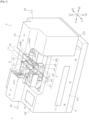
- the tube joining device 1 can be configured to include a housing 2, and a tube holding section 4 in which the tubes T1 and T2 are disposed in parallel and are held.
- the housing 2 is constituted by a case including a front surface portion 2A, a top surface portion 2B, a rear surface portion 2C, and a bottom surface portion 2D.
- the case has a substantially rectangular parallelepiped shape that is chamfered.
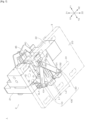
- the housing 2 includes a cover member 20 that is closed to cover fusing-joining sites C of the first tube T1 and the second tube T2, and a base 3 on which the cover member 20 is placed. As illustrated in Fig. 6 , in a state in which the cover member 20 is closed, the housing 2 accommodates respective constituent elements of the tube joining device 1 including the tube holding section 4 in a space surrounded by the cover member 20 and the base 3.
- a hard plastic can be used as a material of the housing 2.
- the cover member 20 is configured to be slidable along a direction in which the first tube T1 and the second tube T2 are disposed in parallel.
- the cover member 20 includes a first pressing member 21 and a second pressing member 22 which can relatively approach each other or can be separated from each other in a sliding direction, and maintain the first tube T1 and the second tube T2 in a pressed state in accordance with the approaching movement.
- the cover member 20 can be opened or closed by causing the second pressing member 22 to perform approaching movement or separating movement with respect to the first pressing member 21.
- a direction in which the cover member 20 slides is referred to as "sliding direction", and is indicated by arrows X1 andX2 in the drawings .
- directions which intersect the sliding directions X1 and X2 of the cover member 20 are indicated by arrows Y1 and Y2 in the drawings, and upper and lower directions of the tube joining device 1 are indicated by arrows Z1 and Z2 in the drawings.
- the directions Y1 and Y2, which intersect the sliding directions X1 and X2 of the cover member 20 are substantially orthogonal to the sliding directions X1 and X2, and correspond to a disposition direction (extension direction) of the tubes T1 and T2.
- a gap 23 is formed between the first pressing member 21 and the second pressing member 22 until the cover member 20 is closed.
- a user can visually confirm a setting position of the tubes T1 and T2 through the gap 23 until the cover member 20 is closed. According to this, the user can easily and appropriately perform setting of the tubes T1 and T2 which become a joining target, and it is possible to prevent occurrence of a joining failure caused by a setting error of the tubes in advance .
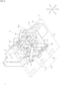
- the tube holding section 4 includes the first tube holding portion 41 that can hold the first tube T1, and the second tube holding portion 42 that is disposed adjacent to the first tube holding portion 41 and can hold the second tube T2 at a position that is parallel to the first tube T1.
- the first tube holding portion 41 and the second tube holding portion 42 are disposed between the first pressing member 21 and the second pressing member 22.
- the tube holding section 4 includes a first accommodation member 40A and a second accommodation member 40B which respectively accommodate the tubes T1 and T2, a joining site holding portion 43 that holds a fusing-joining site C of each of the first tube T1 and the second tube T2, a operation panel unit 44 that is disposed between a fusing-joining site C1 of the first tube T1 and a fusing-joining site C2 on the second tube T2 side, a support member 45 that supports the first tube holding portion 41 and the second tube holding portion 42 (refer to Fig. 9 ), and a clamp portion 46 that holds the tubes T1 and T2 so as not to cause positional deviation previous to execution of joining work.
- the first accommodation member 40A includes a first holding groove 401 that holds the first tube T1, and a second holding groove 402 that holds the second tube T2.
- the first holding groove 401 and the second holding groove 402 have a substantially U-shaped cross-section.
- the second accommodation member 40B is disposed with a predetermined gap with respect to the first accommodation member 40A in the directions Y1 and Y2 which intersect the sliding directions X1 and X2 of the cover member 20.
- the joining site holding portion 43 has a guide function of allowing work of setting the tubes T1 and T2 in the first accommodation member 40A and the second accommodation member 40B to be simply performed.
- the joining site holding portion 43 is disposed on a lower side of the first accommodation member 40A to be relatively movable with respect to the first accommodation member 40A in the disposition (extension) directions (Y1 and Y2 directions) of the tubes T1 and T2.
- the joining site holding portion 43 is configured to be relatively movable in synchronization with an opening and closing operation of the housing 2, with respect to the first accommodation member 40A in the disposition direction (Y1 and Y2 directions) of the tubes T1 and T2.
- the joining site holding portion 43 includes a cut-away portion 431 through which the partition portion 44 can be inserted.
- the partition portion 44 is inserted through the cut-away portion 431 of the joining site holding portion 43, and is located on an upper side of the joining site holding portion 43.
- the tubes T1 and T2 are disposed, and the tubes T1 and T2 are partitioned by the partition portion 44. Accordingly, it is possible to prevent a work error such as setting of the tubes T1 and T2 in a distorted state from occurring.
- the support member 45 is placed on the base 3, and supports the first accommodation member 40A from a lower side.
- a first jig 451 and a second jig 452 which extend in the sliding directions X1 and X2 of the cover member 20 are provided in the support member 45.
- the first jig 451 is inserted into a hole 21A provided in the first pressing member 21 to realize approaching movement of the support member 45 with respect to the first pressing member 21.
- the second jig 452 is inserted into a hole 21B provided in the first pressing member 21 to realize approaching movement of the support member 45 with respect to the first pressing member 21.
- a sliding groove 45A that extends in the directions Y1 and Y2 which intersect the sliding directions X1 and X2 of the cover member 20 is provided in the support member 45.
- the sliding groove 45A has a function of guiding a movement direction of a third support portion 133 of a first link mechanism 100 of the housing 2.
- the clamp portion 46 includes a first clamp portion 461 that is provided in the first pressing member 21, and a second clamp portion 462 that is provided in the second pressing member 22.
- the first clamp portion 461 and the second clamp portion 462 are disposed at positions which face each other.
- the housing 2 further includes a first link mechanism 100 that causes the first tube holding portion 41 and the second tube holding portion 42 to approach or to be separated from the first pressing member 21 in synchronization with approach and separation of the first pressing member 21 and the second pressing member 22.
- the first link mechanism 100 When causing the first tube holding portion 41 and the second tube holding portion 42 to approach or to be separated from the first pressing member 21, the first link mechanism 100 maintains the position of the first tube holding portion 41 and the second tube holding portion 42 at substantially the center PC between the first pressing member 21 and the second pressing member 22.
- the first link mechanism 100 includes a first link member 110 of which one end 111 is connected to the base 3 through a first support portion 131, and a second link member 120 of which one end 121 is fixed to the second pressing member 22 through a second support portion 132.
- the first support portion 131 supports the first link member 110 to rotate around a central axis CL1 (rotation axis).
- a sliding groove 31 that extends in the sliding directions X1 and X2 along which the first pressing member 21 and the second pressing member 22 approach or are separated from each other is provided in the base 3.
- the sliding groove 31 has a function of guiding a movement direction of the second support portion 132 of the first link mechanism 100 of the housing 2.
- the second support portion 132 slides along the sliding groove 31 provided in the base 3 to move along the sliding directions X1 and X2.
- the other end 112 of the first link member 110 and the other end 122 of the second link member 120 are connected by the third support portion 133.
- the third support portion 133 is configured to move along the directions Y1 and Y2 which intersect the sliding directions X1 and X2 of the cover member 20 by sliding along the sliding groove 45A provided in the support member 45 of the tube holding section 4.
- the first link member 110 and the second link member 120 are disposed on the same plane to be symmetry with respect to the center PC.
- the second support portion 132 slides along the sliding groove 31 of the base 3 and moves in the X1 direction as illustrated in Fig. 7 and Fig. 8 .
- the third support portion 133 slides along the sliding groove 45A of the support member 45 and moves in the Y1 direction while pressing and moving the tube holding section 4 in the X1 direction through the sliding groove 45A of the support member 45.
- the first link member 110 and the second link member 120 are disposed to be symmetry with respect to the center PC.
- a distance L1 between the first support portion 131 and the third support portion 133 along the sliding directions X1 and X2 of the cover member 20, and a distance L2 between the second support portion 132 and the third support portion 133 along the sliding directions X1 and X2 of the cover member 20 become the same as each other (refer to Fig. 7 ). Accordingly, when the first pressing member 21 and the second pressing member 22 move, the first link mechanism 100 can maintain the position of the first tube holding portion 41 and the second tube holding portion 42 at substantially the center PC between the first pressing member 21 and the second pressing member 22.
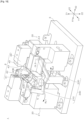
- the second clamp portion 462 approaches the first clamp portion 461 as illustrated in Fig. 2 .
- the clamp portion 46 holds the tubes T1 and T2 and compresses the tubes T1 and T2 in a direction of approaching each other.
- the first link mechanism 100 maintains the position of the first tube holding portion 41 and the second tube holding portion 42 at substantially the center PC between the first pressing member 21 and the second pressing member 22, and thus it is possible to uniformly compress the first tube T1 and the second tube T2 from the sliding directions X1 and X2 of the cover member 20.
- the housing 2 further includes a second link mechanism 200 that retracts the joining site holding portion 43 from a space between the first pressing member 21 and the second pressing member 22 in synchronization with approach and separation of the first pressing member 21 and the second pressing member 22.
- the second link mechanism 200 includes a first link member 210 of which one end 211 is connected to the first pressing member 21 to rotate around the central axis CL2, and a second link member 220 of which one end 221 is connected to the second pressing member 22 to rotate around a central axis CL3.
- the other end 212 of the first link member 210 and the other end 222 of the second link member 220 are connected to a protrusion 43A that is provided at substantially the center PC of the joining site holding portion 43 to rotate around a central axis CL4.
- the joining site holding portion 43 is disposed at the fusing-joining sites C of the tubes T1 and T2. According to this, when setting the tubes T1 and T2 in the tube holding section 4, it is possible to support the tubes T1 and T2 by the joining site holding portion 43, and thus it is possible to prevent the tubes T1 and T2 from being bent or distorted at the fusing-joining sites C.
- the second link mechanism 200 retracts the joining site holding portion 43 from the fusing-joining sites C (refer to Fig. 1 ) between the first pressing member 21 and the second pressing member 22. According to this, in the fusing work and joining work of the tubes T1 and T2, the joining site holding portion 43 does not interfere movement of the tubes T1 and T2 or the wafer WF, and thus it is possible to smoothly perform the fusing work and the joining work.
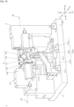
- the housing 2 includes a third link mechanism 300 that retracts the partition portion 44 from a space between the first pressing member 21 and second pressing member 22 in synchronization with the approaching movement of the first pressing member 21 and the second pressing member 22.
- the third link mechanism 300 includes a first link member 310 that is connected to the second pressing member 22, a second link member 320 that is connected to the partition portion 44, and a third link member 330 that causes an operation of the first link member 310 to synchronize with an operation of the second link member 320.
- the first link member 310 slides in combination with the second pressing member 22 to approach or to be separated from the first pressing member 21.
- the first link member 310 includes a first sliding groove 311 along which a protrusion 331 provided in the third link member 330 can slide.
- the second link member 320 includes a second sliding groove 321 along which a support portion 332 fixed to the third link member 330 can slide.
- the protrusion 331 of the third link member 330 slides along the first sliding groove 311 and moves in a downward direction Z2 as illustrated in Fig. 13 .
- the support portion 332 fixed to the third link member 330 also slides along the second sliding groove 321 while moving in the downward direction Z2.
- the second link member 320 is drawn by the support portion 332 in the downward direction Z2, and the partition portion 44 moves in the downward direction Z2 and is retracted from a space between the tubes T1 and T2.
- the partition portion 44 is not disposed between the tubes T1 and T2, and thus it is possible to smoothly perform the fusing work and the joining work.
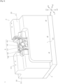
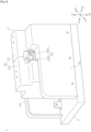
- a speaker SP that emits sound, and a fan FN that discharges a gas inside the housing 2 are disposed on the bottom surface portion 2D of the housing 2 (refer to Fig. 16 ) .
- the fan FN also has a function as a cooling fan that cools down the wafer WF after terminating a joining operation.
- the housing 2 includes an operation panel unit 7 that includes switches, and a display unit 8.
- the operation panel unit 7 is disposed on the front surface portion 2A (refer to Fig. 1 ) of the housing 2 which is located in the direction Y1 that intersects the sliding directions X1 and X2 of the cover member 20.
- the display unit 8 is disposed on the top surface portion 2B (refer to Fig. 1 ) of the housing 2 which is located in the upward direction Z1.
- the operation panel unit 7 includes a [power] switch button 7B, [power] lamp 7C, a [in-charging] lamp 7D, a [joining] button 7E, a [joining] lamp 7F, and a [wafer ejecting] lamp 7G.
- the [power] lamp 7C, the [in-charging] lamp 7D, the [joining (welding)] lamp 7F, and the [wafer ejecting] lamp 7G are display lamps indicating various states in the operation panel unit 7.
- the respective lamps can be constituted by a green light-emitting diode (LED) lamp.
- the [power] switch button 7B is a button that is pressed to supply power to the tube joining device 1.
- the [power] lamp 7C is lightened when pressing the [power] switch button 7B.
- the [joining] button 7E is a button that is pressed when a user initiates fusing-joining work of fusing ends of the two tubes T1 and T2 and replacing and pressure-joining the ends of the tubes T1 and T2.
- the [joining] lamp 7F is lightened when the [joining] button 7E is pressed.
- the [joining] lamp 7F may be configured to be flickered to give an alarm of a failure state to a user at the time of failure of the tube joining device 1.
- the [in-charging] lamp 7D is lightened in a case where charging with respect to a battery BA from a commercial AC power side is performed.
- the [wafer ejecting] lamp 7G is lightened or flickered when joining between the two tubes T1 and T2 is terminated and it enters a state in which a user can eject from the housing 2 the wafer WF that has been used and discharge the wafer WF.
- the display unit 8 includes a [cover close] lamp 8B, a [wafer cassette exchange] lamp 8C, a [defective wafer] lamp 8D, a [charging required] lamp 8E, an [inappropriate room temperature] lamp 8F, and a [device failure] lamp 8G.
- the [device failure] lamp 8G is an alarm lamp that gives a notification of failure of the tube joining device 1.
- the [device failure] lamp 8G can be constituted by a red LED lamp.
- the other lamps are constituted as an alarm display lamp, and can be constituted by, for example, a yellow LED lamp.
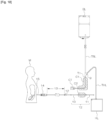
- Fig. 18 illustrates the two tubes T1 and T2 which are joined by the tube joining device 1.
- the tubes T1 and T2 for example, a vinyl chloride tube having flexibility can be selected.
- the material of the tubes T1 and T2 is not limited as long as the tubes T1 and T2 can be joined to each other through fusing and pressing.
- materials of the tubes T1 and T2 may be different from each other.
- a predetermined connector CT is attached to a tip end side of one end of the first tube T1.
- the other end side of the first tube T1 is connected to a dialysis fluid tube TBL of a dialysis fluid bag BL through a diverging tube 9.
- the first tube T1 is connected to a fluid discharge tube THL of a fluid discharge bag HL through the diverging tube 9.
- the tube T2 includes an extension tube 10 and a protection tube 11.
- the extension tube 10 is connected to a peritoneal catheter 15 through a connection tube 12, a silicone tube 13, and a catheter joint 14.
- One end side of the peritoneal catheter 15 is inserted into an abdominal cavity of a patient M.
- the tube joining device 1 fuses the joining sites C1 and C2 by using a heated wafer WF (refer to Figs. 19(A) and 19(B) ). In addition, after the fusing, a fused end of the first tube T1 and a fused end of the second tube T2 are replaced, and the ends are pressed and joined (refer to Figs. 19(C) and 19(D) ).
- the tubes T1 and T2 are held by the first tube holding portion 41 and the second tube holding portion 42 which are provided in the housing 2 so as not to cause positional deviation.
- the clamp portion 46 holds the tubes T1 and T2
- the tubes T1 and T2 are set in a state of pressing each other (refer to Fig. 3 ) .
- the tubes T1 and T2 are fused by using the heated wafer WF.
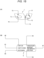
- Fig. 16 illustrates an electric block of the tube joining device 1.
- the tube joining device 1 includes a control unit 500 that collectively controls operations of respective units of the device.
- the control unit 500 includes a CPU such as a microcomputer, a ROM that stores a control program of the entirety of the device which is executed by the CPU or various pieces of data, and a RAM that temporarily stores measurement data or various pieces of data as a work area.
- the control unit 500 is supplied with power from the battery BA on the DC input substrate 81 side.
- the DC input substrate 81 includes a jack 84 and a switching switch 85.
- the jack 84 receives a predetermined DC power that is AC/DC converted from a commercial AC power supply.
- the charger 86 and the jack 84 are also illustrated in Fig. 1 .
- the switching switch 85 connects the jack 84 and the battery BA.
- DC power from the charger 86 can be used in charging of the battery BA.
- the DC power charged in the battery BA is supplied to the control unit 500.
- a temperature sensor 87 such as a thermistor is electrically connected to the control unit 500.
- the temperature sensor 87 detects an environment temperature (outside air temperature) around the housing 2, and supplies outside air temperature information TF to the control unit 500.
- the control unit 500 refers to the outside air temperature information TF, and for example, in a case where the outside air temperature is lower than a temperature that is determined in advance, the control unit 500 executes processing of lengthening a heating time of the two tubes T1 and T2.
- the control unit 500 performs operation control so that a patient is notified of the environment temperature with the speaker SP.
- the [power switch] button 7B, the [joining] button 7E, and the lamps 7C, 7D, 7F, and 7G of the operation panel unit 7 which are illustrated in Fig. 15 (A) are electrically connected to the control unit 500.
- the speaker SP is electrically connected to the control unit 500 through a voice synthesis unit 88.
- the speaker SP emits, for example, a voice guidance that is determined in advance in accordance with a command of the control unit 500.
- a voice adjusting volume 26 and a voice/message switching switch 27 are electrically connected to the control unit 500.
- the voice/message switching switch 27 is "turned on”, a voice guidance can be emitted from the speaker SP, and in a case where the voice/message switching switch 27 is "turned off”, it is possible to sound a buzzer (not illustrated).
- the [cover close] button 8B, the [wafer cassette exchange] lamp 8C, the [defective wafer] lamp 8D, the [charging required] lamp 8E, the [inappropriate room temperature] lamp 8F, and the [device failure] lamp 8G of the display unit 8 are configured to be lightened or flickered in accordance with a command of the control unit 500.
- a hall sensor 90 of the clamp portion 46 is electrically connected to the control unit 500, and is configured to transmit a detection result to the control unit 500.
- a tube detection pin 75 is pressed to a downward side of the device against a force of the spring 92 due to the first tube T1 and the second tube T2. Due to the pressing, the tube detection pin 75 descends, and thus a magnetic force of a magnet 91 is detected by the hall sensor 90.
- the hall sensor 90 transmits a signal for giving a notification that "the two tubes T1 and T2 are correctly inserted" to the control unit 500.
- the hall sensor 90 cannot detect the magnetic force of the magnet 91. At this time, the hall sensor 90 transmits a signal for giving a notification that "the two tubes T1 and T2 are not correctly inserted" to the control unit 500. Furthermore, a position of installing the tube detection pin 75 is not limited to the position illustrated in Fig. 18 as long as it is possible to detect whether or not the tubes T1 and T2 are set in the clamp portion 46 at the position.
- the clamp portion 46 includes a microswitch 93.
- the microswitch 93 is a sensor that detects a closed state of the housing 2. When the second pressing member 22 is caused to slide and approach the first pressing member 21 as illustrated in Fig. 6 , the microswitch 93 detects that the clamp plate 30 closes the clamp portion 46 as illustrated in Fig. 1 .
- the microswitch 93 for example, it is possible to use a known sensor such as a mechanic type sensor that detects closing by contact with an arbitrary position of the housing 2 when closing the clamp portion 46, and an electric type sensor that detects closing on the basis of a position of the clamp portion 46.
- the wafer cassette storage unit 82 includes a wafer presence/absence sensor 501 and a wafer residual amount detection sensor 502.
- the wafer presence/absence sensor 501 is a sensor that detects whether or not the wafer WF remains in the wafer cassette WC.
- the wafer residual amount detection sensor 502 is a sensor that detects how many sheets of wafers WF remain inthewafercassetteWC, thatis, the number of sheets of remaining wafer WF.
- a known photosensor or the like can be used as the wafer presence/absence sensor 501 and the wafer residual amount detection sensor 502, for example.
- the wafer delivery unit 83 is a unit that linearly moves the wafer WF in the wafer cassette WC to a predetermined stand-by position (refer to Fig. 18 ) .
- the wafer delivery unit 83 includes a motor 503, a motor drive 504, a forward edge sensor 505, an intermediate sensor 506, and a backward edge sensor 507.
- the motor drive 504 drives the motor 503, and linearly moves the wafer in the wafer cassette WC to the stand-by position sheet by sheet.
- the control unit 500 is electrically connected to a wafer heating heater 510, a motor drive 511, a cam motor sensor 512, a clamp motor sensor 513, a microswitch 514, a wafer current detection unit 515, a wafer voltage detection unit 516, and the fan FN.
- the motor drive 511 receives a command from the control unit 500, the motor drive 511 drives the cam motor 517 or the clamp motor 56 to fuse and join the tubes T1 and T2.
- the cam motor 517 performs an operation of vertically moving the wafer WF, and an operation of pressing the two tubes T1 and T2 against each other.
- the operation of vertically moving the wafer WF by the cam motor 517 is an operation of ascending the wafer WF from the stand-by position to a fusing position PSm on an upward side of the stand-by position, and descending the wafer WF from the fusing position PSm to the stand-by position in a contrast manner (refer to Fig. 19 ) .
- the cam motor 517 performs an operation of pressing the tubes T1 and T2 against each other after fusing the two tubes T1 and T2.
- the pressing operation is an operation of causing the wafer WF to enter a stand-by state by descending the wafer WF from the fusing position PSm to the stand-by position, and of performing joining by pressing an end of the first tube T1 on one side to an end of the second tube T2 on the other side, and pressing an end of the second tube T2 on the one side to an end of the first tube T1 on the other side and performing joining.
- the clamp motor 56 performs rotation of the movable clamp unit 72 by 180° and returning rotation after the rotation by 180° (refer to Fig. 19 ) .
- An operation of the movable clamp unit 72 will be described later.
- the cam motor sensor 512 is constituted by, for example, a photosensor that detects a cam position and the original point.
- the clamp motor sensor 513 is constituted by, for example, a photosensor that detects the original point during rotation of the movable clamp unit 72.
- the wafer heating heater 510 is provided to heat a wafer in accordance with a command from the control unit 500.
- the wafer current detection unit 515 detects a wafer current value that is supplied to the wafer.
- the wafer voltage detection unit 516 detects a wafer voltage value that is supplied to the wafer.
- Fig. 17(A) is a perspective view illustrating a lower surface side of the wafer cassette WC
- Fig. 17(B) is a perspective view illustrating an upper surface side of the wafer cassette WC.
- the wafer cassette WC is constituted by a container for accommodating a plurality of sheets of the wafers WF.
- the wafer cassette WC is preferably formed from a transparent plastic to visually confirm an inner side of the wafer WF.
- the wafer cassette WC includes a top surface portion 520, a bottom surface portion 521, a front surface portion 522, lateral surface portions 523 and 524, and a bottom surface portion 525.
- the wafer WF is disposed sheet by sheet on an inner side of the front surface portion 522.
- a pushing member 526 when pressing a pushing member 526 with respect to the wafer WF in a Y3 direction, one sheet of wafer WF is pushed out from the inside of the wafer cassette WC to a predetermined stand-by position along the Y3 direction.
- the spring accommodation member 529 includes a positional deviation preventing portion 530 in order for each of the springs 528 not to deviate.
- the two springs 528 press a plurality of sheets of the wafers WF against an inner surface of the front surface portion 522 through the spring accommodation member 529.
- the pushing member 526 is pressed against the wafer WF located on the front surface portion 522 side in the Y3 direction, only one sheet of the wafer WF located on the outermost side is output from the inside of the wafer cassette WC along the Y3 direction.
- the wafer WF that can be used as a cutting member is constituted by a copper metal plate (a thickness: approximately 0.3 mm, a width: approximately 34 mm, and a height: approximately 13 mm) that can be heated by the wafer heating heater 510 (refer to Fig. 16 and Fig. 18 ) and is formed in a substantially rectangular shape. Furthermore, the wafer WF has two contact points 531 which are connected to the wafer heating heater 510 when being heated.
- a user sets the tubes T1 and T2 in the tube holding section 4 in using the tube joining device 1.
- the user presses the [joining] button 7E illustrated in Fig. 1 to initiate the fusing-joining work by the tube joining device 1.
- the tube joining device 1 performs the fusing-joining work in a state in which a part of the tubes T1 and T2 is covered with the housing 2.
- the second clamp portion 462 that is disposed in the second pressing member 22 approaches the first clamp portion 461 that is disposed in the first pressing member 21 to be integrated with each other, thereby forming the movable clamp unit 72 that replaces ends of the tubes T1 and T2 which are fused by the wafer WF.
- the second clamp portion 462 that is provided in the clamp portion 46 approaches the first clamp portion 461 to be integrated with each other, thereby forming a fixed clamp unit 71 that fixedly holds the tubes T1 and T2 which are fused by the wafer WF.
- a predetermined gear 55 can be formed at the periphery of the tube holding portion 6.
- the gear 55 can be configured to engage with a gear 56G of the clamp motor 56 that drives an operation of replacing positions of ends of the tubes T1 and T2 after fusing the tubes T1 and T2.
- the clamp motor 56 operates by a command of the control unit 500 (refer to Fig. 16 ) and rotates the gear 56G
- the first clamp portion 461 and the second clamp portion 462 positively rotate by 180° in an integrated state.
- the fused end of the first tube T1 on the other side and the fused end of the second tube T2 on the other side rotate and positions thereof are replaced. According to this, positions of the fused end of the first tube T1 on the other side and the fused end of the second tube T2 on the other side are laterally reversed by 180°.
- the end of the first tube T1 on one side and the end of the second tube T2 on the other side can be joined to each other, and the end of the first tube T1 on the other side and the end of the second tube T2 on the one side can be joined to each other.
- the fixed clamp unit 71 that is constituted by the clamp portion 46 holds the end of the first tube T1 on the one side and the end of the second tube T2 on the one side in a position-fixed manner, and prevents the ends from erroneously rotating.
- a user sets the housing 2 in an opened state as illustrated in Fig. 1 .
- the user performs an operation of closing the housing 2 as illustrated in Fig. 2 to cause the second pressing member 22 to approach the first pressing member 21 in the approaching direction X1.
- the joining site holding portion 43 moves in the Y1 direction to be retracted from a space between the first pressing member 21 and the second pressing member 22.
- the partition portion 44 is retracted from a space between the first pressing member 21 and the second pressing member 22.
- the user further causes the second pressing member 22 to approach the first pressing member 21 in the approaching direction X1.
- a tube pressing operation by the clamp portion 46 is initiated.
- the first clamp portion 461 and the second clamp portion 462 are integrated with each other.
- the fusing-joining sites C of the tubes T1 and T2 can be visually confirmed through the gap 23 formed between the first pressing member 21 and the second pressing member 22. According to this, it is possible to visually confirm that the tubes T1 and T2 are correctly set in the tube holding section 4.
- the outer periphery of the fusing-joining sites C of the tubes T1 and T2 is covered with the cover member 20, and thus it is possible to perform the fusing and the subsequent joining work in an aseptic condition.
- fusing of the tubes T1 and T2 is performed by the heated wafer WF.
- the wafer WF is guided to the fusing-joining sites C of the tubes T1 and T2 from a stand-by position, and passes between the first accommodation member 40A and the clamp portion 46 and fuses the tubes T1 and T2.
- the wafer WF is returned to the stand-by position after fusing the tubes T1 and T2.
- the movable clamp unit 72 is rotated to rotate the end of the first tube T1 on the other side and the end of the second tube T2 on the other side, thereby replacing positions of the both ends. Then, as illustrated in Fig. 19 (D) , the replaced ends of the tubes T1 and T2 are pressed against each other, and are pressure-joined.
- the housing 2 is opened as illustrated in Fig. 1 to expose the inside of the housing 2 to the outside. According to this, the user can detach the tubes T1 and T2 from the device.
- the tubes T1 and T2 enter a joined state as illustrated in fig. 20(A) .
- the user detaches the tubes T1 and T2 from the clamp portion 46, and performs work of separating the tubes T1 and T2.
- the separation work is performed, as illustrated in Fig.
- the housing 2 After using the tube joining device 1, the housing 2 is set to a closed state.
- the movable clamp unit 72 automatically rotates to perform a reset operation of returning the position of the tube holding section 4, the clamp portion 46, and the tube holding portion 6 to the original position.
- the tube holding section 4 is disposed at an initiation position (initial position) of the fusing-joining work as illustrated in Fig. 1 . Accordingly, it is possible to perform the fusing-joining work by operating the tube joining device 1 in the same procedure as the above-described procedure.
- the tube joining device 1 is a tube joining device that fuses an end of the first tube T1 and an end of the second tube T2 by the wafer WF (plate-shaped cutting member) that is heated, and replaces a fused end of the first tube T1 and a fused end of the second tube T2 and joins the fused ends in an aseptic condition and sterile condition.
- the wafer WF plate-shaped cutting member
- the tube joining device 1 includes the first tube holding portion 41 that can hold the first tube T1, the second tube holding portion 42 that is disposed adjacent to the first tube holding portion 41 and can hold the second tube T2 at a position that is parallel to the first tube T1, and the housing 2 that is provided with the cover member 20 that is closed to cover the fusing-joining sites C of the first tube T1 and the second tube T2.
- the cover member 20 is slidable in a direction in which the first tube T1 and the second tube T2 are disposed in parallel.
- a user can dispose the tubes T1 and T2 in parallel by setting the tubes T1 and T2 individually in the first and second tube holding portions 41 and 42.
- the user can cause the tubes T1 and T2 to be pressed against each other to come into close contact with each other by operating the cover member 20 that is provided in the tube joining device 1, and thus it is possible to perform setting work of the tubes in a simple manner.
- it is not necessary for the user to manually perform work of superimposing the tubes T1 and T2, and thus it is possible to prevent a work error such as setting of the tubes in a distorted state from occurring.
- the cover member 20 is slidable along a direction in which the first tube T1 and the second tube T2 are disposed in parallel, it is possible to visually confirm a setting position of the tubes T1 and T2 up to a time immediately before the cover member 20 is closed. Accordingly, it is possible to prevent a joining failure caused by a tube setting error from occurring in advance.
- the cover member 20 includes the first pressing member 21 and the second pressing member 22 which are capable of relatively approaching each other or being relatively separated from each other along the sliding directions X1 and X2, and maintain the first tube T1 and the second tube T2 in a pressed state in accordance with the approaching movement.
- the first tube holding portion 41 and the second tube holding portion 42 are disposed between the first pressing member 21 and the second pressing member 22.
- the housing 2 includes the first link mechanism 100 that causes the first tube holding portion 41 and the second tube holding portion 42 to approach the first pressing member 21 or to be separated therefrom in synchronization with the approach or separation of the first pressing member 21 and the second pressing member 22.
- the first link mechanism 100 maintains the position of the first tube holding portion 41 and the second tube holding portion 42 at substantially the center PC between the first pressing member 21 and the second pressing member 22, and thus it is possible to uniformly compress the first tube T1 and the second tube T2 from the sliding directions X1 and X2 of the cover member 20.
- first tube holding portion 41 and the second tube holding portion 42 include the joining site holding portion 43 that holds the fusing-joining site C of each of the first tube T1 and the second tube T2.
- the housing 2 includes the second link mechanism 200 that retracts the joining site holding portion 43 from a space between the first pressing member 21 and the second pressing member 22 in synchronization with the approach or separation of the first pressing member 21 and the second pressing member 22. According to this, it is possible to reliably maintain a state in which fusing-joining sites C of the tubes T1 and T2 are disposed in parallel until the first tube T1 and the second tube T2 are pressed to come into close contact with each other.
- first tube holding portion 41 and the second tube holding portion 42 include the partition portion 44 that is disposed between the fusing-joining site C1 of the first tube T1 and the fusing-joining site C2 of the second tube T2 side.
- the housing 2 includes the third link mechanism 300 that retracts the partition portion 44 from a space between the first pressing member 21 and the second pressing member 22 in synchronization with the approach or separation of the first pressing member 21 and the second pressing member 22. According to this, the tubes T1 and the T2 are partitioned by the partition portion 44, and thus it is possible to more reliably prevent occurrence of a work error such as setting in a state in which the fusing-joining sites C of the tubes T1 and T2 are distorted.
- the housing 2 includes the operation panel unit 7 including switches, and the operation panel unit 7 is disposed on the front surface portion 2A of the housing 2 which is located in the directions Y1 and Y2 which intersect the sliding directions X1 and X2 of the cover member 20. According to this, when a user sets the tubes T1 and T2, the operation panel unit 7 is located in front of the user, and thus an operation becomes easy. As a result, it is possible to provide the tube joining device 1 of which convenience is further improved.
- the configuration of the housing or the respective portions of the tube joining device can be modified in correspondence with a use and a purpose of the device, design circumstances and the like, and thus there is no limitation to the configuration illustrated in the drawing.
- the pressing portions may be configured to cause at least one tube to approach the other tube to be pressed against each other, and are not limited to the configuration in which both the tubes are caused to approach each other as described in this embodiment.
- the tubes which become a joining target may be tubes of which positions of ends after being fused are replaced with each other and are subjected to pressure-joining, and there is no limitation to the tubes used in the peritoneal dialysis.
- first tube holding portion holds the first tube
- second tube holding portion holds the second tube
- the first tube holding portion can hold the second tube
- the second tube holding portion can hold the first tube
Landscapes
- Engineering & Computer Science (AREA)
- Mechanical Engineering (AREA)
- Health & Medical Sciences (AREA)
- Physics & Mathematics (AREA)
- Thermal Sciences (AREA)
- Toxicology (AREA)
- Heart & Thoracic Surgery (AREA)
- Anesthesiology (AREA)
- Pulmonology (AREA)
- Biomedical Technology (AREA)
- Hematology (AREA)
- Life Sciences & Earth Sciences (AREA)
- Animal Behavior & Ethology (AREA)
- General Health & Medical Sciences (AREA)
- Public Health (AREA)
- Veterinary Medicine (AREA)
- External Artificial Organs (AREA)
- Infusion, Injection, And Reservoir Apparatuses (AREA)
- Lining Or Joining Of Plastics Or The Like (AREA)
Claims (6)
- Schlauchverbindungsvorrichtung (1), die ein Ende eines ersten Schlauchs (T1) und ein Ende eines zweiten Schlauchs (T2) durch ein plattenförmiges Schneidelement (WF) verschmilzt, das erwärmt wird und ein verschmolzenes Ende des ersten Schlauchs (T1) und ein verschmolzenes Ende des zweiten Schlauchs (T2) ersetzt und die verschmolzenen Enden unter aseptischen Bedingungen zusammenfügt, wobei die Schlauchverbindungsvorrichtung (1) hat:einen ersten Schlauchhalteabschnitt (41), der einen beliebigen Schlauch zwischen dem ersten Schlauch (T1) und dem zweiten Schlauch (T2) halten kann;einen zweiten Schlauchhalteabschnitt (42), der angrenzend an den ersten Schlauchhalteabschnitt (41) vorgesehen ist und den anderen Schlauch zwischen dem ersten Schlauch (T1) und dem zweiten Schlauch (T2) in einer Position halten kann, die parallel zu dem einen Schlauch liegt; undein Gehäuse (2), das mit einem Abdeckelement (20) bereitgestellt ist, das geschlossen ist, um die Schmelz- und Zusammenfügungsstellen des ersten Rohrs (T1) und des zweiten Rohrs (T2) abzudecken,dadurch gekennzeichnet, dassdas Abdeckelement (20) entlang einer Richtung verschiebbar ist, die senkrecht zu einer Anordnungsrichtung (Y1, Y2) des ersten und zweiten Schlauchs (T1, T2) ist, wobei der erste Schlauch (T1) und der zweite Schlauch (T2) parallel zueinander vorgesehen sind.
- Schlauchverbindungsvorrichtung (1) gemäß Anspruch 1,wobei das Abdeckelement (20) ein erstes Drückelement (21) und ein zweites Drückelement (22) hat, die in der Lage sind, sich entlang einer Gleitrichtung relativ anzunähern oder relativ voneinander getrennt zu werden, und die den ersten Schlauch (T1) und den zweiten Schlauch (T2) gemäß der Annäherungsbewegung in einem gedrückten Zustand halten,der erste Schlauchhalteabschnitt (41) und der zweite Schlauchhalteabschnitt (42) zwischen dem ersten Drückelement (21) und dem zweiten Drückelement (22) vorgesehen sind unddas Gehäuse (2) einen Gelenkmechanismus (100) als einen ersten Gelenkmechanismus (100) hat, der bewirkt, dass sich der erste Schlauchhalteabschnitt (41) und der zweite Schlauchhalteabschnitt (42) dem ersten Drückelement (21) annähern oder davon getrennt werden, und zwar synchron mit der Annäherung oder Trennung des ersten Drückelements (21) und des zweiten Drückelements (22).
- Schlauchverbindungsvorrichtung (1) gemäß Anspruch 2, wobei
der erste Gelenkmechanismus (100) die Position des ersten Abschnitts (41) zum Halten des Schlauchs und des zweiten Abschnitts (42) zum Halten des Schlauchs im Wesentlichen im Mittelpunkt zwischen dem ersten Drückelement (21) und dem zweiten Drückelement (22) hält, wenn sich das erste Drückelement (21) und das zweite Drückelement (22) relativ zueinander bewegen. - Schlauchverbindungsvorrichtung (1) gemäß Anspruch 2 oder 3, wobeider erste Schlauchhalteabschnitt (41) und der zweite Schlauchhalteabschnitt (42) einen Verbindungsstellenhalteabschnitt (43) haben, der eine Schmelzverbindungsstelle von jedem des ersten Schlauchs (T1) und des zweiten Schlauchs (T2) hält, unddas Gehäuse (2) einen Gelenkmechanismus (200) hat, der den Verbindungsstellenhalteabschnitt (43) aus einem Raum zwischen dem ersten Drückelement (21) und dem zweiten Drückelement (22) synchron mit dem Annähern oder dem Trennen des ersten Drückelements (21) und des zweiten Drückelements (22) zurückzieht.
- Schlauchverbindungsvorrichtung (1) gemäß einem der Ansprüche 2 bis 4, wobeider erste Schlauchhalteabschnitt und der zweite Schlauchhalteabschnitt (42) einen Trennabschnitt (44) haben, der zwischen der Verschmelzungsverbindungsstelle des ersten Schlauchs (T1) und der Verschmelzungsverbindungsstelle der zweiten Schlauchseite vorgesehen ist, unddas Gehäuse (2) einen Gelenkmechanismus (300) hat, der den Trennabschnitt (44) aus einem Raum zwischen dem ersten Drückelement (21) und dem zweiten Drückelement (22) synchron mit dem Annähern oder dem Trennen des ersten Drückelements (21) und des zweiten Drückelements (22) zurückzieht.
- Schlauchverbindungsvorrichtung (1) gemäß einem der Ansprüche 1 bis 5, wobeidas Gehäuse (2) eine Bedienungskonsole (7) mit Schaltern hat unddie Bedienungskonsole (7) an einem Abschnitt der Vorderseite des Gehäuses (2) vorgesehen ist, der in einer Richtung liegt, die die Gleitrichtung des Abdeckelements (20) schneidet.
Applications Claiming Priority (2)
| Application Number | Priority Date | Filing Date | Title |
|---|---|---|---|
| JP2017059208 | 2017-03-24 | ||
| PCT/JP2018/011685 WO2018174245A1 (ja) | 2017-03-24 | 2018-03-23 | チューブ接合装置 |
Publications (3)
| Publication Number | Publication Date |
|---|---|
| EP3603735A1 EP3603735A1 (de) | 2020-02-05 |
| EP3603735A4 EP3603735A4 (de) | 2021-01-06 |
| EP3603735B1 true EP3603735B1 (de) | 2025-01-15 |
Family
ID=63586066
Family Applications (1)
| Application Number | Title | Priority Date | Filing Date |
|---|---|---|---|
| EP18772245.9A Active EP3603735B1 (de) | 2017-03-24 | 2018-03-23 | Rohrverbindungsvorrichtung |
Country Status (5)
| Country | Link |
|---|---|
| US (1) | US10864685B2 (de) |
| EP (1) | EP3603735B1 (de) |
| JP (1) | JP6928643B2 (de) |
| CN (1) | CN110475583B (de) |
| WO (1) | WO2018174245A1 (de) |
Families Citing this family (8)
| Publication number | Priority date | Publication date | Assignee | Title |
|---|---|---|---|---|
| CN114789561B (zh) | 2021-01-25 | 2024-11-15 | 汾沃有限公司 | 管的无菌连接 |
| DE102022200748A1 (de) | 2022-01-24 | 2023-07-27 | Raumedic Ag | Verfahren zur Konnektierung zweier Silikon-Schlauchabschnitte sowie pharmazeutisches Medientransferverfahren mit einem derartigen Konnektierungsverfahren und Vorrichtung zum Durchführen des Verfahrens |
| US20240325714A1 (en) * | 2023-03-30 | 2024-10-03 | Terumo Bct, Inc. | Automatic weld/reset motion of clamps after clamp closing/opening and tube removal |
| DE102023205432A1 (de) | 2023-06-12 | 2024-12-12 | Raumedic Ag | Verfahren zur Konnektierung zweier Schlauchabschnitte, Schlauch-Baugruppe, konnektiert mit dem Verfahren, Verfahren zum Verschließen eines Schlauchabschnitts sowie Schlauch-Baugruppe, hergestellt mit dem Verschluss-Verfahren |
| DE102023205431A1 (de) | 2023-06-12 | 2024-12-12 | Raumedic Ag | Vorrichtung zur Konnektierung zweier Silikon-Schlauchabschnitte im Rahmen eines pharmazeutischen Medientransferverfahrens |
| DE102023205430A1 (de) | 2023-06-12 | 2024-12-12 | Raumedic Ag | Verfahren zur Konnektierung zweier Schlauchabschnitte, Schlauch-Baugruppe, konnektiert mit dem Verfahren, Verfahren zum Verschließen eines Schlauchabschnitts sowie Schlauch-Baugruppe, hergestellt mit dem Verschluss-Verfahren |
| DE102023206594A1 (de) | 2023-07-11 | 2025-01-16 | Raumedic Ag | Vorrichtung zur Konnektierung zweier Silikon-Schlauchabschnitte im Rahmen eines pharmazeutischen Medientransferverfahrens |
| EP4706741A1 (de) * | 2024-09-06 | 2026-03-11 | Geuder AG | Chirurgisches system für ophthalmologische eingriffe |
Citations (1)
| Publication number | Priority date | Publication date | Assignee | Title |
|---|---|---|---|---|
| JP2013146354A (ja) * | 2012-01-18 | 2013-08-01 | Terumo Corp | 無菌接合装置 |
Family Cites Families (8)
| Publication number | Priority date | Publication date | Assignee | Title |
|---|---|---|---|---|
| JP3863271B2 (ja) * | 1997-12-22 | 2006-12-27 | テルモ株式会社 | チューブ接続装置 |
| KR100964057B1 (ko) * | 2002-08-30 | 2010-06-16 | 테루모 가부시키가이샤 | 튜브 접합 장치 및 튜브 접합 방법 |
| JP4585528B2 (ja) * | 2007-01-24 | 2010-11-24 | テルモ株式会社 | チューブ接続装置 |
| CN101108539A (zh) * | 2007-09-03 | 2008-01-23 | 顾振财 | 全自动尼龙拉链双上止机的塑胶扁丝切断、折弯成型机构 |
| JP2010082222A (ja) * | 2008-09-30 | 2010-04-15 | Terumo Corp | チュ−ブ接合装置 |
| EP2420286A1 (de) * | 2010-08-18 | 2012-02-22 | Fresenius Kabi Deutschland GmbH | Verfahren und Vorrichtung zum sterilen Verbinden von Schläuchen |
| JP6349184B2 (ja) * | 2014-07-22 | 2018-06-27 | テルモ株式会社 | チューブ接合装置 |
| US20170083892A1 (en) | 2015-09-17 | 2017-03-23 | Toshiba Tec Kabushiki Kaisha | Checkout apparatus |
-
2018
- 2018-03-23 WO PCT/JP2018/011685 patent/WO2018174245A1/ja not_active Ceased
- 2018-03-23 JP JP2019507023A patent/JP6928643B2/ja active Active
- 2018-03-23 CN CN201880020287.0A patent/CN110475583B/zh active Active
- 2018-03-23 EP EP18772245.9A patent/EP3603735B1/de active Active
- 2018-03-23 US US16/496,389 patent/US10864685B2/en active Active
Patent Citations (1)
| Publication number | Priority date | Publication date | Assignee | Title |
|---|---|---|---|---|
| JP2013146354A (ja) * | 2012-01-18 | 2013-08-01 | Terumo Corp | 無菌接合装置 |
Also Published As
| Publication number | Publication date |
|---|---|
| CN110475583A (zh) | 2019-11-19 |
| EP3603735A4 (de) | 2021-01-06 |
| EP3603735A1 (de) | 2020-02-05 |
| JP6928643B2 (ja) | 2021-09-01 |
| US10864685B2 (en) | 2020-12-15 |
| JPWO2018174245A1 (ja) | 2020-01-23 |
| US20200223154A1 (en) | 2020-07-16 |
| WO2018174245A1 (ja) | 2018-09-27 |
| CN110475583B (zh) | 2022-03-15 |
Similar Documents
| Publication | Publication Date | Title |
|---|---|---|
| EP3603735B1 (de) | Rohrverbindungsvorrichtung | |
| US11312087B2 (en) | Tube joining device | |
| EP3597232B1 (de) | Rohrverbindungsvorrichtung | |
| JP6349184B2 (ja) | チューブ接合装置 | |
| EP3603736B1 (de) | Rohrverbindungsvorrichtung | |
| JP2013146354A (ja) | 無菌接合装置 | |
| JP6197025B2 (ja) | 無菌接合装置 | |
| JP5851258B2 (ja) | 無菌接合装置 | |
| JP2013154538A (ja) | 無菌接合装置 | |
| JP5868715B2 (ja) | 無菌接合装置 | |
| JP5955570B2 (ja) | 無菌接合装置 | |
| WO2020262194A1 (ja) | チューブ接合装置 | |
| JP2013162965A (ja) | 無菌接合装置 | |
| JP2013146355A (ja) | 無菌接合装置 | |
| JP5837426B2 (ja) | 無菌接合装置 | |
| JP7051349B2 (ja) | チューブ接合装置の定電力制御装置 | |
| JP2020116285A (ja) | チューブ接合装置 | |
| JP2013150672A (ja) | 無菌接合装置 |
Legal Events
| Date | Code | Title | Description |
|---|---|---|---|
| STAA | Information on the status of an ep patent application or granted ep patent |
Free format text: STATUS: THE INTERNATIONAL PUBLICATION HAS BEEN MADE |
|
| PUAI | Public reference made under article 153(3) epc to a published international application that has entered the european phase |
Free format text: ORIGINAL CODE: 0009012 |
|
| STAA | Information on the status of an ep patent application or granted ep patent |
Free format text: STATUS: REQUEST FOR EXAMINATION WAS MADE |
|
| 17P | Request for examination filed |
Effective date: 20190925 |
|
| AK | Designated contracting states |
Kind code of ref document: A1 Designated state(s): AL AT BE BG CH CY CZ DE DK EE ES FI FR GB GR HR HU IE IS IT LI LT LU LV MC MK MT NL NO PL PT RO RS SE SI SK SM TR |
|
| AX | Request for extension of the european patent |
Extension state: BA ME |
|
| DAV | Request for validation of the european patent (deleted) | ||
| DAX | Request for extension of the european patent (deleted) | ||
| REG | Reference to a national code |
Ref country code: DE Ref legal event code: R079 Free format text: PREVIOUS MAIN CLASS: A61M0039140000 Ipc: B29C0065200000 Ref country code: DE Ref legal event code: R079 Ref document number: 602018078524 Country of ref document: DE Free format text: PREVIOUS MAIN CLASS: A61M0039140000 Ipc: B29C0065200000 |
|
| A4 | Supplementary search report drawn up and despatched |
Effective date: 20201203 |
|
| RIC1 | Information provided on ipc code assigned before grant |
Ipc: B29C 65/78 20060101ALI20201127BHEP Ipc: A61M 39/14 20060101ALI20201127BHEP Ipc: A61M 1/28 20060101ALI20201127BHEP Ipc: B29K 27/06 20060101ALN20201127BHEP Ipc: A61M 39/18 20060101ALI20201127BHEP Ipc: B29C 65/20 20060101AFI20201127BHEP |
|
| STAA | Information on the status of an ep patent application or granted ep patent |
Free format text: STATUS: EXAMINATION IS IN PROGRESS |
|
| 17Q | First examination report despatched |
Effective date: 20230525 |
|
| GRAP | Despatch of communication of intention to grant a patent |
Free format text: ORIGINAL CODE: EPIDOSNIGR1 |
|
| STAA | Information on the status of an ep patent application or granted ep patent |
Free format text: STATUS: GRANT OF PATENT IS INTENDED |
|
| RIC1 | Information provided on ipc code assigned before grant |
Ipc: B29K 27/06 20060101ALN20240909BHEP Ipc: A61M 39/18 20060101ALI20240909BHEP Ipc: A61M 39/14 20060101ALI20240909BHEP Ipc: A61M 1/28 20060101ALI20240909BHEP Ipc: B29C 65/78 20060101ALI20240909BHEP Ipc: B29C 65/20 20060101AFI20240909BHEP |
|
| INTG | Intention to grant announced |
Effective date: 20241015 |
|
| GRAS | Grant fee paid |
Free format text: ORIGINAL CODE: EPIDOSNIGR3 |
|
| GRAA | (expected) grant |
Free format text: ORIGINAL CODE: 0009210 |
|
| STAA | Information on the status of an ep patent application or granted ep patent |
Free format text: STATUS: THE PATENT HAS BEEN GRANTED |
|
| AK | Designated contracting states |
Kind code of ref document: B1 Designated state(s): AL AT BE BG CH CY CZ DE DK EE ES FI FR GB GR HR HU IE IS IT LI LT LU LV MC MK MT NL NO PL PT RO RS SE SI SK SM TR |
|
| REG | Reference to a national code |
Ref country code: CH Ref legal event code: EP Ref country code: GB Ref legal event code: FG4D |
|
| REG | Reference to a national code |
Ref country code: DE Ref legal event code: R096 Ref document number: 602018078524 Country of ref document: DE |
|
| REG | Reference to a national code |
Ref country code: IE Ref legal event code: FG4D |
|
| PGFP | Annual fee paid to national office [announced via postgrant information from national office to epo] |
Ref country code: DE Payment date: 20250218 Year of fee payment: 8 |
|
| REG | Reference to a national code |
Ref country code: NL Ref legal event code: MP Effective date: 20250115 |
|
| PG25 | Lapsed in a contracting state [announced via postgrant information from national office to epo] |
Ref country code: NL Free format text: LAPSE BECAUSE OF FAILURE TO SUBMIT A TRANSLATION OF THE DESCRIPTION OR TO PAY THE FEE WITHIN THE PRESCRIBED TIME-LIMIT Effective date: 20250115 |
|
| PG25 | Lapsed in a contracting state [announced via postgrant information from national office to epo] |
Ref country code: RS Free format text: LAPSE BECAUSE OF FAILURE TO SUBMIT A TRANSLATION OF THE DESCRIPTION OR TO PAY THE FEE WITHIN THE PRESCRIBED TIME-LIMIT Effective date: 20250415 |
|
| PG25 | Lapsed in a contracting state [announced via postgrant information from national office to epo] |
Ref country code: FI Free format text: LAPSE BECAUSE OF FAILURE TO SUBMIT A TRANSLATION OF THE DESCRIPTION OR TO PAY THE FEE WITHIN THE PRESCRIBED TIME-LIMIT Effective date: 20250115 |
|
| PG25 | Lapsed in a contracting state [announced via postgrant information from national office to epo] |
Ref country code: PL Free format text: LAPSE BECAUSE OF FAILURE TO SUBMIT A TRANSLATION OF THE DESCRIPTION OR TO PAY THE FEE WITHIN THE PRESCRIBED TIME-LIMIT Effective date: 20250115 |
|
| PG25 | Lapsed in a contracting state [announced via postgrant information from national office to epo] |
Ref country code: ES Free format text: LAPSE BECAUSE OF FAILURE TO SUBMIT A TRANSLATION OF THE DESCRIPTION OR TO PAY THE FEE WITHIN THE PRESCRIBED TIME-LIMIT Effective date: 20250115 |
|
| REG | Reference to a national code |
Ref country code: LT Ref legal event code: MG9D |
|
| PG25 | Lapsed in a contracting state [announced via postgrant information from national office to epo] |
Ref country code: IS Free format text: LAPSE BECAUSE OF FAILURE TO SUBMIT A TRANSLATION OF THE DESCRIPTION OR TO PAY THE FEE WITHIN THE PRESCRIBED TIME-LIMIT Effective date: 20250515 Ref country code: NO Free format text: LAPSE BECAUSE OF FAILURE TO SUBMIT A TRANSLATION OF THE DESCRIPTION OR TO PAY THE FEE WITHIN THE PRESCRIBED TIME-LIMIT Effective date: 20250415 |
|
| REG | Reference to a national code |
Ref country code: AT Ref legal event code: MK05 Ref document number: 1759594 Country of ref document: AT Kind code of ref document: T Effective date: 20250115 |
|
| PG25 | Lapsed in a contracting state [announced via postgrant information from national office to epo] |
Ref country code: HR Free format text: LAPSE BECAUSE OF FAILURE TO SUBMIT A TRANSLATION OF THE DESCRIPTION OR TO PAY THE FEE WITHIN THE PRESCRIBED TIME-LIMIT Effective date: 20250115 |
|
| PG25 | Lapsed in a contracting state [announced via postgrant information from national office to epo] |
Ref country code: LV Free format text: LAPSE BECAUSE OF FAILURE TO SUBMIT A TRANSLATION OF THE DESCRIPTION OR TO PAY THE FEE WITHIN THE PRESCRIBED TIME-LIMIT Effective date: 20250115 Ref country code: PT Free format text: LAPSE BECAUSE OF FAILURE TO SUBMIT A TRANSLATION OF THE DESCRIPTION OR TO PAY THE FEE WITHIN THE PRESCRIBED TIME-LIMIT Effective date: 20250515 |
|
| PG25 | Lapsed in a contracting state [announced via postgrant information from national office to epo] |
Ref country code: BG Free format text: LAPSE BECAUSE OF FAILURE TO SUBMIT A TRANSLATION OF THE DESCRIPTION OR TO PAY THE FEE WITHIN THE PRESCRIBED TIME-LIMIT Effective date: 20250115 Ref country code: GR Free format text: LAPSE BECAUSE OF FAILURE TO SUBMIT A TRANSLATION OF THE DESCRIPTION OR TO PAY THE FEE WITHIN THE PRESCRIBED TIME-LIMIT Effective date: 20250416 |
|
| PG25 | Lapsed in a contracting state [announced via postgrant information from national office to epo] |
Ref country code: AT Free format text: LAPSE BECAUSE OF FAILURE TO SUBMIT A TRANSLATION OF THE DESCRIPTION OR TO PAY THE FEE WITHIN THE PRESCRIBED TIME-LIMIT Effective date: 20250115 |
|
| PG25 | Lapsed in a contracting state [announced via postgrant information from national office to epo] |
Ref country code: SE Free format text: LAPSE BECAUSE OF FAILURE TO SUBMIT A TRANSLATION OF THE DESCRIPTION OR TO PAY THE FEE WITHIN THE PRESCRIBED TIME-LIMIT Effective date: 20250115 |
|
| PG25 | Lapsed in a contracting state [announced via postgrant information from national office to epo] |
Ref country code: SM Free format text: LAPSE BECAUSE OF FAILURE TO SUBMIT A TRANSLATION OF THE DESCRIPTION OR TO PAY THE FEE WITHIN THE PRESCRIBED TIME-LIMIT Effective date: 20250115 |
|
| PG25 | Lapsed in a contracting state [announced via postgrant information from national office to epo] |
Ref country code: DK Free format text: LAPSE BECAUSE OF FAILURE TO SUBMIT A TRANSLATION OF THE DESCRIPTION OR TO PAY THE FEE WITHIN THE PRESCRIBED TIME-LIMIT Effective date: 20250115 |
|
| PG25 | Lapsed in a contracting state [announced via postgrant information from national office to epo] |
Ref country code: MC Free format text: LAPSE BECAUSE OF FAILURE TO SUBMIT A TRANSLATION OF THE DESCRIPTION OR TO PAY THE FEE WITHIN THE PRESCRIBED TIME-LIMIT Effective date: 20250115 |
|
| PG25 | Lapsed in a contracting state [announced via postgrant information from national office to epo] |
Ref country code: IT Free format text: LAPSE BECAUSE OF FAILURE TO SUBMIT A TRANSLATION OF THE DESCRIPTION OR TO PAY THE FEE WITHIN THE PRESCRIBED TIME-LIMIT Effective date: 20250115 |
|
| REG | Reference to a national code |
Ref country code: DE Ref legal event code: R097 Ref document number: 602018078524 Country of ref document: DE |
|
| PG25 | Lapsed in a contracting state [announced via postgrant information from national office to epo] |
Ref country code: CZ Free format text: LAPSE BECAUSE OF FAILURE TO SUBMIT A TRANSLATION OF THE DESCRIPTION OR TO PAY THE FEE WITHIN THE PRESCRIBED TIME-LIMIT Effective date: 20250115 Ref country code: EE Free format text: LAPSE BECAUSE OF FAILURE TO SUBMIT A TRANSLATION OF THE DESCRIPTION OR TO PAY THE FEE WITHIN THE PRESCRIBED TIME-LIMIT Effective date: 20250115 |
|
| PG25 | Lapsed in a contracting state [announced via postgrant information from national office to epo] |
Ref country code: RO Free format text: LAPSE BECAUSE OF FAILURE TO SUBMIT A TRANSLATION OF THE DESCRIPTION OR TO PAY THE FEE WITHIN THE PRESCRIBED TIME-LIMIT Effective date: 20250115 |
|
| REG | Reference to a national code |
Ref country code: CH Ref legal event code: H13 Free format text: ST27 STATUS EVENT CODE: U-0-0-H10-H13 (AS PROVIDED BY THE NATIONAL OFFICE) Effective date: 20251024 |
|
| PG25 | Lapsed in a contracting state [announced via postgrant information from national office to epo] |
Ref country code: SK Free format text: LAPSE BECAUSE OF FAILURE TO SUBMIT A TRANSLATION OF THE DESCRIPTION OR TO PAY THE FEE WITHIN THE PRESCRIBED TIME-LIMIT Effective date: 20250115 |
|
| PG25 | Lapsed in a contracting state [announced via postgrant information from national office to epo] |
Ref country code: LU Free format text: LAPSE BECAUSE OF NON-PAYMENT OF DUE FEES Effective date: 20250323 |
|
| PLBE | No opposition filed within time limit |
Free format text: ORIGINAL CODE: 0009261 |
|
| STAA | Information on the status of an ep patent application or granted ep patent |
Free format text: STATUS: NO OPPOSITION FILED WITHIN TIME LIMIT |
|
| REG | Reference to a national code |
Ref country code: BE Ref legal event code: MM Effective date: 20250331 |
|
| 26N | No opposition filed |
Effective date: 20251016 |
|
| GBPC | Gb: european patent ceased through non-payment of renewal fee |
Effective date: 20250415 |
|
| PG25 | Lapsed in a contracting state [announced via postgrant information from national office to epo] |
Ref country code: GB Free format text: LAPSE BECAUSE OF NON-PAYMENT OF DUE FEES Effective date: 20250415 |
|
| PG25 | Lapsed in a contracting state [announced via postgrant information from national office to epo] |
Ref country code: FR Free format text: LAPSE BECAUSE OF NON-PAYMENT OF DUE FEES Effective date: 20250331 |
|
| PG25 | Lapsed in a contracting state [announced via postgrant information from national office to epo] |
Ref country code: BE Free format text: LAPSE BECAUSE OF NON-PAYMENT OF DUE FEES Effective date: 20250331 |
|
| PG25 | Lapsed in a contracting state [announced via postgrant information from national office to epo] |
Ref country code: CH Free format text: LAPSE BECAUSE OF NON-PAYMENT OF DUE FEES Effective date: 20250331 |
|
| PG25 | Lapsed in a contracting state [announced via postgrant information from national office to epo] |
Ref country code: IE Free format text: LAPSE BECAUSE OF NON-PAYMENT OF DUE FEES Effective date: 20250323 |