EP3603586B1 - Stenteinführvorrichtung - Google Patents
Stenteinführvorrichtung Download PDFInfo
- Publication number
- EP3603586B1 EP3603586B1 EP18776684.5A EP18776684A EP3603586B1 EP 3603586 B1 EP3603586 B1 EP 3603586B1 EP 18776684 A EP18776684 A EP 18776684A EP 3603586 B1 EP3603586 B1 EP 3603586B1
- Authority
- EP
- European Patent Office
- Prior art keywords
- elongated body
- distal end
- state
- delivery device
- tip area
- Prior art date
- Legal status (The legal status is an assumption and is not a legal conclusion. Google has not performed a legal analysis and makes no representation as to the accuracy of the status listed.)
- Active
Links
Images


Classifications
-
- A—HUMAN NECESSITIES
- A61—MEDICAL OR VETERINARY SCIENCE; HYGIENE
- A61F—FILTERS IMPLANTABLE INTO BLOOD VESSELS; PROSTHESES; DEVICES PROVIDING PATENCY TO, OR PREVENTING COLLAPSING OF, TUBULAR STRUCTURES OF THE BODY, e.g. STENTS; ORTHOPAEDIC, NURSING OR CONTRACEPTIVE DEVICES; FOMENTATION; TREATMENT OR PROTECTION OF EYES OR EARS; BANDAGES, DRESSINGS OR ABSORBENT PADS; FIRST-AID KITS
- A61F2/00—Filters implantable into blood vessels; Prostheses, i.e. artificial substitutes or replacements for parts of the body; Appliances for connecting them with the body; Devices providing patency to, or preventing collapsing of, tubular structures of the body, e.g. stents
- A61F2/95—Instruments specially adapted for placement or removal of stents or stent-grafts
- A61F2/962—Instruments specially adapted for placement or removal of stents or stent-grafts having an outer sleeve
- A61F2/966—Instruments specially adapted for placement or removal of stents or stent-grafts having an outer sleeve with relative longitudinal movement between outer sleeve and prosthesis, e.g. using a push rod
-
- A—HUMAN NECESSITIES
- A61—MEDICAL OR VETERINARY SCIENCE; HYGIENE
- A61B—DIAGNOSIS; SURGERY; IDENTIFICATION
- A61B18/00—Surgical instruments, devices or methods for transferring non-mechanical forms of energy to or from the body
- A61B18/04—Surgical instruments, devices or methods for transferring non-mechanical forms of energy to or from the body by heating
- A61B18/12—Surgical instruments, devices or methods for transferring non-mechanical forms of energy to or from the body by heating by passing a current through the tissue to be heated, e.g. high-frequency current
- A61B18/14—Probes or electrodes therefor
-
- A—HUMAN NECESSITIES
- A61—MEDICAL OR VETERINARY SCIENCE; HYGIENE
- A61B—DIAGNOSIS; SURGERY; IDENTIFICATION
- A61B17/00—Surgical instruments, devices or methods
- A61B17/34—Trocars; Puncturing needles
- A61B17/3417—Details of tips or shafts, e.g. grooves, expandable, bendable; Multiple coaxial sliding cannulas, e.g. for dilating
-
- A—HUMAN NECESSITIES
- A61—MEDICAL OR VETERINARY SCIENCE; HYGIENE
- A61B—DIAGNOSIS; SURGERY; IDENTIFICATION
- A61B17/00—Surgical instruments, devices or methods
- A61B17/00234—Surgical instruments, devices or methods for minimally invasive surgery
- A61B2017/00292—Surgical instruments, devices or methods for minimally invasive surgery mounted on or guided by flexible, e.g. catheter-like, means
- A61B2017/00336—Surgical instruments, devices or methods for minimally invasive surgery mounted on or guided by flexible, e.g. catheter-like, means with a protective sleeve, e.g. retractable or slidable
-
- A—HUMAN NECESSITIES
- A61—MEDICAL OR VETERINARY SCIENCE; HYGIENE
- A61B—DIAGNOSIS; SURGERY; IDENTIFICATION
- A61B17/00—Surgical instruments, devices or methods
- A61B17/00234—Surgical instruments, devices or methods for minimally invasive surgery
- A61B2017/00353—Surgical instruments, devices or methods for minimally invasive surgery one mechanical instrument performing multiple functions, e.g. cutting and grasping
-
- A—HUMAN NECESSITIES
- A61—MEDICAL OR VETERINARY SCIENCE; HYGIENE
- A61F—FILTERS IMPLANTABLE INTO BLOOD VESSELS; PROSTHESES; DEVICES PROVIDING PATENCY TO, OR PREVENTING COLLAPSING OF, TUBULAR STRUCTURES OF THE BODY, e.g. STENTS; ORTHOPAEDIC, NURSING OR CONTRACEPTIVE DEVICES; FOMENTATION; TREATMENT OR PROTECTION OF EYES OR EARS; BANDAGES, DRESSINGS OR ABSORBENT PADS; FIRST-AID KITS
- A61F2250/00—Special features of prostheses classified in groups A61F2/00 - A61F2/26 or A61F2/82 or A61F9/00 or A61F11/00 or subgroups thereof
- A61F2250/0014—Special features of prostheses classified in groups A61F2/00 - A61F2/26 or A61F2/82 or A61F9/00 or A61F11/00 or subgroups thereof having different values of a given property or geometrical feature, e.g. mechanical property or material property, at different locations within the same prosthesis
- A61F2250/0029—Special features of prostheses classified in groups A61F2/00 - A61F2/26 or A61F2/82 or A61F9/00 or A61F11/00 or subgroups thereof having different values of a given property or geometrical feature, e.g. mechanical property or material property, at different locations within the same prosthesis differing in bending or flexure capacity
-
- A—HUMAN NECESSITIES
- A61—MEDICAL OR VETERINARY SCIENCE; HYGIENE
- A61F—FILTERS IMPLANTABLE INTO BLOOD VESSELS; PROSTHESES; DEVICES PROVIDING PATENCY TO, OR PREVENTING COLLAPSING OF, TUBULAR STRUCTURES OF THE BODY, e.g. STENTS; ORTHOPAEDIC, NURSING OR CONTRACEPTIVE DEVICES; FOMENTATION; TREATMENT OR PROTECTION OF EYES OR EARS; BANDAGES, DRESSINGS OR ABSORBENT PADS; FIRST-AID KITS
- A61F2250/00—Special features of prostheses classified in groups A61F2/00 - A61F2/26 or A61F2/82 or A61F9/00 or A61F11/00 or subgroups thereof
- A61F2250/0014—Special features of prostheses classified in groups A61F2/00 - A61F2/26 or A61F2/82 or A61F9/00 or A61F11/00 or subgroups thereof having different values of a given property or geometrical feature, e.g. mechanical property or material property, at different locations within the same prosthesis
- A61F2250/0037—Special features of prostheses classified in groups A61F2/00 - A61F2/26 or A61F2/82 or A61F9/00 or A61F11/00 or subgroups thereof having different values of a given property or geometrical feature, e.g. mechanical property or material property, at different locations within the same prosthesis differing in height or in length
Definitions
- the EUS-BD is a procedure in which an ultrasound endoscope is inserted into a duodenum (or stomach), a common bile duct (or intrahepatic bile duct) is punctured by a puncture needle from a duodenum (or stomach) wall while observing an ultrasound image in real time, a guide wire is inserted into the bile duct through the punctured hole, and a tubular object corresponding to a bypass route connecting the duodenum (or stomach) and the common bile duct (or intrahepatic bile duct) is inserted and indwelled along the guide wire.
- biliary drainage can be achieved by implanting the tubular object into the body.
- a self-expanding stent provided with a covering film may be used as the tubular object used as the bypass route in such EUS-BD.
- a stent delivery device used in this case for example, one including a catheter with an inner sheath and an outer sheath allowing the inner sheath to be slidably inserted therethrough is known.
- a stent is disposed in a stent placement portion provided in the vicinity of a distal end of the inner sheath and the stent is held in a contracted state inside the vicinity of the distal end of the outer sheath. Further, when the outer sheath is slid to be pulled out from the inner sheath at the proximal end side of the catheter, the stent is expanded.
- the puncture needle forms a hole from the stomach wall through an abdominal cavity to the intrahepatic bile duct and the guide wire is inserted to secure the route. Then, the punctured hole is expanded by a dilator to a degree that the distal end portion of the catheter is inserted thereinto and the distal end portion of the catheter (the stent placement portion) is inserted through the punctured hole. Subsequently, when the outer sheath is pulled out in this state and the stent is released (exposed and expanded), the stent is indwelled in the punctured hole.
- Patent Document 1 proposes a catheter of which a distal side is provided with a distal end tip having a high modulus material on the distal side and a low modulus material on the proximal side.
- the distal end tip has high piercing ability (pushability) and flexibility, the catheter can be inserted smoothly without damaging a body lumen.
- Patent Document 1 JP 2014-195556 A
- US 2016/158044 A1 describes systems and methods for treating the carotid artery.
- the systems comprise interventional catheter and blood vessel access devices that are adapted for transcervical insertion into the carotid artery.
- the methods and the devices are useful for procedures utilizing any method of embolic protection, including distal filters, flow occlusion, retrograde flow, or combinations of these methods, or for procedures which do not use any method of embolic protection.
- US 2009/264988 A1 describes a graft delivery system for delivering an endoluminal graft to ta treatment site within a main vessel having a branch vessel that facilitates fenestration of the endoluminal graft in situ.
- the system comprises a retractable sheath component, an intermediate shaft slidably disposed within a lumen of the retractable sheath component, an inner shaft slidably disposed within a lumen of the intermediate shaft, an expandable fenestration support structure located in a distal portion of the system surrounding the inner shaft, a self-expanding stent graft having a proximal segment, a distal segment, and an unsupported body portion of graft material extending between the proximal and distal segments for anchoring the stent graft within the main vessel.
- WO 2017/027161 A1 describes a catheter that comprises a sheath component having a distal edge and a tip which is disposed distal of the sheath component and has a proximally-extending projection.
- a sheath component having a distal edge and a tip which is disposed distal of the sheath component and has a proximally-extending projection.
- the invention has been made in view of such circumstances and an object of the invention is to provide a stent delivery device, as defined by claim 1, capable of rapidly delivering a stent to an indwelling site.
- a stent delivery device includes: a catheter which includes an inner sheath and an outer sheath allowing the inner sheath to be slidably inserted therethrough; a stent which is provided between the inner sheath and the outer sheath in the vicinity of a distal end of the catheter; and a guiding elongated body which is inserted through an inner lumen of the inner sheath and is capable of partially exposed from the distal end of the catheter so as to guide the insertion of the catheter, in which the guiding elongated body has a variable tip area provided in the vicinity of a distal end of the guiding elongated body, and the variable tip area has an ability of changing flexibility between a first state in which the variable tip area has predetermined flexibility and a second state in which the variable tip area is stiffer than the first state, as further defined by claim 1.
- the stent delivery device includes the guiding elongated body with the variable tip area capable of changing the flexibility, the stent provided in the vicinity of the distal end of the catheter can be rapidly transported to the indwelling site and be indwelled at that site by changing the flexibility of the guiding elongated body depending on the procedure and the patient's internal body condition.
- the puncturing portion may include an electrode for cauterizing a wall of an organ.
- Such a guiding elongated body can easily change the variable tip area state between the first state and the second state by sliding the inner elongated body and the outer tube.
- Such a guiding elongated body can rapidly and easily change the first state and the second state, for example, in such a manner that the inner elongated body is exposed from the outer tube so that the variable tip area becomes the first state and the inner elongated body is accommodated in the outer tube so that the variable tip area becomes the second state.
- the outer tube may include a telescopic distal end portion which is provided in the vicinity of a distal end of the outer tube and having elasticity in an axial direction while changing the flexibility.
- Such a stent delivery device including the operation wire can rapidly perform a procedure and rapidly transport the stent to the indwelling site by allowing an operator to operate the bending and stretching of the distal end portion of the guiding elongated body.
- the stent delivery device according to the invention is not limited to one that bypass-connects the stomach and the intrahepatic bile duct and can be widely applied to those which bypass-connect luminal organs and other luminal organs such as duodenum and common bile duct.
- the stent delivery device according to the invention is not limited to the case of indwelling a stent for bypass-connection and can be also applied to a transduodenal papillary biliary drainage (for indwelling a stent at a stenosis in the common bile duct) and one for indwelling a stent at a stenosis in a lumen other than the common bile duct.
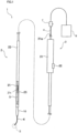
- a stent delivery device 1 schematically includes an elongated catheter 2 which is inserted into a patient's body (lumen) through a treatment instrument guide tube of an endoscope (not illustrated), an operation unit 3 which is connected to a proximal end side of the catheter 2 and operates the catheter 2 inside a body from the outside of the body, a guiding elongated body 4, a stent 5 which is an indwelling target, and a distal end tip 10.
- the vicinity of the distal end of the catheter 2 including the stent 5 may be curved depending on the shape of the site to be indwelled, it is drawn linearly for convenience of the drawing.
- the catheter 2 includes an inner sheath 21 which includes a distal end and a proximal end and an outer sheath 22 which includes a distal end and a proximal end. As illustrated in Fig. 1 , the inner sheath 21 is inserted through the lumen of the outer sheath 22 so as to be slidable.
- a contrast marker (not illustrated) is attached to the vicinity of the distal ends of the inner sheath 21 and the outer sheath 22.
- the contrast marker is a marker of which a position is detected by X-ray fluoroscopy and becomes a marker in the body.
- the contrast marker is formed of a metal material such as gold, platinum, and tungsten or a polymer blended with barium sulfate or bismuth oxide.
- the inner sheath 21 is formed as an elongated tube having flexibility and the guiding elongated body 4 serving as a guide for inserting the catheter 2 into a patient's body is inserted through an inner lumen 21c which is a lumen thereof.
- the distal end of the catheter 2 can be inserted into a target site inside the body as the catheter 2 is pushed (moved forward) along the guiding elongated body 4 after the guiding elongated body 4 is inserted into the body to secure a path inside and outside the body.
- the outer diameter of the inner sheath 21 (a portion for disposing the stent 5 to be described later) is about 0.5 to 3.5 mm.
- the guiding elongated body 4 includes a variable tip area 45 and has another function of puncturing a wall of an organ as well as a function of guiding the catheter 2 as in a normal guide wire.
- the variable tip area 45 and other functions of the guiding elongated body 4 will be described later.
- the catheter 2 may be inserted into the inner lumen 21c by exchanging a guide wire, a dilator, or another tube with the guiding elongated body 4.
- a fixing ring 25 is integrally fixed to the vicinity of the distal end of the inner sheath 21.
- the fixing ring 25 is used to define the position of the proximal end of the stent 5 and a gap between the inner sheath 21 and the outer sheath 22 in a portion from the fixing ring 25 to the distal end becomes a stent placement portion.
- the stent 5 is disposed in the stent placement portion.
- a proximal end side portion in relation to the fixing ring 25 in the inner sheath 21 is provided with another elongated tube (not illustrated) coaxially provided to cover an elongated tube constituting a body of the inner sheath 21 and a proximal end side portion in relation to the fixing ring 25 in the inner sheath 21 is thicker than a distal end side portion in relation to the fixing ring 25 in the inner sheath 21.
- the proximal end side portion in relation to the fixing ring 25 in the inner sheath 21 is thick, the pushability of the inner sheath 21 increases. Accordingly, the operability becomes satisfactory and the deviation of the position of the fixing ring 25 toward the proximal end side is prevented.
- various resin materials including polyolefins such as polyethylene and polypropylene, polyvinyl chloride, polyurethane, ethylene-vinyl acetate copolymer, polyester such as polyethylene terephthalate and polybutylene terephthalate, polyamide, polyether polyamide, polyester polyamide, polyether ether ketone, polyether imide and fluorine-based resins such as polytetrafluoroethylene and tetrafluoroethylene/hexafluoropropylene copolymer, or various thermoplastic elastomers such as polystyrene based elastomers, polyolefin based elastomers, polyurethane based elastomers, polyester based elastomers, polyamide based elastomers, and polybutadiene based elastomers can be used.
- polyolefins such as polyethylene and polypropylene, polyvinyl chloride, polyurethane, ethylene-viny
- the inner sheath 21 and the outer sheath 22 may be respectively provided with reinforcing materials formed in a blade shape or a coil shape by a wire formed of metal such as stainless steel or tungsten or high-rigidity resin such as liquid crystal polymer.
- an outermost tube may be coaxially disposed on the outside of the outer sheath 22.
- the outermost tube is formed as an elongated tube having flexibility and includes a lumen into which the outer sheath 22 is slidably inserted.
- As the outermost tube one having a size larger than the outer diameter of the outer sheath 22 by about 0.05 to 1.0 mm can be used.
- As the material of the outermost tube polyacetal, polytetrafluoroethylene, tetrafluoroethylene/hexafluoropropylene copolymer, polypropylene, or the like can be used.
- the operation unit 3 connected to the proximal end of the stent 5 includes a substantially cylindrical release handle (housing) 31, a distal end lid member having a penetration hole formed at the center portion is integrally attached to the distal end side opening of the release handle 31 so as to close the opening, and a proximal end lid member having a penetration hole formed at the center portion thereof is integrally attached to the proximal end side opening so as to close the opening.
- the proximal end of the inner sheath 21 inserted through the outer sheath 22 passes through the release handle 31 and penetrates the penetration hole of the proximal end lid member of the release handle 31 so that its proximal end is located outside the release handle 31.
- the inner sheath 21 is fixed to the proximal end lid member (the release handle 31) at the penetration hole portion.
- the distal end of the outer sheath 22 reaches the distal end tip 10. Accordingly, in the stent delivery device 1, the stent 5 is held inside the outer sheath 22 while being contracted at the stent placement portion of the inner sheath 21.
- the release lever 32 is moved to the proximal end side of the groove from this state, the outer sheath 22 is slid to the proximal end side with respect to the inner sheath 21 so that the stent 5 is relatively pushed out from the distal end of the outer sheath 22 and the stent 5 is released (expanded) by the self-expanding force.
- the guiding elongated body 4 can be used as a guide for inserting the catheter 2 into the patient's body as illustrated in Fig. 1 .
- the guiding elongated body 4 is inserted through the inner lumen 21c of the inner sheath 21 and is disposed so that its distal end protrudes from the opening of the distal end of the distal end tip 10 of the inner sheath 21 and its proximal end is exposed to the outside through a proximal end opening 21a of the inner sheath 21 disposed to penetrate the operation unit 3.
- the outer diameter of the guiding elongated body 4 can be set to about 0.025 inch ( ⁇ 0.635 mm) to 0.035 inch ( ⁇ 0.889 mm) similarly to the diameter of the general guide wire.
- the guiding elongated body 4 may have an outer diameter in which the inner sheath 21 can be inserted and may have an outer diameter different from the diameter of the general guide wire.
- Fig. 2 is a perspective view illustrating a distal end portion of the guiding elongated body 4 illustrated in Fig. 1 .
- the guiding elongated body 4 has a double tube structure including an inner elongated body 41 which is a tubular body having an innermost lumen 41c formed therein and an outer tube 42 through which the inner elongated body 41 is slidably inserted. Further, an elongated body distal end tip 43 is provided at the distal end of the guiding elongated body 4.
- the elongated body distal end tip 43 includes an electrode 43a cauterizing a wall of an organ and constitutes a puncturing portion capable of puncturing the wall of the organ.
- the elongated body distal end tip 43 has a truncated conical tip shape and the electrode 43a is formed so as to surround an elongated body distal end opening 4c formed in the upper end surface of the truncated cone.
- An electric potential is transmitted to the electrode 43a through a wire 44, but when the inner elongated body 41 or the outer tube 42 is a sheath of a conductive material, these members can be used as the wire 44.
- the electrode 43a illustrated in Fig. 2 is a monopolar type, but the electrode 43a of the elongated body distal end tip 43 may be a bipolar type.
- the elongated body distal end opening 4c illustrated in Fig. 2 communicates with the innermost lumen 41c of the inner elongated body 41.
- the guiding elongated body 4 can flush the contrast agent introduced into the innermost lumen 41c from the proximal end side of the inner elongated body 41 into the body from the elongated body distal end opening 4c.
- a coil tube formed by spirally winding a metal wire such as a stainless steel wire, a flexible metal pipe formed by cutting a metal pipe by laser beam processing or etching, a resin tube formed of PTFE or other resin, and the like can be used.
- the elongated body distal end tip 43 can be formed by the electrode 43a, the wire 44, and resin covering them.
- the proximal end of the guiding elongated body 4 is exposed from the inner lumen 21c through the proximal end opening 21a of the inner sheath 21 and is connected to a slide operation unit 7.
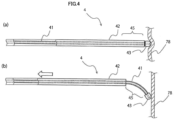
- the slide operation unit 7 is an operation unit for changing the flexibility of the variable tip area (see Fig. 4 ) of the guiding elongated body 4.
- the operator operates a lever provided in the slide operation unit 7 so as to move the outer tube 42 and the inner elongated body 41 illustrated in Figs. 2 and 4 in the axial direction. Accordingly, the flexibility of the variable tip area 45 can be easily and rapidly changed between a first state and a second state.
- a wiring cord connected to a generator 8 supplying power to the wire 44 of the guiding elongated body 4 is connected to the slide operation unit 7 and an electric potential is transmitted from the proximal end of the guiding elongated body 4 to the electrode 43a provided in the distal end of the guiding elongated body 4.
- Fig. 4(a) is a side view illustrating the second state of the variable tip area 45 of the guiding elongated body 4
- Fig. 4(b) is a side view illustrating the first state of the variable tip area 45.
- the guiding elongated body 4 includes the variable tip area 45 which is provided in the vicinity of the distal end of the guiding elongated body 4, and the variable tip area 45 has an ability of changing the flexibility by the operation of the slide operation unit 7 connected to the proximal end.
- the inner elongated body 41 is exposed from the distal end of the outer tube 42.
- variable tip area 45 of the guiding elongated body 4 when the variable tip area 45 of the guiding elongated body 4 is in the first state, the inner elongated body 41 is exposed from the distal end of the outer tube 42 and the exposure length is a first length. As illustrated in Fig. 4(b) , the variable tip area 45 in the first state has predetermined flexibility. When the distal end of the guiding elongated body 4 contacts a wall of an organ 78, the variable tip area 45 is easily bent and the distal end of the guiding elongated body 4 moves along the wall of the organ 78.
- the flexibility of the variable tip area 45 in the first state is the same as the flexibility of the inner elongated body 41 alone exposed from the outer tube 42 and, for example, the flexibility of the inner elongated body 41 can be set to be substantially the same as that of the general guide wire.
- the exposure length in which the inner elongated body 41 is exposed from the distal end of the outer tube 42 is a second length shorter than the first length in the first state.
- a state in which the exposure length is the second length includes a state in which the inner elongated body 41 is not exposed from the distal end of the outer tube 42 (a state in which the exposure length is 0).
- the variable tip area 45 in the second state is stiffer than the first state. Even when the distal end of the guiding elongated body 4 contacts a wall of an organ, the variable tip area 45 is not easily bent and the distal end of the guiding elongated body 4 can be pressed against the wall of the organ.
- the flexibility of the variable tip area 45 in the second state is the same as the flexibility of the proximal end side portion in relation to the variable tip area 45 of the guiding elongated body 4 (a portion in which the outer tube 42 and the inner elongated body 41 with the innermost lumen 41c are double tubes).
- the flexibility of the portion in which the outer tube 42 and the inner elongated body 41 are double tubes can be set to the flexibility lower than that of the general guide wire.
- the distal end portion of the inner elongated body 41 is provided with a precurved bending and the bending is corrected by the rigidity of the outer tube 42 in the outer tube 42 so that the distal end portion of the inner elongated body 41 has a linear shape. When the distal end portion is exposed from the outer tube 42, the distal end portion of the inner elongated body 41 may be curved due to the bending.
- the stent delivery device 1 including the guiding elongated body 4 changes the flexibility of the variable tip area 45 of the guiding elongated body 4 depending on the internal body condition in the vicinity of the distal end of the stent delivery device 1 or the procedure thereof, it is possible to shorten the time necessary for the procedure and to rapidly transport and indwell the stent 5 to the indwelling site.
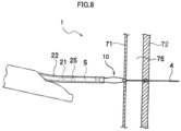
- Fig. 8 illustrates one procedure using the stent delivery device 1 and illustrates a procedure of puncturing a stomach wall 71 and a bile duct wall 72 interposing an abdominal cavity 75 therebetween.
- the electrode 43a (see Fig. 2 ) provided in the distal end of the guiding elongated body 4 is pressed against the stomach wall 71 and cauterizes and punctures the stomach wall 71.
- the guiding elongated body 4 when the guiding elongated body 4 is further pushed outward while the variable tip area 45 is maintained in the second state in which the variable tip area is stiffer and hardly bent, the guiding elongated body 4 penetrates the punctured hole of the stomach wall 71 so that the distal end of the guiding elongated body 4 reaches the bile duct wall 72. Further, when the bile duct wall 72 is also punctured similarly to the stomach wall 71 and the guiding elongated body 4 is pushed inward while the variable tip area 45 is maintained in the second state, the guiding elongated body 4 can be located inside a bile duct 76.
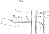
- Fig. 9 is a diagram illustrating another procedure using the stent delivery device 1 and illustrating a procedure performed after the procedure illustrated in Fig. 8 .
- the guiding elongated body 4 is set to the first state.
- the distal end of the guiding elongated body 4 can be moved to the indwelling position of the stent 5 inside the bile duct 76 along the bile duct wall 72 (the inner wall).
- the catheter 2 is inserted into the bile duct 76 along the guiding elongated body 4 and the stent 5 can be transported and indwelled to the indwelling position.
- the electrode 43a located at the distal end of the guiding elongated body 4 can be strongly pressed against the punctured site and hence the puncturing can be rapidly performed. Further, if the variable tip area 45 of the guiding elongated body 4 is set to the first state when the puncturing is not performed, it is possible to prevent the distal end of the guiding elongated body 4 from being strongly pressed against a wall of an organ, such as the bile duct wall 72 or the like.
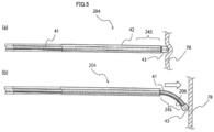
- Fig. 6(a) is a side view illustrating a second state of a variable tip area 345 of a guiding elongated body 304 of a stent delivery device according to a third embodiment of the invention
- Fig. 6(b) is a side view illustrating a first state of the variable tip area 345.
- the stent delivery device according to the third embodiment is the same as the stent delivery device 1 according to the first embodiment except that the structure of the distal end portion of the guiding elongated body 304 is different.
- the description of the stent delivery device according to the third embodiment only the different points from the stent delivery device 1 will be described and the description of the common points with the stent delivery device 1 will be omitted.
- the guiding elongated body 304 includes an inner elongated body 341 which is a wire, an outer tube 342 through which the inner elongated body 341 is slidably inserted, and an elongated body distal end tip 343.
- the elongated body distal end tip 343 is different from the elongated body distal end tip 43 according to the first embodiment in that the elongated body distal end tip is connected to the outer tube 342, but is the same as the elongated body distal end tip 43 illustrated in Fig. 2 in that the elongated body distal end tip includes the electrode 43a.
- a non-overlapping length in which the outer tube 342 does not overlap the inner elongated body 341 is a fourth length shorter than the third length in the first state.
- a state in which the non-overlapping length is the fourth length includes a state in which the inner elongated body 341 matches the distal end of the outer tube 342 (a state in which the non-overlapping length is 0).
- the variable tip area 345 corresponding to the second state illustrated in Fig. 6(a) is stiffer than the variable tip area 345 corresponding to the first state illustrated in Fig.
- the inner elongated body 341 is desirably a wire not including a lumen formed therein.
- a wire formed of metal such as stainless steel can be used.
- variable tip area 345 of the guiding elongated body 304 changes from the second state illustrated in Fig. 6(a) to the first state illustrated in Fig. 6(b) .
- the stent delivery device according to the third embodiment with such a guiding elongated body 304 has the same effect as that of the stent delivery device 1 according to the first embodiment.
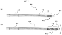
- the guiding elongated body 404 includes an inner elongated body 441, an outer tube 442 through which the inner elongated body 441 is slidably inserted, and an elongated body distal end tip 443. Since the elongated body distal end tip 443 is connected to both of the inner elongated body 441 and the outer tube 442, this elongated body distal end tip is different from the elongated body distal end tip 43 according to the first embodiment, but is the same as the elongated body distal end tip 43 illustrated in Fig. 2 in that the electrode 43a is provided.
- the outer tube 442 includes a telescopic distal end portion 442a provided in the vicinity of the distal end of the outer tube 442 and having elasticity in the axial direction while changing the flexibility.
- the telescopic distal end portion 442a is formed as a coil tube formed of a metal wire so that a tube wall is spirally wound.
- the telescopic distal end portion 442a of the outer tube 442 is expanded in the axial direction. Accordingly, the flexibility of the telescopic distal end portion 442a is higher than that of the second state in which the telescopic distal end portion 442a is contracted.
- Fig. 10(a) is a side view illustrating a second state of a variable tip area 545 of a guiding elongated body 504 of a stent delivery device according to a second modified example of the invention
- Fig. 10(b) is a side view illustrating a first state of the variable tip area 545.
- the stent delivery device according to the second modified example is the same as the stent delivery device according to the third embodiment illustrated in Figs. 6(a) and 6(b) except that the guiding elongated body 504 includes a covering tube 511.
- the description of the stent delivery device according to the second modified example only the different points from the stent delivery device according to the third embodiment will be described and the description of the common points with the stent delivery device according to the third embodiment will be omitted.
Landscapes
- Health & Medical Sciences (AREA)
- Engineering & Computer Science (AREA)
- Biomedical Technology (AREA)
- Life Sciences & Earth Sciences (AREA)
- Animal Behavior & Ethology (AREA)
- Veterinary Medicine (AREA)
- Public Health (AREA)
- Heart & Thoracic Surgery (AREA)
- General Health & Medical Sciences (AREA)
- Transplantation (AREA)
- Vascular Medicine (AREA)
- Oral & Maxillofacial Surgery (AREA)
- Cardiology (AREA)
- Surgery (AREA)
- Physics & Mathematics (AREA)
- Plasma & Fusion (AREA)
- Nuclear Medicine, Radiotherapy & Molecular Imaging (AREA)
- Otolaryngology (AREA)
- Medical Informatics (AREA)
- Molecular Biology (AREA)
- Media Introduction/Drainage Providing Device (AREA)
- Surgical Instruments (AREA)
Claims (7)
- Eine Stent-Einführvorrichtung (1), umfassend:einen Katheter (2) aufweisend eine innere Hülse (21) und eine äußere Hülse (22) zum Ermöglichen, die innere Hülse (21) dadurch gleitend eingeführt zu werden,einen Stent (5), der zwischen der inneren Hülle (21) und der äußeren Hülle (22) in der Nähe eines distalen Endes des Katheters (2) vorgesehen ist; undeinen länglichen Führungskörper (4, 104, 204, 304, 404, 504), der durch ein inneres Lumen (21c) der inneren Hülle (21) eingeführt ist und fähig ist, teilweise vom distalen Ende des Katheters (2) freigelegt zu werden, um das Einführen des Katheters (2) zu führen,wobei der längliche Führungskörper (4, 104, 204, 304, 404, 504) einen inneren länglichen Körper (41, 341, 441) und ein äußeres Rohr (42, 342, 442) umfasst, durch das der innere längliche Körper (41, 341, 441) gleitend eingeführt wird, und einen variablen Spitzenbereich (45, 245, 345, 445, 545) aufweist, der in der Nähe eines distalen Endes des länglichen Führungskörpers (4, 104, 204, 304, 404, 504) vorgesehen ist, undwobei der variable Spitzenbereich (45, 245, 345, 445, 545) eine Fähigkeit hat, die Flexibilität zwischen einem ersten Zustand, in dem der variable Spitzenbereich (45, 245, 345, 445, 545) eine vorbestimmte Flexibilität hat, und einem zweiten Zustand, in dem der variable Spitzenbereich (45, 245, 345, 445, 545) steifer als der erste Zustand ist, zu ändern, indem der innere längliche Körper (41, 341, 441) und das äußere Rohr (42, 342, 442) in einer axialen Richtung relativ bewegt werden.
- Die Stent-Einführvorrichtung (1) nach Anspruch 1,
wobei der längliche Führungskörper (4, 104) einen Punktionsabschnitt (43a, 143a) aufweist, der im distalen Ende des länglichen Führungskörpers (4, 104) vorgesehen ist, um eine Wand eines Organs zu punktieren. - Die Stent-Einführvorrichtung (1) nach Anspruch 2,
wobei der Punktionsabschnitt eine Elektrode (43a) zum Kauterisieren einer Wand eines Organs aufweist. - Die Stent-Einführvorrichtung (1) nach einem der Ansprüche 1 bis 3,wobei, wenn der variable Spitzenbereich (45) in dem ersten Zustand ist, eine Freilegungslänge, in der der innere längliche Körper (41) von einem distalen Ende des äußeren Rohrs (42) freigelegt ist, eine erste Länge ist, undwobei, wenn der variable Spitzenbereich (45) im zweiten Zustand ist, die Expositionslänge eine zweite Länge ist, die kürzer als die erste Länge ist.
- Die Stent-Einführvorrichtung (1) nach einem der Ansprüche 1 bis 3,wobei, wenn sich der variable Spitzenbereich (45, 245, 345, 545) im ersten Zustand befindet, eine nicht überlappende Länge, in der das äußere Rohr (42, 342) und der innere längliche Körper (41, 341) einander in der Nähe des distalen Endes des länglichen Führungskörpers (4, 104, 204, 304, 504) nicht überlappen, eine dritte Länge ist, undwobei, wenn sich der variable Spitzenbereich (45, 245, 345, 545) im zweiten Zustand befindet, die nicht überlappende Länge eine vierte Länge kürzer als die dritte Länge ist.
- Die Stent-Einführvorrichtung (1) nach einem der Ansprüche 1 bis 3,
wobei das äußere Rohr (442) einen teleskopischen distalen Endabschnitt (442a) enthält, der in der Nähe eines distalen Endes des äußeren Rohrs (442) vorgesehen ist und Elastizität in einer axialen Richtung beim Ändern der Flexibilität aufweist. - Die Stent-Einführvorrichtung (1) nach einem der Ansprüche 1 bis 6, weiterhin aufweisend:einen Betätigungsdraht (206), der mit dem distalen Ende des länglichen Führungskörpers (204) verbunden ist und durch das innere Lumen (21c) der inneren Hülle (21) parallel zu dem länglichen Führungskörper (204) eingeführt wird,wobei der Betätigungsdraht (206) verwendet wird, um das Biegen und das Dehnen in der Nähe (245) des distalen Endes des länglichen Führungskörpers (204) zu betreiben.
Applications Claiming Priority (2)
| Application Number | Priority Date | Filing Date | Title |
|---|---|---|---|
| JP2017072834 | 2017-03-31 | ||
| PCT/JP2018/012453 WO2018181326A1 (ja) | 2017-03-31 | 2018-03-27 | ステントデリバリー装置 |
Publications (3)
| Publication Number | Publication Date |
|---|---|
| EP3603586A1 EP3603586A1 (de) | 2020-02-05 |
| EP3603586A4 EP3603586A4 (de) | 2020-12-16 |
| EP3603586B1 true EP3603586B1 (de) | 2023-12-20 |
Family
ID=63675841
Family Applications (1)
| Application Number | Title | Priority Date | Filing Date |
|---|---|---|---|
| EP18776684.5A Active EP3603586B1 (de) | 2017-03-31 | 2018-03-27 | Stenteinführvorrichtung |
Country Status (5)
| Country | Link |
|---|---|
| US (2) | US11458031B2 (de) |
| EP (1) | EP3603586B1 (de) |
| JP (1) | JP7120221B2 (de) |
| CN (1) | CN110381896B (de) |
| WO (1) | WO2018181326A1 (de) |
Families Citing this family (6)
| Publication number | Priority date | Publication date | Assignee | Title |
|---|---|---|---|---|
| EP0766395A3 (de) | 1995-09-27 | 1999-04-21 | Siemens Aktiengesellschaft | Leistungstransistor mit Kurzschlussschutz |
| CN113825537B (zh) * | 2019-05-07 | 2023-10-31 | 朝日英达科株式会社 | 导丝 |
| EP3941378B1 (de) * | 2019-07-30 | 2025-05-21 | Boston Scientific Scimed, Inc. | Elektrochirurgische spitze |
| WO2022245921A1 (en) * | 2021-05-19 | 2022-11-24 | Boston Scientific Scimed, Inc. | Lumen apposing stent to deliver targeted therapy |
| CN115869534B (zh) * | 2021-09-29 | 2023-11-21 | 江苏畅医达医疗科技有限公司 | 一种植入电极及其外周神经刺激系统 |
| US12453844B2 (en) | 2023-09-22 | 2025-10-28 | JMT Medical, Inc. | Devices and methods for bile duct surgery |
Family Cites Families (23)
| Publication number | Priority date | Publication date | Assignee | Title |
|---|---|---|---|---|
| US4873983A (en) | 1988-01-27 | 1989-10-17 | Advanced Biomedical Devices, Inc. | Steerable guidewire for vascular system |
| US5238005A (en) * | 1991-11-18 | 1993-08-24 | Intelliwire, Inc. | Steerable catheter guidewire |
| US6071274A (en) * | 1996-12-19 | 2000-06-06 | Ep Technologies, Inc. | Loop structures for supporting multiple electrode elements |
| DK176341B1 (da) * | 1996-09-06 | 2007-08-27 | Cook William Europ | Aggregat til transluminal indföring af en rörformet stent, og en endovaskulær graftindretning |
| US7163552B2 (en) * | 2000-10-13 | 2007-01-16 | Medtronic Vascular, Inc. | Stent delivery system with hydraulic deployment |
| WO2003043685A2 (en) * | 2001-11-19 | 2003-05-30 | Cardiovascular Systems, Inc | High torque, low profile intravascular guidewire system |
| US20030171642A1 (en) * | 2002-03-05 | 2003-09-11 | Schock Robert B. | Intra-aortic balloon catheter having a releasable guide wire |
| US20070167804A1 (en) * | 2002-09-18 | 2007-07-19 | Byong-Ho Park | Tubular compliant mechanisms for ultrasonic imaging systems and intravascular interventional devices |
| US7867176B2 (en) * | 2005-12-27 | 2011-01-11 | Cordis Corporation | Variable stiffness guidewire |
| US9387308B2 (en) * | 2007-04-23 | 2016-07-12 | Cardioguidance Biomedical, Llc | Guidewire with adjustable stiffness |
| AU2008244613A1 (en) | 2007-04-23 | 2008-11-06 | Intervention & Surgical Innovations, Llc | Guidewire with adjustable stiffness |
| US8858490B2 (en) * | 2007-07-18 | 2014-10-14 | Silk Road Medical, Inc. | Systems and methods for treating a carotid artery |
| US7713215B2 (en) * | 2008-01-31 | 2010-05-11 | Shriver Edgar L | Steering, piercing, anchoring, distending extravascular guidewire |
| US20090264988A1 (en) * | 2008-04-18 | 2009-10-22 | Medtronic Vascular, Inc. | Stent Graft Delivery System Including Support for Fenestration in Situ and a Mechanism for Modeling |
| IT1391568B1 (it) * | 2008-09-05 | 2012-01-11 | E V R Endovascular Res Es S A | Cavo guida di navigazione attraverso una anatomia con condotti ramificati |
| CN103948419B (zh) * | 2012-05-03 | 2017-01-25 | 徐舒 | 一种穿刺器械 |
| US8986224B2 (en) * | 2012-07-20 | 2015-03-24 | DePuy Synthes Products, LLC | Guidewire with highly flexible tip |
| JP6000806B2 (ja) * | 2012-11-02 | 2016-10-05 | オリンパス株式会社 | ガイドワイヤ |
| JP6163829B2 (ja) | 2013-03-29 | 2017-07-19 | 日本ゼオン株式会社 | カテーテル用先端チップ |
| US10238816B2 (en) * | 2014-01-14 | 2019-03-26 | Volcano Corporation | Devices and methods for forming vascular access |
| JP6775915B2 (ja) | 2015-03-31 | 2020-10-28 | 日本ゼオン株式会社 | ステントデリバリー装置 |
| US10154905B2 (en) | 2015-08-07 | 2018-12-18 | Medtronic Vascular, Inc. | System and method for deflecting a delivery catheter |
| CN206007289U (zh) * | 2016-07-01 | 2017-03-15 | 南京医科大学附属南京儿童医院 | 一种肌部室间隔缺损封堵器输送装置 |
-
2018
- 2018-03-27 EP EP18776684.5A patent/EP3603586B1/de active Active
- 2018-03-27 JP JP2019509893A patent/JP7120221B2/ja active Active
- 2018-03-27 US US16/496,395 patent/US11458031B2/en active Active
- 2018-03-27 CN CN201880015596.9A patent/CN110381896B/zh active Active
- 2018-03-27 WO PCT/JP2018/012453 patent/WO2018181326A1/ja not_active Ceased
-
2022
- 2022-06-03 US US17/805,408 patent/US20220313462A1/en not_active Abandoned
Also Published As
| Publication number | Publication date |
|---|---|
| US20210106448A1 (en) | 2021-04-15 |
| EP3603586A1 (de) | 2020-02-05 |
| US11458031B2 (en) | 2022-10-04 |
| WO2018181326A1 (ja) | 2018-10-04 |
| JPWO2018181326A1 (ja) | 2020-02-06 |
| CN110381896B (zh) | 2022-09-13 |
| JP7120221B2 (ja) | 2022-08-17 |
| EP3603586A4 (de) | 2020-12-16 |
| CN110381896A (zh) | 2019-10-25 |
| US20220313462A1 (en) | 2022-10-06 |
Similar Documents
| Publication | Publication Date | Title |
|---|---|---|
| EP3603586B1 (de) | Stenteinführvorrichtung | |
| JP6775915B2 (ja) | ステントデリバリー装置 | |
| US20220096801A1 (en) | Vascular access devices and methods | |
| US9539055B2 (en) | Resection device with support mechanism and related methods of use | |
| CN110302465B (zh) | 用于将物质递送到解剖结构的器械 | |
| CN111067588A (zh) | 导管 | |
| US20220378593A1 (en) | Stent delivery system, endoscope system, and stent indwelling method | |
| US9554821B2 (en) | Resection device with support mechanism and related methods of use | |
| US11564788B1 (en) | Single site access aortic aneurysm repair method | |
| JP6805481B2 (ja) | カテーテルおよびステントデリバリ装置 | |
| JP6589337B2 (ja) | ステントデリバリー装置 | |
| WO2019198210A1 (ja) | カテーテル | |
| JP6904385B2 (ja) | ステントデリバリー装置 | |
| CN110785204B (zh) | 可取回的接入阀 | |
| EP3909513B1 (de) | Endoskopische punktionsvorrichtung | |
| JP6672604B2 (ja) | チューブステント | |
| US12589015B2 (en) | Stent delivery system, endoscope system, and stent indwelling method | |
| JP2017176277A (ja) | 医療用デバイス | |
| JP2023129895A (ja) | カテーテル |
Legal Events
| Date | Code | Title | Description |
|---|---|---|---|
| STAA | Information on the status of an ep patent application or granted ep patent |
Free format text: STATUS: THE INTERNATIONAL PUBLICATION HAS BEEN MADE |
|
| PUAI | Public reference made under article 153(3) epc to a published international application that has entered the european phase |
Free format text: ORIGINAL CODE: 0009012 |
|
| STAA | Information on the status of an ep patent application or granted ep patent |
Free format text: STATUS: REQUEST FOR EXAMINATION WAS MADE |
|
| 17P | Request for examination filed |
Effective date: 20190923 |
|
| AK | Designated contracting states |
Kind code of ref document: A1 Designated state(s): AL AT BE BG CH CY CZ DE DK EE ES FI FR GB GR HR HU IE IS IT LI LT LU LV MC MK MT NL NO PL PT RO RS SE SI SK SM TR |
|
| AX | Request for extension of the european patent |
Extension state: BA ME |
|
| DAV | Request for validation of the european patent (deleted) | ||
| DAX | Request for extension of the european patent (deleted) | ||
| A4 | Supplementary search report drawn up and despatched |
Effective date: 20201113 |
|
| RIC1 | Information provided on ipc code assigned before grant |
Ipc: A61F 2/962 20130101AFI20201109BHEP Ipc: A61B 18/14 20060101ALI20201109BHEP Ipc: A61F 2/966 20130101ALI20201109BHEP |
|
| GRAP | Despatch of communication of intention to grant a patent |
Free format text: ORIGINAL CODE: EPIDOSNIGR1 |
|
| STAA | Information on the status of an ep patent application or granted ep patent |
Free format text: STATUS: GRANT OF PATENT IS INTENDED |
|
| RIC1 | Information provided on ipc code assigned before grant |
Ipc: A61F 2/966 20130101ALI20230704BHEP Ipc: A61B 18/14 20060101ALI20230704BHEP Ipc: A61F 2/962 20130101AFI20230704BHEP |
|
| INTG | Intention to grant announced |
Effective date: 20230804 |
|
| GRAS | Grant fee paid |
Free format text: ORIGINAL CODE: EPIDOSNIGR3 |
|
| GRAA | (expected) grant |
Free format text: ORIGINAL CODE: 0009210 |
|
| STAA | Information on the status of an ep patent application or granted ep patent |
Free format text: STATUS: THE PATENT HAS BEEN GRANTED |
|
| P01 | Opt-out of the competence of the unified patent court (upc) registered |
Effective date: 20231017 |
|
| AK | Designated contracting states |
Kind code of ref document: B1 Designated state(s): AL AT BE BG CH CY CZ DE DK EE ES FI FR GB GR HR HU IE IS IT LI LT LU LV MC MK MT NL NO PL PT RO RS SE SI SK SM TR |
|
| REG | Reference to a national code |
Ref country code: GB Ref legal event code: FG4D |
|
| REG | Reference to a national code |
Ref country code: CH Ref legal event code: EP |
|
| REG | Reference to a national code |
Ref country code: DE Ref legal event code: R096 Ref document number: 602018062940 Country of ref document: DE |
|
| REG | Reference to a national code |
Ref country code: IE Ref legal event code: FG4D |
|
| PG25 | Lapsed in a contracting state [announced via postgrant information from national office to epo] |
Ref country code: GR Free format text: LAPSE BECAUSE OF FAILURE TO SUBMIT A TRANSLATION OF THE DESCRIPTION OR TO PAY THE FEE WITHIN THE PRESCRIBED TIME-LIMIT Effective date: 20240321 |
|
| REG | Reference to a national code |
Ref country code: LT Ref legal event code: MG9D |
|
| PG25 | Lapsed in a contracting state [announced via postgrant information from national office to epo] |
Ref country code: LT Free format text: LAPSE BECAUSE OF FAILURE TO SUBMIT A TRANSLATION OF THE DESCRIPTION OR TO PAY THE FEE WITHIN THE PRESCRIBED TIME-LIMIT Effective date: 20231220 |
|
| REG | Reference to a national code |
Ref country code: NL Ref legal event code: MP Effective date: 20231220 |
|
| PG25 | Lapsed in a contracting state [announced via postgrant information from national office to epo] |
Ref country code: ES Free format text: LAPSE BECAUSE OF FAILURE TO SUBMIT A TRANSLATION OF THE DESCRIPTION OR TO PAY THE FEE WITHIN THE PRESCRIBED TIME-LIMIT Effective date: 20231220 |
|
| PG25 | Lapsed in a contracting state [announced via postgrant information from national office to epo] |
Ref country code: LT Free format text: LAPSE BECAUSE OF FAILURE TO SUBMIT A TRANSLATION OF THE DESCRIPTION OR TO PAY THE FEE WITHIN THE PRESCRIBED TIME-LIMIT Effective date: 20231220 Ref country code: GR Free format text: LAPSE BECAUSE OF FAILURE TO SUBMIT A TRANSLATION OF THE DESCRIPTION OR TO PAY THE FEE WITHIN THE PRESCRIBED TIME-LIMIT Effective date: 20240321 Ref country code: FI Free format text: LAPSE BECAUSE OF FAILURE TO SUBMIT A TRANSLATION OF THE DESCRIPTION OR TO PAY THE FEE WITHIN THE PRESCRIBED TIME-LIMIT Effective date: 20231220 Ref country code: ES Free format text: LAPSE BECAUSE OF FAILURE TO SUBMIT A TRANSLATION OF THE DESCRIPTION OR TO PAY THE FEE WITHIN THE PRESCRIBED TIME-LIMIT Effective date: 20231220 Ref country code: BG Free format text: LAPSE BECAUSE OF FAILURE TO SUBMIT A TRANSLATION OF THE DESCRIPTION OR TO PAY THE FEE WITHIN THE PRESCRIBED TIME-LIMIT Effective date: 20240320 |
|
| REG | Reference to a national code |
Ref country code: AT Ref legal event code: MK05 Ref document number: 1641853 Country of ref document: AT Kind code of ref document: T Effective date: 20231220 |
|
| PG25 | Lapsed in a contracting state [announced via postgrant information from national office to epo] |
Ref country code: NL Free format text: LAPSE BECAUSE OF FAILURE TO SUBMIT A TRANSLATION OF THE DESCRIPTION OR TO PAY THE FEE WITHIN THE PRESCRIBED TIME-LIMIT Effective date: 20231220 |
|
| PG25 | Lapsed in a contracting state [announced via postgrant information from national office to epo] |
Ref country code: SE Free format text: LAPSE BECAUSE OF FAILURE TO SUBMIT A TRANSLATION OF THE DESCRIPTION OR TO PAY THE FEE WITHIN THE PRESCRIBED TIME-LIMIT Effective date: 20231220 Ref country code: RS Free format text: LAPSE BECAUSE OF FAILURE TO SUBMIT A TRANSLATION OF THE DESCRIPTION OR TO PAY THE FEE WITHIN THE PRESCRIBED TIME-LIMIT Effective date: 20231220 Ref country code: NO Free format text: LAPSE BECAUSE OF FAILURE TO SUBMIT A TRANSLATION OF THE DESCRIPTION OR TO PAY THE FEE WITHIN THE PRESCRIBED TIME-LIMIT Effective date: 20240320 Ref country code: NL Free format text: LAPSE BECAUSE OF FAILURE TO SUBMIT A TRANSLATION OF THE DESCRIPTION OR TO PAY THE FEE WITHIN THE PRESCRIBED TIME-LIMIT Effective date: 20231220 Ref country code: LV Free format text: LAPSE BECAUSE OF FAILURE TO SUBMIT A TRANSLATION OF THE DESCRIPTION OR TO PAY THE FEE WITHIN THE PRESCRIBED TIME-LIMIT Effective date: 20231220 Ref country code: HR Free format text: LAPSE BECAUSE OF FAILURE TO SUBMIT A TRANSLATION OF THE DESCRIPTION OR TO PAY THE FEE WITHIN THE PRESCRIBED TIME-LIMIT Effective date: 20231220 |
|
| PG25 | Lapsed in a contracting state [announced via postgrant information from national office to epo] |
Ref country code: IS Free format text: LAPSE BECAUSE OF FAILURE TO SUBMIT A TRANSLATION OF THE DESCRIPTION OR TO PAY THE FEE WITHIN THE PRESCRIBED TIME-LIMIT Effective date: 20240420 |
|
| PG25 | Lapsed in a contracting state [announced via postgrant information from national office to epo] |
Ref country code: CZ Free format text: LAPSE BECAUSE OF FAILURE TO SUBMIT A TRANSLATION OF THE DESCRIPTION OR TO PAY THE FEE WITHIN THE PRESCRIBED TIME-LIMIT Effective date: 20231220 Ref country code: AT Free format text: LAPSE BECAUSE OF FAILURE TO SUBMIT A TRANSLATION OF THE DESCRIPTION OR TO PAY THE FEE WITHIN THE PRESCRIBED TIME-LIMIT Effective date: 20231220 |
|
| PG25 | Lapsed in a contracting state [announced via postgrant information from national office to epo] |
Ref country code: SK Free format text: LAPSE BECAUSE OF FAILURE TO SUBMIT A TRANSLATION OF THE DESCRIPTION OR TO PAY THE FEE WITHIN THE PRESCRIBED TIME-LIMIT Effective date: 20231220 |
|
| PG25 | Lapsed in a contracting state [announced via postgrant information from national office to epo] |
Ref country code: SM Free format text: LAPSE BECAUSE OF FAILURE TO SUBMIT A TRANSLATION OF THE DESCRIPTION OR TO PAY THE FEE WITHIN THE PRESCRIBED TIME-LIMIT Effective date: 20231220 Ref country code: SK Free format text: LAPSE BECAUSE OF FAILURE TO SUBMIT A TRANSLATION OF THE DESCRIPTION OR TO PAY THE FEE WITHIN THE PRESCRIBED TIME-LIMIT Effective date: 20231220 Ref country code: RO Free format text: LAPSE BECAUSE OF FAILURE TO SUBMIT A TRANSLATION OF THE DESCRIPTION OR TO PAY THE FEE WITHIN THE PRESCRIBED TIME-LIMIT Effective date: 20231220 Ref country code: IT Free format text: LAPSE BECAUSE OF FAILURE TO SUBMIT A TRANSLATION OF THE DESCRIPTION OR TO PAY THE FEE WITHIN THE PRESCRIBED TIME-LIMIT Effective date: 20231220 Ref country code: IS Free format text: LAPSE BECAUSE OF FAILURE TO SUBMIT A TRANSLATION OF THE DESCRIPTION OR TO PAY THE FEE WITHIN THE PRESCRIBED TIME-LIMIT Effective date: 20240420 Ref country code: EE Free format text: LAPSE BECAUSE OF FAILURE TO SUBMIT A TRANSLATION OF THE DESCRIPTION OR TO PAY THE FEE WITHIN THE PRESCRIBED TIME-LIMIT Effective date: 20231220 Ref country code: CZ Free format text: LAPSE BECAUSE OF FAILURE TO SUBMIT A TRANSLATION OF THE DESCRIPTION OR TO PAY THE FEE WITHIN THE PRESCRIBED TIME-LIMIT Effective date: 20231220 Ref country code: AT Free format text: LAPSE BECAUSE OF FAILURE TO SUBMIT A TRANSLATION OF THE DESCRIPTION OR TO PAY THE FEE WITHIN THE PRESCRIBED TIME-LIMIT Effective date: 20231220 |
|
| PG25 | Lapsed in a contracting state [announced via postgrant information from national office to epo] |
Ref country code: PL Free format text: LAPSE BECAUSE OF FAILURE TO SUBMIT A TRANSLATION OF THE DESCRIPTION OR TO PAY THE FEE WITHIN THE PRESCRIBED TIME-LIMIT Effective date: 20231220 Ref country code: PT Free format text: LAPSE BECAUSE OF FAILURE TO SUBMIT A TRANSLATION OF THE DESCRIPTION OR TO PAY THE FEE WITHIN THE PRESCRIBED TIME-LIMIT Effective date: 20240422 |
|
| PG25 | Lapsed in a contracting state [announced via postgrant information from national office to epo] |
Ref country code: PT Free format text: LAPSE BECAUSE OF FAILURE TO SUBMIT A TRANSLATION OF THE DESCRIPTION OR TO PAY THE FEE WITHIN THE PRESCRIBED TIME-LIMIT Effective date: 20240422 Ref country code: PL Free format text: LAPSE BECAUSE OF FAILURE TO SUBMIT A TRANSLATION OF THE DESCRIPTION OR TO PAY THE FEE WITHIN THE PRESCRIBED TIME-LIMIT Effective date: 20231220 |
|
| REG | Reference to a national code |
Ref country code: DE Ref legal event code: R097 Ref document number: 602018062940 Country of ref document: DE |
|
| PG25 | Lapsed in a contracting state [announced via postgrant information from national office to epo] |
Ref country code: DK Free format text: LAPSE BECAUSE OF FAILURE TO SUBMIT A TRANSLATION OF THE DESCRIPTION OR TO PAY THE FEE WITHIN THE PRESCRIBED TIME-LIMIT Effective date: 20231220 |
|
| PLBE | No opposition filed within time limit |
Free format text: ORIGINAL CODE: 0009261 |
|
| STAA | Information on the status of an ep patent application or granted ep patent |
Free format text: STATUS: NO OPPOSITION FILED WITHIN TIME LIMIT |
|
| PG25 | Lapsed in a contracting state [announced via postgrant information from national office to epo] |
Ref country code: SI Free format text: LAPSE BECAUSE OF FAILURE TO SUBMIT A TRANSLATION OF THE DESCRIPTION OR TO PAY THE FEE WITHIN THE PRESCRIBED TIME-LIMIT Effective date: 20231220 |
|
| PG25 | Lapsed in a contracting state [announced via postgrant information from national office to epo] |
Ref country code: SI Free format text: LAPSE BECAUSE OF FAILURE TO SUBMIT A TRANSLATION OF THE DESCRIPTION OR TO PAY THE FEE WITHIN THE PRESCRIBED TIME-LIMIT Effective date: 20231220 Ref country code: DK Free format text: LAPSE BECAUSE OF FAILURE TO SUBMIT A TRANSLATION OF THE DESCRIPTION OR TO PAY THE FEE WITHIN THE PRESCRIBED TIME-LIMIT Effective date: 20231220 |
|
| REG | Reference to a national code |
Ref country code: CH Ref legal event code: PL |
|
| PG25 | Lapsed in a contracting state [announced via postgrant information from national office to epo] |
Ref country code: LU Free format text: LAPSE BECAUSE OF NON-PAYMENT OF DUE FEES Effective date: 20240327 |
|
| PG25 | Lapsed in a contracting state [announced via postgrant information from national office to epo] |
Ref country code: MC Free format text: LAPSE BECAUSE OF FAILURE TO SUBMIT A TRANSLATION OF THE DESCRIPTION OR TO PAY THE FEE WITHIN THE PRESCRIBED TIME-LIMIT Effective date: 20231220 |
|
| 26N | No opposition filed |
Effective date: 20240923 |
|
| PG25 | Lapsed in a contracting state [announced via postgrant information from national office to epo] |
Ref country code: MC Free format text: LAPSE BECAUSE OF FAILURE TO SUBMIT A TRANSLATION OF THE DESCRIPTION OR TO PAY THE FEE WITHIN THE PRESCRIBED TIME-LIMIT Effective date: 20231220 Ref country code: LU Free format text: LAPSE BECAUSE OF NON-PAYMENT OF DUE FEES Effective date: 20240327 |
|
| REG | Reference to a national code |
Ref country code: BE Ref legal event code: MM Effective date: 20240331 |
|
| PG25 | Lapsed in a contracting state [announced via postgrant information from national office to epo] |
Ref country code: BE Free format text: LAPSE BECAUSE OF NON-PAYMENT OF DUE FEES Effective date: 20240331 |
|
| PG25 | Lapsed in a contracting state [announced via postgrant information from national office to epo] |
Ref country code: FR Free format text: LAPSE BECAUSE OF NON-PAYMENT OF DUE FEES Effective date: 20240331 |
|
| PG25 | Lapsed in a contracting state [announced via postgrant information from national office to epo] |
Ref country code: IE Free format text: LAPSE BECAUSE OF NON-PAYMENT OF DUE FEES Effective date: 20240327 |
|
| PG25 | Lapsed in a contracting state [announced via postgrant information from national office to epo] |
Ref country code: IE Free format text: LAPSE BECAUSE OF NON-PAYMENT OF DUE FEES Effective date: 20240327 Ref country code: FR Free format text: LAPSE BECAUSE OF NON-PAYMENT OF DUE FEES Effective date: 20240331 Ref country code: BE Free format text: LAPSE BECAUSE OF NON-PAYMENT OF DUE FEES Effective date: 20240331 Ref country code: CH Free format text: LAPSE BECAUSE OF NON-PAYMENT OF DUE FEES Effective date: 20240331 |
|
| PGFP | Annual fee paid to national office [announced via postgrant information from national office to epo] |
Ref country code: DE Payment date: 20250128 Year of fee payment: 8 |
|
| PGFP | Annual fee paid to national office [announced via postgrant information from national office to epo] |
Ref country code: GB Payment date: 20250206 Year of fee payment: 8 |
|
| PG25 | Lapsed in a contracting state [announced via postgrant information from national office to epo] |
Ref country code: CY Free format text: LAPSE BECAUSE OF FAILURE TO SUBMIT A TRANSLATION OF THE DESCRIPTION OR TO PAY THE FEE WITHIN THE PRESCRIBED TIME-LIMIT; INVALID AB INITIO Effective date: 20180327 |
|
| PG25 | Lapsed in a contracting state [announced via postgrant information from national office to epo] |
Ref country code: HU Free format text: LAPSE BECAUSE OF FAILURE TO SUBMIT A TRANSLATION OF THE DESCRIPTION OR TO PAY THE FEE WITHIN THE PRESCRIBED TIME-LIMIT; INVALID AB INITIO Effective date: 20180327 |
|
| PG25 | Lapsed in a contracting state [announced via postgrant information from national office to epo] |
Ref country code: TR Free format text: LAPSE BECAUSE OF FAILURE TO SUBMIT A TRANSLATION OF THE DESCRIPTION OR TO PAY THE FEE WITHIN THE PRESCRIBED TIME-LIMIT Effective date: 20231220 |