EP3603530B1 - Ultraschalldiagnosevorrichtung - Google Patents
Ultraschalldiagnosevorrichtung Download PDFInfo
- Publication number
- EP3603530B1 EP3603530B1 EP18777665.3A EP18777665A EP3603530B1 EP 3603530 B1 EP3603530 B1 EP 3603530B1 EP 18777665 A EP18777665 A EP 18777665A EP 3603530 B1 EP3603530 B1 EP 3603530B1
- Authority
- EP
- European Patent Office
- Prior art keywords
- synchronization signal
- diagnostic apparatus
- signal
- ultrasound diagnostic
- connector
- Prior art date
- Legal status (The legal status is an assumption and is not a legal conclusion. Google has not performed a legal analysis and makes no representation as to the accuracy of the status listed.)
- Active
Links
Images






Classifications
-
- A—HUMAN NECESSITIES
- A61—MEDICAL OR VETERINARY SCIENCE; HYGIENE
- A61B—DIAGNOSIS; SURGERY; IDENTIFICATION
- A61B5/00—Measuring for diagnostic purposes; Identification of persons
- A61B5/0093—Detecting, measuring or recording by applying one single type of energy and measuring its conversion into another type of energy
- A61B5/0095—Detecting, measuring or recording by applying one single type of energy and measuring its conversion into another type of energy by applying light and detecting acoustic waves, i.e. photoacoustic measurements
-
- A—HUMAN NECESSITIES
- A61—MEDICAL OR VETERINARY SCIENCE; HYGIENE
- A61B—DIAGNOSIS; SURGERY; IDENTIFICATION
- A61B5/00—Measuring for diagnostic purposes; Identification of persons
- A61B5/0093—Detecting, measuring or recording by applying one single type of energy and measuring its conversion into another type of energy
- A61B5/0097—Detecting, measuring or recording by applying one single type of energy and measuring its conversion into another type of energy by applying acoustic waves and detecting light, i.e. acousto-optic measurements
-
- A—HUMAN NECESSITIES
- A61—MEDICAL OR VETERINARY SCIENCE; HYGIENE
- A61B—DIAGNOSIS; SURGERY; IDENTIFICATION
- A61B5/00—Measuring for diagnostic purposes; Identification of persons
- A61B5/06—Devices, other than using radiation, for detecting or locating foreign bodies ; Determining position of diagnostic devices within or on the body of the patient
- A61B5/061—Determining position of a probe within the body employing means separate from the probe, e.g. sensing internal probe position employing impedance electrodes on the surface of the body
-
- A—HUMAN NECESSITIES
- A61—MEDICAL OR VETERINARY SCIENCE; HYGIENE
- A61B—DIAGNOSIS; SURGERY; IDENTIFICATION
- A61B8/00—Diagnosis using ultrasonic, sonic or infrasonic waves
- A61B8/08—Clinical applications
- A61B8/0833—Clinical applications involving detecting or locating foreign bodies or organic structures
- A61B8/0841—Clinical applications involving detecting or locating foreign bodies or organic structures for locating instruments
-
- A—HUMAN NECESSITIES
- A61—MEDICAL OR VETERINARY SCIENCE; HYGIENE
- A61B—DIAGNOSIS; SURGERY; IDENTIFICATION
- A61B8/00—Diagnosis using ultrasonic, sonic or infrasonic waves
- A61B8/42—Details of probe positioning or probe attachment to the patient
- A61B8/4245—Details of probe positioning or probe attachment to the patient involving determining the position of the probe, e.g. with respect to an external reference frame or to the patient
-
- A—HUMAN NECESSITIES
- A61—MEDICAL OR VETERINARY SCIENCE; HYGIENE
- A61B—DIAGNOSIS; SURGERY; IDENTIFICATION
- A61B8/00—Diagnosis using ultrasonic, sonic or infrasonic waves
- A61B8/46—Ultrasonic, sonic or infrasonic diagnostic devices with special arrangements for interfacing with the operator or the patient
- A61B8/461—Displaying means of special interest
- A61B8/463—Displaying means of special interest characterised by displaying multiple images or images and diagnostic data on one display
-
- A—HUMAN NECESSITIES
- A61—MEDICAL OR VETERINARY SCIENCE; HYGIENE
- A61B—DIAGNOSIS; SURGERY; IDENTIFICATION
- A61B8/00—Diagnosis using ultrasonic, sonic or infrasonic waves
- A61B8/52—Devices using data or image processing specially adapted for diagnosis using ultrasonic, sonic or infrasonic waves
- A61B8/5215—Devices using data or image processing specially adapted for diagnosis using ultrasonic, sonic or infrasonic waves involving processing of medical diagnostic data
- A61B8/5238—Devices using data or image processing specially adapted for diagnosis using ultrasonic, sonic or infrasonic waves involving processing of medical diagnostic data for combining image data of patient, e.g. merging several images from different acquisition modes into one image
- A61B8/5246—Devices using data or image processing specially adapted for diagnosis using ultrasonic, sonic or infrasonic waves involving processing of medical diagnostic data for combining image data of patient, e.g. merging several images from different acquisition modes into one image combining images from the same or different imaging techniques, e.g. color Doppler and B-mode
-
- A—HUMAN NECESSITIES
- A61—MEDICAL OR VETERINARY SCIENCE; HYGIENE
- A61B—DIAGNOSIS; SURGERY; IDENTIFICATION
- A61B8/00—Diagnosis using ultrasonic, sonic or infrasonic waves
- A61B8/54—Control of the diagnostic device
-
- A—HUMAN NECESSITIES
- A61—MEDICAL OR VETERINARY SCIENCE; HYGIENE
- A61B—DIAGNOSIS; SURGERY; IDENTIFICATION
- A61B17/00—Surgical instruments, devices or methods
- A61B2017/00017—Electrical control of surgical instruments
- A61B2017/00022—Sensing or detecting at the treatment site
- A61B2017/00106—Sensing or detecting at the treatment site ultrasonic
-
- A—HUMAN NECESSITIES
- A61—MEDICAL OR VETERINARY SCIENCE; HYGIENE
- A61B—DIAGNOSIS; SURGERY; IDENTIFICATION
- A61B2505/00—Evaluating, monitoring or diagnosing in the context of a particular type of medical care
- A61B2505/05—Surgical care
-
- A—HUMAN NECESSITIES
- A61—MEDICAL OR VETERINARY SCIENCE; HYGIENE
- A61B—DIAGNOSIS; SURGERY; IDENTIFICATION
- A61B2562/00—Details of sensors; Constructional details of sensor housings or probes; Accessories for sensors
- A61B2562/22—Arrangements of medical sensors with cables or leads; Connectors or couplings specifically adapted for medical sensors
- A61B2562/225—Connectors or couplings
- A61B2562/226—Connectors or couplings comprising means for identifying the connector, e.g. to prevent incorrect connection to socket
-
- A—HUMAN NECESSITIES
- A61—MEDICAL OR VETERINARY SCIENCE; HYGIENE
- A61B—DIAGNOSIS; SURGERY; IDENTIFICATION
- A61B2562/00—Details of sensors; Constructional details of sensor housings or probes; Accessories for sensors
- A61B2562/22—Arrangements of medical sensors with cables or leads; Connectors or couplings specifically adapted for medical sensors
- A61B2562/225—Connectors or couplings
- A61B2562/228—Sensors with optical connectors
-
- A—HUMAN NECESSITIES
- A61—MEDICAL OR VETERINARY SCIENCE; HYGIENE
- A61B—DIAGNOSIS; SURGERY; IDENTIFICATION
- A61B8/00—Diagnosis using ultrasonic, sonic or infrasonic waves
- A61B8/42—Details of probe positioning or probe attachment to the patient
- A61B8/4272—Details of probe positioning or probe attachment to the patient involving the acoustic interface between the transducer and the tissue
-
- A—HUMAN NECESSITIES
- A61—MEDICAL OR VETERINARY SCIENCE; HYGIENE
- A61B—DIAGNOSIS; SURGERY; IDENTIFICATION
- A61B8/00—Diagnosis using ultrasonic, sonic or infrasonic waves
- A61B8/44—Constructional features of the ultrasonic, sonic or infrasonic diagnostic device
- A61B8/4405—Device being mounted on a trolley
-
- A—HUMAN NECESSITIES
- A61—MEDICAL OR VETERINARY SCIENCE; HYGIENE
- A61B—DIAGNOSIS; SURGERY; IDENTIFICATION
- A61B8/00—Diagnosis using ultrasonic, sonic or infrasonic waves
- A61B8/44—Constructional features of the ultrasonic, sonic or infrasonic diagnostic device
- A61B8/4416—Constructional features of the ultrasonic, sonic or infrasonic diagnostic device related to combined acquisition of different diagnostic modalities, e.g. combination of ultrasound and X-ray acquisitions
-
- A—HUMAN NECESSITIES
- A61—MEDICAL OR VETERINARY SCIENCE; HYGIENE
- A61B—DIAGNOSIS; SURGERY; IDENTIFICATION
- A61B8/00—Diagnosis using ultrasonic, sonic or infrasonic waves
- A61B8/44—Constructional features of the ultrasonic, sonic or infrasonic diagnostic device
- A61B8/4438—Means for identifying the diagnostic device, e.g. barcodes
-
- A—HUMAN NECESSITIES
- A61—MEDICAL OR VETERINARY SCIENCE; HYGIENE
- A61B—DIAGNOSIS; SURGERY; IDENTIFICATION
- A61B8/00—Diagnosis using ultrasonic, sonic or infrasonic waves
- A61B8/44—Constructional features of the ultrasonic, sonic or infrasonic diagnostic device
- A61B8/4444—Constructional features of the ultrasonic, sonic or infrasonic diagnostic device related to the probe
-
- A—HUMAN NECESSITIES
- A61—MEDICAL OR VETERINARY SCIENCE; HYGIENE
- A61B—DIAGNOSIS; SURGERY; IDENTIFICATION
- A61B8/00—Diagnosis using ultrasonic, sonic or infrasonic waves
- A61B8/44—Constructional features of the ultrasonic, sonic or infrasonic diagnostic device
- A61B8/4483—Constructional features of the ultrasonic, sonic or infrasonic diagnostic device characterised by features of the ultrasound transducer
-
- A—HUMAN NECESSITIES
- A61—MEDICAL OR VETERINARY SCIENCE; HYGIENE
- A61B—DIAGNOSIS; SURGERY; IDENTIFICATION
- A61B8/00—Diagnosis using ultrasonic, sonic or infrasonic waves
- A61B8/48—Diagnostic techniques
- A61B8/488—Diagnostic techniques involving Doppler signals
Definitions
- the present invention relates to an ultrasound diagnostic apparatus to which a light source device emitting light for generating a photoacoustic wave is connectable.
- an ultrasonography method As one kind of image inspection method that can noninvasively inspect a state inside a living body, an ultrasonography method is known.
- an ultrasound probe that can transmit and receive an ultrasonic wave is used.
- the ultrasonic wave advances through the inside of the living body and is reflected from a tissue interface.
- the reflected ultrasonic wave is received by the ultrasound probe, and a distance is calculated based on a time until the reflected ultrasonic wave returns to the ultrasound probe, whereby it is possible to image the status of the inside.
- photoacoustic imaging using a puncture needle provided with a photoacoustic wave generation unit absorbing light and generating a photoacoustic wave near a distal end has been suggested.
- an optical fiber is provided to the distal end of the puncture needle, and the photoacoustic wave generation unit is irradiated with light guided by the optical fiber.
- a photoacoustic wave generated in the photoacoustic wave generation unit is detected by the ultrasound probe, and a photoacoustic image is generated based on a detection signal.
- a portion of the photoacoustic wave generation unit appears as a bright spot, making it possible to confirm the distal end position of the puncture needle using the photoacoustic image.
- JP2015-231582A a system that connects a light source device making light incident on the above-described puncture needle to an ultrasound diagnostic apparatus for ultrasonography and can acquire both of an ultrasound image and a photoacoustic image has been suggested.
- WO2016006188A1 discloses a photoacoustic image generation device and insert,
- An ultrasound unit has a receiving circuit, AD conversion means, photoacoustic image generation means, ultrasound image generation means and control means.
- a receiving circuit receives a detection signal of the photoacoustic wave detected by the probe.
- the detection signal of the reflected ultrasound wave detected by the probe is received.
- the AD conversion means samples the detection signals of the photoacoustic wave and the reflected ultrasound wave at predetermined sampling periods based on a sampling clock signal having a predetermined period.
- CHRISTOPH HAISCH ET AL "Quantitative analysis with the optoacoustic/ultrasound system OPUS", SPIE - INTERNATIONAL SOCIETY FOR OPTICAL ENGINEERING, PROCEEDINGS, vol. 7177, 12 February 2009 (2009-02-12), page 717702, XP055673864, US ISSN: 0277-786X, DOl: 10.1117/12.810739 ISBN: 978-1-5106-3377-3 discloses techniques involving a combination of a medical ultrasound scanner with a high repetition rate, wavelength-tunable laser system and a suitable triggering interface to synchronize the laser and the ultrasound system.
- US2015182124A1 discloses a subject information acquisition apparatus and control method for subject information acquisition apparatus.
- the subject information acquisition apparatus comprises a clock generation unit configured to generate a sampling clock used to drive a conversion unit, an image generation unit that generates an image representing information relating to the interior of the subject on the basis of the digital data, and a synchronization unit that synchronizes the sampling clock with the emission trigger input into the light emission unit.
- JP2016064010A discloses a photoacoustic image generation device that enables recording of an image without preventing puncture work.
- the distal end position of the puncture needle in a case of confirming the distal end position of the puncture needle using the photoacoustic image as described above, there is a need to display the distal end position of the puncture needle with distance accuracy of equal to or less than 0.1 mm.
- the reason is that ultrasonic measurement is generally performed with accuracy of 0.1 mm.
- the size of the puncture needle is about 0.3 mm to 1.2 mm, and for example, in a case where the puncture needle of 0.4 mm is used, accuracy of about 25% of the size of the puncture needle, that is, about 0.1 mm is needed.
- the photoacoustic image is detected in a case where the photoacoustic wave generation unit absorbs light emitted from the light source device to generate the photoacoustic wave and the photoacoustic wave is received by the ultrasound probe as described above. For this reason, there is a need to synchronize emission of light from the light source device and reception in the ultrasound probe.
- a synchronization signal for synchronizing emission of light from the light source device and reception in the ultrasound probe should not be deviated by a desired time or more.
- the synchronization signal cannot be transmitted with time accuracy of equal to or less than 0.06 11S.
- a minimum unit of one packet is 125 piS even in a highspeed USB, such as USB 2.0 and USB 3.1
- the synchronization signal cannot be transmitted with higher time accuracy.
- the synchronization signal is deviated by 125 vts, since the distance is deviated by 193 mm, an accurate distal end position of the puncture needle cannot be ascertained.
- the invention has been accomplished in consideration of the above-described situation, and an object of the invention is to provide an ultrasound diagnostic apparatus capable of synchronizing emission of light from a light source device and reception in an ultrasound probe with high accuracy.
- the light source device may emit the light based on the second synchronization signal.
- the connector may be configured such that another device different from the light source device is connectable.
- identification information for identifying the another device may be stored in the another device, and the controller may acquire the identification information through the connector and control the output of the second synchronization signal according to the acquired identification information.
- the connector is configured such that an electrocardiograph, a phonocardiograph, or a probe for continuous wave Doppler measurement is connectable.
- the synchronization signal generation unit may have a clock signal generation unit generating a clock signal, and the connector has a clock signal line transmitting the clock signal and output the clock signal to the outside through the clock signal line.
- a processor constituting the ultrasound image generation unit may operate based on a clock signal different from the clock signal.
- the synchronization signal generation unit may generate the first synchronization signal and the second synchronization signal such that the light source device emits the light multiple times while a signal of one line is being detected by the ultrasound probe.
- the synchronization signal generation unit may generate the first synchronization signal and the second synchronization signal such that the light source device emits the light multiple times while a signal of one frame is being detected by the ultrasound probe.
- the ultrasound diagnostic apparatus of the invention described above may be portable.
- Figs. 1 and 2 are block diagrams showing the schematic configuration of an ultrasound diagnostic system 1 of the embodiment.
- Fig. 3 is an appearance perspective view of the ultrasound diagnostic system 1 of the embodiment.
- the ultrasound diagnostic system 1 of the embodiment comprises an ultrasound diagnostic apparatus 10, an ultrasound probe 20, an electrocardiograph unit 30, a photoacoustic wave light source unit 60, a storage 40, and a printer 50.
- the electrocardiograph unit 30 (corresponding to an electrocardiograph of the invention) is connected to a connector 17 of the ultrasound diagnostic apparatus 10.
- the connector 17 is configured such that the photoacoustic wave light source unit 60 (corresponding to a light source device of the invention) is also connectable. That is, the connector 17 of the ultrasound diagnostic apparatus 10 of the embodiment is configured such that both of the electrocardiograph unit 30 and the photoacoustic wave light source unit 60 are connectable, and one of these units is connected to the connector 17.
- the configuration of the connector 17 will be described below in detail.
- Fig. 3 shows a state in which the photoacoustic wave light source unit 60 is connected to the connector 17 of the ultrasound diagnostic apparatus 10.
- the ultrasound diagnostic apparatus 10 of the embodiment is configured portable and is configured such that a cable of the ultrasound probe 20 is connected to a bottom surface of the ultrasound diagnostic apparatus 10.
- the ultrasound diagnostic system 1 shown in Fig. 2 is the same as the ultrasound diagnostic system 1 shown in Fig. 1 except that, instead of the electrocardiograph unit 30 in the ultrasound diagnostic system 1 shown in Fig. 1 , the photoacoustic wave light source unit 60 is connected to the connector 17.
- the ultrasound diagnostic apparatus 10 in the ultrasound diagnostic system 1 of the embodiment will be described.
- the ultrasound diagnostic apparatus 10 comprises a main controller 11, a sub-controller 12 (corresponding to a controller of the invention), a transmission controller 13, a reception controller 14, an operating unit 15, a display unit 16, and the above-described connector 17.
- the sub-controller 12, the transmission controller 13, and the reception controller 14 are provided on a control board 18 separate from the main controller 11.
- the main controller 11 controls the whole system, and comprises a central processing unit (CPU) and the like.
- the main controller 11 also comprises an image generation unit 11a (corresponding to an ultrasound image generation unit of the invention).
- the image generation unit 11a generates an ultrasound image and a photoacoustic image based on a detection signal detected by the ultrasound probe 20.
- Generation processing of the ultrasound image and the photoacoustic image includes, for example, image reconstruction, such as phasing addition, detection, logarithmic conversion, and the like.
- the sub-controller 12 comprises a processor and the like, and controls transmission of an ultrasonic wave from the ultrasound probe 20 and reception of a reflected ultrasonic wave reflected from a subject with the transmission of the ultrasonic to the subject. Furthermore, the sub-controller 12 controls reception of an electrocardiogram (ECG) signal output from the electrocardiograph unit 30 and controls emission of light from the photoacoustic wave light source unit 60.
- ECG electrocardiogram
- the sub-controller 12 comprises a synchronization signal generation unit 12a and an ECG processor 12c.
- the synchronization signal generation unit 12a comprises a clock signal generation unit 12b.
- the clock signal generation unit 12b generates a clock signal, and comprises a quartz crystal resonator and the like.
- the synchronization signal generation unit 12a comprises a phase locked loop (PLL) circuit and the like, and multiplies the clock signal generated in the clock signal generation unit 12b to generate a synchronization signal.
- a frequency of the clock signal can be set to, for example, 40 MHz, and a frequency of the synchronization signal can be set to, for example, 160 MHz.
- the synchronization signal generated in the synchronization signal generation unit 12a is output to the transmission controller 13 and the reception controller 14.
- the transmission controller 13 controls a transmission timing of the ultrasonic wave from the ultrasound probe 20 based on the input synchronization signal.
- the reception controller 14 controls a reception timing of the reflected ultrasonic wave of the ultrasound probe 20 based on the input synchronization signal.
- the synchronization signal that is input to the transmission controller 13 and the reception controller 14 corresponds to a first synchronization signal of the invention.
- the transmission controller 13 and the reception controller 14 comprise an electric circuit that performs transmission and reception control described above, and the like.
- the synchronization signal generated in the synchronization signal generation unit 12a is output to the outside through the connector 17 and is input to the electrocardiograph unit 30 or the photoacoustic wave light source unit 60 connected to the connector 17.
- the electrocardiograph unit 30 detects the ECG signal based on the input synchronization signal.
- the photoacoustic wave light source unit 60 controls an emission timing of light for generating a photoacoustic wave based on the input synchronization signal.
- that synchronization signal that is input to the electrocardiograph unit 30 or the photoacoustic wave light source unit 60 corresponds to a second synchronization signal of the invention.
- the processor of the main controller 11 having the image generation unit 11a is operated based on a clock signal different from the clock signal generated by the clock signal generation unit 12b of the sub-controller 12.
- the clock signal of the processor of the main controller 11 and the clock signal of the processor of the sub-controller 12 are different, whereby there is no need to synchronize the main controller 11 and the sub-controller 12, there is no need for a countermeasure against a circuitry delay or the like, and a simple configuration can be achieved.
- the main controller 11 executes the generation processing of the ultrasound image and the photoacoustic image and storing the ultrasound image and the photoacoustic image to execute processing with no need for temporal synchronization with high accuracy, since various tasks are provided, the main controller 11 allocates the tasks with an operating system (OS) using a general-purpose CPU.
- OS operating system
- the sub-controller 12 needs for synchronization with high accuracy of transmission and reception control and the like.
- the main controller 11 and the sub-controller 12 are independent. Accordingly, for example, even in a case where the load of the main controller 11 increases, since the sub-controller 12 performs digital control independently of the main controller 11, it is possible continuously perform control with high accuracy.
- the ECG processor 12c receives the ECG signal detected based on the synchronization signal output from the synchronization signal generation unit 12a and outputs the received ECG signal to the main controller 11 along with the timing at which the synchronization signal is transmitted to the electrocardiograph unit 30.
- the main controller 11 makes the display unit 16 display the input ECG signal.
- Fig. 4 is a timing chart showing the synchronization signal that is output from the synchronization signal generation unit 12a, a transmission timing of an ultrasonic wave based on the synchronization signal, a detection timing of the ECG signal, and a reception timing of the ultrasonic wave.
- An ultrasonic wave transmission timing signal shown in Fig. 4 is a synchronization signal that is output from the synchronization signal generation unit 12a to the transmission controller 13
- an ECG signal detection timing signal is a synchronization signal that is output from the synchronization signal generation unit 12a to the electrocardiograph unit 30
- an ultrasonic wave reception timing signal is a synchronization signal that is output from the synchronization signal generation unit 12a to the reception controller 14.
- the ultrasonic wave transmission timing signal, the ECG signal detection timing signal, and the ultrasonic wave reception timing signal are output at the same timing, and ultrasonic wave transmission and detection of the ECG signal are performed synchronously.
- the reception controller 14 starts reception of the reflected ultrasonic wave after a given delay time (for example, about 0.1 ⁇ s) from the timing at which the ultrasonic wave reception timing signal is received. Then, after the reflected ultrasonic wave is received in a given reception period, the reception controller 14 stops reception.
- the reception controller 14 outputs a detection signal of the reflected ultrasonic wave to the main controller 11 along with the timing at which the ultrasonic wave reception timing signal is received.
- the ultrasound image is generated by the image generation unit 11a of the main controller 11 based on the detection signal of the reflected ultrasonic wave.
- the main controller 11 makes the display unit 16 display the ultrasound image and an ECG waveform based on the ECG signal at the same timing.
- the operating unit 15 receives various operations of the user, and comprises a keyboard, operation buttons, and the like as shown in Fig. 3 .
- the operating unit 15 of the embodiment receives ON and OFF operations of an ECG detection mode and ON and OFF operations of a photoacoustic image mode.
- the synchronization signal generation unit 12a In a case where the ON operation of the ECG detection mode is received in the operating unit 15, the synchronization signal generation unit 12a outputs the ECG signal detection timing signal based on a control schedule set in advance. In a case where the ON operation of the photoacoustic image mode is received in the operating unit 15, the synchronization signal generation unit 12a outputs a photoacoustic wave transmission timing signal described below based on a control schedule set in advance.
- the display unit 16 comprises a liquid crystal display or the like, and displays the ultrasound image and the photoacoustic image generated in the image generation unit 11a, and the ECG waveform based on the ECG signal output from the ECG processor 12c.
- the ultrasound diagnostic apparatus 10 comprises USB connectors 41 and 51 different from the connector 17.
- the storage 40 is connected to the USB connector 41, and for example, the printer 50 is connected to the USB connector 51.
- the electrocardiograph unit 30 comprises an electrode group 30a that is mounted on the subject, an amplification circuit 30b, an AD conversion circuit 30c, an ID detection circuit 30d, and a failure detection circuit 30e.
- the amplification circuit 30b amplifies the ECG signal detected by the electrode group 30a.
- the AD conversion circuit 30c converts the ECG signal amplified by the amplification circuit 30b to a digital signal and outputs the digital signal to the ultrasound diagnostic apparatus 10.
- the AD conversion circuit 30c operates in response to the ECG signal detection timing signal output from the synchronization signal generation unit 12a and outputs the ECG signal to the ECG processor 12c.
- the ID detection circuit 30d comprises a memory that stores ID information (corresponding to identification information for identifying the device) of the electrocardiograph unit 30, a reading circuit that reads the ID information from the memory, and the like.
- the ID detection circuit 30d outputs the ID information to the sub-controller 12 of the ultrasound diagnostic apparatus 10 when the electrocardiograph unit 30 is connected to the connector 17 of the ultrasound diagnostic apparatus 10 or when the ultrasound diagnostic apparatus 10 is started after the connection of the electrocardiograph unit 30.
- various kinds of known connection detection can be used as a method of detecting that the electrocardiograph unit 30 is connected to the ultrasound diagnostic apparatus 10.
- an optical sensor such as a photocoupler, may be provided or detection may be performed with a mechanical configuration.
- the sub-controller 12 performs ECG detection only in a case where the ECG detection mode is selected in the operating unit 15 and the ID information of the electrocardiograph unit 30 is received. That is, the sub-controller 12 outputs the ECG signal detection timing signal from the synchronization signal generation unit 12a. Even though the ECG detection mode is selected in the operating unit 15, in a case where ID information different from the ID information of the electrocardiograph unit 30 is received, the sub-controller 12 does not output the ECG signal detection timing signal.
- the sub-controller 12 does not output the ECG signal detection timing signal. With this, it is possible to restrain failure in the photoacoustic wave light source unit 60 and erroneous emission of light from the photoacoustic wave light source unit 60.
- the ECG detection mode is selected in the operating unit 15, and in a case where a device other than the electrocardiograph unit 30 is connected to the connector 17, the sub-controller 12 outputs the effect to the main controller 11, and the main controller 11 makes the display unit 16 display a warning message or the like.
- the failure detection circuit 30e confirms whether or not there is failure in the electrocardiograph unit 30 when the electrocardiograph unit 30 is connected to the connector 17 of the ultrasound diagnostic apparatus 10, when the ultrasound diagnostic apparatus 10 is started after the connection of the electrocardiograph unit 30, or when the electrocardiograph unit 30 operates. As detection of failure in the electrocardiograph unit 30, for example, an abnormality of output of the amplification circuit 30b is detected. In a case where failure is detected by the failure detection circuit 30e, a detection signal is output to the main controller 11 through the sub-controller 12 of the ultrasound diagnostic apparatus 10, and the main controller 11 makes the display unit 16 displays the effect that failure is detected.
- the AD conversion circuit 30c, the ID detection circuit 30d, and the failure detection circuit 30e in the electrocardiograph unit 30 are subjected to digital control based on the clock signal generated in the clock signal generation unit 12b of the ultrasound diagnostic apparatus 10. In this way, the clock signal generation unit 12b of the ultrasound diagnostic apparatus 10 is used, whereby there is no need provide a clock signal generation unit in the electrocardiograph unit 30, and it is possible to achieve reduction in size.
- the photoacoustic wave light source unit 60 comprises a light source unit 60a, a pulse generation circuit 60b, an ID detection circuit 60c, and a failure detection circuit 60d.
- the light source unit 60a emits light for generating a photoacoustic wave, and comprises a laser diode (LD), a light emitting diode (LED), or the like.
- the pulse generation circuit 60b generates a pulse signal based on the synchronization signal output from the synchronization signal generation unit 12a.
- the light source unit 60a emits pulsed light in response to the pulse signal output from the pulse generation circuit 60b.
- One end of an optical cable 62 comprising an optical fiber is connected to the photoacoustic wave light source unit 60, and a puncture needle 61 is connected to the other end of the optical cable 62.
- the puncture needle 61 is an embodiment of an insertion object of the invention, and is a needle that is punctured into the subject.
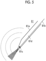
- Fig. 5 is a cross-sectional view including a central axis extending in a lengthwise direction of the puncture needle 61.
- the puncture needle 61 has an opening at a distal end formed at an acute angle, and includes a puncture needle body 61a formed in a hollow shape, an optical fiber 61b that guides light emitted from the photoacoustic wave light source unit 60 to the vicinity of the opening of the puncture needle 61, and a photoacoustic wave generation unit 61c that absorbs light emitted from the optical fiber 61b to generate a photoacoustic wave.
- the optical fiber 61b and the photoacoustic wave generation unit 61c are arranged in a hollow portion 61d of the puncture needle body 61a.
- the optical fiber 61b is connected to the optical fiber in the optical cable 62, for example, through an optical connector provided at a base end portion of the puncture needle 61.
- the photoacoustic wave generation unit 61c is provided on a light emission side of the optical fiber 61b, and is provided in the vicinity of the distal end of the puncture needle 61 and in an inner wall of the puncture needle body 61a.
- the photoacoustic wave generation unit 61c absorbs light emitted from the optical fiber 61b to generate a photoacoustic wave.
- the photoacoustic wave generation unit 61c is formed of, for example, epoxy resin mixed with a black pigment, polyurethane resin, fluororesin, silicon rubber, or the like. In Fig.
- the photoacoustic wave generation unit 61c is drawn to be greater than the optical fiber 61b, the invention is not limited thereto, and the photoacoustic wave generation unit 61c may have a size similar to the diameter of the optical fiber 61b.
- the photoacoustic wave generation unit 61c is limited to that described above, and a metal film or a film of an oxide having light absorbency with respect to the wavelength of light may be used as the photoacoustic wave generation unit.
- a metal film or a film of an oxide having light absorbency with respect to the wavelength of light may be used as the photoacoustic wave generation unit.
- a film of an oxide such as an iron oxide, a chromium oxide, or a manganese oxide, having high light absorbency with respect to the wavelength of light can be used.
- a metal film such as titanium (Ti) or platinum (Pt) having lower light absorbency but higher biocompatibility than an oxide may be used as the photoacoustic wave generation unit 61c.
- the position where the photoacoustic wave generation unit 61c is provided is not limited to the inner wall of the puncture needle body 61a.
- the metal film or the film of the oxide as the photoacoustic wave generation unit 61c may be formed on a light emission end of the optical fiber 61b, for example, at a film thickness of about 100 nm by vapor deposition or the like such that the film of the oxide covers cover the light emission end.
- at least a part of light emitted from the light emission end of the optical fiber 61b is absorbed by the metal film or the film of the oxide that covers the light emission end, and a photoacoustic wave is generated from the metal film or the film of the oxide.
- the ID detection circuit 60c comprises a memory that stores ID information (corresponding to identification information for identifying the device) of the photoacoustic wave light source unit 60, a reading circuit that reads the ID information from the memory, and the like.
- the ID detection circuit 60c outputs the ID information to the sub-controller 12 of the ultrasound diagnostic apparatus 10 when the photoacoustic wave light source unit 60 is connected to the connector 17 of the ultrasound diagnostic apparatus 10 or when the ultrasound diagnostic apparatus 10 is started after the connection of the photoacoustic wave light source unit 60.
- various kinds of known connection detection can be used.
- an optical sensor such as a photocoupler, may be provided or detection may be performed with an electrical or mechanical configuration.
- the sub-controller 12 performs photoacoustic image measurement only in a case where the photoacoustic image mode is selected in the operating unit 15 and the ID information of the photoacoustic wave light source unit 60 is received. That is, the photoacoustic wave transmission timing signal is output from the synchronization signal generation unit 12a. Even though the photoacoustic image mode is selected in the operating unit 15, in a case where ID information different from the ID information of the photoacoustic wave light source unit 60 is received, the sub-controller 12 does not output the photoacoustic wave transmission timing signal.
- the sub-controller 12 does not output the photoacoustic wave transmission timing signal. With this, it is possible to restrain failure in the electrocardiograph unit 30.
- the photoacoustic image mode is selected in the operating unit 15, and in a case where a device other than the photoacoustic wave light source unit 60 is connected to the connector 17, the sub-controller 12 outputs the effect to the main controller 11, and the main controller 11 makes the display unit 16 display a warning message or the like.
- the failure detection circuit 60d confirms whether or not there is failure in the photoacoustic wave light source unit 60 when the photoacoustic wave light source unit 60 is connected to the connector 17 of the ultrasound diagnostic apparatus 10, when the ultrasound diagnostic apparatus 10 is started after the connection of the photoacoustic wave light source unit 60, or when the photoacoustic wave light source unit 60 operates.
- detection of failure in the photoacoustic wave light source unit 60 for example, an abnormality of a current value or a voltage value of the light source unit 60a is detected.
- a detection signal is output to the main controller 11 through the sub-controller 12 of the ultrasound diagnostic apparatus 10, and the main controller 11 makes the display unit 16 displays the effect that failure is detected.
- the ID detection circuit 60c and the failure detection circuit 60d in the photoacoustic wave light source unit 60 are subjected to digital control based on the clock signal generated in the clock signal generation unit 12b of the ultrasound diagnostic apparatus 10. In this way, the clock signal generation unit 12b of the ultrasound diagnostic apparatus 10 is used, whereby there is no need to provide a clock signal generation unit in the photoacoustic wave light source unit 60, and it is possible to achieve reduction in size.
- Fig. 6 is a timing chart showing the synchronization signal that is output from the synchronization signal generation unit 12a, a transmission timing of an ultrasonic wave based on the synchronization signal, a transmission timing of a photoacoustic wave, and a reception timing of the ultrasonic wave in the photoacoustic image mode.
- a photoacoustic wave transmission timing signal is a synchronization signal (corresponding to a second synchronization signal of the invention) that is output from the synchronization signal generation unit 12a to the photoacoustic wave light source unit 60
- an ultrasonic wave reception timing signal is a synchronization signal (corresponding to a first synchronization signal of the invention) that is output from the synchronization signal generation unit 12a to the reception controller 14.
- the ultrasonic wave transmission timing signal and the ultrasonic wave reception timing signal are output at the same timing excluding when the photoacoustic wave transmission timing signal and the ultrasonic wave reception timing signal are output simultaneously, and the photoacoustic wave transmission timing signal is output between the ultrasonic wave transmission timing signals.
- the reception controller 14 starts reception of the reflected ultrasonic wave after a given delay time (for example, about 0.1 ⁇ s) from the timing at which the ultrasonic wave reception timing signal is received. Then, after the reflected ultrasonic wave is received in a given reception period, the reception controller 14 stops reception.
- the reception controller 14 outputs a detection signal of the reflected ultrasonic wave to the main controller 11 along with the timing at which the ultrasonic wave reception timing signal is received.
- the reception controller 14 starts reception of the photoacoustic wave immediately after the photoacoustic wave is transmitted from the photoacoustic wave generation unit 61c of the puncture needle 61 after the reception period of the reflected ultrasonic wave has elapsed. Then, the reception controller 14 stops reception after the photoacoustic wave is received in a given reception period.
- the reception period of the photoacoustic wave becomes half the reception period of the reflected ultrasonic wave.
- the reception controller 14 outputs a detection signal of the photoacoustic wave to the main controller 11 along with the timing at which the photoacoustic wave transmission timing signal is received.
- the image generation unit 11a of the main controller 11 generates an ultrasound image based on the input detection signal of the ultrasonic wave and generates a photoacoustic image based on the input detection signal of the photoacoustic wave.
- the main controller 11 makes the display unit 16 display the ultrasound image on the photoacoustic image in a superimposed manner.
- An interval between transmission of the ultrasonic wave and reception of the reflected ultrasonic wave, and transmission and reception of the photoacoustic wave may be set to one line interval. That is, detection of the reflected ultrasonic wave and detection of the photoacoustic wave may be performed alternately per line. In this case, since transmission and reception can be made to correspond on a one-to-one basis, it is possible to implement the configuration with inexpensive hardware.
- Detection of the reflected ultrasonic wave and detection of the photoacoustic wave may be performed alternately per frame.
- detection of the reflected ultrasonic wave and detection of the photoacoustic wave may be performed alternately per a plurality of lines.
- detection of the reflected ultrasonic wave of the first to 64th lines may be performed, and then, detection of the photoacoustic wave of the first to 64th lines may be performed.
- detection of the reflected ultrasonic wave of the 65th to 128th lines may be performed, and then, detection of the photoacoustic wave of the 65th to 128th lines may be performed.
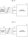
- Fig. 7 shows a state in which the electrocardiograph unit 30 is connected to the connector 17
- Fig. 8 shows a state in which the photoacoustic wave light source unit 60 is connected to the connector 17.
- the connector 17 of the embodiment has five wirings 17a to 17e as shown in Figs. 7 and 8 .
- the first wiring 17a is a power line, and electric power is supplied from the ultrasound diagnostic apparatus 10 to the electrocardiograph unit 30 or the photoacoustic wave light source unit 60 through the first wiring 17a.
- the second wiring 17b is a clock signal line, and the clock signal is supplied from the ultrasound diagnostic apparatus 10 to the electrocardiograph unit 30 or the photoacoustic wave light source unit 60 through the second wiring 17b.
- the third wiring 17c is a synchronization signal line, and the synchronization signal is transmitted from the ultrasound diagnostic apparatus 10 to the electrocardiograph unit 30 or the photoacoustic wave light source unit 60 through the third wiring 17c.
- the fourth wiring 17d is a data line, and the ECG signal, the ID information, and the failure detection signal output from the electrocardiograph unit 30 are input to the ultrasound diagnostic apparatus 10 through the fourth wiring 17d. Furthermore, the ID information and the failure detection signal output from the photoacoustic wave light source unit 60 are input to the ultrasound diagnostic apparatus 10 through the fourth wiring 17d. In Figs. 7 and 8 , although the fourth wiring 17d is shown by one line, it is preferable that the fourth wiring 17d has two or three lines to perform parallel transmission.
- the fifth wiring 17e is a ground line, and a ground potential is supplied from the ultrasound diagnostic apparatus 10 to the electrocardiograph unit 30 or the photoacoustic wave light source unit 60 through the fifth wiring 17e.
- the ultrasound diagnostic system 1 of the first embodiment described above a configuration is made in which the ultrasound probe 20 is controlled based on the synchronization signal generated by the synchronization signal generation unit 12a, the connector 17 having the synchronization signal line transmitting the synchronization signal generated by the synchronization signal generation unit 12a is provided, and the photoacoustic wave light source unit 60 is connectable to the connector 17. For this reason, it is possible to synchronize emission of light from the photoacoustic wave light source unit 60 and reception in the ultrasound probe 20 with high accuracy.
- the electrocardiograph unit 30 is connectable to the connector 17 of the ultrasound diagnostic apparatus 10
- a configuration in which a phonocardiograph unit (corresponding to a phonocardiograph of the invention) may be connectable to the connector 17 of the ultrasound diagnostic apparatus 10 may be made.
- the phonocardiograph unit is configured by providing a microphone for cardiac sound measurement instead of the electrode group 30a of the electrocardiograph unit 30.
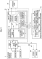
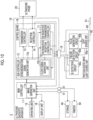
- FIGs. 9 and 10 are block diagrams showing the schematic configuration of an ultrasound diagnostic system 2 of the embodiment.
- the appearance of the ultrasound diagnostic system 2 of the embodiment is the same as the ultrasound diagnostic system 1 of the first embodiment shown in Fig. 3 .
- the ultrasound diagnostic system 2 of the second embodiment comprises a connector 19 configured such that both of a probe 70 for continuous wave Doppler measurement and the photoacoustic wave light source unit 60 are connectable.
- Fig. 9 shows a state in which the probe 70 for continuous wave Doppler measurement is connected to the connector 19 of the ultrasound diagnostic apparatus 10.
- Fig. 10 shows a state in which the photoacoustic wave light source unit 60 is connected to the connector 19.
- the ultrasound diagnostic system 2 shown in Fig. 10 is the same as the ultrasound diagnostic system 1 shown in Fig. 9 except that, instead of the probe 70 for continuous wave Doppler measurement in the ultrasound diagnostic system 2 shown in Fig. 9 , the photoacoustic wave light source unit 60 is connected to the connector 19.
- the ultrasound diagnostic apparatus 10 in the ultrasound diagnostic system 2 of the embodiment comprises a continuous wave (CW) dedicated transmission controller 71 and a CW dedicated reception controller 72 instead of the ECG processor 12c of the ultrasound diagnostic apparatus 10 of the first embodiment.
- CW continuous wave
- the CW dedicated transmission controller 71 generates a CW dedicated transmission signal based on the synchronization signal output from the synchronization signal generation unit 12a and transmits the CW dedicated transmission signal to the probe 70 for continuous wave Doppler measurement through the connector 19.
- the probe 70 for continuous wave Doppler measurement makes an ultrasonic wave of continuous waves be transmitted from the detection element 70a for transmission to the subject in response to the CW dedicated transmission signal.
- the CW dedicated reception controller 72 performs reception control of a reflected ultrasonic wave reflected from the subject with transmission of the ultrasonic wave of the continuous waves to the subject based on the synchronization signal output from the synchronization signal generation unit 12a.
- the image generation unit 11a in the main controller 11 receives a detection signal output from a detection element 70b for reception of probe 70 for continuous wave Doppler measurement and generates a CW Doppler image based on the detection signal.
- the CW dedicated transmission controller 71 and the CW dedicated reception controller 72 comprise an electric circuit that performs transmission and reception control described above, and the like.
- the sub-controller 12 controls transmission of the ultrasonic wave from the ultrasound probe 20 and reception of the reflected ultrasonic wave reflected from the subject with transmission of the ultrasonic wave to the subject. Furthermore, the sub-controller 12 controls transmission of the ultrasonic wave of the continuous waves from the probe 70 for continuous wave Doppler measurement described above and reception of the reflected ultrasonic wave reflected from the subject with transmission of the ultrasonic wave to the subject. In addition, as in the first embodiment, the sub-controller 12 controls emission of light from the photoacoustic wave light source unit 60.
- the configurations of the synchronization signal generation unit 12a and the clock signal generation unit 12b in the sub-controller 12 are the same as those in the first embodiment.
- the operating unit 15 of the embodiment receives ON and OFF operations of a continuous wave Doppler measurement mode and ON and OFF operations of the photoacoustic image mode.
- the synchronization signal generation unit 12a In a case where the ON operation of the continuous wave Doppler measurement mode is received in the operating unit 15, the synchronization signal generation unit 12a outputs a CW dedicated transmission timing signal and a CW dedicated reception timing signal described below based on a control schedule set in advance. In a case where the ON operation of the photoacoustic image mode is received in the operating unit 15, the synchronization signal generation unit 12a outputs a photoacoustic wave transmission timing signal based on a control schedule set in advance.
- the probe 70 for continuous wave Doppler measurement comprises the detection element 70a for transmission, the detection element 70b for reception, an ID detection circuit 70c, and a failure detection circuit 70d.
- the detection element 70a for transmission is configured of a piezoelectric element or the like, and transmits the ultrasonic wave of the continuous waves to the subject.
- the detection element 70b for reception is also configured of a piezoelectric element or the like, and receives the reflected ultrasonic wave reflected from the subject with transmission of the ultrasonic wave of the continuous waves.
- the ID detection circuit 70c comprises a memory that stores ID information of the probe 70 for continuous wave Doppler measurement, a reading circuit that reads the ID information from the memory, and the like.
- the ID detection circuit 70c outputs the ID information to the sub-controller 12 of the ultrasound diagnostic apparatus 10 when the probe 70 for continuous wave Doppler measurement is connected to the connector 19 of the ultrasound diagnostic apparatus 10 or when the ultrasound diagnostic apparatus 10 is started after the connection of the probe 70 for continuous wave Doppler measurement.
- the sub-controller 12 performs continuous wave Doppler measurement only in a case where the ID information of the probe 70 for continuous wave Doppler measurement is received.
- various kinds of known connection detection can be used.
- an optical sensor such as a photocoupler, may be provided or detection may be performed with a mechanical configuration.
- the sub-controller 12 performs continuous wave Doppler measurement only in a case where the continuous wave Doppler measurement mode is selected in the operating unit 15 and the ID information of the probe 70 for continuous wave Doppler measurement is received. That is, the CW dedicated transmission timing signal and the CW dedicated reception timing signal are output from the synchronization signal generation unit 12a. Even though the continuous wave Doppler measurement mode is selected in the operating unit 15, in a case where ID information different from the ID information of the probe 70 for continuous wave Doppler measurement is received, the sub-controller 12 does not output the CW dedicated transmission timing signal and the CW dedicated reception timing signal.
- the sub-controller 12 does not output the CW dedicated transmission timing signal and the CW dedicated reception timing signal. With this, it is possible to restrain failure in the photoacoustic wave light source unit 60 and erroneous emission of light from the photoacoustic wave light source unit 60.
- the sub-controller 12 In a case where the continuous wave Doppler measurement mode is selected in the operating unit 15, and in a case where a device other than the probe 70 for continuous wave Doppler measurement is connected to the connector 19, the sub-controller 12 outputs the effect to the main controller 11, and the main controller 11 makes the display unit 16 display a warning message or the like.
- the failure detection circuit 70d confirms whether or not there is failure in the probe 70 for continuous wave Doppler measurement when the probe 70 for continuous wave Doppler measurement is connected to the connector 19 of the ultrasound diagnostic apparatus 10, when the ultrasound diagnostic apparatus 10 is started after the connection of the probe 70 for continuous wave Doppler measurement, or when the probe 70 for continuous wave Doppler measurement operates.
- detection of failure in the probe 70 for continuous wave Doppler measurement for example, detection of short-circuit or open circuit of the wirings of the detection element 70a for transmission and the detection element 70b for reception, or the like is exemplified.
- a detection signal is output to the main controller 11 through the sub-controller 12 of the ultrasound diagnostic apparatus 10, and the main controller 11 makes the display unit 16 display the effect that failure is detected.
- the ID detection circuit 70c and the failure detection circuit 70d in the probe 70 for continuous wave Doppler measurement are subjected to digital control based on the clock signal generated in the clock signal generation unit 12b of the ultrasound diagnostic apparatus 10. In this way, the clock signal generation unit 12b of the ultrasound diagnostic apparatus 10 is used, whereby there is no need to provide a clock signal generation unit in the probe 70 for continuous wave Doppler measurement, and it is possible to achieve reduction in size.
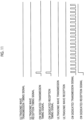
- Fig. 11 is a timing chart showing the synchronization signal that is output from the synchronization signal generation unit 12a, a transmission timing of the ultrasonic wave of the continuous waves based on the synchronization signal, and the reception timing of the ultrasonic wave. Measurement of the ultrasound image in the ultrasound probe 20 and continuous wave Doppler measurement in the probe 70 for continuous wave Doppler measurement are not simultaneously performed, and only one of measurement of the ultrasound image and continuous wave Doppler measurement is performed. For this reason, in Fig. 11 , the ultrasonic wave transmission timing signal and the ultrasonic wave reception timing signal remain zero.
- the CW dedicated transmission timing signal shown in Fig. 11 is a synchronization signal (corresponding to a second synchronization signal of the invention) that is output from the synchronization signal generation unit 12a to the CW dedicated transmission controller 71
- the CW dedicated reception timing signal is a synchronization signal (corresponding to a second synchronization signal of the invention) that is output from the synchronization signal generation unit 12a to the CW dedicated reception controller 72
- the CW dedicated transmission signal is a control signal (corresponding to a signal generated based on a second synchronization signal of the invention) that is output from the CW dedicated transmission controller 71 to the detection element 70a for transmission
- a CW dedicated reception signal is a control signal (corresponding to a signal generated based on a second synchronization signal of the invention) that is output from the CW dedicated reception controller 72 to the detection element 70b for reception.
- the CW dedicated transmission timing signal and the CW dedicated reception timing signal are output at the same timing.
- the CW dedicated transmission controller 71 outputs the CW dedicated transmission signal having continuous pulse waves to the detection element 70a for transmission in response to the input CW dedicated transmission timing signal.
- the detection element 70a for transmission transmits the ultrasonic wave of the continuous waves to the subject in response to the input CW dedicated transmission signal.
- the CW dedicated reception controller 72 outputs the CW dedicated reception signal to the detection element 70b for reception in response to the input CW dedicated reception timing signal.
- the detection element 70b for reception continuously performs reception of the ultrasonic wave in response to the CW dedicated reception signal.
- a detection signal detected by the detection element 70b for reception is received by the CW dedicated reception controller 72 and is then output to the main controller 11. Then, in the image generation unit 11a of the main controller 11, a continuous wave Doppler measurement image is generated based on the input detection signal and is displayed on the display unit 16.
- control signal (corresponding to a signal generated based on a second synchronization signal of the invention) is output from the CW dedicated transmission controller 71 to the pulse generation circuit 60b in response to the synchronization signal output from the synchronization signal generation unit 12a, and the pulse generation circuit 60b generates a pulse signal based on the input control signal.
- the light source unit 60a emits pulsed light in response to the pulse signal output from the pulse generation circuit 60b.
- the CW dedicated transmission controller 71 outputs the control signal using monopolar transmission.
- the ON and OFF operations of the photoacoustic image mode are received by the operating unit 15.
- the synchronization signal generation unit 12a outputs the synchronization signal based on a control schedule set in advance.
- the synchronization signal that is output from the synchronization signal generation unit 12a, the transmission timing of the ultrasonic wave based on the synchronization signal, the transmission timing of the photoacoustic wave, and the reception timing of the ultrasonic wave are the same as those in the timing chart shown in Fig. 6 .
- the operation of the ID detection circuit 70c and the failure detection circuit 70d in the photoacoustic wave light source unit 60 is the same as that in the above-described embodiment.
- Fig. 12 shows a state in which the probe 70 for continuous wave Doppler measurement is connected to the connector 19
- Fig. 13 shows a state in which the photoacoustic wave light source unit 60 is connected to the connector 19.
- the connector 19 of the embodiment has five wirings 19a to 19e as shown in Figs. 12 and 13 .
- the first wiring 19a is a synchronization signal line (also referred to as a transmission signal line), and in the continuous wave Doppler measurement mode, the CW dedicated transmission signal is transmitted from the ultrasound diagnostic apparatus 10 to the detection element 70a for transmission through the first wiring 19a. In the photoacoustic image mode, the photoacoustic wave transmission timing signal is transmitted from the ultrasound diagnostic apparatus 10 to the pulse generation circuit 60b through the first wiring 19a.
- the second wiring 19b is a clock signal line, and the clock signal is supplied from the ultrasound diagnostic apparatus 10 to the probe 70 for continuous wave Doppler measurement or the photoacoustic wave light source unit 60 through the second wiring 19b.
- the third wiring 19c is a data line, and the ID information and the failure detection signal output from the probe 70 for continuous wave Doppler measurement are input to the ultrasound diagnostic apparatus 10 through the third wiring 19c. Furthermore, the ID information and the failure detection signal output from the photoacoustic wave light source unit 60 are input to the ultrasound diagnostic apparatus 10 through the third wiring 19c.
- the third wiring 19c is shown by one line, it is preferable that the third wiring 19c has two lines to perform parallel transmission.
- the fourth wiring 19d is a ground line, and a ground potential is supplied from the ultrasound diagnostic apparatus 10 to the probe 70 for continuous wave Doppler measurement or the photoacoustic wave light source unit 60 through the fourth wiring 19d.
- the fifth wiring 19e is a detection signal line (also referred to as a reception signal line), and the detection signal (also referred to as a reception signal) detected by the detection element 70b for reception of the probe 70 for continuous wave Doppler measurement is output to the CW dedicated reception controller 72 through the fifth wiring 19e.
- the ultrasound diagnostic system 2 of the second embodiment described above a configuration is made in which the ultrasound probe 20 is controlled based on the synchronization signal generated by the synchronization signal generation unit 12a, the connector 19 having the synchronization signal line transmitting the synchronization signal generated by the synchronization signal generation unit 12a is provided, and both of the probe 70 for continuous wave Doppler measurement and the photoacoustic wave light source unit 60 are connectable to the connector 19. Accordingly, it is possible to reduce the space of the connector, and to achieve reduction in size. In addition, it is possible to restrain deterioration of electrical safety and EMC performance due to an increase in the number of connectors.
- the probe 70 for continuous wave Doppler measurement is a device for circulatory diagnosis, and is not used simultaneously with the photoacoustic image (puncture) clinically. Accordingly, there are no problems in particular even though the probe 70 for continuous wave Doppler measurement and the photoacoustic wave light source unit 60 are connected to the connector 19 exclusively.
- the photoacoustic wave light source unit 60, the electrocardiograph unit 30, and the probe 70 for continuous wave Doppler measurement are connectable to one connector.
- the connector 17 of the first embodiment or the connector 19 of the second embodiment may be a connector dedicated to the photoacoustic wave light source unit 60.
- the photoacoustic wave is transmitted once at one ultrasonic wave reception interval (between the ultrasonic wave reception timing signals) as shown in Fig. 6
- the invention is not limited thereto, and as shown in Fig. 14 , a delay interval ⁇ T may be provided and the photoacoustic wave may be transmitted multiple times.
- the ultrasonic wave reception interval may be an interval during which a signal of one line is detected by the ultrasound probe 20 or may be an interval during which a signal of one frame is detected by the ultrasound probe 20.
- FIG. 16 is a schematic view in which the above-described processing is arranged in time series. In Fig. 16 , the processing progresses from left to right. A portion a of Fig.
- FIG. 17 shows a photoacoustic image detected with transmission of an initial photoacoustic wave
- a portion b of Fig. 17 shows a photoacoustic image detected with transmission of a second photoacoustic wave
- a portion c of Fig. 17 shows a photoacoustic image time-advanced by ⁇ T.
- a portion d of Fig. 17 shows a photoacoustic image after the above-described threshold value processing is executed. With this, it is possible to more clearly display the distal end position of the puncture needle 61.
- the photoacoustic image with transmission of the initial photoacoustic wave indicates the real distal end of the puncture needle 61.
- the invention is not limited to the flow of the processing shown in Fig. 16 , and correlation filtering processing may be executed to generate the same photoacoustic image as the photoacoustic image that is generated through the processing shown in Fig. 16 .
- the ultrasound diagnostic apparatus 10 is portable, the invention is not limited to a portable ultrasound diagnostic apparatus, and may also be applied to a stationary ultrasound diagnostic apparatus.
- the insertion object may be a needle for radiofrequency ablation that houses an electrode for use in radiofrequency ablation, a catheter that is inserted into a blood vessel, or a guide wire of the catheter that is inserted into the blood vessel.
- an optical fiber for laser treatment may be applied.
- the insertion object and the photoacoustic measurement device of the invention are not limited only to the above-described embodiments, and various corrections and alterations in the configurations of the above-described embodiments are also included in the scope of the invention, as far as they fall within the scope of the appended claims.
Landscapes
- Health & Medical Sciences (AREA)
- Life Sciences & Earth Sciences (AREA)
- Engineering & Computer Science (AREA)
- Physics & Mathematics (AREA)
- Medical Informatics (AREA)
- Animal Behavior & Ethology (AREA)
- Veterinary Medicine (AREA)
- Public Health (AREA)
- Biomedical Technology (AREA)
- Heart & Thoracic Surgery (AREA)
- Biophysics (AREA)
- Molecular Biology (AREA)
- Surgery (AREA)
- Pathology (AREA)
- General Health & Medical Sciences (AREA)
- Nuclear Medicine, Radiotherapy & Molecular Imaging (AREA)
- Radiology & Medical Imaging (AREA)
- Computer Vision & Pattern Recognition (AREA)
- Acoustics & Sound (AREA)
- Human Computer Interaction (AREA)
- Ultra Sonic Daignosis Equipment (AREA)
Claims (10)
- Ultraschalldiagnosevorrichtung (10), umfassend:eine Steuerung (12), die eine Synchronisationssignal-Erzeugungseinheit (12a) aufweist, die ein erstes Synchronisationssignal zum Steuern des Sendens und des Empfangens einer Ultraschallwelle in einer Ultraschallsonde (20) erzeugt, und konfiguriert ist zum Steuern der Ultraschallsonde basierend auf dem ersten Synchronisationssignal;eine Ultraschallbild-Erzeugungseinheit (11a), konfiguriert zum Erzeugen eines Ultraschallbilds basierend auf einem von der Ultraschallsonde (20) erfassten Signal; undeinen Verbinder (17), der eine Synchronisationssignal-Leitung (17a), eine Datenleitung (17d), eine Stromversorgungsleitung (17a), eine Taktsignalleitung (17b), eine Masseleitung (17e) aufweist, wobei der Verbinder konfiguriert ist zum Ausgeben elektrischer Leistung nach außen über die Stromversorgungsleitung, des Taktsignals nach außen über die Taktsignalleitung, Massepotential nach außen über die Masseleitung, eines zweiten Synchronisationssignals oder eines Signals, welches basierend auf dem zweiten Synchronisationssignal erzeugt wird, nach außen über die Synchronisationssignal-Leitung (17a), wobei das zweite Synchronisationssignal erzeugt wird in der Synchronisationssignal-Erzeugungseinheit, wobei weiterhin die Synchronisationssignal-Leitung (17a) konfiguriert ist zum Senden des zweiten Synchronisationssignals oder des basierend auf dem zweiten Synchronisationssignal erzeugten Signals, und die Datenleitung (17d) unabhängig ist von der Synchronisationssignal-Leitung (17a), wobei die Datenleitung konfiguriert ist zum Eingeben von Daten in die Ultraschalldiagnosevorrichtung,wobei der Verbinder (17) derart konfiguriert ist, dass eine Lichtquelleneinrichtung (60) anschließbar ist, welche Licht emittiert, welches auf ein Einführobjekt (61) auftrifft, das eine Photoakustikwellen-Erzeugungseinheit (61c) besitzt, welches das Licht absorbiert und eine Photoakustikwelle erzeugt.
- Ultraschalldiagnosevorrichtung nach Anspruch 1, bei der das zweite Synchronisationssignal derart aufgebaut ist, dass die Lichtquelleneinrichtung (60) das Licht basierend auf dem zweiten Synchronisationssignal emittiert, wenn die Lichtquelleneinrichtung an den Verbinder angeschlossen ist.
- Ultraschalldiagnosevorrichtung nach Anspruch 1 oder 2, bei der der Verbinder (17) derart konfiguriert ist, dass eine andere, von der Lichtquelleneinrichtung (60) verschiedene Einrichtung ebenfalls anschließbar ist.
- Ultraschalldiagnosevorrichtung nach Anspruch 3,
bei der die Identifikationsinformation zum Identifizieren der anderen Einrichtung in der anderen Einrichtung gespeichert ist, und die Steuerung (12) konfiguriert ist zum Erfassen der Identifikationsinformation über den Verbinder (17) und zum Steuern der Abgabe des zweiten Synchronisationssignals nach Maßgabe der erfassten Identifikationsinformation. - Ultraschalldiagnosevorrichtung nach Anspruch 3 oder 4, bei der der Verbinder (17) derart konfiguriert ist, dass ein Elektrokardiograph oder ein Phonokardiograph anschließbar ist.
- Ultraschalldiagnosevorrichtung nach einem der Ansprüche 1 bis 5,bei der die Synchronisationssignal-Erzeugungseinheit (12a) eine Taktsignal-Erzeugungseinheit zum Erzeugen eines Taktsignals besitzt, undder Verbinder (17) konfiguriert ist zum Ausgeben des Taktsignals nach außen über die Taktsignalleitung.
- Ultraschalldiagnosevorrichtung nach Anspruch 6,
bei der ein Prozessor (11), der die Ultraschallbild-Erzeugungseinheit bildet, konfiguriert ist zum Arbeiten basierend auf einem von dem Taktsignal verschiedenen Taktsignal. - Ultraschalldiagnosevorrichtung nach einem der Ansprüche 1 bis 7, bei der die Synchronisationssignal-Erzeugungseinheit (12a) konfiguriert ist zum Erzeugen des ersten Synchronisationssignals und des zweiten Synchronisationssignals derart, dass die Lichtquelleneinrichtung, wenn sie an den Verbinder (60) angeschlossen ist, das Licht mehrmals emittiert, wenn ein Signal auf einer Leitung von der Ultraschallsonde (70) nachgewiesen wird.
- Ultraschalldiagnosevorrichtung nach einem der Ansprüche 1 bis 7,
bei der die Synchronisationssignal-Erzeugungseinheit (12a) konfiguriert ist zum Erzeugen des ersten Synchronisationssignals und des zweiten Synchronisationssignals derart, dass die Lichtquelle, wenn sie an den Verbinder angeschlossen ist, das Licht mehrmals emittiert, während ein Signal eines Vollbilds durch die Ultraschallsonde nachgewiesen wird. - Ultraschalldiagnosevorrichtung nach einem der Ansprüche 1 bis 9, die als tragbare Ultraschalldiagnosevorrichtung (10) ausgebildet ist.
Applications Claiming Priority (2)
| Application Number | Priority Date | Filing Date | Title |
|---|---|---|---|
| JP2017065095 | 2017-03-29 | ||
| PCT/JP2018/005394 WO2018179966A1 (ja) | 2017-03-29 | 2018-02-16 | 超音波診断装置 |
Publications (3)
| Publication Number | Publication Date |
|---|---|
| EP3603530A1 EP3603530A1 (de) | 2020-02-05 |
| EP3603530A4 EP3603530A4 (de) | 2020-04-15 |
| EP3603530B1 true EP3603530B1 (de) | 2023-03-01 |
Family
ID=63675041
Family Applications (1)
| Application Number | Title | Priority Date | Filing Date |
|---|---|---|---|
| EP18777665.3A Active EP3603530B1 (de) | 2017-03-29 | 2018-02-16 | Ultraschalldiagnosevorrichtung |
Country Status (5)
| Country | Link |
|---|---|
| US (1) | US12611175B2 (de) |
| EP (1) | EP3603530B1 (de) |
| JP (1) | JP6739626B2 (de) |
| CN (2) | CN116392163B (de) |
| WO (1) | WO2018179966A1 (de) |
Families Citing this family (4)
| Publication number | Priority date | Publication date | Assignee | Title |
|---|---|---|---|---|
| JP7168474B2 (ja) * | 2019-01-31 | 2022-11-09 | 富士フイルムヘルスケア株式会社 | 超音波撮像装置、治療支援システム、及び、画像処理方法 |
| CA3215539A1 (en) | 2021-04-15 | 2022-10-20 | Laura Kvarnstrand | Interactive augmented reality sewing machines |
| JP2024006649A (ja) * | 2022-07-04 | 2024-01-17 | 富士フイルムヘルスケア株式会社 | 超音波撮像装置 |
| CN115462766B (zh) * | 2022-10-09 | 2023-06-13 | 深圳英美达医疗技术有限公司 | 信号同步采集方法、系统及可读存储介质 |
Family Cites Families (21)
| Publication number | Priority date | Publication date | Assignee | Title |
|---|---|---|---|---|
| US5957846A (en) * | 1995-06-29 | 1999-09-28 | Teratech Corporation | Portable ultrasound imaging system |
| US7927278B2 (en) * | 2002-12-13 | 2011-04-19 | California Institute Of Technology | Split-screen display system and standardized methods for ultrasound image acquisition and multi-frame data processing |
| US7068867B2 (en) * | 2003-01-02 | 2006-06-27 | Glucon Medical Ltd | Ultrasonic position indicator |
| WO2006118499A1 (en) * | 2005-05-04 | 2006-11-09 | St. Jude Medical Ab | Synchronization of implantable medical devices |
| CN103079450B (zh) * | 2011-03-29 | 2015-05-13 | 奥林巴斯医疗株式会社 | 内窥镜用适配器、内窥镜用处理器和内窥镜系统 |
| JP2014039801A (ja) * | 2012-07-27 | 2014-03-06 | Fujifilm Corp | 音響信号検出用のプローブおよびそれを備えた光音響計測装置 |
| JP6112861B2 (ja) * | 2012-12-28 | 2017-04-12 | キヤノン株式会社 | 被検体情報取得装置、信号処理装置および表示装置 |
| JP6066233B2 (ja) | 2013-01-09 | 2017-01-25 | 富士フイルム株式会社 | 光音響画像生成装置 |
| JP5819387B2 (ja) * | 2013-01-09 | 2015-11-24 | 富士フイルム株式会社 | 光音響画像生成装置及び挿入物 |
| DE102013211627A1 (de) | 2013-06-20 | 2014-12-24 | Robert Bosch Gmbh | Elektroakustischer Wandler |
| JP2015029550A (ja) * | 2013-07-31 | 2015-02-16 | 船井電機株式会社 | 光音響画像化装置 |
| JP6041832B2 (ja) * | 2013-08-02 | 2016-12-14 | 富士フイルム株式会社 | 光音響画像生成装置及びその作動方法 |
| JP6388360B2 (ja) * | 2013-12-27 | 2018-09-12 | キヤノン株式会社 | 被検体情報取得装置および被検体情報取得装置の制御方法 |
| WO2016000061A1 (en) | 2014-07-02 | 2016-01-07 | University Health Network | Acoustic neck fluid volume assessment system and method |
| JP6215470B2 (ja) * | 2014-07-08 | 2017-10-18 | 富士フイルム株式会社 | 光音響画像生成装置及び挿入物 |
| JP6250510B2 (ja) * | 2014-09-25 | 2017-12-20 | 富士フイルム株式会社 | 光音響画像生成装置 |
| KR102445161B1 (ko) * | 2015-01-20 | 2022-09-21 | 삼성메디슨 주식회사 | 프로브, 초음파 영상 장치 및 초음파 영상 장치의 제어 방법 |
| CN107529989B (zh) * | 2015-04-14 | 2023-08-04 | 皇家飞利浦有限公司 | 血管内装置、系统和形成方法 |
| WO2017002338A1 (ja) | 2015-06-30 | 2017-01-05 | 富士フイルム株式会社 | 光音響画像生成装置及び挿入物 |
| US10660604B2 (en) * | 2015-07-13 | 2020-05-26 | Otonexus Medical Technologies, Inc. | Apparatus and method for characterization of acute otitis media |
| KR101952921B1 (ko) * | 2016-09-19 | 2019-02-28 | 포항공과대학교 산학협력단 | 초음파와 광음향 신호 검출용 카테터 및 이를 이용한 초음파 영상과 광음향 영상 획득 시스템 |
-
2018
- 2018-02-16 CN CN202310383146.8A patent/CN116392163B/zh active Active
- 2018-02-16 WO PCT/JP2018/005394 patent/WO2018179966A1/ja not_active Ceased
- 2018-02-16 CN CN201880021555.0A patent/CN110475516B/zh active Active
- 2018-02-16 JP JP2019508741A patent/JP6739626B2/ja active Active
- 2018-02-16 EP EP18777665.3A patent/EP3603530B1/de active Active
-
2019
- 2019-09-16 US US16/572,020 patent/US12611175B2/en active Active
Also Published As
| Publication number | Publication date |
|---|---|
| CN116392163A (zh) | 2023-07-07 |
| WO2018179966A1 (ja) | 2018-10-04 |
| US20200008782A1 (en) | 2020-01-09 |
| CN110475516B (zh) | 2023-07-14 |
| US12611175B2 (en) | 2026-04-28 |
| CN110475516A (zh) | 2019-11-19 |
| JP6739626B2 (ja) | 2020-08-12 |
| EP3603530A4 (de) | 2020-04-15 |
| CN116392163B (zh) | 2026-02-13 |
| JPWO2018179966A1 (ja) | 2020-02-06 |
| EP3603530A1 (de) | 2020-02-05 |
Similar Documents
| Publication | Publication Date | Title |
|---|---|---|
| US12611175B2 (en) | Ultrasound diagnostic apparatus | |
| US5383460A (en) | Method and apparatus for ultrasound imaging and atherectomy | |
| US7068867B2 (en) | Ultrasonic position indicator | |
| US6086534A (en) | Apparatus and method of myocardial revascularization using ultrasonic pulse-echo distance ranging | |
| JP5443732B2 (ja) | 超音波探触子、及びその超音波探触子を用いた超音波診断装置 | |
| EP2679161A1 (de) | Akustooptische bilderzeugungsvorrichtung und verfahren dafür | |
| US11759167B2 (en) | Method and apparatus for visualizing a medical instrument under ultrasound guidance | |
| EP3167812B1 (de) | Vorrichtung und einsatz zur erzeugung photoakustischer bilder | |
| WO2018056187A1 (ja) | 光音響画像生成装置 | |
| JP7112713B2 (ja) | 心拍計測処理装置 | |
| US20060173337A1 (en) | Intravascular ultrasound probing device | |
| JP2013255545A (ja) | 超音波診断装置および超音波診断装置の制御方法 | |
| JP5331431B2 (ja) | 超音波診断装置 | |
| US20200229789A1 (en) | Ultrasound diagnostic apparatus and method for controlling ultrasound diagnostic apparatus | |
| JP2005066310A (ja) | 静脈注射装置 | |
| CN113520454A (zh) | 一种超声瞬时弹性检测设备、探头以及方法 | |
| US12616377B2 (en) | Transponder tracking and ultrasound image enhancement | |
| US20240423482A1 (en) | Transponder tracking and ultrasound image enhancement | |
| JP4557261B2 (ja) | 超音波治療装置 | |
| JP6745888B2 (ja) | 光音響計測装置 | |
| JPH08131438A (ja) | 超音波ドプラ診断装置 | |
| WO2024263947A1 (en) | Transponder tracking and ultrasound image enhancement | |
| JP6685413B2 (ja) | 光音響計測装置 | |
| JP2016209018A (ja) | 画像処理装置および方法、プログラム | |
| JPWO2019150770A1 (ja) | 音響波装置および音響波装置の制御方法 |
Legal Events
| Date | Code | Title | Description |
|---|---|---|---|
| STAA | Information on the status of an ep patent application or granted ep patent |
Free format text: STATUS: THE INTERNATIONAL PUBLICATION HAS BEEN MADE |
|
| PUAI | Public reference made under article 153(3) epc to a published international application that has entered the european phase |
Free format text: ORIGINAL CODE: 0009012 |
|
| STAA | Information on the status of an ep patent application or granted ep patent |
Free format text: STATUS: REQUEST FOR EXAMINATION WAS MADE |
|
| 17P | Request for examination filed |
Effective date: 20190911 |
|
| AK | Designated contracting states |
Kind code of ref document: A1 Designated state(s): AL AT BE BG CH CY CZ DE DK EE ES FI FR GB GR HR HU IE IS IT LI LT LU LV MC MK MT NL NO PL PT RO RS SE SI SK SM TR |
|
| AX | Request for extension of the european patent |
Extension state: BA ME |
|
| A4 | Supplementary search report drawn up and despatched |
Effective date: 20200316 |
|
| RIC1 | Information provided on ipc code assigned before grant |
Ipc: A61B 8/13 20060101AFI20200310BHEP Ipc: A61B 8/00 20060101ALI20200310BHEP Ipc: A61B 8/08 20060101ALI20200310BHEP Ipc: A61B 8/14 20060101ALI20200310BHEP |
|
| DAV | Request for validation of the european patent (deleted) | ||
| DAX | Request for extension of the european patent (deleted) | ||
| RAP3 | Party data changed (applicant data changed or rights of an application transferred) |
Owner name: FUJIFILM CORPORATION |
|
| GRAP | Despatch of communication of intention to grant a patent |
Free format text: ORIGINAL CODE: EPIDOSNIGR1 |
|
| STAA | Information on the status of an ep patent application or granted ep patent |
Free format text: STATUS: GRANT OF PATENT IS INTENDED |
|
| INTG | Intention to grant announced |
Effective date: 20220916 |
|
| GRAS | Grant fee paid |
Free format text: ORIGINAL CODE: EPIDOSNIGR3 |
|
| GRAA | (expected) grant |
Free format text: ORIGINAL CODE: 0009210 |
|
| STAA | Information on the status of an ep patent application or granted ep patent |
Free format text: STATUS: THE PATENT HAS BEEN GRANTED |
|
| AK | Designated contracting states |
Kind code of ref document: B1 Designated state(s): AL AT BE BG CH CY CZ DE DK EE ES FI FR GB GR HR HU IE IS IT LI LT LU LV MC MK MT NL NO PL PT RO RS SE SI SK SM TR |
|
| REG | Reference to a national code |
Ref country code: GB Ref legal event code: FG4D |
|
| REG | Reference to a national code |
Ref country code: CH Ref legal event code: EP Ref country code: AT Ref legal event code: REF Ref document number: 1550465 Country of ref document: AT Kind code of ref document: T Effective date: 20230315 |
|
| REG | Reference to a national code |
Ref country code: DE Ref legal event code: R096 Ref document number: 602018046702 Country of ref document: DE |
|
| REG | Reference to a national code |
Ref country code: IE Ref legal event code: FG4D |
|
| P01 | Opt-out of the competence of the unified patent court (upc) registered |
Effective date: 20230515 |
|
| REG | Reference to a national code |
Ref country code: LT Ref legal event code: MG9D |
|
| REG | Reference to a national code |
Ref country code: NL Ref legal event code: MP Effective date: 20230301 |
|
| PG25 | Lapsed in a contracting state [announced via postgrant information from national office to epo] |
Ref country code: RS Free format text: LAPSE BECAUSE OF FAILURE TO SUBMIT A TRANSLATION OF THE DESCRIPTION OR TO PAY THE FEE WITHIN THE PRESCRIBED TIME-LIMIT Effective date: 20230301 Ref country code: NO Free format text: LAPSE BECAUSE OF FAILURE TO SUBMIT A TRANSLATION OF THE DESCRIPTION OR TO PAY THE FEE WITHIN THE PRESCRIBED TIME-LIMIT Effective date: 20230601 Ref country code: LV Free format text: LAPSE BECAUSE OF FAILURE TO SUBMIT A TRANSLATION OF THE DESCRIPTION OR TO PAY THE FEE WITHIN THE PRESCRIBED TIME-LIMIT Effective date: 20230301 Ref country code: LT Free format text: LAPSE BECAUSE OF FAILURE TO SUBMIT A TRANSLATION OF THE DESCRIPTION OR TO PAY THE FEE WITHIN THE PRESCRIBED TIME-LIMIT Effective date: 20230301 Ref country code: HR Free format text: LAPSE BECAUSE OF FAILURE TO SUBMIT A TRANSLATION OF THE DESCRIPTION OR TO PAY THE FEE WITHIN THE PRESCRIBED TIME-LIMIT Effective date: 20230301 Ref country code: ES Free format text: LAPSE BECAUSE OF FAILURE TO SUBMIT A TRANSLATION OF THE DESCRIPTION OR TO PAY THE FEE WITHIN THE PRESCRIBED TIME-LIMIT Effective date: 20230301 |
|
| REG | Reference to a national code |
Ref country code: AT Ref legal event code: MK05 Ref document number: 1550465 Country of ref document: AT Kind code of ref document: T Effective date: 20230301 |
|
| PG25 | Lapsed in a contracting state [announced via postgrant information from national office to epo] |
Ref country code: SE Free format text: LAPSE BECAUSE OF FAILURE TO SUBMIT A TRANSLATION OF THE DESCRIPTION OR TO PAY THE FEE WITHIN THE PRESCRIBED TIME-LIMIT Effective date: 20230301 Ref country code: PL Free format text: LAPSE BECAUSE OF FAILURE TO SUBMIT A TRANSLATION OF THE DESCRIPTION OR TO PAY THE FEE WITHIN THE PRESCRIBED TIME-LIMIT Effective date: 20230301 Ref country code: NL Free format text: LAPSE BECAUSE OF FAILURE TO SUBMIT A TRANSLATION OF THE DESCRIPTION OR TO PAY THE FEE WITHIN THE PRESCRIBED TIME-LIMIT Effective date: 20230301 Ref country code: GR Free format text: LAPSE BECAUSE OF FAILURE TO SUBMIT A TRANSLATION OF THE DESCRIPTION OR TO PAY THE FEE WITHIN THE PRESCRIBED TIME-LIMIT Effective date: 20230602 Ref country code: FI Free format text: LAPSE BECAUSE OF FAILURE TO SUBMIT A TRANSLATION OF THE DESCRIPTION OR TO PAY THE FEE WITHIN THE PRESCRIBED TIME-LIMIT Effective date: 20230301 |
|
| PG25 | Lapsed in a contracting state [announced via postgrant information from national office to epo] |
Ref country code: SM Free format text: LAPSE BECAUSE OF FAILURE TO SUBMIT A TRANSLATION OF THE DESCRIPTION OR TO PAY THE FEE WITHIN THE PRESCRIBED TIME-LIMIT Effective date: 20230301 Ref country code: RO Free format text: LAPSE BECAUSE OF FAILURE TO SUBMIT A TRANSLATION OF THE DESCRIPTION OR TO PAY THE FEE WITHIN THE PRESCRIBED TIME-LIMIT Effective date: 20230301 Ref country code: PT Free format text: LAPSE BECAUSE OF FAILURE TO SUBMIT A TRANSLATION OF THE DESCRIPTION OR TO PAY THE FEE WITHIN THE PRESCRIBED TIME-LIMIT Effective date: 20230703 Ref country code: EE Free format text: LAPSE BECAUSE OF FAILURE TO SUBMIT A TRANSLATION OF THE DESCRIPTION OR TO PAY THE FEE WITHIN THE PRESCRIBED TIME-LIMIT Effective date: 20230301 Ref country code: CZ Free format text: LAPSE BECAUSE OF FAILURE TO SUBMIT A TRANSLATION OF THE DESCRIPTION OR TO PAY THE FEE WITHIN THE PRESCRIBED TIME-LIMIT Effective date: 20230301 Ref country code: AT Free format text: LAPSE BECAUSE OF FAILURE TO SUBMIT A TRANSLATION OF THE DESCRIPTION OR TO PAY THE FEE WITHIN THE PRESCRIBED TIME-LIMIT Effective date: 20230301 |
|
| PG25 | Lapsed in a contracting state [announced via postgrant information from national office to epo] |
Ref country code: SK Free format text: LAPSE BECAUSE OF FAILURE TO SUBMIT A TRANSLATION OF THE DESCRIPTION OR TO PAY THE FEE WITHIN THE PRESCRIBED TIME-LIMIT Effective date: 20230301 Ref country code: IS Free format text: LAPSE BECAUSE OF FAILURE TO SUBMIT A TRANSLATION OF THE DESCRIPTION OR TO PAY THE FEE WITHIN THE PRESCRIBED TIME-LIMIT Effective date: 20230701 |
|
| REG | Reference to a national code |
Ref country code: DE Ref legal event code: R097 Ref document number: 602018046702 Country of ref document: DE |
|
| PLBE | No opposition filed within time limit |
Free format text: ORIGINAL CODE: 0009261 |
|
| STAA | Information on the status of an ep patent application or granted ep patent |
Free format text: STATUS: NO OPPOSITION FILED WITHIN TIME LIMIT |
|
| PG25 | Lapsed in a contracting state [announced via postgrant information from national office to epo] |
Ref country code: SI Free format text: LAPSE BECAUSE OF FAILURE TO SUBMIT A TRANSLATION OF THE DESCRIPTION OR TO PAY THE FEE WITHIN THE PRESCRIBED TIME-LIMIT Effective date: 20230301 Ref country code: DK Free format text: LAPSE BECAUSE OF FAILURE TO SUBMIT A TRANSLATION OF THE DESCRIPTION OR TO PAY THE FEE WITHIN THE PRESCRIBED TIME-LIMIT Effective date: 20230301 |
|
| 26N | No opposition filed |
Effective date: 20231204 |
|
| PG25 | Lapsed in a contracting state [announced via postgrant information from national office to epo] |
Ref country code: MC Free format text: LAPSE BECAUSE OF FAILURE TO SUBMIT A TRANSLATION OF THE DESCRIPTION OR TO PAY THE FEE WITHIN THE PRESCRIBED TIME-LIMIT Effective date: 20230301 |
|
| REG | Reference to a national code |
Ref country code: CH Ref legal event code: PL |
|
| PG25 | Lapsed in a contracting state [announced via postgrant information from national office to epo] |
Ref country code: LU Free format text: LAPSE BECAUSE OF NON-PAYMENT OF DUE FEES Effective date: 20240216 |
|
| PG25 | Lapsed in a contracting state [announced via postgrant information from national office to epo] |
Ref country code: CH Free format text: LAPSE BECAUSE OF NON-PAYMENT OF DUE FEES Effective date: 20240229 |
|
| PG25 | Lapsed in a contracting state [announced via postgrant information from national office to epo] |
Ref country code: LU Free format text: LAPSE BECAUSE OF NON-PAYMENT OF DUE FEES Effective date: 20240216 Ref country code: CH Free format text: LAPSE BECAUSE OF NON-PAYMENT OF DUE FEES Effective date: 20240229 |
|
| PG25 | Lapsed in a contracting state [announced via postgrant information from national office to epo] |
Ref country code: BG Free format text: LAPSE BECAUSE OF FAILURE TO SUBMIT A TRANSLATION OF THE DESCRIPTION OR TO PAY THE FEE WITHIN THE PRESCRIBED TIME-LIMIT Effective date: 20230301 |
|
| PG25 | Lapsed in a contracting state [announced via postgrant information from national office to epo] |
Ref country code: BG Free format text: LAPSE BECAUSE OF FAILURE TO SUBMIT A TRANSLATION OF THE DESCRIPTION OR TO PAY THE FEE WITHIN THE PRESCRIBED TIME-LIMIT Effective date: 20230301 |
|
| REG | Reference to a national code |
Ref country code: BE Ref legal event code: MM Effective date: 20240229 |
|
| PG25 | Lapsed in a contracting state [announced via postgrant information from national office to epo] |
Ref country code: BE Free format text: LAPSE BECAUSE OF NON-PAYMENT OF DUE FEES Effective date: 20240229 |
|
| PG25 | Lapsed in a contracting state [announced via postgrant information from national office to epo] |
Ref country code: IE Free format text: LAPSE BECAUSE OF NON-PAYMENT OF DUE FEES Effective date: 20240216 |
|
| PG25 | Lapsed in a contracting state [announced via postgrant information from national office to epo] |
Ref country code: IE Free format text: LAPSE BECAUSE OF NON-PAYMENT OF DUE FEES Effective date: 20240216 Ref country code: BE Free format text: LAPSE BECAUSE OF NON-PAYMENT OF DUE FEES Effective date: 20240229 |
|
| PG25 | Lapsed in a contracting state [announced via postgrant information from national office to epo] |
Ref country code: CY Free format text: LAPSE BECAUSE OF FAILURE TO SUBMIT A TRANSLATION OF THE DESCRIPTION OR TO PAY THE FEE WITHIN THE PRESCRIBED TIME-LIMIT; INVALID AB INITIO Effective date: 20180216 |
|
| PG25 | Lapsed in a contracting state [announced via postgrant information from national office to epo] |
Ref country code: HU Free format text: LAPSE BECAUSE OF FAILURE TO SUBMIT A TRANSLATION OF THE DESCRIPTION OR TO PAY THE FEE WITHIN THE PRESCRIBED TIME-LIMIT; INVALID AB INITIO Effective date: 20180216 |
|
| PG25 | Lapsed in a contracting state [announced via postgrant information from national office to epo] |
Ref country code: TR Free format text: LAPSE BECAUSE OF FAILURE TO SUBMIT A TRANSLATION OF THE DESCRIPTION OR TO PAY THE FEE WITHIN THE PRESCRIBED TIME-LIMIT Effective date: 20230301 |
|
| PGFP | Annual fee paid to national office [announced via postgrant information from national office to epo] |
Ref country code: FR Payment date: 20251231 Year of fee payment: 9 |
|
| PGFP | Annual fee paid to national office [announced via postgrant information from national office to epo] |
Ref country code: GB Payment date: 20260106 Year of fee payment: 9 |
|
| PGFP | Annual fee paid to national office [announced via postgrant information from national office to epo] |
Ref country code: DE Payment date: 20251230 Year of fee payment: 9 |
|
| PGFP | Annual fee paid to national office [announced via postgrant information from national office to epo] |
Ref country code: IT Payment date: 20260122 Year of fee payment: 9 |