EP3602709B1 - Cable-routing device - Google Patents
Cable-routing device Download PDFInfo
- Publication number
- EP3602709B1 EP3602709B1 EP18714998.4A EP18714998A EP3602709B1 EP 3602709 B1 EP3602709 B1 EP 3602709B1 EP 18714998 A EP18714998 A EP 18714998A EP 3602709 B1 EP3602709 B1 EP 3602709B1
- Authority
- EP
- European Patent Office
- Prior art keywords
- joint
- line
- guiding device
- region
- joint head
- Prior art date
- Legal status (The legal status is an assumption and is not a legal conclusion. Google has not performed a legal analysis and makes no representation as to the accuracy of the status listed.)
- Active
Links
Images


Classifications
-
- H—ELECTRICITY
- H02—GENERATION; CONVERSION OR DISTRIBUTION OF ELECTRIC POWER
- H02G—INSTALLATION OF ELECTRIC CABLES OR LINES, OR OF COMBINED OPTICAL AND ELECTRIC CABLES OR LINES
- H02G3/00—Installations of electric cables or lines or protective tubing therefor in or on buildings, equivalent structures or vehicles
- H02G3/02—Details
- H02G3/04—Protective tubing or conduits, e.g. cable ladders or cable troughs
- H02G3/0462—Tubings, i.e. having a closed section
- H02G3/0475—Tubings, i.e. having a closed section formed by a succession of articulated units
-
- F—MECHANICAL ENGINEERING; LIGHTING; HEATING; WEAPONS; BLASTING
- F16—ENGINEERING ELEMENTS AND UNITS; GENERAL MEASURES FOR PRODUCING AND MAINTAINING EFFECTIVE FUNCTIONING OF MACHINES OR INSTALLATIONS; THERMAL INSULATION IN GENERAL
- F16G—BELTS, CABLES, OR ROPES, PREDOMINANTLY USED FOR DRIVING PURPOSES; CHAINS; FITTINGS PREDOMINANTLY USED THEREFOR
- F16G13/00—Chains
- F16G13/12—Hauling- or hoisting-chains so called ornamental chains
- F16G13/16—Hauling- or hoisting-chains so called ornamental chains with arrangements for holding electric cables, hoses, or the like
-
- H—ELECTRICITY
- H02—GENERATION; CONVERSION OR DISTRIBUTION OF ELECTRIC POWER
- H02G—INSTALLATION OF ELECTRIC CABLES OR LINES, OR OF COMBINED OPTICAL AND ELECTRIC CABLES OR LINES
- H02G11/00—Arrangements of electric cables or lines between relatively-movable parts
Definitions
- the present invention relates to a line routing device made of hingedly interconnected, end-open links which are arranged one behind the other in the longitudinal direction of the line routing device and, by means of radially outer guide elements, form a guide channel for receiving and guiding power and / or information lines, the links each having one inside the guide channel have a central joint body for the articulated connection of immediately adjacent links, which comprises a joint head and a joint socket with an opening for inserting the joint head of an immediately adjacent link, the joint socket having a first receiving area in which the joint head of an immediately adjacent link inserted therein against rotation the longitudinal axis of the line routing device is secured, and wherein directly adjacent links in at least two different planes of angling with respect to the longitudinal axis of the line routing device are angled.
- the radially outer guide elements can extend arcuately or rectangularly around the central joint body and be connected to the joint body by webs.
- the guide elements of directly adjacent links can be arranged at a distance from one another or overlap one another so that they form a closed, tubular line guide device even when the links are angled against one another.
- the joint head of a joint body should be latchable in the joint socket of an immediately adjacent link, see above that the joint connection can absorb tensile forces acting on this.
- a line routing device of the type mentioned is from EP 1 193 819 A2 known.
- This document discloses a line routing device made of hingedly interconnected links open at the ends, which are arranged one behind the other in the longitudinal direction of the line routing device and form a guide channel for receiving and guiding power and / or information lines by means of radially outer guide elements, the links each having one inside the guide channel have a central joint body for the articulated connection of immediately adjacent links, which comprises a joint head and a joint socket with an opening for inserting the joint head of an immediately adjacent link, the joint socket having a first receiving area in which the joint head of an immediately adjacent link inserted therein is secured against rotation is.
- the joint body has in its end region facing the adjacent link projecting pins which engage in a locking opening in the adjacent link and secure the two links against rotation.
- directly adjacent links can be angled in at least two different angled planes with respect to the longitudinal axis of the line routing device.
- a line routing device of the type mentioned is from WO 96/35887 known.
- the spherical joint head has radially outwardly projecting pins which are guided in a non-rotating manner in guide slots of the joint socket of an adjacent link that are open towards the edge are. Due to the pins guided in the guide slots, which form a cross pin on the spherical joint head, the articulated connection between two adjacent links allows for angling in two mutually perpendicular angling planes.
- the anti-rotation device known from the cited publication has the disadvantage that when torques act on the articulated connections around the longitudinal axis of the line guide device, relatively small side surfaces of the pins and contact surfaces of the guide slots have to absorb the torques, and therefore the anti-rotation device is prone to wear when larger torques act on the articulated connections .
- the side wall of the joint socket is interrupted in the area of its receiving area for the joint head by the guide slots, which must have a sufficient width to accommodate the pins producing the anti-rotation device.
- the tongues of the joint socket which are spaced apart according to the diameter of the pegs, can spread open in the event of strong tensile forces acting on the joint connection, so that the joint connection may not have sufficient stability.
- precise adjustment of the pins of the joint head of one link in relation to the guide slots in the joint socket of an adjacent link is necessary.
- the EP 1 160 948 A1 also discloses a line routing device of the type mentioned at the outset, the joint socket having a first receiving area in which the joint head of a directly adjacent link inserted therein is secured against rotation about the longitudinal axis of the line routing device.
- the rotation lock is effected by the central joint bodies radially extending arms receiving the lines engage in one another on the facing end faces of directly adjacent links.
- a line routing device is known from articulated interconnected and frontally open members, which are arranged one behind the other in the longitudinal direction of the line routing device and form a guide channel for receiving and guiding power and / or information lines by means of radially outer guide elements.
- the links each have a central joint body within the guide channel for the articulated connection of directly adjacent links, which body comprises a joint head and a joint socket with an opening for inserting the joint head of an immediately adjacent link.
- the joint head has pins which, when the joint head is inserted into the joint socket of an immediately adjacent link, engage in recesses in the joint socket.
- the pins and the recesses are dimensioned so that the immediately adjacent links can be rotated relative to one another about the longitudinal axis at a limited angle of rotation.
- the DE 203 05 487 U1 discloses a line routing device made of articulated links that are open at the end and are arranged one behind the other in the longitudinal direction of the line routing device and form a guide channel for receiving and guiding power and / or information lines by means of radially outer guide elements, the links within the guide channel each having a central joint body have for the articulated connection of immediately adjacent links.
- the joint body has a first joint element in the form of a retaining plate, on which pivot pins are provided on both sides, and a second joint element corresponding to the first joint element in the form of a fork with two opposite, fully closed tabs.
- the first joint element of a directly adjacent link can be arranged between the straps, so that a uniaxial pivot joint is produced on the adjacent links.
- the two joint axes of a link are arranged rotated by an angle relative to one another about the longitudinal direction of the line guide device.
- the present invention is based on the object articulated connection between the joint head of a link and the joint socket of a directly adjacent link of a cable routing device, the immediately adjacent members being angled in at least two different planes of angling and the joint head inserted into the joint socket being secured against twisting around the longitudinal axis of the cable routing device.
- the joint head has an axial area with respect to the longitudinal axis of the line guide device, in which the cross section of the joint head has a circumferential geometry with at least two corner points and side lines connecting these with each other, with the one at a corner point for all corner points of the circumferential geometry
- the lateral lines that meet each other enclose an interior angle of less than 180 °
- the joint socket has a first receiving area which corresponds geometrically to the axial area of the joint head and into which the joint head can be locked so that the joint head sitting with the axial area in the first receiving area of the joint socket of a member of an immediately adjacent link is arranged therein so that it cannot rotate and can be angled in at least two different angled planes.
- the cross-sectional geometries of the receiving area of the joint socket and of the axial area of a joint head seated in the joint socket can correspond to one another along the entire axial area.
- the cross-sectional geometries can also be similar to one another in such a way that there is a slight play between the receiving area of the joint socket and a joint head of an adjacent link seated in it.
- the cross-sectional geometries can also be similar in such a way that the joint head of an adjacent link sits with a slight press fit in the receiving area of the joint socket.
- the corner points of the cross-sectional geometry of the joint head and the receiving area of the joint socket can form continuous edges over the height of the axial area, between which convexly curved, in particular circular arc-shaped, surfaces extend in the height direction of the axial area.
- the central joint bodies are preferably designed in such a way that immediately adjacent links can be angled in any desired angled planes which have the longitudinal axis of the line guide device in common.
- the joint bodies can be designed in one piece with the joint head and the joint receptacle, in particular injection molded from plastic.
- the guide elements extending radially on the outside around the central joint body can be attached to the central joint body via webs, e.g. B. be molded by injection molding.
- the links can also be manufactured in multi-component injection molding.
- the joint body of a link preferably has the joint head in its one axial end area and the joint socket in its other axial end area.
- the joint head can be connected to the joint socket via a neck with a smaller diameter.
- the opening of the joint socket for inserting the joint head can be arranged on the axial end face of the central joint body which has the first receiving area.
- the inside of the edge region of the opening can have a circumferential geometry that is geometrically similar to that of the adjoining first receiving area, wherein it has a narrowing compared to the first receiving area.
- the inside of the edge area of the opening can be conically widened outwards for easier introduction and possible self-adjustment of the joint head in relation to the circumferential geometry of the first receiving area of the joint socket.
- corner points of the circumferential geometry of the axial area of the joint head are preferably distributed regularly over the circumferential geometry.
- the side lines connecting the corner points are preferably convexly curved.
- all the side lines connecting the corner points with one another can have the same radius of curvature.
- the radius of curvature of the side lines connecting the corner points to one another is then greater than the radius of the smallest one enclosing the corner points and the side lines Circle.
- the radii can have a ratio of 5 / 4-15 / 4.
- the circumferential geometry of the cross section of the joint head preferably has at least three corner points, in particular three or four corner points, in the axial region.
- the corner points can be rounded so that the side lines adjoining them essentially merge continuously with a small radius of curvature.
- the first receiving area of the joint socket which geometrically corresponds to the axial area of the joint head, is slotted in the axial direction in the area of at least one corner edge from the opening.
- the slot can have a negligible width and is only used to enable the edge area of the opening and the adjoining first receiving area of the joint socket to expand elastically when the joint head is inserted.
- a torque acts on the correspondingly convex curved side surfaces of the joint head due to the elastic forces when the joint head is inserted into the opening of the joint socket and not in accordance with the circumferential geometry of the inside of the edge area of the opening and the adjoining receiving area of the joint socket is adjusted.
- the torque can bring about a self-adjustment to the circumferential geometry of the inside of the edge area of the opening and the adjoining first receiving area of the joint socket.
- the joint socket of a member of the line guide device can have a second receiving area adjoining the first receiving area in a direction pointing away from the opening of the joint socket, into which the joint head of a directly adjacent link from the first receiving area can be latched, the two links being designed so that their bending relative to one another is blocked in at least one bending direction when the joint head is seated in the second receiving area of the joint socket.
- the second receiving area can be separated from the first receiving area by an overlapping area, the inner diameter of which is smaller than the largest outer diameter of the joint head.
- the inner diameter of this constriction is preferably greater than the inner diameter of the constriction on the inside of the edge area of the opening of the joint socket in order to remove the joint head from the latching connection with the second receiving area with a lower force than the force required to remove the joint head from the first Recording area is required.
- one or more recesses open at the end can be provided in the edge area of the joint socket, through which a tool can be inserted that engages with one end of the joint head seated in the joint socket and the end area of the Can pry open the joint socket with the narrowing on the inside, in order to remove the joint head more easily from the joint socket.
- the joint head preferably has a neck with an outer diameter that is smaller than that, which is connected to the joint socket via a conically widening area, the conically widening area having a cross-sectional geometry that is geometrically similar to the first receiving area of the joint socket and this cross-sectional geometry that of the outwardly conically widened area of the opening of the joint socket corresponds.
- joint bodies of the links are then designed so that when the joint head is inserted, one Link in the second receiving area of the joint socket of a directly adjacent link, the conically widening area adjoining the neck of the joint head interacts with the outwardly conically widening area of the opening of the joint socket due to the mutually corresponding cross-sectional geometry and provides a rotation lock in this connection position of the joint body.
- the anti-rotation device in this position can alternatively or additionally be effected in that the second receiving area and optionally also the narrowed transition area between the first and second receiving area of the joint socket have a cross-sectional geometry similar to the first receiving area.
- the line routing device is designed in particular for receiving and routing energy and / or information lines in the furniture sector, in particular in office furniture. However, it can generally be used in the building sector and in mechanical engineering, e.g. B. be used in robotics, in particular to supply moving machine parts or units with energy and / or information.
- a line routing device 1 As from the in Figure 1 shown section of a line routing device 1 emerges, this is composed of hingedly interconnected and frontally open links 2 together, which in the longitudinal direction of the line routing device are arranged one behind the other and, by means of radially outer guide elements 3, form a guide channel 4 for receiving and guiding energy and / or information lines not shown in the drawing.
- the links 2 each have a central joint body 5 within the guide channel 4 for the articulated connection of directly adjacent links 2, which comprises a joint head 6 and a joint socket 7 with an opening 8 for inserting the joint head 6 of an immediately adjacent link 2.
- the joint socket 7 has a first receiving area 9 in which, as will be explained below, the joint head 6 of a directly adjacent link 2 inserted therein is secured against rotation about the longitudinal axis of the line guide device 1.
- the two members can be angled against each other in any planes of direction of bending that have the longitudinal axis A of the line guide device in common.
- arcuate guide elements 3 each extend around the central joint body 5, which are connected to the joint body 5 by webs 10.
- the joint head 6 of the in the Figures 1-3 The link 2 shown below is latched in the first receiving area 9 of the joint socket 7 of the link 2 arranged above it against removal from the first receiving area 9.
- the joint head 6 has an axial region 11 with respect to the longitudinal axis A of the line guide device 1, in which the cross section of the joint head 6 (see FIG Figure 9 ) a Has circumferential geometry with at least two corner points 12 and side lines 13 connecting these with one another, the side lines 13 meeting at a corner point 12 enclosing an interior angle of less than 180 ° for all corner points 12 of the circumferential geometry.
- the circumferential geometry of the joint head 6 in the axial area 11 corresponds to the circumferential geometry of the first receiving area 9 of the joint socket 7, so that the joint head 6 seated with the axial area 11 in the first receiving area 9 of the joint socket 7 of a link 2 of the Figures 1-3
- the link arranged below is arranged therein so that it cannot rotate about the longitudinal axis A of the line routing device 1 and can be angled in any planes of deflection direction relative to the link 2 arranged above.
- the resulting circumferential geometry of the joint head 6 has three corner points 12 regularly distributed over the circumferential geometry.
- the corner points 12 are connected to one another with convex curved side lines of the same length.
- the radius of curvature of the convex curved side lines 13 is greater than the radius of the smallest circle enclosing the corner points 12 and the side lines 13.
- the joint body 5 of a link 2 has the joint head 6 in its one axial end region and the joint socket 7 in its other axial end region.
- the joint head 6 is connected to the joint socket 7 via a neck with a smaller diameter.
- the opening 8 of the joint socket 7 for the insertion of the joint head 6 of a directly adjacent link 2 is arranged on the axial end face 14 of the central joint body 5, which has the first receiving area 9.
- the inside of the edge region 15 of the opening 8 has a circumferential geometry that is similar in the geometric sense to that of it subsequent first receiving area 9, which includes a narrowing 15 opposite the first receiving area 9.
- the inside Towards the axial end face 14 of the joint socket 7, the inside has a conically widened area 16 extending outward from the constriction 15, which enables the joint head 6 to be easily inserted into the first receiving area 9 of the joint socket 7 and self-adjusting of the joint head 6 in the process With regard to the circumferential geometry of the first receiving area 9 of the joint socket 7.
- the joint socket 7 is slotted in the area of the corner edges of its axial receiving area 9 defined by the corner points 12 of the cross-sectional geometry.
- the width of the slots 17 is only determined by the injection molding production and can be kept as small as possible.
- the slots 17 subdivide the slotted area of the joint socket 7 into three tongues 18 which expand elastically when the joint head 6 of a directly adjacent link 2 is inserted into the joint socket 7.
- a torque acts on the side surfaces of the joint head 6, which are convexly curved according to the cross-sectional geometry, when the joint head 6 is inserted into the opening 8 of the joint socket 7 and not according to the circumferential geometry of the inside of the edge area of the opening 8 and the adjoining first receiving area 9 of the socket 7 is adjusted.
- the torque brings about a self-adjustment of the joint head 6 and the joint socket 7 about the longitudinal axis A of the line guide device 1 to the cross-sectional geometry common to them.
- the joint socket 7 of a link 2 of the line routing device 1 adjoins the first receiving area 9 in FIG the opening 8 of the joint socket 7 adjoining the second receiving area 19 in the direction pointing away, into which the joint head 6 of a directly adjacent link 2 from the first receiving area 9 can be locked.
- the central joint bodies 5 of the links 2 are designed in such a way that an angling of immediately adjacent links relative to one another is blocked in every direction when the joint head 6 is seated in the second receiving area 19 of the joint socket 7, as in FIG Figures 1-3 for the two upper links 2 is shown.
- the neck of the joint head 6 is connected to the joint socket 7, which is cylindrical in its outer shape, via a conically widening area 20.
- the conically widening area 20 has a geometrically similar cross-sectional geometry with respect to the longitudinal axis of the joint socket 7 as the first receiving area 9 of the joint socket 7 and corresponds to the cross-sectional geometry of the outwardly widened area 16 of the opening 8 of the joint socket 7.
- the anti-twist protection in this position can also be effected in that the second receiving area 19 and also the narrowed transition area 21 between the first and second receiving area of the joint socket 7 have a cross-sectional geometry that is geometrically similar to the cross-sectional geometry of the axial area 11 of the joint head 5.
- the inner diameter of the narrowed transition area 21 between the first and second receiving area of the joint socket 7 is slightly larger than the inner diameter of the constriction 15 on the inside of the edge area of the opening 8 of the joint socket 7, around the joint head 6 with a lower force from the locking connection with the second To remove receiving area 19 as the force that is required to remove the joint head 6 from the first receiving area 9.
- open recesses 22 are provided on the front side in the edge area of the tongues 18 of the joint socket 7, through which a tool (not shown in the drawing) can be inserted, which has one end on the in the joint socket 7 engages the joint head 6 seated and can lever open the end area of the relevant tongue 18 with the inner constriction 15 to the outside in order to remove the joint head 6 more easily from the joint socket 7.
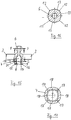
- Figures 11-17 a second embodiment of members 2, which as in Figure 1 of the first exemplary embodiment described above can be assembled to form a line routing device.
- the guide elements 5 extending around the central joint body 5 are rectangular, with two guide elements 3 being connected to one another and formed on the central joint body 5 via a web 10.
- the two webs 10 are arranged in alignment with one another and are integrally formed on the central joint body 5 at radially opposite points.
- the circumferential geometry has four regular corner points 12 which are connected to one another by convexly curved side lines 13 of the same curvature.
- the radius of curvature of the side lines 13 is in turn greater than the radius of the smallest circle surrounding the corner points 12 and the side lines 13.
- the webs 10 connecting the central joint body 5 to the guide elements 3 are integrally formed in the middle area of the outer sides of two opposite sides of the joint socket 7, which in turn are designed as tongues 18, in particular from the Figures 11, 13 and 14 emerges.
Description
Die vorliegende Erfindung betrifft eine Leitungsführungseinrichtung aus gelenkig miteinander verbundenen stirnseitig offenen Gliedern, die in Längsrichtung der Leitungsführungseinrichtung hintereinander angeordnet sind und mittels radial außenseitiger Führungselemente einen Führungskanal zur Aufnahme und Führung von Energie- und/oder Informationsleitungen bilden, wobei die Glieder innerhalb des Führungskanals jeweils einen zentralen Gelenkkörper zur gelenkigen Verbindung unmittelbar benachbarter Glieder aufweisen, der einen Gelenkkopf und eine Gelenkpfanne mit einer Öffnung zum Einsetzen des Gelenkkopfes eines unmittelbar benachbarten Gliedes umfasst, wobei die Gelenkpfanne einen ersten Aufnahmebereich aufweist, in dem der darin eingesetzte Gelenkkopf eines unmittelbar benachbarten Gliedes gegen Verdrehung um die Längsachse der Leitungsführungseinrichtung gesichert ist, und wobei unmittelbar benachbarte Glieder in mindestens zwei unterschiedlichen Abwinkelungsebenen gegenüber der Längsachse der Leitungsführungseinrichtung abwinkelbar sind.The present invention relates to a line routing device made of hingedly interconnected, end-open links which are arranged one behind the other in the longitudinal direction of the line routing device and, by means of radially outer guide elements, form a guide channel for receiving and guiding power and / or information lines, the links each having one inside the guide channel have a central joint body for the articulated connection of immediately adjacent links, which comprises a joint head and a joint socket with an opening for inserting the joint head of an immediately adjacent link, the joint socket having a first receiving area in which the joint head of an immediately adjacent link inserted therein against rotation the longitudinal axis of the line routing device is secured, and wherein directly adjacent links in at least two different planes of angling with respect to the longitudinal axis of the line routing device are angled.
Die radial außenseitigen Führungselemente können sich bogenförmig oder rechteckig um den zentralen Gelenkkörper erstrecken und durch Stege mit dem Gelenkkörper verbunden sein. Die Führungselemente unmittelbar benachbarter Glieder können in einem Abstand voneinander angeordnet sein oder sich gegenseitig überlappen, so dass sie auch bei gegeneinander abgewinkelten Gliedern eine geschlossene, rohrförmige Leitungsführungseinrichtung bilden.The radially outer guide elements can extend arcuately or rectangularly around the central joint body and be connected to the joint body by webs. The guide elements of directly adjacent links can be arranged at a distance from one another or overlap one another so that they form a closed, tubular line guide device even when the links are angled against one another.
Der Gelenkkopf eines Gelenkkörpers soll in der Gelenkpfanne eines unmittelbar benachbarten Gliedes verrastbar sein, so dass die Gelenkverbindung auf diese wirkende Zugkräfte aufnehmen kann.The joint head of a joint body should be latchable in the joint socket of an immediately adjacent link, see above that the joint connection can absorb tensile forces acting on this.
Eine Leitungsführungseinrichtung der eingangs genannten Art ist aus der
Eine Leitungsführungseinrichtung der eingangs genannten Art ist aus der
Die aus der genannten Druckschrift bekannte Verdrehsicherung weist den Nachteil auf, dass bei auf die Gelenkverbindungen wirkenden Drehmomenten um die Längsachse der Leitungsführungseinrichtung relativ kleine Seitenflächen der Zapfen und Anlageflächen der Führungsschlitze die Drehmomente aufnehmen müssen und daher die Verdrehsicherung bei größeren auf die Gelenkverbindungen wirkenden Drehmomenten verschleißanfällig ist. Weiterhin ist die seitliche Wandung der Gelenkpfanne im Bereich ihres Aufnahmebereichs für den Gelenkkopf durch die Führungsschlitze unterbrochen, die eine ausreichende Breite zur Aufnahme der die Verdrehsicherung herstellenden Zapfen besitzen müssen. Die entsprechend dem Durchmesser der Zapfen beabstandeten Zungen der Gelenkpfanne können sich bei starken auf die Gelenkverbindung wirkenden Zugkräften aufspreizen, so dass die Gelenkverbindung unter Umständen keine ausreichende Stabilität besitzt. Hinzu kommt, dass beim Zusammensetzen der Glieder eine genaue Justierung der Zapfen des Gelenkkopfes eines Gliedes in Bezug auf die Führungsschlitze in der Gelenkpfanne eines benachbarten Gliedes notwendig ist.The anti-rotation device known from the cited publication has the disadvantage that when torques act on the articulated connections around the longitudinal axis of the line guide device, relatively small side surfaces of the pins and contact surfaces of the guide slots have to absorb the torques, and therefore the anti-rotation device is prone to wear when larger torques act on the articulated connections . Furthermore, the side wall of the joint socket is interrupted in the area of its receiving area for the joint head by the guide slots, which must have a sufficient width to accommodate the pins producing the anti-rotation device. The tongues of the joint socket, which are spaced apart according to the diameter of the pegs, can spread open in the event of strong tensile forces acting on the joint connection, so that the joint connection may not have sufficient stability. In addition, when assembling the links, precise adjustment of the pins of the joint head of one link in relation to the guide slots in the joint socket of an adjacent link is necessary.
Die
Aus der
Die
Die vorstehende Aufgabe wird erfindungsgemäß dadurch gelöst, dass der Gelenkkopf einen axialen Bereich bezüglich der Längsachse der Leitungsführungseinrichtung aufweist, in dem der Querschnitt des Gelenkkopfes eine Umfangsgeometrie mit mindestens zwei Eckpunkten und diese miteinander verbindenden Seitenlinien aufweist, wobei für alle Eckpunkte der Umfangsgeometrie die an einem Eckpunkt sich treffenden Seitenlinien einen Innenwinkel von kleiner 180° einschließen, und die Gelenkpfanne einen zum axialen Bereich des Gelenkkopfes geometrisch korrespondierenden ersten Aufnahmebereich aufweist, in den der Gelenkkopf einrastbar ist, so dass der mit dem axialen Bereich in dem ersten Aufnahmebereich der Gelenkpfanne eines Gliedes sitzende Gelenkkopf eines unmittelbar benachbarten Gliedes darin unverdrehbar angeordnet und in zumindest zwei unterschiedlichen Abwinkelungsebenen abwinkelbar ist.The above object is achieved according to the invention in that the joint head has an axial area with respect to the longitudinal axis of the line guide device, in which the cross section of the joint head has a circumferential geometry with at least two corner points and side lines connecting these with each other, with the one at a corner point for all corner points of the circumferential geometry The lateral lines that meet each other enclose an interior angle of less than 180 °, and the joint socket has a first receiving area which corresponds geometrically to the axial area of the joint head and into which the joint head can be locked so that the joint head sitting with the axial area in the first receiving area of the joint socket of a member of an immediately adjacent link is arranged therein so that it cannot rotate and can be angled in at least two different angled planes.
Aufgrund der mindestens zwei Eckpunkte und diese miteinander verbindenden Seitenlinien aufweisenden Querschnittsgeometrie des Gelenkkopfes und des Aufnahmebereichs der Gelenkpfanne wird eine Verdrehsicherung ermöglicht, bei der sich im Wesentlichen über den gesamten Umfang des Gelenkkopfes und des Aufnahmebereichs der Gelenkpfanne erstreckende Flächen aneinander anliegen und Drehmomente um die Achsen der Gelenkverbindungen zwischen benachbarten Gliedern aufnehmen. Durch die flächige Anlage wird ein durch Drehmomente verursachter Verschleiß weitestgehend vermieden. Weiterhin ermöglicht die Querschnittsgeometrie eine Selbstjustierung des Gelenkkopfes in Bezug auf den Aufnahmebereich der Gelenkpfanne, da die durch elastisches Aufweiten der Öffnung der Gelenkpfanne beim Einführen des Gelenkkopfes auf dessen Eckpunkte wirkenden Kräfte die Eckpunkte entlang der Seitenlinien des Aufnahmebereichs zu dessen Eckpunkten hin führen.Due to the cross-sectional geometry of the joint head and the receiving area of the joint socket, which has at least two corner points and these side lines connecting them, a rotation lock is made possible in which surfaces extending essentially over the entire circumference of the joint head and the receiving area of the joint socket rest against one another and torques about the axes of the Include articulated connections between adjacent links. Wear caused by torques is largely avoided due to the flat contact. Furthermore, the Cross-sectional geometry a self-adjustment of the joint head in relation to the receiving area of the joint socket, since the forces acting on its corner points due to the elastic widening of the opening of the joint socket when the joint head is inserted lead the corner points along the side lines of the receiving area to its corner points.
Die Querschnittsgeometrien des Aufnahmebereichs der Gelenkpfanne und des axialen Bereichs eines in der Gelenkpfanne sitzenden Gelenkkopfes können längs des gesamten axialen Bereichs einander entsprechen. Die Querschnittsgeometrien können auch derart zueinander ähnlich sein, dass sich ein geringes Spiel zwischen dem Aufnahmebereich der Gelenkpfanne und einem in dieser sitzenden Gelenkkopf eines benachbarten Gliedes ergibt. Alternativ können die Querschnittsgeometrien auch derart ähnlich sein, dass der Gelenkkopf eines benachbarten Gliedes mit einem geringen Presssitz im Aufnahmebereich der Gelenkpfanne sitzt.The cross-sectional geometries of the receiving area of the joint socket and of the axial area of a joint head seated in the joint socket can correspond to one another along the entire axial area. The cross-sectional geometries can also be similar to one another in such a way that there is a slight play between the receiving area of the joint socket and a joint head of an adjacent link seated in it. Alternatively, the cross-sectional geometries can also be similar in such a way that the joint head of an adjacent link sits with a slight press fit in the receiving area of the joint socket.
Die Eckpunkte der Querschnittsgeometrie des Gelenkkopfes und des Aufnahmebereichs der Gelenkpfanne können über die Höhe des axialen Bereichs durchgehende Kanten bilden, zwischen denen sich in Höhenrichtung des axialen Bereichs konvex gekrümmte, insbesondere kreisbogenförmige, Flächen erstrecken.The corner points of the cross-sectional geometry of the joint head and the receiving area of the joint socket can form continuous edges over the height of the axial area, between which convexly curved, in particular circular arc-shaped, surfaces extend in the height direction of the axial area.
Bevorzugt sind die zentralen Gelenkkörper so ausgebildet, dass unmittelbar benachbarte Glieder in beliebigen Abwinkelungsebenen, die die Längsachse der Leitungsführungseinrichtung gemeinsam haben, abwinkelbar sind.The central joint bodies are preferably designed in such a way that immediately adjacent links can be angled in any desired angled planes which have the longitudinal axis of the line guide device in common.
Die Gelenkkörper können mit dem Gelenkkopf und der Gelenkaufnahme einstückig ausgebildet, insbesondere aus Kunststoff spritzgegossen sein. Die sich radial außenseitig um den zentralen Gelenkkörper erstreckenden Führungselemente können an den zentralen Gelenkkörper über Stege, z. B. durch Spritzguss, angeformt sein. Um besonderen Anforderungen, z. B. an die Elastizität, Härte, der einzelnen Bauteile eines Gliedes Rechnung zu tragen, können die Glieder auch im Mehrkomponenten-Spritzgießverfahren hergestellt werden.The joint bodies can be designed in one piece with the joint head and the joint receptacle, in particular injection molded from plastic. The guide elements extending radially on the outside around the central joint body can be attached to the central joint body via webs, e.g. B. be molded by injection molding. To meet special requirements, e.g. B. to take into account the elasticity, hardness, of the individual components of a link, the links can also be manufactured in multi-component injection molding.
Der Gelenkkörper eines Gliedes weist vorzugsweise in seinem einen axialen Endbereich den Gelenkkopf und in seinem anderen axialen Endbereich die Gelenkpfanne auf. Der Gelenkkopf kann über einen Hals mit kleinerem Durchmesser mit der Gelenkpfanne verbunden sein.The joint body of a link preferably has the joint head in its one axial end area and the joint socket in its other axial end area. The joint head can be connected to the joint socket via a neck with a smaller diameter.
Die Öffnung der Gelenkpfanne zum Einsetzen des Gelenkkopfes kann an der den ersten Aufnahmebereich aufweisenden axialen Stirnseite des zentralen Gelenkkörpers angeordnet sein.The opening of the joint socket for inserting the joint head can be arranged on the axial end face of the central joint body which has the first receiving area.
Die Innenseite des Randbereichs der Öffnung kann eine im geometrischen Sinne ähnliche Umfangsgeometrie zu derjenigen des daran anschließenden ersten Aufnahmebereichs aufweisen, wobei sie eine Verengung gegenüber dem ersten Aufnahmebereich aufweist. Zur Stirnseite der Gelenkpfanne kann sich die Innenseite des Randbereichs der Öffnung zum einfacheren Einbringen und zum möglichen Selbstjustieren des Gelenckopfes in Bezug auf die Umfangsgeometrie des ersten Aufnahmebereichs der Gelenkpfanne nach außen konisch erweitert sein.The inside of the edge region of the opening can have a circumferential geometry that is geometrically similar to that of the adjoining first receiving area, wherein it has a narrowing compared to the first receiving area. Towards the end face of the joint socket, the inside of the edge area of the opening can be conically widened outwards for easier introduction and possible self-adjustment of the joint head in relation to the circumferential geometry of the first receiving area of the joint socket.
Bevorzugt sind die Eckpunkte der Umfangsgeometrie des axialen Bereichs des Gelenkkopfes regelmäßig über die Umfangsgeometrie verteilt.The corner points of the circumferential geometry of the axial area of the joint head are preferably distributed regularly over the circumferential geometry.
Weiterhin sind die die Eckpunkte miteinander verbindenden Seitenlinien vorzugsweise konvex gekrümmt.Furthermore, the side lines connecting the corner points are preferably convexly curved.
Insbesondere können alle die Eckpunkte miteinander verbindenden Seitenlinien den gleichen Krümmungsradius besitzen.In particular, all the side lines connecting the corner points with one another can have the same radius of curvature.
Der Krümmungsradius der die Eckpunkte miteinander verbindenden Seitenlinien ist dann größer als der Radius des kleinsten, die Eckpunkte und die Seitenlinien umschließenden Kreises. Insbesondere können die Radien in einem Verhältnis von 5/4-15/4 stehen.The radius of curvature of the side lines connecting the corner points to one another is then greater than the radius of the smallest one enclosing the corner points and the side lines Circle. In particular, the radii can have a ratio of 5 / 4-15 / 4.
Bevorzugt weist die Umfangsgeometrie des Querschnitts des Gelenkkopfes im axialen Bereich mindestens drei Eckpunkte, insbesondere drei oder vier Eckpunkte, auf.The circumferential geometry of the cross section of the joint head preferably has at least three corner points, in particular three or four corner points, in the axial region.
Die Eckpunkte können abgerundet sein, so dass die daran angrenzenden Seitenlinien im Wesentlichen stetig mit einem kleinen Krümmungsradius ineinander übergehen.The corner points can be rounded so that the side lines adjoining them essentially merge continuously with a small radius of curvature.
In einer bevorzugten Ausführung ist der zum axialen Bereich des Gelenkkopfes geometrisch korrespondierende erste Aufnahmebereich der Gelenkpfanne in axialer Richtung im Bereich zumindest einer Eckkante von der Öffnung her geschlitzt. Der Schlitz kann eine zu vernachlässigende Breite aufweisen und dient lediglich dazu, dass sich der Randbereich der Öffnung und der sich daran anschließende erste Aufnahmebereich der Gelenkpfanne beim Einführen des Gelenkkopfes elastisch aufweiten können. Insbesondere bei konvexer Krümmung der die Eckpunkte miteinander verbindenden Seitenlinien der Querschnittsgeometrie wirkt aufgrund der elastischen Kräfte auf die entsprechend konvex gekrümmten Seitenflächen des Gelenckopfes ein Drehmoment, wenn der Gelenkkopf in die Öffnung der Gelenkpfanne eingeführt und nicht entsprechend der Umfangsgeometrie der Innenseite des Randbereichs der Öffnung und dem daran anschließenden Aufnahmebereich der Gelenkpfanne justiert ist. Das Drehmoment kann in diesem Falle eine Selbstjustierung auf die Umfangsgeometrie der Innenseite des Randbereichs der Öffnung und des daran anschließenden ersten Aufnahmebereichs der Gelenkpfanne bewirken.In a preferred embodiment, the first receiving area of the joint socket, which geometrically corresponds to the axial area of the joint head, is slotted in the axial direction in the area of at least one corner edge from the opening. The slot can have a negligible width and is only used to enable the edge area of the opening and the adjoining first receiving area of the joint socket to expand elastically when the joint head is inserted. Particularly in the case of a convex curvature of the side lines of the cross-sectional geometry connecting the corner points, a torque acts on the correspondingly convex curved side surfaces of the joint head due to the elastic forces when the joint head is inserted into the opening of the joint socket and not in accordance with the circumferential geometry of the inside of the edge area of the opening and the adjoining receiving area of the joint socket is adjusted. In this case, the torque can bring about a self-adjustment to the circumferential geometry of the inside of the edge area of the opening and the adjoining first receiving area of the joint socket.
In einer Weiterbildung der Erfindung kann die Gelenkpfanne eines Gliedes der Leitungsführungseinrichtung einen sich an den ersten Aufnahmebereich in von der Öffnung der Gelenkpfanne wegweisender Richtung anschließenden zweiten Aufnahmebereich aufweisen, in den der Gelenkkopf eines unmittelbar benachbarten Gliedes aus dem ersten Aufnahmebereich einrastbar ist, wobei die beiden Glieder so ausgestaltet sind, dass ihre Abwinkelung relativ zueinander in zumindest einer Abwinkelungsrichtung blockiert ist, wenn der Gelenkkopf im zweiten Aufnahmebereich der Gelenkpfanne sitzt.In a further development of the invention, the joint socket of a member of the line guide device can have a second receiving area adjoining the first receiving area in a direction pointing away from the opening of the joint socket, into which the joint head of a directly adjacent link from the first receiving area can be latched, the two links being designed so that their bending relative to one another is blocked in at least one bending direction when the joint head is seated in the second receiving area of the joint socket.
Der zweite Aufnahmebereich kann vom ersten Aufnahmebereich durch einen Überlappungsbereich getrennt sein, dessen Innendurchmesser kleiner ist als der größte Außendurchmesser des Gelenkkopfes. Der Innendurchmesser dieser Verengung ist bevorzugt größer als der Innendurchmesser der Verengung an der Innenseite des Randbereichs der Öffnung der Gelenkpfanne, um den Gelenkkopf mit einer geringeren Kraft aus der Rastverbindung mit dem zweiten Aufnahmebereich zu entfernen als derjenigen Kraft, die zur Entfernung des Gelenkkopfes aus dem ersten Aufnahmebereich erforderlich ist.The second receiving area can be separated from the first receiving area by an overlapping area, the inner diameter of which is smaller than the largest outer diameter of the joint head. The inner diameter of this constriction is preferably greater than the inner diameter of the constriction on the inside of the edge area of the opening of the joint socket in order to remove the joint head from the latching connection with the second receiving area with a lower force than the force required to remove the joint head from the first Recording area is required.
Zum Entfernen des Gelenkkopfes aus der Rastverbindung mit dem ersten Aufnahmebereich der Gelenkpfanne können eine oder mehrere stirnseitig offene Ausnehmungen im Randbereich der Gelenkpfanne vorgesehen sein, durch die ein Werkzeug einführbar ist, das mit einem Ende an dem in der Gelenkpfanne sitzenden Gelenkkopf angreift und den Endbereich der Gelenkpfanne mit der innenseitigen Verengung nach außen aufhebeln kann, um den Gelenkkopf leichter aus der Gelenkpfanne zu entfernen.To remove the joint head from the snap-in connection with the first receiving area of the joint socket, one or more recesses open at the end can be provided in the edge area of the joint socket, through which a tool can be inserted that engages with one end of the joint head seated in the joint socket and the end area of the Can pry open the joint socket with the narrowing on the inside, in order to remove the joint head more easily from the joint socket.
Bevorzugt weist der Gelenkkopf einen Hals mit einem gegenüber ihm kleineren Außendurchmesser auf, der über einen sich konisch verbreiternden Bereich mit der Gelenkpfanne verbunden ist, wobei der sich konisch verbreiternde Bereich eine im geometrischen Sinne ähnliche Querschnittsgeometrie aufweist wie der erste Aufnahmebereich der Gelenkpfanne und diese Querschnittsgeometrie mit derjenigen des nach außen konisch erweiterten Bereichs der Öffnung der Gelenkpfanne korrespondiert. Die Gelenkkörper der Glieder sind dann so ausgebildet, dass beim Einbringen des Gelenkkopfes eines Gliedes in den zweiten Aufnahmebereich der Gelenkpfanne eines unmittelbar benachbarten Gliedes der sich an den Hals des Gelenkkopfes anschließende konisch verbreiternde Bereich aufgrund der miteinander korrespondierenden Querschnittsgeometrie mit dem sich nach außen konisch verbreiternden Bereich der Öffnung der Gelenkpfanne zusammenwirkt und eine Verdrehsicherung in dieser Verbindungsstellung der Gelenckörper bewirkt.The joint head preferably has a neck with an outer diameter that is smaller than that, which is connected to the joint socket via a conically widening area, the conically widening area having a cross-sectional geometry that is geometrically similar to the first receiving area of the joint socket and this cross-sectional geometry that of the outwardly conically widened area of the opening of the joint socket corresponds. The joint bodies of the links are then designed so that when the joint head is inserted, one Link in the second receiving area of the joint socket of a directly adjacent link, the conically widening area adjoining the neck of the joint head interacts with the outwardly conically widening area of the opening of the joint socket due to the mutually corresponding cross-sectional geometry and provides a rotation lock in this connection position of the joint body.
Die Verdrehsicherung in dieser Stellung kann alternativ oder zusätzlich dadurch bewirkt werden, dass der zweite Aufnahmebereich und optional auch der verengte Übergangsbereich zwischen dem ersten und zweiten Aufnahmebereich der Gelenkpfanne eine zum ersten Aufnahmebereich ähnliche Querschnittsgeometrie aufweisen.The anti-rotation device in this position can alternatively or additionally be effected in that the second receiving area and optionally also the narrowed transition area between the first and second receiving area of the joint socket have a cross-sectional geometry similar to the first receiving area.
Die erfindungsgemäße Leitungsführungseinrichtung ist insbesondere zur Aufnahme und Führung von Energie- und/oder Informationsleitungen im Möbelbereich, insbesondere bei Büromöbeln, konzipiert. Sie kann jedoch generell im Gebäudebereich und im Maschinenbau, z. B. in der Robotik eingesetzt werden, insbesondere auch zur Versorgung beweglicher Maschinenteile oder Einheiten mit Energie und/oder Information.The line routing device according to the invention is designed in particular for receiving and routing energy and / or information lines in the furniture sector, in particular in office furniture. However, it can generally be used in the building sector and in mechanical engineering, e.g. B. be used in robotics, in particular to supply moving machine parts or units with energy and / or information.
Zwei Ausführungsbeispiele der vorliegenden Erfindung werden im Folgenden anhand der Zeichnung näher erläutert.Two exemplary embodiments of the present invention are explained in more detail below with reference to the drawing.
In der Zeichnung zeigen:
Figur 1- eine perspektivische Ansicht eines drei Glieder umfassenden Abschnitts einer Leitungsführungseinrichtung,
Figur 2- eine Seitenansicht des in
Figur 1 Figur 3- einen Längsschnitt durch den in
Figur 2 Figur 4- Schnitt längst der Linie A-A in
Figur 2 Figur 5- eine Seitenansicht eines Gliedes mit gestrichelt gezeichneten verdeckten Linien,
Figur 6- stirnseitige Ansicht von oben auf das in
Figur 5 Figur 7- stirnseitige Ansicht von unten auf das in
Figur 5 Figur 8- Schnitt längs der Linie B-B in
Figur 5 Figur 9- Schnitt längs der Linie D-D in
Figur 8 Figur 10- Schnitt längs der Linie E-E in
Figur 8 Figur 11- eine zweite Ausführung eines Gliedes einer Leitungsführungseinrichtung,
Figur 12- seitliche Ansicht des in
Figur 11 Figur 13- stirnseitige Ansicht von oben auf das in
Figur 12 Figur 14- stirnseitige Ansicht von unten auf das in
Figur 12 Figur 15- Schnitt längs der Linie C-C in
Figur 12 Figur 16- Schnitt längs der Linie F-F in
Figur 15 Figur 17- Schnitt längs der Linie G-G in
Figur 15
- Figure 1
- a perspective view of a three-link section of a line guide device,
- Figure 2
- a side view of the in
Figure 1 shown section of a line routing device, - Figure 3
- a longitudinal section through the in
Figure 2 illustrated section of a line routing device parallel to the drawing plane, - Figure 4
- Cut along line AA in
Figure 2 , - Figure 5
- a side view of a link with hidden lines drawn in dashed lines,
- Figure 6
- frontal view from above of the in
Figure 5 shown link, - Figure 7
- frontal view from below of the in
Figure 5 shown link, - Figure 8
- Section along the line BB in
Figure 5 , - Figure 9
- Section along line DD in
Figure 8 , - Figure 10
- Section along the line EE in
Figure 8 , - Figure 11
- a second embodiment of a link of a line routing device,
- Figure 12
- side view of the in
Figure 11 shown limb, - Figure 13
- frontal view from above of the in
Figure 12 shown link, - Figure 14
- frontal view from below of the in
Figure 12 shown link, - Figure 15
- Section along the line CC in
Figure 12 , - Figure 16
- Section along the line FF in
Figure 15 and - Figure 17
- Section along the line GG in
Figure 15 .
Wie aus dem in
Die Glieder 2 weisen innerhalb des Führungskanals 4 jeweils einen zentralen Gelenkkörper 5 zur gelenkigen Verbindung unmittelbar benachbarter Glieder 2 auf, der einen Gelenkkopf 6 und eine Gelenkpfanne 7 mit einer Öffnung 8 zum Einsetzen des Gelenkkopfes 6 eines unmittelbar benachbarten Gliedes 2 umfasst.The
Wie insbesondere aus
Wie ebenfalls in den
Der Gelenkkopf 6 des in den
Wie genauer aus den
Die insbesondere aus
Wie insbesondere aus den
Die Öffnung 8 der Gelenkpfanne 7 zum Einsetzen des Gelenckopfes 6 eines unmittelbar benachbarten Gliedes 2 ist an der den ersten Aufnahmebereich 9 aufweisenden axialen Stirnseite 14 des zentralen Gelenkkörpers 5 angeordnet. Die Innenseite des Randbereichs 15 der Öffnung 8 weist eine im geometrischen Sinne ähnliche Umfangsgeometrie zu derjenigen des daran anschließenden ersten Aufnahmebereichs 9 auf, wobei sie eine Verengung 15 gegenüber dem ersten Aufnahmebereich 9 einschließt. Zur axialen Stirnseite 14 der Gelenkpfanne 7 hin weist die Innenseite einen sich von der Verengung 15 nach außen erstreckenden konisch erweiterten Bereich 16 auf, der ein einfaches Einbringen des Gelenkkopfes 6 in den ersten Aufnahmebereich 9 der Gelenkpfanne 7 und ein dabei erfolgendes Selbstjustieren des Gelenkkopfes 6 in Bezug auf die Umfangsgeometrie des ersten Aufnahmebereichs 9 der Gelenkpfanne 7 ermöglicht.The
Wie insbesondere aus den
Wie weiterhin aus den
Um in dieser Stellung die beiden unmittelbar benachbarten Glieder 2 ebenfalls gegen ein Verdrehen relativ zueinander um die Längsachse A zu sichern, ist der Hals des Gelenkkopfes 6 über einen sich konisch verbreiternden Bereich 20 mit der in ihrer äußeren Form zylindrischen Gelenkpfanne 7 verbunden. Der sich konisch verbreiternde Bereich 20 weist eine im geometrischen Sinne ähnliche Querschnittsgeometrie bezüglich der Längsachse der Gelenkpfanne 7 auf, wie der erste Aufnahmebereich 9 der Gelenkpfanne 7 und korrespondiert mit der Querschnittsgeometrie des nach außen erweiterten Bereichs 16 der Öffnung 8 der Gelenkpfanne 7.In order to prevent the two immediately
Die Verdrehsicherung in dieser Stellung kann zusätzlich dadurch bewirkt werden, dass der zweite Aufnahmebereich 19 sowie auch der verengte Übergangsbereich 21 zwischen dem ersten und zweiten Aufnahmebereich der Gelenkpfanne 7 eine mit der Querschnittsgeometrie des axialen Bereichs 11 des Gelenkkopfes 5 im geometrischen Sinne ähnliche Querschnittsgeometrie aufweisen.The anti-twist protection in this position can also be effected in that the
Der Innendurchmesser des verengten Übergangsbereichs 21 zwischen dem ersten und zweiten Aufnahmebereich der Gelenkpfanne 7 ist etwas größer als der Innendurchmesser der Verengung 15 an der Innenseite des Randbereichs der Öffnung 8 der Gelenkpfanne 7, um den Gelenkkopf 6 mit einer geringeren Kraft aus der Rastverbindung mit dem zweiten Aufnahmebereich 19 zu entfernen als derjenigen Kraft, die zur Entfernung des Gelenkkopfes 6 aus dem ersten Aufnahmebereich 9 erforderlich ist.The inner diameter of the narrowed
Zum Entfernen des Gelenkkopfes 6 aus der Rastverbindung mit dem ersten Aufnahmebereich 9 der Gelenkpfanne 7 sind stirnseitig offene Ausnehmungen 22 im Randbereich der Zungen 18 der Gelenkpfanne 7 vorgesehen, durch die ein in der Zeichnung nicht dargestelltes Werkzeug einführbar ist, das mit einem Ende an dem in der Gelenkpfanne 7 sitzenden Gelenkkopf 6 angreift und den Endbereich der betreffenden Zunge 18 mit der innenseitigen Verengung 15 nach außen aufhebeln kann, um den Gelenkkopf 6 leichter aus der Gelenkpfanne 7 zu entfernen.To remove the
In der Zeichnung stellen die
Im Unterschied zum ersten Ausführungsbeispiel sind die sich um die zentralen Gelenkkörper 5 erstreckenden Führungselemente 5 rechteckig ausgebildet, wobei jeweils zwei Führungselemente 3 miteinander verbunden und über einen Steg 10 an dem zentralen Gelenkkörper 5 angeformt sind. Die beiden Stege 10 sind fluchtend zueinander angeordnet und an radial gegenüberliegenden Stellen am zentralen Gelenkkörper 5 angeformt.In contrast to the first exemplary embodiment, the
Dadurch bietet sich eine etwas andere Umfangsgeometrie des zentralen Gelenkkörpers sowie des ersten und teilweise zweiten Aufnahmebereichs der Gelenkpfanne 7 einschließlich des Übergangsbereichs 21 zwischen den beiden Aufnahmebereichen, der sich in Richtung auf die axiale Stirnseite 14 der Gelenkpfanne 7 an den ersten Aufnahmebereich 9 anschließenden Verengung 15 und des sich an diese anschließenden nach außen erweiterten Bereichs 16 an.This offers a somewhat different circumferential geometry of the central joint body and of the first and partially second receiving area of the
Wie insbesondere aus den
Zweckmäßigerweise sind die den zentralen Gelenkkörper 5 mit den Führungselementen 3 verbindenden Stege 10 im mittleren Bereich der Außenseiten zweier gegenüberliegender Seiten der Gelenkpfanne 7, die wiederum als Zungen 18 ausgebildet sind, angeformt, wie insbesondere aus den
- 11
- LeistungsführungseinrichtungPerformance management device
- 22
- Gliedelement
- 33
- FührungselementGuide element
- 44th
- FührungskanalGuide channel
- 55
- GelenkkörperJoint body
- 66th
- GelenkkopfSwivel head
- 77th
- GelenkpfanneSocket
- 88th
- Öffnungopening
- 99
- erster Aufnahmebereichfirst recording area
- 1010
- Stegweb
- 1111
- axialer Bereichaxial area
- 1212
- EckpunktCorner point
- 1313
- SeitenlinieSideline
- 1414th
- axiale Stirnseiteaxial face
- 1515th
- VerengungNarrowing
- 1616
- erweiterter Bereichextended area
- 1717th
- Schlitzslot
- 1818th
- Zungetongue
- 1919th
- zweiter Aufnahmebereichsecond recording area
- 2020th
- sich verbreiternder Bereichwidening area
- 2121st
- ÜbergangsbereichTransition area
- 2222nd
- AusnehmungRecess
- AA.
- Längsachse der LeitungsführungseinrichtungLongitudinal axis of the line guide device
Claims (15)
- Line-guiding device (1) composed of members (2), connected to one another in an articulated manner and open at their end faces, which are arranged one behind the other in the longitudinal direction of the line-guiding device (1) and form, by means of radially outer guide elements (3), a guide channel (4) for receiving and guiding energy and/or information cables, wherein the members (2) each have inside the guide channel (4) a central joint body (5) for the articulated connection of immediately adjacent members (2), which joint body comprises a joint head (6) and a joint socket (7) having an opening (8) for insertion of the joint head (6) of an immediately adjacent member (2), wherein the joint socket (7) comprises a first receiving region (9) in which the joint head (6) inserted therein of an immediately adjacent member (2) is secured against rotation about the longitudinal axis (A) of the line-guiding device (1), and wherein immediately adjacent members (2) can be angled relative to the longitudinal axis (A) of the line-guiding device (1) in at least two different angling planes, characterized in that the joint head (6) comprises an axial region (11) relative to the longitudinal axis (A) of the line-guiding device (1) in which the cross-section of the joint head (6) comprises a peripheral geometry with at least two vertices (12) and lateral lines (13) connecting the vertices together, wherein, for all the vertices (12) of the peripheral geometry, the lateral lines (13) meeting at a vertex (12) enclose an internal angle of less than 180°, and the joint socket (7) comprises a first receiving region (9) corresponding geometrically to the axial region (11) of the joint head (6), in which receiving region (9) the joint head (6) can be locked, so that the joint head (6) of an immediately adjacent member (2) seated with the axial region (11) in the first receiving region (9) of the joint socket (7) of a member (2) is arranged non-rotatably therein and can be angled in at least two different angular planes.
- Line-guiding device (1) according to claim 1,
characterized in that the central joint bodies (5) are formed such that immediately adjacent members (2) can be angled in any desired angular planes which have the longitudinal axis (A) of the line-guiding device (1) in common. - Line-guiding device (1) according to claim 1 or 2,
characterized in that the central joint bodies (5) are formed in one piece, in particular are injection molded from plastics material. - Line-guiding device (1) according to any one of claims 1 to 3, characterized in that the joint body (5) of a member (2) comprises the joint head (6) in one axial end region and the joint socket (7) in its other axial end region.
- Line-guiding device (1) according to claim 4,
characterized in that the opening (8) of the joint socket (7) for insertion of the joint head (6) is arranged at the axial end face (14) of the central joint body (5) having the first receiving region (9) of the joint socket (7) . - Line-guiding device (1) according to any one of claims 1 to 5, characterized in that the inside of the edge region of the opening (8) has a peripheral geometry which is similar in the geometrical sense to that of the adjacent first receiving region (9), wherein it comprises a narrowing (15) relative to the first receiving region (9) .
- Line-guiding device (1) according to any one of claims 1 to 6, characterized in that the vertices (12) of the peripheral geometry of the axial region (11) of the joint head (6) are distributed evenly over the peripheral geometry.
- Line-guiding device (1) according to any one of claims 1 to 7, characterized in that the lateral lines (13) connecting the vertices (12) together are convexly curved.
- Line-guiding device (1) according to claim 8,
characterized in that all the lateral lines (13) connecting the vertices (12) together have the same radius of curvature. - Line-guiding device (1) according to claim 9,
characterized in that the radius of curvature of the lateral lines (13) connecting the vertices (12) together is larger than the radius of the smallest circle enclosing the vertices (12) and the lateral lines (13), wherein the radii can in particular be in a ratio of from 5/4 to 15/4. - Line-guiding device (1) according to any one of claims 1 to 10, characterized in that the peripheral geometry of the cross-section of the joint head (6) in the axial region (11) comprises at least three vertices (12), in particular three or four vertices (12).
- Line-guiding device (1) according to any one of claims 1 to 11, characterized in that the first receiving region (9), corresponding geometrically to the axial region (11) of the joint head (6), of the joint socket (7) is slotted from the opening (8) in the axial direction in the region of at least one corner edge defined by the vertices (12).
- Line-guiding device (1) according to any one of claims 1 to 12, characterized in that the joint socket (7) of a member (2) of the line-guiding device (1) comprises a second receiving region (19) adjacent to the first receiving region (9) in the direction facing away from the opening (8) of the joint socket (7), in which second receiving region the joint head (6) of an immediately adjacent member (2) can be engaged from the first receiving region (9), wherein the two members (2) are formed such that angling thereof relative to one another is blocked in at least one angling direction when the joint head (6) is seated in the second receiving region (19) of the joint socket (7).
- Line-guiding device (1) according to claim 13,
characterized in that the second receiving region (19) is separated from the first receiving region (9) by a transition region (21), the inside diameter of which is smaller than the largest outside diameter of the joint head (6) and larger than the inside diameter of the narrowing (15) on the inside of the edge region of the opening (8) of the joint socket (7). - Line-guiding device (1) according to claim 13 or 14,
characterized in that the joint head (6) comprises a neck with a smaller diameter relative to the joint head, which neck is connected to the joint socket (7) via a conically widened region (20), wherein the conically widened region (20) has a cross-sectional geometry which is similar in the geometrical sense to that of the first receiving region (9) of the joint socket (7), and that cross-sectional geometry corresponds to that of the outwardly conically widened region (16) of the opening (8) of the joint socket (7).
Applications Claiming Priority (2)
| Application Number | Priority Date | Filing Date | Title |
|---|---|---|---|
| DE202017101896.2U DE202017101896U1 (en) | 2017-03-31 | 2017-03-31 | Cable guide |
| PCT/EP2018/057245 WO2018177862A1 (en) | 2017-03-31 | 2018-03-22 | Cable-routing device |
Publications (2)
| Publication Number | Publication Date |
|---|---|
| EP3602709A1 EP3602709A1 (en) | 2020-02-05 |
| EP3602709B1 true EP3602709B1 (en) | 2021-02-24 |
Family
ID=61868507
Family Applications (1)
| Application Number | Title | Priority Date | Filing Date |
|---|---|---|---|
| EP18714998.4A Active EP3602709B1 (en) | 2017-03-31 | 2018-03-22 | Cable-routing device |
Country Status (6)
| Country | Link |
|---|---|
| US (1) | US11462893B2 (en) |
| EP (1) | EP3602709B1 (en) |
| CN (1) | CN110476311B (en) |
| DE (1) | DE202017101896U1 (en) |
| ES (1) | ES2869231T3 (en) |
| WO (1) | WO2018177862A1 (en) |
Families Citing this family (8)
| Publication number | Priority date | Publication date | Assignee | Title |
|---|---|---|---|---|
| DE102019207044A1 (en) * | 2019-05-15 | 2020-11-19 | Siemens Healthcare Gmbh | Energy guiding chain for the movable mounting of at least one flexible, in particular current-carrying, line, use of the energy guiding chain and medical imaging device |
| US11258242B2 (en) * | 2019-08-13 | 2022-02-22 | BL United, LLC | Modular conduit cable management assembly |
| CN112160979B (en) * | 2020-09-10 | 2021-12-17 | 北京交通大学 | U-pair hinge |
| CN112260174A (en) * | 2020-10-31 | 2021-01-22 | 江苏科瑞斯机件有限公司 | Quick assembly disassembly threading guide chain |
| CN112952727B (en) * | 2021-02-07 | 2022-09-09 | 中国科学院合肥物质科学研究院 | Large-capacity rotary drag chain |
| DE202021100995U1 (en) | 2021-02-26 | 2022-05-30 | Igus Gmbh | Spatially deflectable line guiding device, in particular for a robot |
| CN113595019B (en) * | 2021-06-16 | 2023-03-28 | 平高集团有限公司 | Soft wire end fixing fitting |
| PL442460A1 (en) * | 2022-10-06 | 2024-04-08 | Splast Spółka Z Ograniczoną Odpowiedzialnością | Cable guide |
Family Cites Families (15)
| Publication number | Priority date | Publication date | Assignee | Title |
|---|---|---|---|---|
| IT208046Z2 (en) * | 1986-09-15 | 1988-03-31 | Tecno Mobili E Forniture Per A | FLEXIBLE CABLE ORGAN WITH BIDIRECTIONAL JOINTS. |
| US5824957A (en) * | 1991-09-03 | 1998-10-20 | Technology Finance Corporation (Proprietary) Limited | Electrical cable containment |
| DE19617900A1 (en) | 1995-05-10 | 1996-12-05 | Ernst Moeckl | Protective chain unit for electrical cables |
| IT1317520B1 (en) | 2000-05-11 | 2003-07-09 | Traversa Ezio Plastici | MODULAR AND ADJUSTABLE ELEMENTS FOR CABLE DUCTS. |
| IT1318950B1 (en) * | 2000-10-02 | 2003-09-19 | Gianfranchi Pier Luigi | MODULAR CHANNEL FOR CONFINING ELECTRIC AND SIMILAR CABLES. |
| DE20305487U1 (en) * | 2003-04-03 | 2003-06-12 | Igus Gmbh | Guide for cables and hoses has two part sections which can link to one another at an angle and are connected inside the guide channel |
| DE20305680U1 (en) * | 2003-04-07 | 2003-07-17 | Igus Gmbh | Cable guideway of hinged links, each angled in several directions and open at front, fitted behind each other in longitudinal direction of guideway |
| DE20317827U1 (en) * | 2003-11-18 | 2005-03-31 | Ruettiger Maximilian | Conduit link housing for wiring or hose has rail sockets and sockets are located on a common cross-piece |
| DE102007017940A1 (en) * | 2007-04-13 | 2008-10-16 | Igus Gmbh | Side wall segment for a cable guide device, line guide device with side wall segment and method for producing the side wall segment |
| DE202009005650U1 (en) | 2009-04-17 | 2009-07-02 | Igus Gmbh | Power supply chain |
| DE102010032920C5 (en) * | 2010-07-30 | 2023-03-02 | Tsubaki Kabelschlepp GmbH | Spatially deflectable cable routing device with bend radius limiters |
| CN204793903U (en) * | 2015-07-15 | 2015-11-18 | 季德贵 | Can cross line hinge |
| EP3365715B1 (en) * | 2015-10-19 | 2020-12-02 | Commscope Technologies LLC | Articulating optical fiber guide system |
| CN205533751U (en) * | 2016-01-15 | 2016-08-31 | 济南思漫设备科技有限公司 | Spherical hinge chain that can hold cable |
| EP3402026B1 (en) * | 2017-05-11 | 2020-07-08 | HellermannTyton GmbH | Assembly of cable channel modules |
-
2017
- 2017-03-31 DE DE202017101896.2U patent/DE202017101896U1/en active Active
-
2018
- 2018-03-22 CN CN201880023444.3A patent/CN110476311B/en active Active
- 2018-03-22 US US16/499,519 patent/US11462893B2/en active Active
- 2018-03-22 WO PCT/EP2018/057245 patent/WO2018177862A1/en active Application Filing
- 2018-03-22 ES ES18714998T patent/ES2869231T3/en active Active
- 2018-03-22 EP EP18714998.4A patent/EP3602709B1/en active Active
Non-Patent Citations (1)
| Title |
|---|
| None * |
Also Published As
| Publication number | Publication date |
|---|---|
| CN110476311A (en) | 2019-11-19 |
| DE202017101896U1 (en) | 2018-07-04 |
| EP3602709A1 (en) | 2020-02-05 |
| CN110476311B (en) | 2021-01-05 |
| US20200044425A1 (en) | 2020-02-06 |
| WO2018177862A1 (en) | 2018-10-04 |
| US11462893B2 (en) | 2022-10-04 |
| ES2869231T3 (en) | 2021-10-25 |
Similar Documents
| Publication | Publication Date | Title |
|---|---|---|
| EP3602709B1 (en) | Cable-routing device | |
| EP2694841B1 (en) | Cable carrier chain with deformable joint elements | |
| DE102006005998B4 (en) | Nut with at least two parts | |
| DE2941008C2 (en) | frame | |
| EP1969279B1 (en) | Coupling part for a plug connector arrangement | |
| EP0599784A1 (en) | Socket for a fibre optic connection terminal | |
| DE19710489A1 (en) | Foldable protective element for cables | |
| EP1977677A1 (en) | Endoscopic instrument | |
| EP0615071A2 (en) | Plastic retaining element | |
| EP3096025A1 (en) | Coupling consisting of coupling pin and holder, and method for joining a first and second component using the coupling | |
| DE102015110162B4 (en) | Energy guiding chain comprising a separate spring element inserted between the links, which biases the adjacent links in a preferred orientation | |
| DE202012001760U1 (en) | cable management | |
| EP1559605B1 (en) | Securing means for a container cap | |
| EP3445997B1 (en) | Side part, chain link, and energy chain | |
| EP3253993B1 (en) | Chain link and circular chain having a chain link | |
| DE102005061775A1 (en) | Chain link with a locking device | |
| DE202017105244U1 (en) | Energy guiding chain with integrated swivel angle stops and corresponding link plates in the joints | |
| EP1416109B1 (en) | Actuating device for a vehicle lock of door or lid | |
| EP3563009B1 (en) | Screen connecting device for jointed connecting of screens and screen arrangement | |
| EP2905799B1 (en) | Assembly of a base device and an attachment | |
| DE3001195A1 (en) | Snap device for the detachable connection of two parts or boards | |
| DE202022103613U1 (en) | Installation device for installing a switching device | |
| DE3734595C2 (en) | ||
| DE202021101933U1 (en) | Energy guiding chain with flexible joint connectors, as well as side straps and joint connectors for this | |
| DE60032865T2 (en) | CONTROL DEVICE FOR MOTOR VEHICLE EQUIPMENT |
Legal Events
| Date | Code | Title | Description |
|---|---|---|---|
| STAA | Information on the status of an ep patent application or granted ep patent |
Free format text: STATUS: UNKNOWN |
|
| STAA | Information on the status of an ep patent application or granted ep patent |
Free format text: STATUS: THE INTERNATIONAL PUBLICATION HAS BEEN MADE |
|
| PUAI | Public reference made under article 153(3) epc to a published international application that has entered the european phase |
Free format text: ORIGINAL CODE: 0009012 |
|
| STAA | Information on the status of an ep patent application or granted ep patent |
Free format text: STATUS: REQUEST FOR EXAMINATION WAS MADE |
|
| 17P | Request for examination filed |
Effective date: 20190830 |
|
| AK | Designated contracting states |
Kind code of ref document: A1 Designated state(s): AL AT BE BG CH CY CZ DE DK EE ES FI FR GB GR HR HU IE IS IT LI LT LU LV MC MK MT NL NO PL PT RO RS SE SI SK SM TR |
|
| AX | Request for extension of the european patent |
Extension state: BA ME |
|
| DAV | Request for validation of the european patent (deleted) | ||
| DAX | Request for extension of the european patent (deleted) | ||
| RIC1 | Information provided on ipc code assigned before grant |
Ipc: H02G 11/00 20060101ALN20200803BHEP Ipc: F16G 13/16 20060101ALI20200803BHEP Ipc: H02G 3/04 20060101AFI20200803BHEP |
|
| GRAP | Despatch of communication of intention to grant a patent |
Free format text: ORIGINAL CODE: EPIDOSNIGR1 |
|
| STAA | Information on the status of an ep patent application or granted ep patent |
Free format text: STATUS: GRANT OF PATENT IS INTENDED |
|
| INTG | Intention to grant announced |
Effective date: 20200914 |
|
| GRAS | Grant fee paid |
Free format text: ORIGINAL CODE: EPIDOSNIGR3 |
|
| GRAA | (expected) grant |
Free format text: ORIGINAL CODE: 0009210 |
|
| STAA | Information on the status of an ep patent application or granted ep patent |
Free format text: STATUS: THE PATENT HAS BEEN GRANTED |
|
| AK | Designated contracting states |
Kind code of ref document: B1 Designated state(s): AL AT BE BG CH CY CZ DE DK EE ES FI FR GB GR HR HU IE IS IT LI LT LU LV MC MK MT NL NO PL PT RO RS SE SI SK SM TR |
|
| REG | Reference to a national code |
Ref country code: CH Ref legal event code: EP |
|
| REG | Reference to a national code |
Ref country code: DE Ref legal event code: R096 Ref document number: 502018004034 Country of ref document: DE |
|
| REG | Reference to a national code |
Ref country code: AT Ref legal event code: REF Ref document number: 1365686 Country of ref document: AT Kind code of ref document: T Effective date: 20210315 |
|
| REG | Reference to a national code |
Ref country code: IE Ref legal event code: FG4D Free format text: LANGUAGE OF EP DOCUMENT: GERMAN |
|
| REG | Reference to a national code |
Ref country code: CH Ref legal event code: NV Representative=s name: KATZAROV SA, CH |
|
| REG | Reference to a national code |
Ref country code: LT Ref legal event code: MG9D |
|
| REG | Reference to a national code |
Ref country code: NL Ref legal event code: MP Effective date: 20210224 |
|
| PG25 | Lapsed in a contracting state [announced via postgrant information from national office to epo] |
Ref country code: BG Free format text: LAPSE BECAUSE OF FAILURE TO SUBMIT A TRANSLATION OF THE DESCRIPTION OR TO PAY THE FEE WITHIN THE PRESCRIBED TIME-LIMIT Effective date: 20210524 Ref country code: HR Free format text: LAPSE BECAUSE OF FAILURE TO SUBMIT A TRANSLATION OF THE DESCRIPTION OR TO PAY THE FEE WITHIN THE PRESCRIBED TIME-LIMIT Effective date: 20210224 Ref country code: GR Free format text: LAPSE BECAUSE OF FAILURE TO SUBMIT A TRANSLATION OF THE DESCRIPTION OR TO PAY THE FEE WITHIN THE PRESCRIBED TIME-LIMIT Effective date: 20210525 Ref country code: FI Free format text: LAPSE BECAUSE OF FAILURE TO SUBMIT A TRANSLATION OF THE DESCRIPTION OR TO PAY THE FEE WITHIN THE PRESCRIBED TIME-LIMIT Effective date: 20210224 Ref country code: NO Free format text: LAPSE BECAUSE OF FAILURE TO SUBMIT A TRANSLATION OF THE DESCRIPTION OR TO PAY THE FEE WITHIN THE PRESCRIBED TIME-LIMIT Effective date: 20210524 Ref country code: PT Free format text: LAPSE BECAUSE OF FAILURE TO SUBMIT A TRANSLATION OF THE DESCRIPTION OR TO PAY THE FEE WITHIN THE PRESCRIBED TIME-LIMIT Effective date: 20210624 Ref country code: LT Free format text: LAPSE BECAUSE OF FAILURE TO SUBMIT A TRANSLATION OF THE DESCRIPTION OR TO PAY THE FEE WITHIN THE PRESCRIBED TIME-LIMIT Effective date: 20210224 |
|
| PG25 | Lapsed in a contracting state [announced via postgrant information from national office to epo] |
Ref country code: SE Free format text: LAPSE BECAUSE OF FAILURE TO SUBMIT A TRANSLATION OF THE DESCRIPTION OR TO PAY THE FEE WITHIN THE PRESCRIBED TIME-LIMIT Effective date: 20210224 Ref country code: RS Free format text: LAPSE BECAUSE OF FAILURE TO SUBMIT A TRANSLATION OF THE DESCRIPTION OR TO PAY THE FEE WITHIN THE PRESCRIBED TIME-LIMIT Effective date: 20210224 Ref country code: LV Free format text: LAPSE BECAUSE OF FAILURE TO SUBMIT A TRANSLATION OF THE DESCRIPTION OR TO PAY THE FEE WITHIN THE PRESCRIBED TIME-LIMIT Effective date: 20210224 Ref country code: NL Free format text: LAPSE BECAUSE OF FAILURE TO SUBMIT A TRANSLATION OF THE DESCRIPTION OR TO PAY THE FEE WITHIN THE PRESCRIBED TIME-LIMIT Effective date: 20210224 Ref country code: PL Free format text: LAPSE BECAUSE OF FAILURE TO SUBMIT A TRANSLATION OF THE DESCRIPTION OR TO PAY THE FEE WITHIN THE PRESCRIBED TIME-LIMIT Effective date: 20210224 |
|
| PG25 | Lapsed in a contracting state [announced via postgrant information from national office to epo] |
Ref country code: IS Free format text: LAPSE BECAUSE OF FAILURE TO SUBMIT A TRANSLATION OF THE DESCRIPTION OR TO PAY THE FEE WITHIN THE PRESCRIBED TIME-LIMIT Effective date: 20210624 |
|
| REG | Reference to a national code |
Ref country code: ES Ref legal event code: FG2A Ref document number: 2869231 Country of ref document: ES Kind code of ref document: T3 Effective date: 20211025 |
|
| PG25 | Lapsed in a contracting state [announced via postgrant information from national office to epo] |
Ref country code: EE Free format text: LAPSE BECAUSE OF FAILURE TO SUBMIT A TRANSLATION OF THE DESCRIPTION OR TO PAY THE FEE WITHIN THE PRESCRIBED TIME-LIMIT Effective date: 20210224 Ref country code: SM Free format text: LAPSE BECAUSE OF FAILURE TO SUBMIT A TRANSLATION OF THE DESCRIPTION OR TO PAY THE FEE WITHIN THE PRESCRIBED TIME-LIMIT Effective date: 20210224 |
|
| REG | Reference to a national code |
Ref country code: DE Ref legal event code: R097 Ref document number: 502018004034 Country of ref document: DE |
|
| PG25 | Lapsed in a contracting state [announced via postgrant information from national office to epo] |
Ref country code: DK Free format text: LAPSE BECAUSE OF FAILURE TO SUBMIT A TRANSLATION OF THE DESCRIPTION OR TO PAY THE FEE WITHIN THE PRESCRIBED TIME-LIMIT Effective date: 20210224 Ref country code: SK Free format text: LAPSE BECAUSE OF FAILURE TO SUBMIT A TRANSLATION OF THE DESCRIPTION OR TO PAY THE FEE WITHIN THE PRESCRIBED TIME-LIMIT Effective date: 20210224 Ref country code: RO Free format text: LAPSE BECAUSE OF FAILURE TO SUBMIT A TRANSLATION OF THE DESCRIPTION OR TO PAY THE FEE WITHIN THE PRESCRIBED TIME-LIMIT Effective date: 20210224 Ref country code: MC Free format text: LAPSE BECAUSE OF FAILURE TO SUBMIT A TRANSLATION OF THE DESCRIPTION OR TO PAY THE FEE WITHIN THE PRESCRIBED TIME-LIMIT Effective date: 20210224 |
|
| REG | Reference to a national code |
Ref country code: BE Ref legal event code: MM Effective date: 20210331 |
|
| PLBE | No opposition filed within time limit |
Free format text: ORIGINAL CODE: 0009261 |
|
| STAA | Information on the status of an ep patent application or granted ep patent |
Free format text: STATUS: NO OPPOSITION FILED WITHIN TIME LIMIT |
|
| PG25 | Lapsed in a contracting state [announced via postgrant information from national office to epo] |
Ref country code: IE Free format text: LAPSE BECAUSE OF NON-PAYMENT OF DUE FEES Effective date: 20210322 Ref country code: LU Free format text: LAPSE BECAUSE OF NON-PAYMENT OF DUE FEES Effective date: 20210322 Ref country code: AL Free format text: LAPSE BECAUSE OF FAILURE TO SUBMIT A TRANSLATION OF THE DESCRIPTION OR TO PAY THE FEE WITHIN THE PRESCRIBED TIME-LIMIT Effective date: 20210224 |
|
| 26N | No opposition filed |
Effective date: 20211125 |
|
| PG25 | Lapsed in a contracting state [announced via postgrant information from national office to epo] |
Ref country code: SI Free format text: LAPSE BECAUSE OF FAILURE TO SUBMIT A TRANSLATION OF THE DESCRIPTION OR TO PAY THE FEE WITHIN THE PRESCRIBED TIME-LIMIT Effective date: 20210224 |
|
| PG25 | Lapsed in a contracting state [announced via postgrant information from national office to epo] |
Ref country code: IS Free format text: LAPSE BECAUSE OF FAILURE TO SUBMIT A TRANSLATION OF THE DESCRIPTION OR TO PAY THE FEE WITHIN THE PRESCRIBED TIME-LIMIT Effective date: 20210624 |
|
| PG25 | Lapsed in a contracting state [announced via postgrant information from national office to epo] |
Ref country code: BE Free format text: LAPSE BECAUSE OF NON-PAYMENT OF DUE FEES Effective date: 20210331 |
|
| PGFP | Annual fee paid to national office [announced via postgrant information from national office to epo] |
Ref country code: FR Payment date: 20230320 Year of fee payment: 6 Ref country code: CZ Payment date: 20230310 Year of fee payment: 6 Ref country code: AT Payment date: 20230317 Year of fee payment: 6 |
|
| PGFP | Annual fee paid to national office [announced via postgrant information from national office to epo] |
Ref country code: GB Payment date: 20230323 Year of fee payment: 6 |
|
| PG25 | Lapsed in a contracting state [announced via postgrant information from national office to epo] |
Ref country code: CY Free format text: LAPSE BECAUSE OF FAILURE TO SUBMIT A TRANSLATION OF THE DESCRIPTION OR TO PAY THE FEE WITHIN THE PRESCRIBED TIME-LIMIT Effective date: 20210224 |
|
| P01 | Opt-out of the competence of the unified patent court (upc) registered |
Effective date: 20230526 |
|
| PG25 | Lapsed in a contracting state [announced via postgrant information from national office to epo] |
Ref country code: HU Free format text: LAPSE BECAUSE OF FAILURE TO SUBMIT A TRANSLATION OF THE DESCRIPTION OR TO PAY THE FEE WITHIN THE PRESCRIBED TIME-LIMIT; INVALID AB INITIO Effective date: 20180322 |
|
| PGFP | Annual fee paid to national office [announced via postgrant information from national office to epo] |
Ref country code: IT Payment date: 20230331 Year of fee payment: 6 Ref country code: ES Payment date: 20230414 Year of fee payment: 6 Ref country code: DE Payment date: 20230524 Year of fee payment: 6 Ref country code: CH Payment date: 20230402 Year of fee payment: 6 |