EP3602709B1 - Dispositif de guidage de lignes - Google Patents
Dispositif de guidage de lignes Download PDFInfo
- Publication number
- EP3602709B1 EP3602709B1 EP18714998.4A EP18714998A EP3602709B1 EP 3602709 B1 EP3602709 B1 EP 3602709B1 EP 18714998 A EP18714998 A EP 18714998A EP 3602709 B1 EP3602709 B1 EP 3602709B1
- Authority
- EP
- European Patent Office
- Prior art keywords
- joint
- line
- guiding device
- region
- joint head
- Prior art date
- Legal status (The legal status is an assumption and is not a legal conclusion. Google has not performed a legal analysis and makes no representation as to the accuracy of the status listed.)
- Active
Links
- 241000309551 Arthraxon hispidus Species 0.000 claims description 98
- 230000007704 transition Effects 0.000 claims description 6
- 238000003780 insertion Methods 0.000 claims description 3
- 230000037431 insertion Effects 0.000 claims description 3
- 238000002347 injection Methods 0.000 claims description 2
- 239000007924 injection Substances 0.000 claims description 2
- 229920003023 plastic Polymers 0.000 claims description 2
- 239000004033 plastic Substances 0.000 claims description 2
- 230000002093 peripheral effect Effects 0.000 claims 6
- 239000000463 material Substances 0.000 claims 1
- 210000002105 tongue Anatomy 0.000 description 6
- 238000005452 bending Methods 0.000 description 3
- 238000001746 injection moulding Methods 0.000 description 3
- 238000004519 manufacturing process Methods 0.000 description 1
- 238000011089 mechanical engineering Methods 0.000 description 1
- 238000000034 method Methods 0.000 description 1
Images


Classifications
-
- H—ELECTRICITY
- H02—GENERATION; CONVERSION OR DISTRIBUTION OF ELECTRIC POWER
- H02G—INSTALLATION OF ELECTRIC CABLES OR LINES, OR OF COMBINED OPTICAL AND ELECTRIC CABLES OR LINES
- H02G3/00—Installations of electric cables or lines or protective tubing therefor in or on buildings, equivalent structures or vehicles
- H02G3/02—Details
- H02G3/04—Protective tubing or conduits, e.g. cable ladders or cable troughs
- H02G3/0462—Tubings, i.e. having a closed section
- H02G3/0475—Tubings, i.e. having a closed section formed by a succession of articulated units
-
- F—MECHANICAL ENGINEERING; LIGHTING; HEATING; WEAPONS; BLASTING
- F16—ENGINEERING ELEMENTS AND UNITS; GENERAL MEASURES FOR PRODUCING AND MAINTAINING EFFECTIVE FUNCTIONING OF MACHINES OR INSTALLATIONS; THERMAL INSULATION IN GENERAL
- F16G—BELTS, CABLES, OR ROPES, PREDOMINANTLY USED FOR DRIVING PURPOSES; CHAINS; FITTINGS PREDOMINANTLY USED THEREFOR
- F16G13/00—Chains
- F16G13/12—Hauling- or hoisting-chains so called ornamental chains
- F16G13/16—Hauling- or hoisting-chains so called ornamental chains with arrangements for holding electric cables, hoses, or the like
-
- H—ELECTRICITY
- H02—GENERATION; CONVERSION OR DISTRIBUTION OF ELECTRIC POWER
- H02G—INSTALLATION OF ELECTRIC CABLES OR LINES, OR OF COMBINED OPTICAL AND ELECTRIC CABLES OR LINES
- H02G11/00—Arrangements of electric cables or lines between relatively-movable parts
Definitions
- the present invention relates to a line routing device made of hingedly interconnected, end-open links which are arranged one behind the other in the longitudinal direction of the line routing device and, by means of radially outer guide elements, form a guide channel for receiving and guiding power and / or information lines, the links each having one inside the guide channel have a central joint body for the articulated connection of immediately adjacent links, which comprises a joint head and a joint socket with an opening for inserting the joint head of an immediately adjacent link, the joint socket having a first receiving area in which the joint head of an immediately adjacent link inserted therein against rotation the longitudinal axis of the line routing device is secured, and wherein directly adjacent links in at least two different planes of angling with respect to the longitudinal axis of the line routing device are angled.
- the radially outer guide elements can extend arcuately or rectangularly around the central joint body and be connected to the joint body by webs.
- the guide elements of directly adjacent links can be arranged at a distance from one another or overlap one another so that they form a closed, tubular line guide device even when the links are angled against one another.
- the joint head of a joint body should be latchable in the joint socket of an immediately adjacent link, see above that the joint connection can absorb tensile forces acting on this.
- a line routing device of the type mentioned is from EP 1 193 819 A2 known.
- This document discloses a line routing device made of hingedly interconnected links open at the ends, which are arranged one behind the other in the longitudinal direction of the line routing device and form a guide channel for receiving and guiding power and / or information lines by means of radially outer guide elements, the links each having one inside the guide channel have a central joint body for the articulated connection of immediately adjacent links, which comprises a joint head and a joint socket with an opening for inserting the joint head of an immediately adjacent link, the joint socket having a first receiving area in which the joint head of an immediately adjacent link inserted therein is secured against rotation is.
- the joint body has in its end region facing the adjacent link projecting pins which engage in a locking opening in the adjacent link and secure the two links against rotation.
- directly adjacent links can be angled in at least two different angled planes with respect to the longitudinal axis of the line routing device.
- a line routing device of the type mentioned is from WO 96/35887 known.
- the spherical joint head has radially outwardly projecting pins which are guided in a non-rotating manner in guide slots of the joint socket of an adjacent link that are open towards the edge are. Due to the pins guided in the guide slots, which form a cross pin on the spherical joint head, the articulated connection between two adjacent links allows for angling in two mutually perpendicular angling planes.
- the anti-rotation device known from the cited publication has the disadvantage that when torques act on the articulated connections around the longitudinal axis of the line guide device, relatively small side surfaces of the pins and contact surfaces of the guide slots have to absorb the torques, and therefore the anti-rotation device is prone to wear when larger torques act on the articulated connections .
- the side wall of the joint socket is interrupted in the area of its receiving area for the joint head by the guide slots, which must have a sufficient width to accommodate the pins producing the anti-rotation device.
- the tongues of the joint socket which are spaced apart according to the diameter of the pegs, can spread open in the event of strong tensile forces acting on the joint connection, so that the joint connection may not have sufficient stability.
- precise adjustment of the pins of the joint head of one link in relation to the guide slots in the joint socket of an adjacent link is necessary.
- the EP 1 160 948 A1 also discloses a line routing device of the type mentioned at the outset, the joint socket having a first receiving area in which the joint head of a directly adjacent link inserted therein is secured against rotation about the longitudinal axis of the line routing device.
- the rotation lock is effected by the central joint bodies radially extending arms receiving the lines engage in one another on the facing end faces of directly adjacent links.
- a line routing device is known from articulated interconnected and frontally open members, which are arranged one behind the other in the longitudinal direction of the line routing device and form a guide channel for receiving and guiding power and / or information lines by means of radially outer guide elements.
- the links each have a central joint body within the guide channel for the articulated connection of directly adjacent links, which body comprises a joint head and a joint socket with an opening for inserting the joint head of an immediately adjacent link.
- the joint head has pins which, when the joint head is inserted into the joint socket of an immediately adjacent link, engage in recesses in the joint socket.
- the pins and the recesses are dimensioned so that the immediately adjacent links can be rotated relative to one another about the longitudinal axis at a limited angle of rotation.
- the DE 203 05 487 U1 discloses a line routing device made of articulated links that are open at the end and are arranged one behind the other in the longitudinal direction of the line routing device and form a guide channel for receiving and guiding power and / or information lines by means of radially outer guide elements, the links within the guide channel each having a central joint body have for the articulated connection of immediately adjacent links.
- the joint body has a first joint element in the form of a retaining plate, on which pivot pins are provided on both sides, and a second joint element corresponding to the first joint element in the form of a fork with two opposite, fully closed tabs.
- the first joint element of a directly adjacent link can be arranged between the straps, so that a uniaxial pivot joint is produced on the adjacent links.
- the two joint axes of a link are arranged rotated by an angle relative to one another about the longitudinal direction of the line guide device.
- the present invention is based on the object articulated connection between the joint head of a link and the joint socket of a directly adjacent link of a cable routing device, the immediately adjacent members being angled in at least two different planes of angling and the joint head inserted into the joint socket being secured against twisting around the longitudinal axis of the cable routing device.
- the joint head has an axial area with respect to the longitudinal axis of the line guide device, in which the cross section of the joint head has a circumferential geometry with at least two corner points and side lines connecting these with each other, with the one at a corner point for all corner points of the circumferential geometry
- the lateral lines that meet each other enclose an interior angle of less than 180 °
- the joint socket has a first receiving area which corresponds geometrically to the axial area of the joint head and into which the joint head can be locked so that the joint head sitting with the axial area in the first receiving area of the joint socket of a member of an immediately adjacent link is arranged therein so that it cannot rotate and can be angled in at least two different angled planes.
- the cross-sectional geometries of the receiving area of the joint socket and of the axial area of a joint head seated in the joint socket can correspond to one another along the entire axial area.
- the cross-sectional geometries can also be similar to one another in such a way that there is a slight play between the receiving area of the joint socket and a joint head of an adjacent link seated in it.
- the cross-sectional geometries can also be similar in such a way that the joint head of an adjacent link sits with a slight press fit in the receiving area of the joint socket.
- the corner points of the cross-sectional geometry of the joint head and the receiving area of the joint socket can form continuous edges over the height of the axial area, between which convexly curved, in particular circular arc-shaped, surfaces extend in the height direction of the axial area.
- the central joint bodies are preferably designed in such a way that immediately adjacent links can be angled in any desired angled planes which have the longitudinal axis of the line guide device in common.
- the joint bodies can be designed in one piece with the joint head and the joint receptacle, in particular injection molded from plastic.
- the guide elements extending radially on the outside around the central joint body can be attached to the central joint body via webs, e.g. B. be molded by injection molding.
- the links can also be manufactured in multi-component injection molding.
- the joint body of a link preferably has the joint head in its one axial end area and the joint socket in its other axial end area.
- the joint head can be connected to the joint socket via a neck with a smaller diameter.
- the opening of the joint socket for inserting the joint head can be arranged on the axial end face of the central joint body which has the first receiving area.
- the inside of the edge region of the opening can have a circumferential geometry that is geometrically similar to that of the adjoining first receiving area, wherein it has a narrowing compared to the first receiving area.
- the inside of the edge area of the opening can be conically widened outwards for easier introduction and possible self-adjustment of the joint head in relation to the circumferential geometry of the first receiving area of the joint socket.
- corner points of the circumferential geometry of the axial area of the joint head are preferably distributed regularly over the circumferential geometry.
- the side lines connecting the corner points are preferably convexly curved.
- all the side lines connecting the corner points with one another can have the same radius of curvature.
- the radius of curvature of the side lines connecting the corner points to one another is then greater than the radius of the smallest one enclosing the corner points and the side lines Circle.
- the radii can have a ratio of 5 / 4-15 / 4.
- the circumferential geometry of the cross section of the joint head preferably has at least three corner points, in particular three or four corner points, in the axial region.
- the corner points can be rounded so that the side lines adjoining them essentially merge continuously with a small radius of curvature.
- the first receiving area of the joint socket which geometrically corresponds to the axial area of the joint head, is slotted in the axial direction in the area of at least one corner edge from the opening.
- the slot can have a negligible width and is only used to enable the edge area of the opening and the adjoining first receiving area of the joint socket to expand elastically when the joint head is inserted.
- a torque acts on the correspondingly convex curved side surfaces of the joint head due to the elastic forces when the joint head is inserted into the opening of the joint socket and not in accordance with the circumferential geometry of the inside of the edge area of the opening and the adjoining receiving area of the joint socket is adjusted.
- the torque can bring about a self-adjustment to the circumferential geometry of the inside of the edge area of the opening and the adjoining first receiving area of the joint socket.
- the joint socket of a member of the line guide device can have a second receiving area adjoining the first receiving area in a direction pointing away from the opening of the joint socket, into which the joint head of a directly adjacent link from the first receiving area can be latched, the two links being designed so that their bending relative to one another is blocked in at least one bending direction when the joint head is seated in the second receiving area of the joint socket.
- the second receiving area can be separated from the first receiving area by an overlapping area, the inner diameter of which is smaller than the largest outer diameter of the joint head.
- the inner diameter of this constriction is preferably greater than the inner diameter of the constriction on the inside of the edge area of the opening of the joint socket in order to remove the joint head from the latching connection with the second receiving area with a lower force than the force required to remove the joint head from the first Recording area is required.
- one or more recesses open at the end can be provided in the edge area of the joint socket, through which a tool can be inserted that engages with one end of the joint head seated in the joint socket and the end area of the Can pry open the joint socket with the narrowing on the inside, in order to remove the joint head more easily from the joint socket.
- the joint head preferably has a neck with an outer diameter that is smaller than that, which is connected to the joint socket via a conically widening area, the conically widening area having a cross-sectional geometry that is geometrically similar to the first receiving area of the joint socket and this cross-sectional geometry that of the outwardly conically widened area of the opening of the joint socket corresponds.
- joint bodies of the links are then designed so that when the joint head is inserted, one Link in the second receiving area of the joint socket of a directly adjacent link, the conically widening area adjoining the neck of the joint head interacts with the outwardly conically widening area of the opening of the joint socket due to the mutually corresponding cross-sectional geometry and provides a rotation lock in this connection position of the joint body.
- the anti-rotation device in this position can alternatively or additionally be effected in that the second receiving area and optionally also the narrowed transition area between the first and second receiving area of the joint socket have a cross-sectional geometry similar to the first receiving area.
- the line routing device is designed in particular for receiving and routing energy and / or information lines in the furniture sector, in particular in office furniture. However, it can generally be used in the building sector and in mechanical engineering, e.g. B. be used in robotics, in particular to supply moving machine parts or units with energy and / or information.
- a line routing device 1 As from the in Figure 1 shown section of a line routing device 1 emerges, this is composed of hingedly interconnected and frontally open links 2 together, which in the longitudinal direction of the line routing device are arranged one behind the other and, by means of radially outer guide elements 3, form a guide channel 4 for receiving and guiding energy and / or information lines not shown in the drawing.
- the links 2 each have a central joint body 5 within the guide channel 4 for the articulated connection of directly adjacent links 2, which comprises a joint head 6 and a joint socket 7 with an opening 8 for inserting the joint head 6 of an immediately adjacent link 2.
- the joint socket 7 has a first receiving area 9 in which, as will be explained below, the joint head 6 of a directly adjacent link 2 inserted therein is secured against rotation about the longitudinal axis of the line guide device 1.
- the two members can be angled against each other in any planes of direction of bending that have the longitudinal axis A of the line guide device in common.
- arcuate guide elements 3 each extend around the central joint body 5, which are connected to the joint body 5 by webs 10.
- the joint head 6 of the in the Figures 1-3 The link 2 shown below is latched in the first receiving area 9 of the joint socket 7 of the link 2 arranged above it against removal from the first receiving area 9.
- the joint head 6 has an axial region 11 with respect to the longitudinal axis A of the line guide device 1, in which the cross section of the joint head 6 (see FIG Figure 9 ) a Has circumferential geometry with at least two corner points 12 and side lines 13 connecting these with one another, the side lines 13 meeting at a corner point 12 enclosing an interior angle of less than 180 ° for all corner points 12 of the circumferential geometry.
- the circumferential geometry of the joint head 6 in the axial area 11 corresponds to the circumferential geometry of the first receiving area 9 of the joint socket 7, so that the joint head 6 seated with the axial area 11 in the first receiving area 9 of the joint socket 7 of a link 2 of the Figures 1-3
- the link arranged below is arranged therein so that it cannot rotate about the longitudinal axis A of the line routing device 1 and can be angled in any planes of deflection direction relative to the link 2 arranged above.
- the resulting circumferential geometry of the joint head 6 has three corner points 12 regularly distributed over the circumferential geometry.
- the corner points 12 are connected to one another with convex curved side lines of the same length.
- the radius of curvature of the convex curved side lines 13 is greater than the radius of the smallest circle enclosing the corner points 12 and the side lines 13.
- the joint body 5 of a link 2 has the joint head 6 in its one axial end region and the joint socket 7 in its other axial end region.
- the joint head 6 is connected to the joint socket 7 via a neck with a smaller diameter.
- the opening 8 of the joint socket 7 for the insertion of the joint head 6 of a directly adjacent link 2 is arranged on the axial end face 14 of the central joint body 5, which has the first receiving area 9.
- the inside of the edge region 15 of the opening 8 has a circumferential geometry that is similar in the geometric sense to that of it subsequent first receiving area 9, which includes a narrowing 15 opposite the first receiving area 9.
- the inside Towards the axial end face 14 of the joint socket 7, the inside has a conically widened area 16 extending outward from the constriction 15, which enables the joint head 6 to be easily inserted into the first receiving area 9 of the joint socket 7 and self-adjusting of the joint head 6 in the process With regard to the circumferential geometry of the first receiving area 9 of the joint socket 7.
- the joint socket 7 is slotted in the area of the corner edges of its axial receiving area 9 defined by the corner points 12 of the cross-sectional geometry.
- the width of the slots 17 is only determined by the injection molding production and can be kept as small as possible.
- the slots 17 subdivide the slotted area of the joint socket 7 into three tongues 18 which expand elastically when the joint head 6 of a directly adjacent link 2 is inserted into the joint socket 7.
- a torque acts on the side surfaces of the joint head 6, which are convexly curved according to the cross-sectional geometry, when the joint head 6 is inserted into the opening 8 of the joint socket 7 and not according to the circumferential geometry of the inside of the edge area of the opening 8 and the adjoining first receiving area 9 of the socket 7 is adjusted.
- the torque brings about a self-adjustment of the joint head 6 and the joint socket 7 about the longitudinal axis A of the line guide device 1 to the cross-sectional geometry common to them.
- the joint socket 7 of a link 2 of the line routing device 1 adjoins the first receiving area 9 in FIG the opening 8 of the joint socket 7 adjoining the second receiving area 19 in the direction pointing away, into which the joint head 6 of a directly adjacent link 2 from the first receiving area 9 can be locked.
- the central joint bodies 5 of the links 2 are designed in such a way that an angling of immediately adjacent links relative to one another is blocked in every direction when the joint head 6 is seated in the second receiving area 19 of the joint socket 7, as in FIG Figures 1-3 for the two upper links 2 is shown.
- the neck of the joint head 6 is connected to the joint socket 7, which is cylindrical in its outer shape, via a conically widening area 20.
- the conically widening area 20 has a geometrically similar cross-sectional geometry with respect to the longitudinal axis of the joint socket 7 as the first receiving area 9 of the joint socket 7 and corresponds to the cross-sectional geometry of the outwardly widened area 16 of the opening 8 of the joint socket 7.
- the anti-twist protection in this position can also be effected in that the second receiving area 19 and also the narrowed transition area 21 between the first and second receiving area of the joint socket 7 have a cross-sectional geometry that is geometrically similar to the cross-sectional geometry of the axial area 11 of the joint head 5.
- the inner diameter of the narrowed transition area 21 between the first and second receiving area of the joint socket 7 is slightly larger than the inner diameter of the constriction 15 on the inside of the edge area of the opening 8 of the joint socket 7, around the joint head 6 with a lower force from the locking connection with the second To remove receiving area 19 as the force that is required to remove the joint head 6 from the first receiving area 9.
- open recesses 22 are provided on the front side in the edge area of the tongues 18 of the joint socket 7, through which a tool (not shown in the drawing) can be inserted, which has one end on the in the joint socket 7 engages the joint head 6 seated and can lever open the end area of the relevant tongue 18 with the inner constriction 15 to the outside in order to remove the joint head 6 more easily from the joint socket 7.
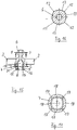
- Figures 11-17 a second embodiment of members 2, which as in Figure 1 of the first exemplary embodiment described above can be assembled to form a line routing device.
- the guide elements 5 extending around the central joint body 5 are rectangular, with two guide elements 3 being connected to one another and formed on the central joint body 5 via a web 10.
- the two webs 10 are arranged in alignment with one another and are integrally formed on the central joint body 5 at radially opposite points.
- the circumferential geometry has four regular corner points 12 which are connected to one another by convexly curved side lines 13 of the same curvature.
- the radius of curvature of the side lines 13 is in turn greater than the radius of the smallest circle surrounding the corner points 12 and the side lines 13.
- the webs 10 connecting the central joint body 5 to the guide elements 3 are integrally formed in the middle area of the outer sides of two opposite sides of the joint socket 7, which in turn are designed as tongues 18, in particular from the Figures 11, 13 and 14 emerges.
Landscapes
- Engineering & Computer Science (AREA)
- Architecture (AREA)
- Civil Engineering (AREA)
- Structural Engineering (AREA)
- General Engineering & Computer Science (AREA)
- Mechanical Engineering (AREA)
- Prostheses (AREA)
- Endoscopes (AREA)
- Harvester Elements (AREA)
- Electric Cable Arrangement Between Relatively Moving Parts (AREA)
- Moulds For Moulding Plastics Or The Like (AREA)
- Pivots And Pivotal Connections (AREA)
Claims (15)
- Dispositif de guidage de lignes (1) comprenant des maillons (2) reliés entre eux de manière articulée, ouverts aux extrémités, disposés les uns derrière les autres dans la direction longitudinale du dispositif de guidage de lignes (1) et formant, au moyen d'éléments de guidage (3) radialement extérieurs, un canal de guidage (4) pour recevoir et guider des lignes d'énergie et/ou des lignes d'information, les maillons (2) présentant chacun, à l'intérieur du canal de guidage (4), un corps d'articulation central (5) pour la liaison articulée de maillons (2) directement voisins qui comprend une tête d'articulation (6) et une cavité articulaire (7) avec une ouverture (8) pour l'insertion de la tête d'articulation (6) d'un maillon (2) immédiatement adjacent, la cavité articulaire (7) ayant une première zone de réception (9) dans lequel la tête d'articulation (6) d'un maillon (2) immédiatement adjacent qui y est insérée est empêchée de tourner autour de l'axe longitudinal (A) du dispositif de guidage de ligne (1), et des maillons (2) immédiatement adjacents pouvant être inclinés dans au moins deux plans angulaires différents par rapport à l'axe longitudinal (A) du dispositif de guidage de ligne (1), caractérisé en ce que la tête d'articulation (6) présente une zone axiale (11) par rapport à l'axe longitudinal (A) du dispositif de guidage de lignes (1), dans laquelle la section transversale de la tête d'articulation (6) présente une géométrie périphérique avec au moins deux points de bord (12) et des lignes latérales (13) reliant ceux-ci entre eux, les lignes latérales (13) se rencontrant en un point d'angle (12) incluant un angle intérieur inférieur à 180° pour tous les points d'angle (12) de la géométrie périphérique, et la cavité articulaire (7) présente une première zone de réception (9) qui correspond géométriquement à la zone axiale (11) de la tête d'articulation (6) et dans laquelle la tête d'articulation (6) peut être engagée, de sorte que la tête d'articulation (6) d'un maillon (2) immédiatement voisin, qui est placée avec la zone axiale (11) dans la première zone de réception (9) de la cavité articulaire (7) d'un maillon (2) peut être disposée là-dedans de manière non rotative et peut être coudée dans au moins deux plans de coude différents.
- Dispositif de guidage de lignes (1) selon la revendication 1 ou 2, caractérisé en ce que les corps d'articulation centraux (5) sont conçus de telle manière que les maillons (2) directement adjacents peuvent être coudés dans tous les plans angulaires qui ont en commun l'axe longitudinal (A) du dispositif de guidage de ligne (1).
- Dispositif de guidage de lignes (1) selon la revendication 1 ou 2, caractérisé en ce que les corps d'articulation centraux (5) sont formés d'une seule pièce, en particulier sont moulés par injection à partir de plastique.
- Dispositif de guidage de lignes (1) selon l'une des revendications 1 à 3, caractérisé en ce que le corps d'articulation (5) d'un maillon (2) présente la tête d'articulation dans sa zone d'extrémité axiale et la cavité articulaire (7) dans son autre zone d'extrémité axiale.
- Dispositif de guidage de lignes (1) selon la revendication 4, caractérisé en ce que l'ouverture (8) de la cavité articulaire (7) pour l'insertion de la tête d'articulation (6) est disposée sur la face frontale axiale (14) du corps d'articulation central (5), laquelle face frontale présente la première zone de réception (9) de la cavité articulaire (7) .
- Dispositif de guidage de lignes (1) selon l'une des revendications 1 à 5, caractérisé en ce que la face intérieure de la zone de bord de l'ouverture (8) présente une géométrie circonférentielle qui est similaire, dans le sens géométrique, à celle de la première zone de réception (9) qui lui est adjacente, elle présentant un rétrécissement (15) par rapport à la première zone de réception (9).
- Dispositif de guidage de lignes (1) selon l'une des revendications 1 à 6, caractérisé en ce que les points de bord de la géométrie circonférentielle de la zone axiale (11) de la tête d'articulation (6) sont régulièrement répartis sur la géométrie circonférentielle.
- Dispositif de guidage de lignes (1) selon l'une des revendications 1 à 7, caractérisé en ce que les lignes latérales (13) reliant les points de bord (12) entre eux sont courbées de façon convexe.
- Dispositif de guidage de lignes (1) selon la revendication 8, caractérisé en ce que toutes les lignes latérales (13) reliant les points de bord (12) entre eux ont le même rayon de courbure.
- Dispositif de guidage de lignes (1) selon la revendication 9, caractérisé en ce que le rayon de courbure des lignes latérales (13) reliant les points de bord (12) entre eux est supérieur au rayon du plus petit cercle entourant les points de bord (12) et les lignes latérales (13), les rayons pouvant notamment être dans un rapport de 5/4-15/4.
- Dispositif de guidage de lignes (1) selon l'une des revendications 1 à 10, caractérisé en ce que la géométrie circonférentielle de la section transversale de la tête d'articulation (6) dans la zone axiale (11) présente au moins trois points de bord (12), en particulier trois ou quatre points de bord (12).
- Dispositif de guidage de lignes (1) selon l'une des revendications 1 à 11, caractérisé en ce que la première zone de réception (9) de la cavité articulaire (7) qui correspond géométriquement à la zone axiale (11) de la tête d'articulation (6) de la cavité articulaire (7) est fendue en direction axiale dans la zone d'au moins une arête d'angle définie par les points de bord (12) de l'ouverture (8).
- Dispositif de guidage de lignes (1) selon l'une des revendications 1 à 12, caractérisé en ce que la cavité articulaire (7) d'un maillon (2) du dispositif de guidage de lignes (1) présente une deuxième zone de réception (19) qui se raccorde à la première zone de réception (9) dans une direction opposée à l'ouverture (8) de la cavité articulaire (7) et dans laquelle la tête d'articulation (6) d'un maillon (2) immédiatement adjacent de la première zone de réception (9) peut être engagée, les deux maillons (2) étant conçus de telle sorte que leur coude relatif l'un par rapport à l'autre est bloqué dans au moins une direction de coude lorsque la tête d'articulation (6) est placée dans la deuxième zone de réception (19) de la cavité articulaire (7).
- Dispositif de guidage de lignes (1) selon la revendication 13, caractérisé en ce que la deuxième zone de réception (19) est séparée de la première zone de réception (9) par une zone de transition (21) dont le diamètre intérieur est inférieur au plus grand diamètre extérieur de l'extrémité de la tête d'articulation (6) et supérieur au diamètre intérieur du rétrécissement (15) sur le côté intérieur de la zone de bord de l'ouverture (8) de la cavité articulaire (7).
- Dispositif de guidage de lignes (1) selon la revendication 13 ou 14, caractérisé en ce que la tête d'articulation (6) présente un col dont le diamètre extérieur est inférieur à celui de la tête d'articulation (6), lequel col est relié à la cavité articulaire (7) par l'intermédiaire d'une zone (20) s'élargissant coniquement, la zone (20) s'élargissant coniquement présentant une géométrie de section transversale similaire au sens géométrique à celle de la première zone de réception (9) de la cavité articulaire (7) et cette géométrie de section transversale correspondant à celle de la zone (16) de l'ouverture (8) de la cavité articulaire (7) qui s'élargit coniquement vers l'extérieur.
Applications Claiming Priority (2)
| Application Number | Priority Date | Filing Date | Title |
|---|---|---|---|
| DE202017101896.2U DE202017101896U1 (de) | 2017-03-31 | 2017-03-31 | Leitungsführungseinrichtung |
| PCT/EP2018/057245 WO2018177862A1 (fr) | 2017-03-31 | 2018-03-22 | Dispositif de guidage de lignes |
Publications (2)
| Publication Number | Publication Date |
|---|---|
| EP3602709A1 EP3602709A1 (fr) | 2020-02-05 |
| EP3602709B1 true EP3602709B1 (fr) | 2021-02-24 |
Family
ID=61868507
Family Applications (1)
| Application Number | Title | Priority Date | Filing Date |
|---|---|---|---|
| EP18714998.4A Active EP3602709B1 (fr) | 2017-03-31 | 2018-03-22 | Dispositif de guidage de lignes |
Country Status (6)
| Country | Link |
|---|---|
| US (1) | US11462893B2 (fr) |
| EP (1) | EP3602709B1 (fr) |
| CN (1) | CN110476311B (fr) |
| DE (1) | DE202017101896U1 (fr) |
| ES (1) | ES2869231T3 (fr) |
| WO (1) | WO2018177862A1 (fr) |
Families Citing this family (8)
| Publication number | Priority date | Publication date | Assignee | Title |
|---|---|---|---|---|
| DE102019207044A1 (de) * | 2019-05-15 | 2020-11-19 | Siemens Healthcare Gmbh | Energieführungskette zur beweglichen Lagerung von zumindest einer flexiblen, insbesondere stromführenden, Leitung, Verwendung der Energieführungskette und bildgebende medizinische Einrichtung |
| US11258242B2 (en) * | 2019-08-13 | 2022-02-22 | BL United, LLC | Modular conduit cable management assembly |
| CN112160979B (zh) * | 2020-09-10 | 2021-12-17 | 北京交通大学 | 一种u副铰链 |
| CN112260174A (zh) * | 2020-10-31 | 2021-01-22 | 江苏科瑞斯机件有限公司 | 快速拆装穿线导链 |
| CN112952727B (zh) * | 2021-02-07 | 2022-09-09 | 中国科学院合肥物质科学研究院 | 一种大容量旋转拖链 |
| DE202021100995U1 (de) * | 2021-02-26 | 2022-05-30 | Igus Gmbh | Räumlich auslenkbare Leitungsführungseinrichtung, insbesondere für einen Roboter |
| CN113595019B (zh) * | 2021-06-16 | 2023-03-28 | 平高集团有限公司 | 一种软导线端部固定金具 |
| PL442460A1 (pl) * | 2022-10-06 | 2024-04-08 | Splast Spółka Z Ograniczoną Odpowiedzialnością | Prowadnica kabli |
Family Cites Families (15)
| Publication number | Priority date | Publication date | Assignee | Title |
|---|---|---|---|---|
| IT208046Z2 (it) * | 1986-09-15 | 1988-03-31 | Tecno Mobili E Forniture Per A | Organo passocavo flessibile a snodi bidirezionali. |
| US5824957A (en) * | 1991-09-03 | 1998-10-20 | Technology Finance Corporation (Proprietary) Limited | Electrical cable containment |
| WO1996035887A1 (fr) | 1995-05-10 | 1996-11-14 | Ernst Moeckl | Chaine-cable |
| IT1317520B1 (it) | 2000-05-11 | 2003-07-09 | Traversa Ezio Plastici | Elementi componibili ed orientabili per canaline passacavi. |
| IT1318950B1 (it) * | 2000-10-02 | 2003-09-19 | Gianfranchi Pier Luigi | Canale componibile per il confinamento di cavi elettrici e simili. |
| DE20305487U1 (de) | 2003-04-03 | 2003-06-12 | Igus Spritzgußteile für die Industrie GmbH, 51147 Köln | Kabelführung |
| DE20305680U1 (de) * | 2003-04-07 | 2003-07-17 | Igus Spritzgußteile für die Industrie GmbH, 51147 Köln | Kabelführung |
| DE20317827U1 (de) * | 2003-11-18 | 2005-03-31 | Ruettiger Maximilian | Koppelbares Kettenglied einer Leitungsführungskette |
| DE102007017940A1 (de) | 2007-04-13 | 2008-10-16 | Igus Gmbh | Seitenwandsegment für eine Leitungsführungseinrichtung, Leitungsführungseinrichtung mit Seitenwandsegment und Verfahren zur Herstellung des Seitenwandsegmentes |
| DE202009005650U1 (de) | 2009-04-17 | 2009-07-02 | Igus Gmbh | Energieführungskette |
| DE102010032920C5 (de) * | 2010-07-30 | 2023-03-02 | Tsubaki Kabelschlepp GmbH | Räumlich auslenkbare Leitungsführungseinrichtung mit Krümmungsradiusbegrenzern |
| CN204793903U (zh) * | 2015-07-15 | 2015-11-18 | 季德贵 | 可过线铰链 |
| US10444459B2 (en) * | 2015-10-19 | 2019-10-15 | Commscope Technologies Llc | Articulating optical fiber guide system |
| CN205533751U (zh) | 2016-01-15 | 2016-08-31 | 济南思漫设备科技有限公司 | 一种可容纳电缆的球形铰链 |
| EP3402026B1 (fr) * | 2017-05-11 | 2020-07-08 | HellermannTyton GmbH | Ensemble constitué de modules de canal de câble assemblés |
-
2017
- 2017-03-31 DE DE202017101896.2U patent/DE202017101896U1/de active Active
-
2018
- 2018-03-22 ES ES18714998T patent/ES2869231T3/es active Active
- 2018-03-22 WO PCT/EP2018/057245 patent/WO2018177862A1/fr active Application Filing
- 2018-03-22 CN CN201880023444.3A patent/CN110476311B/zh active Active
- 2018-03-22 EP EP18714998.4A patent/EP3602709B1/fr active Active
- 2018-03-22 US US16/499,519 patent/US11462893B2/en active Active
Non-Patent Citations (1)
| Title |
|---|
| None * |
Also Published As
| Publication number | Publication date |
|---|---|
| WO2018177862A1 (fr) | 2018-10-04 |
| DE202017101896U1 (de) | 2018-07-04 |
| CN110476311A (zh) | 2019-11-19 |
| EP3602709A1 (fr) | 2020-02-05 |
| US20200044425A1 (en) | 2020-02-06 |
| ES2869231T3 (es) | 2021-10-25 |
| CN110476311B (zh) | 2021-01-05 |
| US11462893B2 (en) | 2022-10-04 |
Similar Documents
| Publication | Publication Date | Title |
|---|---|---|
| EP3602709B1 (fr) | Dispositif de guidage de lignes | |
| EP0599784B1 (fr) | Douille pour un terminal de connexion à fibre optique | |
| EP2694841B1 (fr) | Chaîne porte-câbles comportant des éléments d'articulation déformables | |
| EP1969279B1 (fr) | Piece de couplage pour systeme de connecteur enfichable | |
| DE19710489A1 (de) | Faltbares Schutzelement für Leitungen | |
| EP1977677A1 (fr) | Instrument endoscopique | |
| DE2941008B1 (de) | Gestell | |
| EP3096025A1 (fr) | Couplage comprenant des tiges de couplage et dispositifs de retenue et procede de liaison d'un premier et d'un second composant a l'aide du couplage | |
| DE102015110162B4 (de) | Energieführungskette umfassend ein zwischen den Gliedern eingefügtes separates Federelement, das die benachbarten Glieder in eine Vorzugsausrichtung vorspannt | |
| DE202012001760U1 (de) | Kabelführung | |
| EP1559605B1 (fr) | Dispositif antiperte pour bouchon de réceptacle | |
| EP3445997B1 (fr) | Pièce latérale, maillon de chaîne et chaîne porte-câbles | |
| EP3253993B1 (fr) | Maillon de chaîne et chaîne circulaire munie de maillons | |
| DE19911724C1 (de) | Wellrohrverbindung mit Sperrabschnitt | |
| EP4158223B1 (fr) | Chaîne porte-câbles à éléments de raccordement articulés flexibles, ainsi que pattes latérales et élément de raccordement articulé approprié | |
| DE20305680U1 (de) | Kabelführung | |
| DE202017105244U1 (de) | Energieführungskette mit in die Gelenkverbindungen integrierten Schwenkwinkel-Anschlägen und entsprechende Kettenlaschen | |
| EP1416109B1 (fr) | Dispositif d'actionnement pour une serrure de porte ou d'ouvrant de véhicule | |
| EP3563009B1 (fr) | Dispositif de fixation de paravents servant à la fixation articulée de paravents et système de paravent | |
| EP2905799B1 (fr) | Système constitué d'un appareil de base et d'un élément auxiliaire | |
| DE3001195A1 (de) | Schnappvorrichtung zur loesbaren verbindung von zwei teilen oder brettern | |
| DE202022103613U1 (de) | Installationsgerät zur Installation einer Schalteinrichtung | |
| DE3734595C2 (fr) | ||
| DE202021101933U1 (de) | Energieführungskette mit biegsamen Gelenkverbindern, sowie Seitenlaschen und Gelenkverbinder hierfür | |
| DE60032865T2 (de) | Steuereinrichtung für kraftfahrzeugausrüstung |
Legal Events
| Date | Code | Title | Description |
|---|---|---|---|
| STAA | Information on the status of an ep patent application or granted ep patent |
Free format text: STATUS: UNKNOWN |
|
| STAA | Information on the status of an ep patent application or granted ep patent |
Free format text: STATUS: THE INTERNATIONAL PUBLICATION HAS BEEN MADE |
|
| PUAI | Public reference made under article 153(3) epc to a published international application that has entered the european phase |
Free format text: ORIGINAL CODE: 0009012 |
|
| STAA | Information on the status of an ep patent application or granted ep patent |
Free format text: STATUS: REQUEST FOR EXAMINATION WAS MADE |
|
| 17P | Request for examination filed |
Effective date: 20190830 |
|
| AK | Designated contracting states |
Kind code of ref document: A1 Designated state(s): AL AT BE BG CH CY CZ DE DK EE ES FI FR GB GR HR HU IE IS IT LI LT LU LV MC MK MT NL NO PL PT RO RS SE SI SK SM TR |
|
| AX | Request for extension of the european patent |
Extension state: BA ME |
|
| DAV | Request for validation of the european patent (deleted) | ||
| DAX | Request for extension of the european patent (deleted) | ||
| RIC1 | Information provided on ipc code assigned before grant |
Ipc: H02G 11/00 20060101ALN20200803BHEP Ipc: F16G 13/16 20060101ALI20200803BHEP Ipc: H02G 3/04 20060101AFI20200803BHEP |
|
| GRAP | Despatch of communication of intention to grant a patent |
Free format text: ORIGINAL CODE: EPIDOSNIGR1 |
|
| STAA | Information on the status of an ep patent application or granted ep patent |
Free format text: STATUS: GRANT OF PATENT IS INTENDED |
|
| INTG | Intention to grant announced |
Effective date: 20200914 |
|
| GRAS | Grant fee paid |
Free format text: ORIGINAL CODE: EPIDOSNIGR3 |
|
| GRAA | (expected) grant |
Free format text: ORIGINAL CODE: 0009210 |
|
| STAA | Information on the status of an ep patent application or granted ep patent |
Free format text: STATUS: THE PATENT HAS BEEN GRANTED |
|
| AK | Designated contracting states |
Kind code of ref document: B1 Designated state(s): AL AT BE BG CH CY CZ DE DK EE ES FI FR GB GR HR HU IE IS IT LI LT LU LV MC MK MT NL NO PL PT RO RS SE SI SK SM TR |
|
| REG | Reference to a national code |
Ref country code: CH Ref legal event code: EP |
|
| REG | Reference to a national code |
Ref country code: DE Ref legal event code: R096 Ref document number: 502018004034 Country of ref document: DE |
|
| REG | Reference to a national code |
Ref country code: AT Ref legal event code: REF Ref document number: 1365686 Country of ref document: AT Kind code of ref document: T Effective date: 20210315 |
|
| REG | Reference to a national code |
Ref country code: IE Ref legal event code: FG4D Free format text: LANGUAGE OF EP DOCUMENT: GERMAN |
|
| REG | Reference to a national code |
Ref country code: CH Ref legal event code: NV Representative=s name: KATZAROV SA, CH |
|
| REG | Reference to a national code |
Ref country code: LT Ref legal event code: MG9D |
|
| REG | Reference to a national code |
Ref country code: NL Ref legal event code: MP Effective date: 20210224 |
|
| PG25 | Lapsed in a contracting state [announced via postgrant information from national office to epo] |
Ref country code: BG Free format text: LAPSE BECAUSE OF FAILURE TO SUBMIT A TRANSLATION OF THE DESCRIPTION OR TO PAY THE FEE WITHIN THE PRESCRIBED TIME-LIMIT Effective date: 20210524 Ref country code: HR Free format text: LAPSE BECAUSE OF FAILURE TO SUBMIT A TRANSLATION OF THE DESCRIPTION OR TO PAY THE FEE WITHIN THE PRESCRIBED TIME-LIMIT Effective date: 20210224 Ref country code: GR Free format text: LAPSE BECAUSE OF FAILURE TO SUBMIT A TRANSLATION OF THE DESCRIPTION OR TO PAY THE FEE WITHIN THE PRESCRIBED TIME-LIMIT Effective date: 20210525 Ref country code: FI Free format text: LAPSE BECAUSE OF FAILURE TO SUBMIT A TRANSLATION OF THE DESCRIPTION OR TO PAY THE FEE WITHIN THE PRESCRIBED TIME-LIMIT Effective date: 20210224 Ref country code: NO Free format text: LAPSE BECAUSE OF FAILURE TO SUBMIT A TRANSLATION OF THE DESCRIPTION OR TO PAY THE FEE WITHIN THE PRESCRIBED TIME-LIMIT Effective date: 20210524 Ref country code: PT Free format text: LAPSE BECAUSE OF FAILURE TO SUBMIT A TRANSLATION OF THE DESCRIPTION OR TO PAY THE FEE WITHIN THE PRESCRIBED TIME-LIMIT Effective date: 20210624 Ref country code: LT Free format text: LAPSE BECAUSE OF FAILURE TO SUBMIT A TRANSLATION OF THE DESCRIPTION OR TO PAY THE FEE WITHIN THE PRESCRIBED TIME-LIMIT Effective date: 20210224 |
|
| PG25 | Lapsed in a contracting state [announced via postgrant information from national office to epo] |
Ref country code: SE Free format text: LAPSE BECAUSE OF FAILURE TO SUBMIT A TRANSLATION OF THE DESCRIPTION OR TO PAY THE FEE WITHIN THE PRESCRIBED TIME-LIMIT Effective date: 20210224 Ref country code: RS Free format text: LAPSE BECAUSE OF FAILURE TO SUBMIT A TRANSLATION OF THE DESCRIPTION OR TO PAY THE FEE WITHIN THE PRESCRIBED TIME-LIMIT Effective date: 20210224 Ref country code: LV Free format text: LAPSE BECAUSE OF FAILURE TO SUBMIT A TRANSLATION OF THE DESCRIPTION OR TO PAY THE FEE WITHIN THE PRESCRIBED TIME-LIMIT Effective date: 20210224 Ref country code: NL Free format text: LAPSE BECAUSE OF FAILURE TO SUBMIT A TRANSLATION OF THE DESCRIPTION OR TO PAY THE FEE WITHIN THE PRESCRIBED TIME-LIMIT Effective date: 20210224 Ref country code: PL Free format text: LAPSE BECAUSE OF FAILURE TO SUBMIT A TRANSLATION OF THE DESCRIPTION OR TO PAY THE FEE WITHIN THE PRESCRIBED TIME-LIMIT Effective date: 20210224 |
|
| PG25 | Lapsed in a contracting state [announced via postgrant information from national office to epo] |
Ref country code: IS Free format text: LAPSE BECAUSE OF FAILURE TO SUBMIT A TRANSLATION OF THE DESCRIPTION OR TO PAY THE FEE WITHIN THE PRESCRIBED TIME-LIMIT Effective date: 20210624 |
|
| REG | Reference to a national code |
Ref country code: ES Ref legal event code: FG2A Ref document number: 2869231 Country of ref document: ES Kind code of ref document: T3 Effective date: 20211025 |
|
| PG25 | Lapsed in a contracting state [announced via postgrant information from national office to epo] |
Ref country code: EE Free format text: LAPSE BECAUSE OF FAILURE TO SUBMIT A TRANSLATION OF THE DESCRIPTION OR TO PAY THE FEE WITHIN THE PRESCRIBED TIME-LIMIT Effective date: 20210224 Ref country code: SM Free format text: LAPSE BECAUSE OF FAILURE TO SUBMIT A TRANSLATION OF THE DESCRIPTION OR TO PAY THE FEE WITHIN THE PRESCRIBED TIME-LIMIT Effective date: 20210224 |
|
| REG | Reference to a national code |
Ref country code: DE Ref legal event code: R097 Ref document number: 502018004034 Country of ref document: DE |
|
| PG25 | Lapsed in a contracting state [announced via postgrant information from national office to epo] |
Ref country code: DK Free format text: LAPSE BECAUSE OF FAILURE TO SUBMIT A TRANSLATION OF THE DESCRIPTION OR TO PAY THE FEE WITHIN THE PRESCRIBED TIME-LIMIT Effective date: 20210224 Ref country code: SK Free format text: LAPSE BECAUSE OF FAILURE TO SUBMIT A TRANSLATION OF THE DESCRIPTION OR TO PAY THE FEE WITHIN THE PRESCRIBED TIME-LIMIT Effective date: 20210224 Ref country code: RO Free format text: LAPSE BECAUSE OF FAILURE TO SUBMIT A TRANSLATION OF THE DESCRIPTION OR TO PAY THE FEE WITHIN THE PRESCRIBED TIME-LIMIT Effective date: 20210224 Ref country code: MC Free format text: LAPSE BECAUSE OF FAILURE TO SUBMIT A TRANSLATION OF THE DESCRIPTION OR TO PAY THE FEE WITHIN THE PRESCRIBED TIME-LIMIT Effective date: 20210224 |
|
| REG | Reference to a national code |
Ref country code: BE Ref legal event code: MM Effective date: 20210331 |
|
| PLBE | No opposition filed within time limit |
Free format text: ORIGINAL CODE: 0009261 |
|
| STAA | Information on the status of an ep patent application or granted ep patent |
Free format text: STATUS: NO OPPOSITION FILED WITHIN TIME LIMIT |
|
| PG25 | Lapsed in a contracting state [announced via postgrant information from national office to epo] |
Ref country code: IE Free format text: LAPSE BECAUSE OF NON-PAYMENT OF DUE FEES Effective date: 20210322 Ref country code: LU Free format text: LAPSE BECAUSE OF NON-PAYMENT OF DUE FEES Effective date: 20210322 Ref country code: AL Free format text: LAPSE BECAUSE OF FAILURE TO SUBMIT A TRANSLATION OF THE DESCRIPTION OR TO PAY THE FEE WITHIN THE PRESCRIBED TIME-LIMIT Effective date: 20210224 |
|
| 26N | No opposition filed |
Effective date: 20211125 |
|
| PG25 | Lapsed in a contracting state [announced via postgrant information from national office to epo] |
Ref country code: SI Free format text: LAPSE BECAUSE OF FAILURE TO SUBMIT A TRANSLATION OF THE DESCRIPTION OR TO PAY THE FEE WITHIN THE PRESCRIBED TIME-LIMIT Effective date: 20210224 |
|
| PG25 | Lapsed in a contracting state [announced via postgrant information from national office to epo] |
Ref country code: IS Free format text: LAPSE BECAUSE OF FAILURE TO SUBMIT A TRANSLATION OF THE DESCRIPTION OR TO PAY THE FEE WITHIN THE PRESCRIBED TIME-LIMIT Effective date: 20210624 |
|
| PG25 | Lapsed in a contracting state [announced via postgrant information from national office to epo] |
Ref country code: BE Free format text: LAPSE BECAUSE OF NON-PAYMENT OF DUE FEES Effective date: 20210331 |
|
| PG25 | Lapsed in a contracting state [announced via postgrant information from national office to epo] |
Ref country code: CY Free format text: LAPSE BECAUSE OF FAILURE TO SUBMIT A TRANSLATION OF THE DESCRIPTION OR TO PAY THE FEE WITHIN THE PRESCRIBED TIME-LIMIT Effective date: 20210224 |
|
| P01 | Opt-out of the competence of the unified patent court (upc) registered |
Effective date: 20230526 |
|
| PG25 | Lapsed in a contracting state [announced via postgrant information from national office to epo] |
Ref country code: HU Free format text: LAPSE BECAUSE OF FAILURE TO SUBMIT A TRANSLATION OF THE DESCRIPTION OR TO PAY THE FEE WITHIN THE PRESCRIBED TIME-LIMIT; INVALID AB INITIO Effective date: 20180322 |
|
| PGFP | Annual fee paid to national office [announced via postgrant information from national office to epo] |
Ref country code: AT Payment date: 20240318 Year of fee payment: 7 |
|
| PG25 | Lapsed in a contracting state [announced via postgrant information from national office to epo] |
Ref country code: MK Free format text: LAPSE BECAUSE OF FAILURE TO SUBMIT A TRANSLATION OF THE DESCRIPTION OR TO PAY THE FEE WITHIN THE PRESCRIBED TIME-LIMIT Effective date: 20210224 |
|
| PGFP | Annual fee paid to national office [announced via postgrant information from national office to epo] |
Ref country code: CZ Payment date: 20240308 Year of fee payment: 7 Ref country code: GB Payment date: 20240322 Year of fee payment: 7 |
|
| PGFP | Annual fee paid to national office [announced via postgrant information from national office to epo] |
Ref country code: IT Payment date: 20240329 Year of fee payment: 7 Ref country code: FR Payment date: 20240320 Year of fee payment: 7 |
|
| PGFP | Annual fee paid to national office [announced via postgrant information from national office to epo] |
Ref country code: DE Payment date: 20240527 Year of fee payment: 7 |
|
| PGFP | Annual fee paid to national office [announced via postgrant information from national office to epo] |
Ref country code: CH Payment date: 20240401 Year of fee payment: 7 |
|
| PGFP | Annual fee paid to national office [announced via postgrant information from national office to epo] |
Ref country code: ES Payment date: 20240417 Year of fee payment: 7 |
|
| PG25 | Lapsed in a contracting state [announced via postgrant information from national office to epo] |
Ref country code: MT Free format text: LAPSE BECAUSE OF FAILURE TO SUBMIT A TRANSLATION OF THE DESCRIPTION OR TO PAY THE FEE WITHIN THE PRESCRIBED TIME-LIMIT Effective date: 20210224 |