EP3601702B1 - Bodenplatte zur formung eines bodenbelags - Google Patents
Bodenplatte zur formung eines bodenbelags Download PDFInfo
- Publication number
- EP3601702B1 EP3601702B1 EP18720002.7A EP18720002A EP3601702B1 EP 3601702 B1 EP3601702 B1 EP 3601702B1 EP 18720002 A EP18720002 A EP 18720002A EP 3601702 B1 EP3601702 B1 EP 3601702B1
- Authority
- EP
- European Patent Office
- Prior art keywords
- floor panel
- edges
- locking
- floor
- coupling parts
- Prior art date
- Legal status (The legal status is an assumption and is not a legal conclusion. Google has not performed a legal analysis and makes no representation as to the accuracy of the status listed.)
- Active
Links
Images

Classifications
-
- E—FIXED CONSTRUCTIONS
- E04—BUILDING
- E04F—FINISHING WORK ON BUILDINGS, e.g. STAIRS, FLOORS
- E04F15/00—Flooring
- E04F15/02—Flooring or floor layers composed of a number of similar elements
-
- E—FIXED CONSTRUCTIONS
- E04—BUILDING
- E04F—FINISHING WORK ON BUILDINGS, e.g. STAIRS, FLOORS
- E04F15/00—Flooring
- E04F15/02—Flooring or floor layers composed of a number of similar elements
- E04F15/02038—Flooring or floor layers composed of a number of similar elements characterised by tongue and groove connections between neighbouring flooring elements
-
- E—FIXED CONSTRUCTIONS
- E04—BUILDING
- E04F—FINISHING WORK ON BUILDINGS, e.g. STAIRS, FLOORS
- E04F15/00—Flooring
- E04F15/02—Flooring or floor layers composed of a number of similar elements
- E04F15/10—Flooring or floor layers composed of a number of similar elements of other materials, e.g. fibrous or chipped materials, organic plastics, magnesite tiles, hardboard, or with a top layer of other materials
- E04F15/107—Flooring or floor layers composed of a number of similar elements of other materials, e.g. fibrous or chipped materials, organic plastics, magnesite tiles, hardboard, or with a top layer of other materials composed of several layers, e.g. sandwich panels
-
- E—FIXED CONSTRUCTIONS
- E04—BUILDING
- E04F—FINISHING WORK ON BUILDINGS, e.g. STAIRS, FLOORS
- E04F2201/00—Joining sheets or plates or panels
- E04F2201/01—Joining sheets, plates or panels with edges in abutting relationship
- E04F2201/0138—Joining sheets, plates or panels with edges in abutting relationship by moving the sheets, plates or panels perpendicular to the main plane
-
- E—FIXED CONSTRUCTIONS
- E04—BUILDING
- E04F—FINISHING WORK ON BUILDINGS, e.g. STAIRS, FLOORS
- E04F2201/00—Joining sheets or plates or panels
- E04F2201/01—Joining sheets, plates or panels with edges in abutting relationship
- E04F2201/0153—Joining sheets, plates or panels with edges in abutting relationship by rotating the sheets, plates or panels around an axis which is parallel to the abutting edges, possibly combined with a sliding movement
Definitions
- This invention relates to a floor panel for forming a floor covering, more particularly for forming a floor covering which can be installed on an underlying surface.
- the invention relates to floor panels which can be coupled to each other by means of mechanical coupling parts.
- the aim of the invention consists in that a floor covering of such floor panels is easy to install, however, that at the same time still sufficient strength is obtained in the floor covering, more particularly sufficiently strong connections can be realized between the floor panels, such in combination with production techniques which keep the production costs of the floor panels limited.
- the invention aims at floor panels which can be installed by means of so-called fold-down technique, such in order to be able to fulfill the aimed-at requirement of a simple installation.
- a fact hereby is that it must be possible to join two of the edges, mostly the short edges in the case of oblong floor panels, into each other by means of a downward movement, wherein then a vertical locking must be achieved.
- vertical locking can be realized with separate elastic locking strips.
- realizing and applying those is costly. In order to exclude this cost, one-piece or substantially one-piece coupling profiles can be applied.
- the invention aims at a similar coupling as described in PCT/IB2016/057706, however, provides for a number of changes which result in an improved coupling. In general, thereby the coupling is better, however, more specifically it is well usable for being made in one piece in MDF or HDF.
- the invention provides for a floor panel as defined in claim 1.
- Preferred embodiments are defined in the dependent claims.
- the present invention relates to a floor panel for forming a floor covering
- the following characteristics or a combination, of two, three, four, five or all six of the following characteristics (I)-(VI) may be present:
- the invention is primary suitable for floor panels wherein the coupling parts of the second pair of edges are made in one piece in MDF (Medium Density Fiberboard) or HDF (High Density Fiberboard).
- MDF Medium Density Fiberboard
- HDF High Density Fiberboard
- the aforementioned characteristics I to VII allow an optimum integration of such coupling parts in MDF or HDF.
- this will relate to floor panels comprising a substrate of MDF or HDF extending over the entire or approximately entire surface thereof, wherein at the edges the aforementioned coupling parts are formed.
- the floor panel preferably comprises a decorative top layer.
- this top layer consists of DPL (Direct Pressure Laminate), HPL (High Pressure Laminate), wood veneer, a layer of solid wood, linoleum, cork, one or more printing layers, one or more lacquer layers or a synthetic material layer, such as, for example, vinyl, or a combination of two or more of such layers.
- DPL Direct Pressure Laminate
- HPL High Pressure Laminate
- wood veneer a layer of solid wood, linoleum, cork, one or more printing layers, one or more lacquer layers or a synthetic material layer, such as, for example, vinyl, or a combination of two or more of such layers.
- the invention primarily is suitable for being applied in floor panels wherein the coupling parts of at least the second pair of edges are realized in MDF/HDF material, more particularly in the MDF/HDF material of the substrate, does not exclude that it is also advantageous in floor panels of other materials.
- floor panels which are characterized in that they comprise a, whether or not multi-layered, synthetic material-based substrate, wherein the coupling parts of at least the second pair of edges, and preferably of the first pair of edges, too, are manufactured in one piece of the panel material, and more particularly the material of the substrate, and wherein this floor panel preferably comprises a decorative top layer.
- this is a so-called LVT floor panel, either of the "resilient” type or of the "rigid” type; or that it is a comparable floor panel on the basis of another synthetic material than vinyl, for example, polyurethane; or that it is a synthetic material-based floor panel with a substrate that is composed of at least two layers, more particularly with a substrate layer which is realized of foamed and possibly filled synthetic material and which preferably has a thickness which is larger than half of the overall thickness of the floor panel, and a not or less foamed synthetic material layer, which is provided above the substrate layer and has a thickness of at least 1 mm, for example, a vinyl layer, on which then preferably a decorative top layer is present.
- one or more reinforcement layers for example, glass fiber layers
- one or more reinforcement layers can be present.
- a variety of fillers and additives may be present in the applied synthetic materials.
- the fillers may or may not be more than 50 percent by weight of the total weight of the respective material.
- the floor panel shows the characteristic that the aforementioned lower hook-shaped part, at the distal side of its distal end, is free from mechanical vertically active locking parts. More particularly, herein it is recommended that in the coupled condition a space is present behind the distal end of the lower hook-shaped part. Preferably this means that only in the first and the second contact zone vertically active locking parts are present, thus, on only two locations which are situated opposite to each other.
- the advantage hereof is that tolerance differences, more particularly production tolerances, can be absorbed more smoothly and thus are less critical in the production of the floor panels.
- the floor panel shows the characteristic that the aforementioned lower hook-shaped part, at the distal side of its distal end, indeed is provided with one or more mechanical vertically active locking parts, which then cooperate(s) with a locking part, provided for this purpose, of an adjoining floor panel.
- a disadvantage therein then is that the allowable production tolerances are more critical, however, contrary thereto then there is the advantage that a vertical locking is obtained at three locations, namely in the first contact zone, in the second contact zone and at the distal end of the respective hook-shaped part.
- the floor panel according to the invention is characterized in that the two contact surfaces of the second contact zone, including possible prolongations thereof, seen in cross-section extend both to the left and to the right of the respective closing plane, wherein the closing plane is defined as a vertical plane through the upper edges of the coupled floor panels or at least the location where the floor panels come together at the top.
- the floor panel of the invention is characterized in that at the lower side of the lip of the lower hook-shaped part, a recess extending up to the distal end of the lip is present, said recess allowing a downward bending of the lip, or anyhow of at least a portion thereof, wherein preferably the recess is configured such that the aforementioned downward bending substantially provides for a tilting movement of the upward-directed locking element, wherein thereby, in the portion of the lip situated directly proximal to the upward-directed locking element, no or little downward bending will occur, or at least to a lesser extent then the portion carrying the locking element.
- the floor panel is characterized in that, at the lower edges of the male part, guiding surfaces, such as chamfers or roundings, are present, which are configured such that the male part, during the downward movement thereof, automatically is guided into the female part, at which the necessary guiding surfaces can be present, too, and that the male part therein always is becoming seated with at least the lower portion in the female part before an apart-pressing force is created as a result of the locking parts, which belong to the second contact zone, initially moving along each other.
- guiding surfaces such as chamfers or roundings
- the tangent line in the first contact zone forms an angle with the horizontal of at least 75 degrees, and still better is at least 80 degrees, and preferably in the order of magnitude of 85 degrees or more.
- the tangent line in the second contact zone preferably forms an angle with the horizontal of less than 50 degrees, and still better less than 45 degrees, and still better less than 30 degrees, all of this preferably in combination with the angle values for the tangent line of the first contact zone described in the preceding paragraph.
- the coupling parts at the second pair of edges are configured such that they, in coupled condition, create a so-called pretension.
- the floor panel of the invention is characterized in that the upward-directed locking element, the downward-directed locking element and the pertaining contact surfaces of the first contact zone are configured such that the upward-directed locking element with its pertaining contact surface, in the coupled condition, adopts a somewhat tilted position in respect to the position which is taken by this contact surface in the free condition; and that both contact surfaces of the first contact zone, in the not coupled condition, mutually are oriented so deviating that, in the coupled condition, mutually a less deviating or not deviating orientation is obtained.
- the contact surfaces of the first contact zone, in the coupled condition coincide with each other or almost coincide with each other.
- the aforementioned contact surfaces when for their free condition the contours thereof are presented on top of each other, converge towards each other or, in other words, provide for a diminishing overlap in downward direction. Still more particularly, herein it preferred that the aforementioned contact surfaces are substantially flat and that, when for their free condition the contours of the coupling parts are presented on top of each other, the respective contact surfaces show an angular difference of 2 to 10 degrees.
- the latter is characterized in that it further comprises, if not already mentioned, one or more of the following features, or comprises any combination of these features among each other and/or in combination with any of the features of the previously described characteristics, this as far as such combination does not comprise any contradictory features:
- the invention in general preferably relates to decorative floor panels for a floor covering which is to be installed floatingly.
- the invention can also be applied with panels for forming a subfloor.
- a floating support point means that overlapping tolerances are avoided and/or a theoretical space is used in the profile shapes which is very small, preferably is less than 0.2 mm and still better less than 0.1 mm, and preferably a desired value in the order of magnitude of 0.05 mm.
- the floating support point facilitates joining, however, under load still offers sufficient support without too many height differences.
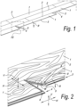
- the invention relates to floor panels 1 for forming a floor covering, which floor panels 1 comprise a first pair of opposite edges 2-3 and a second pair of opposite edges 4-5.
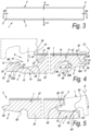
- the represented floor panels 1 are figured such at their edges that they are mutually coupleable according to the so-called fold-down principle, which is a principle known as such and which consists in that such floor panels 1 can be coupled to each other at the first pair of edges 2-3 by a turning movement R and at the second pair of edges 4-5 can be coupled to each other by a downward movement M, wherein the downward movement M is the result of the turning movement R and thus is effected substantially simultaneously.
- the floor panels 1 also are configured such at their edges 2-3 and 4-5 that finally a locking is effected in vertical direction V as well as in horizontal direction H, this latter perpendicular to the respective edges.
- the coupling parts 6-7 of the first pair of edges 2-3 show at least the following basic characteristics:
- the coupling parts 8-9 of the second pair of opposite edges 4-5 show at least the following basic characteristics:
- characteristic VII is applied and further one of the herein below defined characteristics I to VI may be applied or a combination of two, three, four, five or all six of these characteristics I to VI may be present.
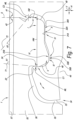
- the locations of the characteristics I to VI are indicated specifically in figure 7 by references I to VI, whereas the location of characteristic VII is indicated specifically in figure 9 by reference VII.
- this relates to the following characteristics:
- the ratio between the horizontal distance HM and the vertical distance VM between the middles of the contact zones has to meet a requirement.
- the middles are indicated by marking lines ML. That the ratio HM/VM is greater than 5 and still better is greater than 6 implies that the male part 17 manifests itself relatively longitudinally extended in horizontal direction compared to the global shape of the coupling, that the height difference VM remains relatively small and that the lip 12 of the lower hook-shaped part 10, in relation to the global shape of the coupling, also is relatively long, considering that the length thereof is also determined by the distance HM.
- the aforementioned ratio provides for that the upward-directed locking part 13 can bend in a relatively smooth manner, even with relatively rigid material, such as MDF or HDF, and the male part 17 can be snapped home in the female part by means of a downward snap movement.
- relatively small height VM provides for that, with a horizontal traction force, the torque remains small and the coupling therein still offers sufficient resistance against undesired turning open as a result of bending.
- this support point is provided which is active in downward direction, in other words, limits the movement of the male part 17 in downward direction, wherein this support point according to the invention is realized as a floating support point.
- this support point relates to the support point 32A formed by contact surfaces 30A and 31A.
- Such floating support point provides for that the male part, at the location of this support point, can be pressed downward with certainty up to the entire depth or even can be pressed somewhat further downward.
- This has the advantage that the male part 17, amongst others, at the height of the second contact zone C2, can be smoothly brought with its respective locking part 19 up to underneath the respective locking part 21 of the female part 14 by exerting an additional downward force.
- the snap effect is facilitated, while still a support point 32A is offered, which, with a large downward load on the floor panel, offers the necessary support at the location of the male part 17.
- a downwardly active support point 32B is provided, which is situated in the proximal half or substantially in the proximal half of the male part 17, in other words, in figure 7 in the left half of the male part 17, while at the distal half of the male part 17, no downwardly active support point or only a floating downwardly active support point 32A is present at the lower side of the male part 17.
- a particularly rigid support in the distal half is excluded, by which the first-mentioned support point 32B then unhampered can be configured as a support point in an optimum manner.
- the first-mentioned support point is situated in the proximity of the end of the lip 12 of the lower hook-shaped part 10, an elastic support can be provided.
- two support points are present at the lower side of the male part 17, wherein the support point, which is most proximal in respect to the male part 17, is situated lower than the other of the two support points.
- one or both of the support points may or may not be realized as floating support points.
- the fact that the most proximal support point of the male part is situated lower, implies that the lip of the lower hook-shaped part becomes thinner and thus more flexible towards its distal end, which allows a smooth joining.
- support point means a location where there is contact or can be made. This can be a local point, as well as a zone extending in the cross-section of the respective edge over a distance.
- the male part 17, next to the proximal half thereof extends deeper than next to the distal half thereof, this independently from the fact whether there are support points in downward direction or not.
- This characteristic implies that the lip 12 of the lower hook-shaped part becomes thinner and thus more flexible towards its distal end, which allows a smooth joining.
- the possibility is created of working with a larger engagement height between the lower hook-shaped part 10 and the upper hook-shaped part 11.
- the horizontal distance HM between the middle of the first contact zone C1 and the second contact zone C2 is at least 3 mm.
- This comparatively large distance implies that the lower hook-shaped part 10 is relatively long, too.
- the inventor has found that such minimal horizontal distance offers good results primarily with coupling parts which are realized from MDF or HDF, more particularly in one piece from an MDF substrate or HDF substrate. It was found that the coupling parts then can be smoothly snapped into each other by a downward movement, while still sufficient vertical locking is obtained. Also, by this length the risk is reduced that the male part breaks off due to sliding off in the MDF or HDF.
- the incision 14A of the invention offers the advantage that the lip of the lower hook-shaped part 10 as such becomes comparatively long and flexible, while the horizontal distance HM between the middles of the contact zones C1 and C2 is less dependent thereon.
- the floor panel 1 preferably is composed of a substrate, in the example indicated by reference 52, and at least a decorative top layer 52. Further, at the lower side a not-represented counter layer or balancing layer can be provided, which can have the purpose of preventing the warping of the floor panel.
- the coupling parts preferably are made in one piece from the panel material, and more particularly from the material of the substrate 52, which preferably is valid for the coupling parts 6-7 of the first pair of edges 2-3 as well as for the coupling parts 8-9 of the second pair of edges 4-5.
- the substrate 52 as such can be made monolithic, thus, consisting of a single board of a certain material, as well as can be composed of different layers and/or parts.
- the substrate 52 consists of a single board, for example, of MDF (Medium Density Fiberboard) or HDF (High Density Fiberboard).
- the decorative top layer 57 can consist of any material. A number of examples are described in the introduction.
- the top layer preferably consists of DPL (Direct Pressure Laminate), which, as known, mostly consists of a number of resinated paper layers, which are pressed on the substrate and consolidated, amongst which a paper which is provided with a printed decor.
- DPL Direct Pressure Laminate
- top layer 57 can also consist of a lacquer layer and/or print provided directly on the substrate, which means that the top layer 57 does not necessarily have to consist of a previously produced material layer.
- top layer 57 is represented relatively thick. It is clear that this is schematic and that in the case of, for example, DPL or lacquer or the like, this will be a particularly thin top layer.
- the lower hook-shaped part 10 at the distal side 33 of its distal end 34 is free from mechanical vertically active locking parts. More particularly, in coupled condition a space 55 is present behind the distal end 34 of the lower hook-shaped part 10. As represented, it is also preferred that in the coupled condition a space 56 is present above the upward-directed locking element 13, which space is made continuous with the aforementioned space 55. Hereby is achieved that the locking element 13 is freely movable and cannot be hindered in its working by surrounding material parts.
- Figure 7 also shows the characteristic that the two contact surfaces of the second contact zone C2, including possible prolongations thereof, viewed in cross-section, extend to the left as well as to the right of the respective closing plane S, wherein the closing plane is defined as a vertical plane through the upper edges 41-42 of the coupled floor panels or at least the location where the floor panels come together at the top.
- Still another characteristic mentioned earlier which is applied in the embodiment of figure 7 , consists in that at the lower side of the lip 12 of the lower hook-shaped part 10 a recess 45 extending up to the distal end of the lip is present, which recess allows a downward bending of the lip, or at least of a portion thereof, wherein preferably the recess is configured such that said downward bending substantially provides for a tilting movement of the upward-directed locking element 13.
- the tilting movement is clearly visible when comparing figures 6 and 7 to each other.
- the male part 17 guiding surfaces 48-49 such as chamfers or roundings, are present, which are configured such that the male part, during the downward movement thereof, automatically is led into the female part, on which the necessary guiding surfaces can be present as well, and that the male part therein always comes to sit with at least the lower portion in the female part before an apart-pushing force is created as a result of the locking parts of the second contact zone initially moving along each other.
- the tangent line T1 in the first contact zone C1 forms an angle A1 with the horizontal of at least 75 degrees and still better at least 80 degrees and preferably in the order of magnitude of 85 degrees or more.
- the tangent line T2 in the second contact zone C2 preferably forms an angle A2 with the horizontal of less than 50 degrees and still better less than 45 degrees and still better less than 30 degrees, all this preferably in combination with the angle values for the tangent line of the first contact zone described in the preceding paragraph.
- the coupling parts at the second pair of edges are configured such that they, in coupled condition, create a so-called pretension.
- this takes place in that the locking part 13, as a result of the tilting movement, wants to bend back elastically, by which the coupled floor panels are tensioned towards each other.
- the contours of the coupling parts in figure 6 which coupling parts are not coupled in this figure, on the one hand, and the coupled condition of figure 7 , on the other hand, also illustrate the characteristic according to which the upward-directed locking element 13, the downward-directed locking element 16 and the pertaining contact surfaces of the first contact zone C1 are configured such that the upward-directed locking element 13 with its pertaining contact surface, in the coupled condition, adopts a somewhat tilted position in respect to the position adopted by this contact surface in the free condition; and according to which both contact surfaces of the first contact zone, in the not coupled condition, mutually are oriented such that in the coupled condition mutually a less deviating or not deviating orientation is obtained.
- the respective contact surfaces show an angular difference Z of preferably 2 to 10 degrees.
- the contact surface 22 in figure 6 forms an angle with the horizontal of 85,00°
- the contact surface 24 forms an angle with the horizontal of 79,92°.
- the aforementioned vertically active locking system VL and horizontally active locking system HL of the first pair of edges 2-3 can be installed in any manner.
- a tongue 58 and a groove 59 which groove preferably is bordered by a lower lip 60 and an upper lip 61.
- locking parts 62 and 63 provided at the tongue and the groove, which locking parts, in coupled condition, engage one behind the other.
- the lower lip 60 distally reaches up to beyond the upper lip 61 and that the locking part 63 also comprises a locking surface 64, which is situated to beyond the distal end of the upper lip 61.
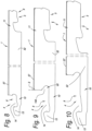
- Figures 8 to 10 represent, by way of example, three embodiments of the invention with mutually somewhat varied profile forms for the coupling parts.
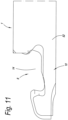
- Figure 11 represents the groove sides of figures 8 and 9 , however, rescaled to the same thickness and projected one above the other.
- the embodiments of figures 9 and 10 are particularly suitable for embodiments in MDF or HDF.
Landscapes
- Engineering & Computer Science (AREA)
- Architecture (AREA)
- Civil Engineering (AREA)
- Structural Engineering (AREA)
- Floor Finish (AREA)
- Finishing Walls (AREA)
Claims (15)
- Fußbodenpaneel zur Herstellung eines Bodenbelags;wobei das Fußbodenpaneel (1) ein erstes Paar von Gegenkantern (2-3) sowie ein zweites Paar von Gegenkanten (4-5) aufweist;wobei das erste Paar von Gegenkanten (2-3) Kupplungselemente (6-7) umfasst, die es ermöglichen zwei derartige Fußbodenpaneele (1) wechselseitig miteinander zu koppeln; und wobei diese Kupplungselemente (6-7) die nachstehend angegebenen Merkmale aufweisen:- die Kupplungselemente (6-7) umfassen ein in der horizontalen Richtung aktives Verriegelungssystem (HL), das in dem gekoppelten Zustand von zwei solchen Fußbodenpaneelen (1) eine Verriegelung in der Ebene der Fußbodenpaneele (1) und senkrecht zu den jeweiligen Kanten (2-3) bewirkt;- die Kupplungselemente (6-7) umfassen auch ein in der vertikalen Richtung aktives Verriegelungssystem (VL), das in dem gekoppelten Zustand von zwei solchen Fußbodenpaneelen (1) eine Verriegelung in einer Richtung quer zur Ebene der Fußbodenpaneele (1) bewirkt;- die Kupplungselemente (6-7) sind im Wesentlichen hergestellt aus dem Material der Fußbodenpaneele (1) selbst; und- die Kupplungselemente (6-7) sind so konfiguriert, dass zwei derartige Fußbodenpaneele (1) an diesen Kanten mittels einer Drehbewegung (R) miteinander gekoppelt werden können;wobei das zweite Paar gegenüberliegender Kanten (4-5) auch Kupplungselemente (8-9) an beiden Kanten umfasst, die es ermöglichen, zwei derartige Fußbodenpaneele (1) wechselseitig miteinander zu koppeln; und wobei diese Kupplungselemente (8-9) die nachfolgend angegebenen Merkmale aufweisen:- die Kupplungselemente (8-9) umfassen ein in horizontaler Richtung aktives Verriegelungssystem, das in dem gekoppelten Zustand von zwei solchen Fußbodenpaneelen (1) eine Verriegelung in der Ebene der Fußbodenpaneele (1) und senkrecht zu den jeweiligen Kanten (4-5) bewirkt;- die Kupplungselemente (8-9) umfassen auch ein in der vertikalen Richtung aktives Verriegelungssystem, das in dem gekoppelten Zustand von zwei solchen Fußbodenpaneelen (1) eine Verriegelung in einer Richtung quer zur Ebene der Fußbodenpaneele (1) bewirkt;- die Kupplungselemente (8-9) sind im Wesentlichen hergestellt aus dem Material der Fußbodenpaneel (1) selbst;- das in der horizontalen Richtung aktive Verriegelungssystem des zweiten Paares von Kanten (4-5) besteht zumindest aus einem unteren nach oben gerichteten Element (10), das eine hakenförmige Konfiguration aufweist, das sich an einer der beiden Kanten (4) befindet, sowie aus einem oberen nach unten gerichteten Element (11), das eine hakenförmige Konfiguration aufweist, das sich an der gegenüberliegenden Kante (5) befindet; wobei das untere Element (10), das eine hakenförmige Konfiguration aufweist, aus einer Lippe (12) besteht, die ein nach oben gerichtetes Verriegelungselement (13) aufweist, das an seiner proximalen Seite ein weibliches Element (14) in Form einer Aussparung definiert, während das obere Element (11), das eine hakenförmige Konfiguration aufweist, aus einer Lippe (15) besteht, die ein nach unten gerichtetes Verriegelungselement (16) aufweist, das ein männliches Element (17) bildet;- die Kupplungselemente (8-9) so konfiguriert sind, dass zwei derartige Fußbodenpaneele (1) jeweils an ihren jeweiligen Kanten (4-5) mittels einer nach unten gerichteten Bewegung (M) des einen Fußbodenpaneels relativ zu dem anderen miteinander gekoppelt werden können;- das in der vertikalen Richtung aktive Verriegelungssystem des zweiten Kantenpaares (4-5) umfasst in der vertikalen Richtung aktive Verriegelungselemente (18, 19, 20, 21), die mittels jeweiliger Kontaktflächen (22, 23, 24, 25) mindestens einen ersten Kontaktbereich (C1) und einen zweiten Kontaktbereich (C2) definieren, die sich auf gegenüberliegenden Seiten des männlichen Elements (17) und des weiblichen Elements (14) befinden;- die oben erwähnten, in der vertikalen Richtung aktiven Verriegelungselemente umfassen ein erstes Verriegelungselement (18) und ein zweites Verriegelungselement (19) an den jeweiligen gegenüberliegenden Kanten (26, 27) des männlichen Elements (17) sowie ein drittes Verriegelungselement (20) und ein viertes Verriegelungselement (21) an den jeweiligen gegenüberliegenden Kanten (28, 29) des weiblichen Elements (14);- in dem gekoppelten Zustand zweier solcher Fußbodenpaneele (1) definieren das erste und das dritte Verriegelungselement (18, 20) den ersten Kontaktbereich (C1); wobei sie Kontaktflächen (22, 24) haben, die in dem gekoppelten Zustand mindestens eine geneigte Tangentiallinie (T1) definieren;- in dem gekoppelten Zustand zweier solcher Fußbodenpaneele (1) definieren das zweite und das vierte Verriegelungselement (19, 21) den zweiten Kontaktbereich (C2); wobei sie Kontaktflächen (23, 25) haben, die in dem gekoppelten Zustand auch mindestens eine geneigte Tangentenlinie (T2) definieren;- das männliche Element (17), das oben erwähnt wurde, hat eine distale Seite (27) und eine proximale Seite (26); wobei das zweite Verriegelungselement (19) an der distalen Seite (27) angebracht ist;- die beiden oben erwähnten Tangentenlinien (T1-T2) sind von ihren jeweiligen Kontaktbereichen (C1-C2) aus in Richtung zueinander nach oben geneigt;- in Bezug auf die Ebene des Fußbodenpaneels (1) ist die Tangente (T1), die durch das erste und das zweite Verriegelungselement (18, 20) definiert wird, steiler als die Tangente (T2), die durch das zweite und das vierte Verriegelungselement (19, 21) definiert wird, oder anders ausgedrückt, der Winkel (A1), den die zuerst erwähnte Tangente (T1) mit der Horizontalen bildet, ist größer als der Winkel (A2), den die später erwähnte Tangente (T2) mit der Horizontalen bildet;- der Unterschied in der Abmessung zwischen den beiden genannten Winkeln (A1-A2) beträgt mindestens 5 Grad und vorzugsweise mindestens 10 Grad;- an dem männlichen Element (17) ist in einer Höhe, die niedriger ist als der zweite Kontaktbereich (C2), mindestens eine Kontaktfläche (30A und/oder 30B) vorgesehen, die in dem gekoppelten Zustand zusammen mit einer Kontaktfläche (31A und/oder 31B) an dem weiblichen Element (14) des dann gekoppelten Fußbodenpaneels einen Stützpunkt (32A und/oder 32B) bildet, der die Bewegung des männlichen Elements (17) in der nach unten gerichteten Richtung begrenzt;wobei eine Verschlussebene (S) an dem zweiten Paar gegenüberliegender Kanten (4, 5) als eine vertikale Ebene definiert ist, die sich durch die oberen Kanten (41-42) der gekoppelten Fußbodenpaneele, oder zumindest dort, wo sich die Fußbodenpaneele (1) oben treffen, erstreckt;dadurch gekennzeichnet, dass- unterhalb des vierten Verriegelungselements ein Einschnitt (14A) vorhanden ist, der sich in der proximalen Richtung in das Fußbodenpaneel (1) hinein erstreckt, wodurch die Lippe (12) des unteren Elements mit einer hakenförmigen Konfiguration durchtrennt wird; wobei dieser Einschnitt (14A) sich nach innen über eine Strecke erstreckt, die, gemessen von der vertikalen Schließebene (S), eine horizontale Tiefe aufweist, die mindestens 1/10 und noch besser mindestens 1/7 der horizontalen Strecke (HM) beträgt, die sich zwischen der Mitte des ersten Kontaktbereichs (C1) und der Mitte des zweiten Kontaktbereichs (C2) erstreckt.
- Fußbodenpaneel nach Anspruch 1, dadurch gekennzeichnet, dass die Kupplungselemente des zweiten Kantenpaares einstückig aus MDF (mitteldichte Faserpaneele) oder HDF (hochdichte Faserpaneele) gefertigt sind.
- Fußbodenpaneel nach Anspruch 2, dadurch gekennzeichnet, dass das Fußbodenpaneel ein Substrat (52) aus MDF oder HDF umfasst, das sich über seine gesamte oder annähernd gesamte Oberfläche erstreckt; wobei die Kupplungselemente, die oben erwähnt wurden, an den Kanten ausgebildet sind.
- Fußbodenpaneel nach Anspruch 2 oder 3, dadurch gekennzeichnet, dass das Fußbodenpaneel eine dekorative Deckschicht (57) umfasst.
- Fußbodenpaneel nach Anspruch 4, dadurch gekennzeichnet, dass die Deckschicht (57) aus DPL (Direktdrucklaminat), HPL (Hochdrucklaminat), Furnierholz, einer Schicht aus Vollholz, Kork, einer oder mehreren bedruckten Schichten, einer oder mehreren Lackschichten oder einer Schicht aus synthetischem Material, wie z. B. Vinyl, oder einer Kombination aus zwei oder mehreren der oben genannten Schichten besteht.
- Fußbodenpaneel nach Anspruch 1, dadurch gekennzeichnet, dass es ein Substrat (52) auf der Basis eines synthetischen Materials umfasst, das mehrere Schichten umfasst oder auch nicht; wobei die Kupplungselemente von mindestens dem zweiten Paar von Kanten (4-5) in einem Stück aus dem Material des Paneels, insbesondere aus dem Material des Substrats (52), hergestellt sind; und wobei das Fußbodenpaneel vorzugsweise mit einer dekorativen Deckschicht versehen ist.
- Fußbodenpaneel nach Anspruch 6, dadurch gekennzeichnet, dass es sich um ein sogenanntes LVT-Bodenpaneel ("Luxus-Vinylfliese") handelt, sei es vom Typ "elastisch" oder vom Typ "starr", oder dass es sich um ein vergleichbares Fußbodenpaneel auf der Basis eines anderen Kunststoffs als Vinyl handelt, z. B. Polyurethan ; oder dass es sich um eine Fußbodenpaneel auf Kunststoffbasis handelt, das ein Substrat umfasst, das aus mindestens zwei Schichten besteht, insbesondere aus einer Substratschicht, die aus einem geschäumten und gefüllten Kunststoff hergestellt ist und vorzugsweise eine Dicke aufweist, die mehr als die Hälfte der Gesamtdicke des Fußbodenpaneels beträgt, und einer Schicht aus nicht geschäumtem oder weniger geschäumtem Kunststoff, die eine Dicke von mindestens 1 mm aufweist, die über der Substratschicht vorgesehen ist, z. B. eine Schicht auf Vinylbasis, auf der dann vorzugsweise eine dekorative Deckschicht vorhanden ist.
- Fußbodenpaneel nach einem der vorhergehenden Ansprüche, dadurch gekennzeichnet, dass das untere Element (10), das an der distalen Seite (33) seines distalen Endes (34) eine hakenförmige Konfiguration besitzt, frei von mechanischen Verriegelungselementen ist, die in der vertikalen Richtung wirksam sind.
- Fußbodenpaneel nach Anspruch 8, dadurch gekennzeichnet, dass in dem gekoppelten Zustand hinter dem distalen Ende (34) des unteren Elements, das eine hakenförmige Konfiguration besitzt, ein Zwischenraum (55) vorhanden ist.
- Fußbodenpaneel nach einem der vorhergehenden Ansprüche, dadurch gekennzeichnet, dass die beiden Kontaktflächen des zweiten Kontaktbereichs (C2), einschließlich etwaiger Verlängerungen dieser Flächen, bei Betrachtung in einer Querschnittsansicht sich sowohl nach links als auch nach rechts von der jeweiligen Schließebene (S) erstrecken ; wobei die Verschlussebene als eine vertikale Ebene definiert ist, die sich durch die oberen Kanten (41-42) der gekoppelten Fußbodenpaneele oder zumindest dort, wo sich die Fußbodenpaneele (1) oben treffen, erstreckt.
- Fußbodenpaneel nach einem der vorhergehenden Ansprüche, dadurch gekennzeichnet, dass an der Unterseite der Lippe (12) des Bodenelements (10), das eine hakenförmige Konfiguration aufweist, eine Aussparung (45) vorhanden ist, die sich bis zum distalen Ende der Lippe erstreckt, wobei die Aussparung eine Abwärtsbiegung der Lippe oder jedenfalls mindestens eines Teils davon ermöglicht; wobei die Aussparung vorzugsweise so konfiguriert ist, dass die oben erwähnte Abwärtsbiegung im Wesentlichen eine nach oben gerichtete Kippbewegung des Verriegelungselements (13) bewirkt; wobei auf diese Weise in dem Abschnitt der Lippe, der sich direkt proximal zu dem nach oben gerichteten Verriegelungselement befindet, keine Abwärtsbiegung oder eine leichte Biegung stattfindet, oder zumindest in einem geringeren Ausmaß stattfindet als in dem Abschnitt, der das Verriegelungselement trägt.
- Fußbodenpaneel nach einem der vorhergehenden Ansprüche, dadurch gekennzeichnet, dass an den unteren Kanten des männlichen Elements Führungsflächen (48-49), wie Fasen oder Rundungen, vorhanden sind, die so ausgebildet sind, dass das männliche Element (17) bei seiner nach unten gerichteten Bewegung selbsttätig in das weibliche Element (14) geführt wird, an dem die erforderlichen Führungsflächen ebenfalls vorhanden sein können; und dass das männliche Element mit zumindest dem unteren Abschnitt in das weibliche Element eingeführt wird, bevor eine Trenn- und Druckkraft dadurch entsteht, dass sich die Verriegelungselemente des zweiten Kontaktbereichs zunächst aneinander entlang bewegen.
- Fußbodenpaneel nach einem der vorhergehenden Ansprüche, dadurch gekennzeichnet, dass die Tangentenlinie (T2) in der zweiten Kontaktzone (C2) einen Winkel mit der Horizontalen bildet, der kleiner als 50 Grad, noch besser kleiner als 45 Grad und noch besser kleiner als 30 Grad ist.
- Fußbodenpaneel nach einem der vorhergehenden Ansprüche, dadurch gekennzeichnet, dass die Kupplungselemente an dem zweiten Kantenpaar (4-5) so ausgebildet sind, dass sie in dem gekoppelten Zustand eine sogenannte Vorspannung erzeugen.
- Fußbodenpaneel nach einem der vorhergehenden Ansprüche, dadurch gekennzeichnet, dass das nach oben gerichtete Verriegelungselement (13), das nach unten gerichtete Verriegelungselement (16) und die betreffenden Kontaktflächen des ersten Kontaktbereichs (C1) derart ausgebildet sind, dass das nach oben gerichtete Verriegelungselement (13) mit seiner betreffenden Kontaktfläche in dem gekoppelten Zustand eine Position einnimmt, die gegenüber der Position, die diese Kontaktfläche in dem ungekoppelten Zustand einnimmt, etwas geneigt ist; und dass die beiden Kontaktflächen des ersten Kontaktbereichs in dem ungekoppelten Zustand mit einem solchen gegenseitigen Abstand orientiert sind, dass sich in dem gekoppelten Zustand eine Orientierung mit einem gegenseitigen Abstand ergibt, der kleiner oder gleich null ist.
Priority Applications (3)
| Application Number | Priority Date | Filing Date | Title |
|---|---|---|---|
| EP24200954.6A EP4459067A2 (de) | 2017-03-21 | 2018-03-21 | Bodenplatte zur bildung eines bodenbelags |
| PL20172384T PL3725974T3 (pl) | 2017-03-21 | 2018-03-21 | Panel do formowania pokrycia |
| EP20172384.8A EP3725974B1 (de) | 2017-03-21 | 2018-03-21 | Paneel zur formung eines belags |
Applications Claiming Priority (2)
| Application Number | Priority Date | Filing Date | Title |
|---|---|---|---|
| US201762474494P | 2017-03-21 | 2017-03-21 | |
| PCT/IB2018/051898 WO2018172955A2 (en) | 2017-03-21 | 2018-03-21 | Floor panel for forming a floor covering |
Related Child Applications (4)
| Application Number | Title | Priority Date | Filing Date |
|---|---|---|---|
| EP24200954.6A Division-Into EP4459067A2 (de) | 2017-03-21 | 2018-03-21 | Bodenplatte zur bildung eines bodenbelags |
| EP24200954.6A Division EP4459067A2 (de) | 2017-03-21 | 2018-03-21 | Bodenplatte zur bildung eines bodenbelags |
| EP20172384.8A Division-Into EP3725974B1 (de) | 2017-03-21 | 2018-03-21 | Paneel zur formung eines belags |
| EP20172384.8A Division EP3725974B1 (de) | 2017-03-21 | 2018-03-21 | Paneel zur formung eines belags |
Publications (2)
| Publication Number | Publication Date |
|---|---|
| EP3601702A2 EP3601702A2 (de) | 2020-02-05 |
| EP3601702B1 true EP3601702B1 (de) | 2024-11-13 |
Family
ID=62046981
Family Applications (3)
| Application Number | Title | Priority Date | Filing Date |
|---|---|---|---|
| EP24200954.6A Pending EP4459067A2 (de) | 2017-03-21 | 2018-03-21 | Bodenplatte zur bildung eines bodenbelags |
| EP20172384.8A Active EP3725974B1 (de) | 2017-03-21 | 2018-03-21 | Paneel zur formung eines belags |
| EP18720002.7A Active EP3601702B1 (de) | 2017-03-21 | 2018-03-21 | Bodenplatte zur formung eines bodenbelags |
Family Applications Before (2)
| Application Number | Title | Priority Date | Filing Date |
|---|---|---|---|
| EP24200954.6A Pending EP4459067A2 (de) | 2017-03-21 | 2018-03-21 | Bodenplatte zur bildung eines bodenbelags |
| EP20172384.8A Active EP3725974B1 (de) | 2017-03-21 | 2018-03-21 | Paneel zur formung eines belags |
Country Status (10)
| Country | Link |
|---|---|
| US (5) | US11136765B2 (de) |
| EP (3) | EP4459067A2 (de) |
| KR (1) | KR102535444B1 (de) |
| CN (3) | CN110431276B (de) |
| CA (1) | CA3056031A1 (de) |
| ES (1) | ES2910350T3 (de) |
| PL (1) | PL3725974T3 (de) |
| PT (1) | PT3725974T (de) |
| RU (1) | RU2754157C2 (de) |
| WO (1) | WO2018172955A2 (de) |
Families Citing this family (13)
| Publication number | Priority date | Publication date | Assignee | Title |
|---|---|---|---|---|
| BE1024723B1 (nl) * | 2016-11-10 | 2018-06-11 | Ivc Bvba | Vloerpaneel en werkwijze voor het vervaardigen van een vloerpaneel. |
| EP3581732B1 (de) * | 2018-06-15 | 2022-12-07 | Akzenta Paneele + Profile GmbH | Paneel mit dichtungsrille und dichtungsleiste |
| NL2021885B1 (en) | 2018-10-26 | 2020-05-13 | I4F Licensing Nv | Multi-purpose tile system, tile covering, and tile |
| US11952784B2 (en) * | 2019-01-30 | 2024-04-09 | I4F Licensing Nv | Panel and covering comprising the same |
| EP3798386A1 (de) * | 2019-09-24 | 2021-03-31 | Välinge Innovation AB | Panelsatz mit mechanisch verriegelbaren kanten |
| EP4069917B1 (de) | 2019-12-03 | 2025-07-09 | Unilin, BV | Bodenpaneel zur formung eines bodenbelags |
| SE544438C2 (en) | 2019-12-13 | 2022-05-31 | Vilox Ab | Releasable joining system for floor panels, a floor panel, a floor system, a method for laying and a method for releasing a floor panel |
| LU101663B1 (en) * | 2020-03-06 | 2021-09-14 | Tarkett Gdl Sa | Set of surface covering planks and method of connecting thereof |
| BE1028427B1 (nl) * | 2020-06-24 | 2022-02-01 | Flooring Ind Ltd Sarl | Vloerpanelen en werkwijze voor het vervaardigen van vloerpanelen en snijgereedschappen hierbij aangewend |
| CA3123999A1 (en) * | 2021-07-06 | 2023-01-06 | Clayton P. Fearon | Improved interlocking building panel |
| ES2973821T3 (es) * | 2021-08-23 | 2024-06-24 | Fritz Egger Gmbh & Co Og | Panel, en particular, panel de suelo, con función de estanqueización |
| BE1029978B1 (nl) | 2021-12-02 | 2023-07-03 | Flooring Ind Ltd Sarl | Decoratief paneel. |
| NL2036705B1 (en) * | 2023-12-28 | 2025-07-11 | I4F Licensing Nv | Floor board and method for manufacturing such floor board |
Family Cites Families (55)
| Publication number | Priority date | Publication date | Assignee | Title |
|---|---|---|---|---|
| US3590613A (en) * | 1969-11-25 | 1971-07-06 | Gen Motors Corp | Coincidental vehicle steering column and floor shift lock |
| US3720150A (en) | 1971-02-16 | 1973-03-13 | Memorex Corp | Diazo film developer |
| US4736552A (en) * | 1984-10-03 | 1988-04-12 | Ward Lonnie R | Roof insulation system and method of fabrication therefor |
| US7131242B2 (en) * | 1995-03-07 | 2006-11-07 | Pergo (Europe) Ab | Flooring panel or wall panel and use thereof |
| SE9500810D0 (sv) * | 1995-03-07 | 1995-03-07 | Perstorp Flooring Ab | Golvplatta |
| US6421970B1 (en) * | 1995-03-07 | 2002-07-23 | Perstorp Flooring Ab | Flooring panel or wall panel and use thereof |
| SE512313E (sv) * | 1998-06-03 | 2004-03-16 | Valinge Aluminium Ab | Låssystem samt golvskiva |
| JP4312284B2 (ja) | 1998-08-21 | 2009-08-12 | 東北リコー株式会社 | 孔版印刷装置 |
| IL129834A (en) * | 1999-05-06 | 2001-09-13 | Ackerstein Ind Ltd | Ground surface cover system with flexible interlocking joint for erosion control |
| EP1243721A3 (de) * | 1999-06-30 | 2003-07-09 | Akzenta Paneele + Profile GmbH | Fussbodenbelag, Paneel sowie Befestigungssystem für Paneele |
| DE20008708U1 (de) * | 2000-05-16 | 2000-09-14 | Kronospan Technical Co. Ltd., Nikosia | Paneele mit Kupplungsmitteln |
| DE10026613A1 (de) * | 2000-05-30 | 2001-12-06 | Heuel & Soehne Gmbh J | Befestigungseinheit für die Befestigung von Dachkomponenten an einem gebördelten Verbindungsbereich zweier nebeneinander angeordneter Dachabschnitte eines Aluminiumdachs |
| DE20122553U1 (de) * | 2001-08-10 | 2006-03-23 | Akzenta Paneele + Profile Gmbh | Paneel sowie Befestigungssystem für Paneele |
| RU2302498C2 (ru) * | 2002-04-03 | 2007-07-10 | Велинге Инновейшн Аб | Механическая запирающая система для досок настила |
| US8850769B2 (en) * | 2002-04-15 | 2014-10-07 | Valinge Innovation Ab | Floorboards for floating floors |
| US7926236B2 (en) * | 2003-06-27 | 2011-04-19 | Konvin Associates Limited Partnership | Light transmission panels, retaining clip and a combination thereof |
| US7313893B2 (en) * | 2003-11-13 | 2008-01-01 | Extech/Exterior Technologies, Inc. | Panel clip assembly for use with roof or wall panels |
| DE102004012582A1 (de) * | 2004-03-12 | 2005-10-06 | Hülsta-Werke Hüls Gmbh & Co. Kg | Paneelelement |
| ATE535660T1 (de) * | 2004-10-22 | 2011-12-15 | Vaelinge Innovation Ab | Verfahren zur anbringung eines mechanischen verriegelungssystems auf fussbodenpaneele |
| US7841144B2 (en) * | 2005-03-30 | 2010-11-30 | Valinge Innovation Ab | Mechanical locking system for panels and method of installing same |
| SE529076C2 (sv) * | 2005-07-11 | 2007-04-24 | Pergo Europ Ab | En fog till paneler |
| US7661234B2 (en) * | 2005-08-10 | 2010-02-16 | Extech/Exterior Technologies, Inc. | Reduced friction fastening clip assembly for use with standing seam roof or wall panel systems |
| DE102006011887A1 (de) * | 2006-01-13 | 2007-07-19 | Akzenta Paneele + Profile Gmbh | Sperrelement, Paneel mit separatem Sperrelement, Verfahren zur Installation eines Paneelbelags aus Paneelen mit Sperrelementen sowie Verfahren und Vorrichtung zur Vormontage eines Sperrelements an einem Paneel |
| SE529506C2 (sv) * | 2006-02-03 | 2007-08-28 | Pergo Europ Ab | Ett fogskydd för paneler |
| BE1017157A3 (nl) * | 2006-06-02 | 2008-03-04 | Flooring Ind Ltd | Vloerbekleding, vloerelement en werkwijze voor het vervaardigen van vloerelementen. |
| DE102006057491A1 (de) * | 2006-12-06 | 2008-06-12 | Akzenta Paneele + Profile Gmbh | Paneel sowie Bodenbelag |
| SE531111C2 (sv) * | 2006-12-08 | 2008-12-23 | Vaelinge Innovation Ab | Mekanisk låsning av golvpaneler |
| US7726088B2 (en) * | 2007-07-20 | 2010-06-01 | Moritz Andre Muehlebach | Flooring system |
| DE102007042250B4 (de) * | 2007-09-06 | 2010-04-22 | Flooring Technologies Ltd. | Einrichtung zur Verbindung und Verriegelung zweier Bauplatten, insbesondere Fussbodenpaneele |
| US8029880B2 (en) * | 2008-04-24 | 2011-10-04 | Liu David C | Water resistant wide flooring boards |
| BE1018627A5 (nl) * | 2009-01-16 | 2011-05-03 | Flooring Ind Ltd Sarl | Vloerpaneel. |
| BE1018728A3 (nl) * | 2009-04-22 | 2011-07-05 | Flooring Ind Ltd Sarl | Vloerpaneel. |
| DE102009022483A1 (de) * | 2009-05-25 | 2010-12-02 | Pergo (Europe) Ab | Set von Paneelen, insbesondere von Fußbodenpaneelen |
| NL2003019C2 (nl) * | 2009-06-12 | 2010-12-15 | 4Sight Innovation Bv | Vloerpaneel en vloerbedekking bestaande uit meerdere van dergelijke vloerpanelen. |
| US8429870B2 (en) * | 2009-12-04 | 2013-04-30 | Mannington Mills, Inc. | Connecting system for surface coverings |
| LT2339092T (lt) | 2009-12-22 | 2019-07-25 | Flooring Industries Limited, Sarl | Dangos plokščių gamybos būdas |
| WO2011087425A1 (en) * | 2010-01-12 | 2011-07-21 | Välinge Innovation AB | Mechanical locking system for floor panels |
| WO2011141043A1 (en) * | 2010-05-10 | 2011-11-17 | Pergo AG | Set of panels |
| PL2423410T3 (pl) | 2010-08-27 | 2013-07-31 | Barlinek Sa | Panel budowlany z ulepszonymi środkami ryglującymi do rozłącznego łączenia z panelami budowlanymi tego samego rodzaju |
| RU2551593C2 (ru) * | 2010-10-20 | 2015-05-27 | Кроноплюс Техникаль АГ | Покрытие с ламинатными панелями и внешний закрепляющий элемент |
| DE102010063976B4 (de) * | 2010-12-22 | 2013-01-17 | Akzenta Paneele + Profile Gmbh | Paneel |
| DE102011086846A1 (de) * | 2011-01-28 | 2012-08-02 | Akzenta Paneele + Profile Gmbh | Paneel |
| BE1020433A3 (nl) | 2012-01-05 | 2013-10-01 | Flooring Ind Ltd Sarl | Paneel. |
| BE1022209B1 (nl) * | 2012-01-12 | 2016-03-01 | I.V.C. N.V. | Vloerpaneel |
| WO2013118030A2 (en) | 2012-02-07 | 2013-08-15 | Flooring Industries Limited, Sarl | Floor panel for forming a floor covering, floor covering formed from such floor panels and method for manufacturing such floor panels. |
| EP2895667B1 (de) * | 2012-08-27 | 2019-12-04 | Pergo (Europe) AB | Tafel |
| CN104968873B (zh) * | 2013-01-11 | 2018-03-27 | 地板工业有限公司 | 用于形成地板覆层的地板镶板,由这种地板镶板形成的地板覆层以及制造这种地板镶板的方法 |
| PL3105392T3 (pl) * | 2014-02-26 | 2017-09-29 | Innovations 4 Flooring Holding N.V. | Panel łączony wzajemnie z podobnymi panelami w celu utworzenia pokrycia |
| US9260870B2 (en) * | 2014-03-24 | 2016-02-16 | Ivc N.V. | Set of mutually lockable panels |
| EP3839170B1 (de) * | 2014-09-26 | 2024-07-17 | Unilin, BV | Bodenplatte zur formung eines bodenbelags und verfahren zur herstellung einer bodenplatte |
| WO2016057706A1 (en) | 2014-10-07 | 2016-04-14 | AlignCare Services, LLC. | System and method for improving health care management and compliance |
| CN110644720B (zh) * | 2014-12-22 | 2022-03-04 | 塞拉洛克创新股份有限公司 | 用于地板镶板的机械锁定系统 |
| US9567755B2 (en) * | 2014-12-23 | 2017-02-14 | Afi Licensing Llc | Sound-absorbing interlocking floor panels and system |
| BE1023779B1 (nl) * | 2015-12-31 | 2017-07-24 | Flooring Industries Limited Sarl | Vloerpaneel voor het vormen van een vloerbekleding |
| US10648182B2 (en) | 2015-12-31 | 2020-05-12 | Flooring Industries Limited, Sarl | Floor panel for forming a floor covering |
-
2018
- 2018-03-21 CN CN201880018868.0A patent/CN110431276B/zh active Active
- 2018-03-21 EP EP24200954.6A patent/EP4459067A2/de active Pending
- 2018-03-21 CN CN202110721631.2A patent/CN113356509A/zh active Pending
- 2018-03-21 EP EP20172384.8A patent/EP3725974B1/de active Active
- 2018-03-21 WO PCT/IB2018/051898 patent/WO2018172955A2/en not_active Ceased
- 2018-03-21 EP EP18720002.7A patent/EP3601702B1/de active Active
- 2018-03-21 PT PT201723848T patent/PT3725974T/pt unknown
- 2018-03-21 CA CA3056031A patent/CA3056031A1/en not_active Abandoned
- 2018-03-21 ES ES20172384T patent/ES2910350T3/es active Active
- 2018-03-21 US US16/496,230 patent/US11136765B2/en active Active
- 2018-03-21 CN CN202110721459.0A patent/CN113356508A/zh active Pending
- 2018-03-21 RU RU2019133128A patent/RU2754157C2/ru active
- 2018-03-21 KR KR1020197029595A patent/KR102535444B1/ko active Active
- 2018-03-21 PL PL20172384T patent/PL3725974T3/pl unknown
-
2021
- 2021-08-02 US US17/391,420 patent/US11591807B2/en active Active
-
2023
- 2023-01-20 US US18/099,428 patent/US12024899B2/en active Active
-
2024
- 2024-01-29 US US18/425,720 patent/US12312817B2/en active Active
-
2025
- 2025-04-25 US US19/189,689 patent/US20250263936A1/en active Pending
Also Published As
| Publication number | Publication date |
|---|---|
| US12024899B2 (en) | 2024-07-02 |
| CA3056031A1 (en) | 2018-09-27 |
| PT3725974T (pt) | 2022-03-01 |
| CN110431276A (zh) | 2019-11-08 |
| EP3601702A2 (de) | 2020-02-05 |
| WO2018172955A2 (en) | 2018-09-27 |
| CN113356508A (zh) | 2021-09-07 |
| US11591807B2 (en) | 2023-02-28 |
| CN113356509A (zh) | 2021-09-07 |
| RU2019133128A3 (de) | 2021-06-24 |
| US20210355689A1 (en) | 2021-11-18 |
| RU2021124548A (ru) | 2021-09-13 |
| US20250263936A1 (en) | 2025-08-21 |
| KR102535444B1 (ko) | 2023-05-22 |
| RU2019133128A (ru) | 2021-04-21 |
| CN110431276B (zh) | 2021-08-10 |
| US20200277796A1 (en) | 2020-09-03 |
| US11136765B2 (en) | 2021-10-05 |
| ES2910350T3 (es) | 2022-05-12 |
| RU2754157C2 (ru) | 2021-08-30 |
| EP3725974A1 (de) | 2020-10-21 |
| US20240218671A1 (en) | 2024-07-04 |
| WO2018172955A3 (en) | 2018-11-22 |
| KR20190126378A (ko) | 2019-11-11 |
| EP3725974B1 (de) | 2022-02-09 |
| US12312817B2 (en) | 2025-05-27 |
| US20230160218A1 (en) | 2023-05-25 |
| PL3725974T3 (pl) | 2022-05-30 |
| EP4459067A2 (de) | 2024-11-06 |
Similar Documents
| Publication | Publication Date | Title |
|---|---|---|
| US12312817B2 (en) | Floor panel for forming a floor covering | |
| US11015351B2 (en) | Floor panel for forming a floor covering | |
| AU2022200043B2 (en) | Floor panel for forming a floor covering | |
| EP3973115B1 (de) | Bodenplatte zur formung eines bodenbelags | |
| EP4172429B1 (de) | Fussbodenplatten und verfahren zur herstellung von fussbodenplatten und schneidwerkzeuge dafür | |
| RU2839993C2 (ru) | Панель пола для образования напольного покрытия (варианты) |
Legal Events
| Date | Code | Title | Description |
|---|---|---|---|
| STAA | Information on the status of an ep patent application or granted ep patent |
Free format text: STATUS: UNKNOWN |
|
| STAA | Information on the status of an ep patent application or granted ep patent |
Free format text: STATUS: THE INTERNATIONAL PUBLICATION HAS BEEN MADE |
|
| PUAI | Public reference made under article 153(3) epc to a published international application that has entered the european phase |
Free format text: ORIGINAL CODE: 0009012 |
|
| STAA | Information on the status of an ep patent application or granted ep patent |
Free format text: STATUS: REQUEST FOR EXAMINATION WAS MADE |
|
| 17P | Request for examination filed |
Effective date: 20191008 |
|
| AK | Designated contracting states |
Kind code of ref document: A2 Designated state(s): AL AT BE BG CH CY CZ DE DK EE ES FI FR GB GR HR HU IE IS IT LI LT LU LV MC MK MT NL NO PL PT RO RS SE SI SK SM TR |
|
| AX | Request for extension of the european patent |
Extension state: BA ME |
|
| DAV | Request for validation of the european patent (deleted) | ||
| DAX | Request for extension of the european patent (deleted) | ||
| STAA | Information on the status of an ep patent application or granted ep patent |
Free format text: STATUS: EXAMINATION IS IN PROGRESS |
|
| 17Q | First examination report despatched |
Effective date: 20201012 |
|
| RAP1 | Party data changed (applicant data changed or rights of an application transferred) |
Owner name: UNILIN, BV |
|
| GRAP | Despatch of communication of intention to grant a patent |
Free format text: ORIGINAL CODE: EPIDOSNIGR1 |
|
| STAA | Information on the status of an ep patent application or granted ep patent |
Free format text: STATUS: GRANT OF PATENT IS INTENDED |
|
| INTG | Intention to grant announced |
Effective date: 20240510 |
|
| GRAJ | Information related to disapproval of communication of intention to grant by the applicant or resumption of examination proceedings by the epo deleted |
Free format text: ORIGINAL CODE: EPIDOSDIGR1 |
|
| STAA | Information on the status of an ep patent application or granted ep patent |
Free format text: STATUS: EXAMINATION IS IN PROGRESS |
|
| GRAP | Despatch of communication of intention to grant a patent |
Free format text: ORIGINAL CODE: EPIDOSNIGR1 |
|
| STAA | Information on the status of an ep patent application or granted ep patent |
Free format text: STATUS: GRANT OF PATENT IS INTENDED |
|
| INTC | Intention to grant announced (deleted) | ||
| INTG | Intention to grant announced |
Effective date: 20240719 |
|
| GRAS | Grant fee paid |
Free format text: ORIGINAL CODE: EPIDOSNIGR3 |
|
| GRAA | (expected) grant |
Free format text: ORIGINAL CODE: 0009210 |
|
| STAA | Information on the status of an ep patent application or granted ep patent |
Free format text: STATUS: THE PATENT HAS BEEN GRANTED |
|
| AK | Designated contracting states |
Kind code of ref document: B1 Designated state(s): AL AT BE BG CH CY CZ DE DK EE ES FI FR GB GR HR HU IE IS IT LI LT LU LV MC MK MT NL NO PL PT RO RS SE SI SK SM TR |
|
| P01 | Opt-out of the competence of the unified patent court (upc) registered |
Free format text: CASE NUMBER: APP_54501/2024 Effective date: 20241003 |
|
| REG | Reference to a national code |
Ref country code: GB Ref legal event code: FG4D |
|
| REG | Reference to a national code |
Ref country code: CH Ref legal event code: EP |
|
| REG | Reference to a national code |
Ref country code: IE Ref legal event code: FG4D |
|
| REG | Reference to a national code |
Ref country code: DE Ref legal event code: R096 Ref document number: 602018076510 Country of ref document: DE |
|
| REG | Reference to a national code |
Ref country code: NL Ref legal event code: FP |
|
| REG | Reference to a national code |
Ref country code: LT Ref legal event code: MG9D |
|
| PG25 | Lapsed in a contracting state [announced via postgrant information from national office to epo] |
Ref country code: PT Free format text: LAPSE BECAUSE OF FAILURE TO SUBMIT A TRANSLATION OF THE DESCRIPTION OR TO PAY THE FEE WITHIN THE PRESCRIBED TIME-LIMIT Effective date: 20250313 Ref country code: IS Free format text: LAPSE BECAUSE OF FAILURE TO SUBMIT A TRANSLATION OF THE DESCRIPTION OR TO PAY THE FEE WITHIN THE PRESCRIBED TIME-LIMIT Effective date: 20250313 Ref country code: HR Free format text: LAPSE BECAUSE OF FAILURE TO SUBMIT A TRANSLATION OF THE DESCRIPTION OR TO PAY THE FEE WITHIN THE PRESCRIBED TIME-LIMIT Effective date: 20241113 |
|
| PGFP | Annual fee paid to national office [announced via postgrant information from national office to epo] |
Ref country code: DE Payment date: 20250327 Year of fee payment: 8 |
|
| PG25 | Lapsed in a contracting state [announced via postgrant information from national office to epo] |
Ref country code: FI Free format text: LAPSE BECAUSE OF FAILURE TO SUBMIT A TRANSLATION OF THE DESCRIPTION OR TO PAY THE FEE WITHIN THE PRESCRIBED TIME-LIMIT Effective date: 20241113 |
|
| PGFP | Annual fee paid to national office [announced via postgrant information from national office to epo] |
Ref country code: NL Payment date: 20250327 Year of fee payment: 8 |
|
| REG | Reference to a national code |
Ref country code: AT Ref legal event code: MK05 Ref document number: 1741800 Country of ref document: AT Kind code of ref document: T Effective date: 20241113 |
|
| PG25 | Lapsed in a contracting state [announced via postgrant information from national office to epo] |
Ref country code: BG Free format text: LAPSE BECAUSE OF FAILURE TO SUBMIT A TRANSLATION OF THE DESCRIPTION OR TO PAY THE FEE WITHIN THE PRESCRIBED TIME-LIMIT Effective date: 20241113 |
|
| PG25 | Lapsed in a contracting state [announced via postgrant information from national office to epo] |
Ref country code: ES Free format text: LAPSE BECAUSE OF FAILURE TO SUBMIT A TRANSLATION OF THE DESCRIPTION OR TO PAY THE FEE WITHIN THE PRESCRIBED TIME-LIMIT Effective date: 20241113 |
|
| PG25 | Lapsed in a contracting state [announced via postgrant information from national office to epo] |
Ref country code: NO Free format text: LAPSE BECAUSE OF FAILURE TO SUBMIT A TRANSLATION OF THE DESCRIPTION OR TO PAY THE FEE WITHIN THE PRESCRIBED TIME-LIMIT Effective date: 20250213 |
|
| PG25 | Lapsed in a contracting state [announced via postgrant information from national office to epo] |
Ref country code: LV Free format text: LAPSE BECAUSE OF FAILURE TO SUBMIT A TRANSLATION OF THE DESCRIPTION OR TO PAY THE FEE WITHIN THE PRESCRIBED TIME-LIMIT Effective date: 20241113 Ref country code: AT Free format text: LAPSE BECAUSE OF FAILURE TO SUBMIT A TRANSLATION OF THE DESCRIPTION OR TO PAY THE FEE WITHIN THE PRESCRIBED TIME-LIMIT Effective date: 20241113 Ref country code: GR Free format text: LAPSE BECAUSE OF FAILURE TO SUBMIT A TRANSLATION OF THE DESCRIPTION OR TO PAY THE FEE WITHIN THE PRESCRIBED TIME-LIMIT Effective date: 20250214 |
|
| PGFP | Annual fee paid to national office [announced via postgrant information from national office to epo] |
Ref country code: BE Payment date: 20250327 Year of fee payment: 8 |
|
| PG25 | Lapsed in a contracting state [announced via postgrant information from national office to epo] |
Ref country code: PL Free format text: LAPSE BECAUSE OF FAILURE TO SUBMIT A TRANSLATION OF THE DESCRIPTION OR TO PAY THE FEE WITHIN THE PRESCRIBED TIME-LIMIT Effective date: 20241113 |
|
| PGFP | Annual fee paid to national office [announced via postgrant information from national office to epo] |
Ref country code: FR Payment date: 20250325 Year of fee payment: 8 |
|
| PG25 | Lapsed in a contracting state [announced via postgrant information from national office to epo] |
Ref country code: RS Free format text: LAPSE BECAUSE OF FAILURE TO SUBMIT A TRANSLATION OF THE DESCRIPTION OR TO PAY THE FEE WITHIN THE PRESCRIBED TIME-LIMIT Effective date: 20250213 |
|
| PGFP | Annual fee paid to national office [announced via postgrant information from national office to epo] |
Ref country code: TR Payment date: 20250311 Year of fee payment: 8 |
|
| PG25 | Lapsed in a contracting state [announced via postgrant information from national office to epo] |
Ref country code: SM Free format text: LAPSE BECAUSE OF FAILURE TO SUBMIT A TRANSLATION OF THE DESCRIPTION OR TO PAY THE FEE WITHIN THE PRESCRIBED TIME-LIMIT Effective date: 20241113 |
|
| PG25 | Lapsed in a contracting state [announced via postgrant information from national office to epo] |
Ref country code: DK Free format text: LAPSE BECAUSE OF FAILURE TO SUBMIT A TRANSLATION OF THE DESCRIPTION OR TO PAY THE FEE WITHIN THE PRESCRIBED TIME-LIMIT Effective date: 20241113 |
|
| PG25 | Lapsed in a contracting state [announced via postgrant information from national office to epo] |
Ref country code: EE Free format text: LAPSE BECAUSE OF FAILURE TO SUBMIT A TRANSLATION OF THE DESCRIPTION OR TO PAY THE FEE WITHIN THE PRESCRIBED TIME-LIMIT Effective date: 20241113 |
|
| PG25 | Lapsed in a contracting state [announced via postgrant information from national office to epo] |
Ref country code: RO Free format text: LAPSE BECAUSE OF FAILURE TO SUBMIT A TRANSLATION OF THE DESCRIPTION OR TO PAY THE FEE WITHIN THE PRESCRIBED TIME-LIMIT Effective date: 20241113 |
|
| PG25 | Lapsed in a contracting state [announced via postgrant information from national office to epo] |
Ref country code: SK Free format text: LAPSE BECAUSE OF FAILURE TO SUBMIT A TRANSLATION OF THE DESCRIPTION OR TO PAY THE FEE WITHIN THE PRESCRIBED TIME-LIMIT Effective date: 20241113 |
|
| PG25 | Lapsed in a contracting state [announced via postgrant information from national office to epo] |
Ref country code: CZ Free format text: LAPSE BECAUSE OF FAILURE TO SUBMIT A TRANSLATION OF THE DESCRIPTION OR TO PAY THE FEE WITHIN THE PRESCRIBED TIME-LIMIT Effective date: 20241113 |
|
| PG25 | Lapsed in a contracting state [announced via postgrant information from national office to epo] |
Ref country code: IT Free format text: LAPSE BECAUSE OF FAILURE TO SUBMIT A TRANSLATION OF THE DESCRIPTION OR TO PAY THE FEE WITHIN THE PRESCRIBED TIME-LIMIT Effective date: 20241113 |
|
| REG | Reference to a national code |
Ref country code: DE Ref legal event code: R097 Ref document number: 602018076510 Country of ref document: DE |
|
| PG25 | Lapsed in a contracting state [announced via postgrant information from national office to epo] |
Ref country code: SE Free format text: LAPSE BECAUSE OF FAILURE TO SUBMIT A TRANSLATION OF THE DESCRIPTION OR TO PAY THE FEE WITHIN THE PRESCRIBED TIME-LIMIT Effective date: 20241113 |
|
| PLBE | No opposition filed within time limit |
Free format text: ORIGINAL CODE: 0009261 |
|
| STAA | Information on the status of an ep patent application or granted ep patent |
Free format text: STATUS: NO OPPOSITION FILED WITHIN TIME LIMIT |
|
| PG25 | Lapsed in a contracting state [announced via postgrant information from national office to epo] |
Ref country code: MC Free format text: LAPSE BECAUSE OF FAILURE TO SUBMIT A TRANSLATION OF THE DESCRIPTION OR TO PAY THE FEE WITHIN THE PRESCRIBED TIME-LIMIT Effective date: 20241113 |
|
| 26N | No opposition filed |
Effective date: 20250814 |
|
| REG | Reference to a national code |
Ref country code: CH Ref legal event code: H13 Free format text: ST27 STATUS EVENT CODE: U-0-0-H10-H13 (AS PROVIDED BY THE NATIONAL OFFICE) Effective date: 20251023 |
|
| PG25 | Lapsed in a contracting state [announced via postgrant information from national office to epo] |
Ref country code: LU Free format text: LAPSE BECAUSE OF NON-PAYMENT OF DUE FEES Effective date: 20250321 |
|
| GBPC | Gb: european patent ceased through non-payment of renewal fee |
Effective date: 20250321 |
|
| PG25 | Lapsed in a contracting state [announced via postgrant information from national office to epo] |
Ref country code: GB Free format text: LAPSE BECAUSE OF NON-PAYMENT OF DUE FEES Effective date: 20250321 |
|
| PG25 | Lapsed in a contracting state [announced via postgrant information from national office to epo] |
Ref country code: CH Free format text: LAPSE BECAUSE OF NON-PAYMENT OF DUE FEES Effective date: 20250331 |
|
| PG25 | Lapsed in a contracting state [announced via postgrant information from national office to epo] |
Ref country code: IE Free format text: LAPSE BECAUSE OF NON-PAYMENT OF DUE FEES Effective date: 20250321 |