EP3601623B2 - Procédé et dispositif de refroidissement d'une bande d'acier en defilement dans une section de refroidissement d'une ligne continue - Google Patents
Procédé et dispositif de refroidissement d'une bande d'acier en defilement dans une section de refroidissement d'une ligne continue Download PDFInfo
- Publication number
- EP3601623B2 EP3601623B2 EP18715224.4A EP18715224A EP3601623B2 EP 3601623 B2 EP3601623 B2 EP 3601623B2 EP 18715224 A EP18715224 A EP 18715224A EP 3601623 B2 EP3601623 B2 EP 3601623B2
- Authority
- EP
- European Patent Office
- Prior art keywords
- solution
- formic acid
- liquid
- cooling
- advantageously
- Prior art date
- Legal status (The legal status is an assumption and is not a legal conclusion. Google has not performed a legal analysis and makes no representation as to the accuracy of the status listed.)
- Active
Links
Images
Classifications
-
- C—CHEMISTRY; METALLURGY
- C21—METALLURGY OF IRON
- C21D—MODIFYING THE PHYSICAL STRUCTURE OF FERROUS METALS; GENERAL DEVICES FOR HEAT TREATMENT OF FERROUS OR NON-FERROUS METALS OR ALLOYS; MAKING METAL MALLEABLE, e.g. BY DECARBURISATION OR TEMPERING
- C21D1/00—General methods or devices for heat treatment, e.g. annealing, hardening, quenching or tempering
- C21D1/56—General methods or devices for heat treatment, e.g. annealing, hardening, quenching or tempering characterised by the quenching agents
-
- C—CHEMISTRY; METALLURGY
- C21—METALLURGY OF IRON
- C21D—MODIFYING THE PHYSICAL STRUCTURE OF FERROUS METALS; GENERAL DEVICES FOR HEAT TREATMENT OF FERROUS OR NON-FERROUS METALS OR ALLOYS; MAKING METAL MALLEABLE, e.g. BY DECARBURISATION OR TEMPERING
- C21D9/00—Heat treatment, e.g. annealing, hardening, quenching or tempering, adapted for particular articles; Furnaces therefor
- C21D9/52—Heat treatment, e.g. annealing, hardening, quenching or tempering, adapted for particular articles; Furnaces therefor for wires; for strips ; for rods of unlimited length
- C21D9/54—Furnaces for treating strips or wire
- C21D9/56—Continuous furnaces for strip or wire
- C21D9/573—Continuous furnaces for strip or wire with cooling
-
- C—CHEMISTRY; METALLURGY
- C21—METALLURGY OF IRON
- C21D—MODIFYING THE PHYSICAL STRUCTURE OF FERROUS METALS; GENERAL DEVICES FOR HEAT TREATMENT OF FERROUS OR NON-FERROUS METALS OR ALLOYS; MAKING METAL MALLEABLE, e.g. BY DECARBURISATION OR TEMPERING
- C21D1/00—General methods or devices for heat treatment, e.g. annealing, hardening, quenching or tempering
- C21D1/56—General methods or devices for heat treatment, e.g. annealing, hardening, quenching or tempering characterised by the quenching agents
- C21D1/60—Aqueous agents
-
- C—CHEMISTRY; METALLURGY
- C21—METALLURGY OF IRON
- C21D—MODIFYING THE PHYSICAL STRUCTURE OF FERROUS METALS; GENERAL DEVICES FOR HEAT TREATMENT OF FERROUS OR NON-FERROUS METALS OR ALLOYS; MAKING METAL MALLEABLE, e.g. BY DECARBURISATION OR TEMPERING
- C21D1/00—General methods or devices for heat treatment, e.g. annealing, hardening, quenching or tempering
- C21D1/62—Quenching devices
- C21D1/667—Quenching devices for spray quenching
-
- C—CHEMISTRY; METALLURGY
- C21—METALLURGY OF IRON
- C21D—MODIFYING THE PHYSICAL STRUCTURE OF FERROUS METALS; GENERAL DEVICES FOR HEAT TREATMENT OF FERROUS OR NON-FERROUS METALS OR ALLOYS; MAKING METAL MALLEABLE, e.g. BY DECARBURISATION OR TEMPERING
- C21D8/00—Modifying the physical properties of ferrous metals or ferrous alloys by deformation combined with, or followed by, heat treatment
- C21D8/02—Modifying the physical properties of ferrous metals or ferrous alloys by deformation combined with, or followed by, heat treatment during manufacturing of plates or strips
-
- C—CHEMISTRY; METALLURGY
- C23—COATING METALLIC MATERIAL; COATING MATERIAL WITH METALLIC MATERIAL; CHEMICAL SURFACE TREATMENT; DIFFUSION TREATMENT OF METALLIC MATERIAL; COATING BY VACUUM EVAPORATION, BY SPUTTERING, BY ION IMPLANTATION OR BY CHEMICAL VAPOUR DEPOSITION, IN GENERAL; INHIBITING CORROSION OF METALLIC MATERIAL OR INCRUSTATION IN GENERAL
- C23C—COATING METALLIC MATERIAL; COATING MATERIAL WITH METALLIC MATERIAL; SURFACE TREATMENT OF METALLIC MATERIAL BY DIFFUSION INTO THE SURFACE, BY CHEMICAL CONVERSION OR SUBSTITUTION; COATING BY VACUUM EVAPORATION, BY SPUTTERING, BY ION IMPLANTATION OR BY CHEMICAL VAPOUR DEPOSITION, IN GENERAL
- C23C2/00—Hot-dipping or immersion processes for applying the coating material in the molten state without affecting the shape; Apparatus therefor
- C23C2/34—Hot-dipping or immersion processes for applying the coating material in the molten state without affecting the shape; Apparatus therefor characterised by the shape of the material to be treated
- C23C2/36—Elongated material
- C23C2/40—Plates; Strips
-
- C—CHEMISTRY; METALLURGY
- C23—COATING METALLIC MATERIAL; COATING MATERIAL WITH METALLIC MATERIAL; CHEMICAL SURFACE TREATMENT; DIFFUSION TREATMENT OF METALLIC MATERIAL; COATING BY VACUUM EVAPORATION, BY SPUTTERING, BY ION IMPLANTATION OR BY CHEMICAL VAPOUR DEPOSITION, IN GENERAL; INHIBITING CORROSION OF METALLIC MATERIAL OR INCRUSTATION IN GENERAL
- C23G—CLEANING OR DE-GREASING OF METALLIC MATERIAL BY CHEMICAL METHODS OTHER THAN ELECTROLYSIS
- C23G1/00—Cleaning or pickling metallic material with solutions or molten salts
- C23G1/02—Cleaning or pickling metallic material with solutions or molten salts with acid solutions
- C23G1/08—Iron or steel
- C23G1/088—Iron or steel solutions containing organic acids
-
- C—CHEMISTRY; METALLURGY
- C23—COATING METALLIC MATERIAL; COATING MATERIAL WITH METALLIC MATERIAL; CHEMICAL SURFACE TREATMENT; DIFFUSION TREATMENT OF METALLIC MATERIAL; COATING BY VACUUM EVAPORATION, BY SPUTTERING, BY ION IMPLANTATION OR BY CHEMICAL VAPOUR DEPOSITION, IN GENERAL; INHIBITING CORROSION OF METALLIC MATERIAL OR INCRUSTATION IN GENERAL
- C23G—CLEANING OR DE-GREASING OF METALLIC MATERIAL BY CHEMICAL METHODS OTHER THAN ELECTROLYSIS
- C23G3/00—Apparatus for cleaning or pickling metallic material
- C23G3/02—Apparatus for cleaning or pickling metallic material for cleaning wires, strips, filaments continuously
- C23G3/023—Apparatus for cleaning or pickling metallic material for cleaning wires, strips, filaments continuously by spraying
-
- C—CHEMISTRY; METALLURGY
- C23—COATING METALLIC MATERIAL; COATING MATERIAL WITH METALLIC MATERIAL; CHEMICAL SURFACE TREATMENT; DIFFUSION TREATMENT OF METALLIC MATERIAL; COATING BY VACUUM EVAPORATION, BY SPUTTERING, BY ION IMPLANTATION OR BY CHEMICAL VAPOUR DEPOSITION, IN GENERAL; INHIBITING CORROSION OF METALLIC MATERIAL OR INCRUSTATION IN GENERAL
- C23G—CLEANING OR DE-GREASING OF METALLIC MATERIAL BY CHEMICAL METHODS OTHER THAN ELECTROLYSIS
- C23G3/00—Apparatus for cleaning or pickling metallic material
- C23G3/02—Apparatus for cleaning or pickling metallic material for cleaning wires, strips, filaments continuously
- C23G3/027—Associated apparatus, e.g. for pretreating or after-treating
- C23G3/028—Associated apparatus, e.g. for pretreating or after-treating for thermal or mechanical pretreatment
Definitions
- the invention relates to the wet cooling sections of continuous lines for annealing or galvanizing steel strips.
- galvanizing the present description refers to all dipping coatings, whether zinc, aluminum, zinc and aluminum alloy coatings, or any other type of coating.
- the steel strip can typically enter at a temperature between 500 °C and 1000 °C, for example 800 °C, and can leave at a temperature close to room temperature or at an intermediate temperature.
- Gas cooling typically carried out by spraying a high-speed, high-hydrogen N 2 H 2 mixture onto the steel strip, allows cooling rates of up to 200 °C/s to be achieved for 1 mm thick steel strips. Since this cooling is carried out using a reducing gas, the steel strip is not oxidized after passing through this type of cooling. Galvanizing the strip is then possible without any intermediate chemical step, such as pickling. However, since the cooling rate is limited to 200 °C/s, gas cooling does not allow the production of steels with high mechanical and metallurgical properties that require higher cooling rates.
- An aim of the invention is to propose a method for cooling a steel strip which improves the performance of the methods according to the state of the art.
- Another aim of the invention is to propose a cooling method with greater efficiency than the methods according to the state of the art.
- Another aim of the invention is to propose a cooling method that is less expensive than the methods according to the state of the art.
- the present invention also relates to a cooling device according to the terms of claim 7.
- the formic acid concentration of said solution is between 0.1% and 6% by mass of the solution.
- the liquid of said mixture has a formic acid concentration also between 0.1% and 6% by mass.
- the gas present in the mixture to be projected is advantageously an inert gas, for example nitrogen, or hydrogenated nitrogen.
- Tests were carried out by the applicant on different types of steel, standard steels and steels alloyed with conventional alloying elements such as manganese and silicon, with the aim of determining the ideal concentration of formic acid. These tests consist, for example, of placing a sample measuring 100 mm x 40 mm x 1 mm between two connecting pieces and rapidly heating it to a temperature of 800 °C, under a N 2 H 2 atmosphere containing 5% H 2 and a dew point of -60 °C, by circulating an electric current through the sample. A formic acid solution is then sprayed onto the sample for a set period of time so that it reaches a temperature of 50 °C.
- the sample is reheated to a temperature of 80 °C while it is flushed with N 2 H 2 at 5% H 2 and a dew point of -60 °C.
- concentration of formic acid in the liquid solution is adjusted according to the content of alloying elements with high redox potential, such as aluminum, manganese, or silicon, in the steel. The higher it is, the higher the concentration of formic acid in the solution.
- the formic acid concentration is between 0.1 and 5.5%, advantageously between 0.1 and 5%, advantageously between 0.1 and 4.5%, advantageously between 0.1 and 4%, advantageously between 0.1 and 3.5%, advantageously between 0.1 and 3%, advantageously between 0.1 and 2.5%, advantageously between 0.15% and 2.5%, advantageously between 0.2 and 2.5%, advantageously between 0.3% and 2%, advantageously between 0.35% and 2.5%, advantageously between 0.4% and 2.5%, advantageously between 0.45% and 2.5% by mass of the solution.
- the formic acid concentration is between 0.46% and 2.4%, advantageously between 0.47% and 2.3%, advantageously between 0.48% and 2.2%, advantageously between 0.49% and 2.1% by mass of the solution. Even more advantageously, the formic acid concentration is between 0.5% and 2% by mass of the solution.
- a formic acid solution with a concentration of between 0.5% and 2% by mass of the solution makes it possible to treat steel grades that are not very sensitive to oxidation, for example with a low manganese, aluminum or silicon content.
- the solution to be projected has a pH between 1.5 and 3.
- the formic acid solution used to rapidly cool the strip does not require any further chemical treatment of the strip after cooling. It also does not require rinsing the strip with water after rapid cooling. Only drying can be carried out. It is therefore particularly advantageous for galvanizing lines since the strip can be immersed in the zinc bath immediately after wet cooling, after simply drying the strip.
- Formic acid is the simplest of the carboxylic acids. Because of its very simple chemical composition, the risk of creating complex carbon deposits adhering to the steel strip or on the walls of equipment, which would prevent the galvanizing step from proceeding without further intermediate treatment, is very limited. More complex acids, such as citric acid, can leave significant carbon deposits on the strip, which can prevent proper galvanizing.
- Formic acid also called methanoic acid, with the chemical formula HCOOH or CH 2 O 2 , and products of its decomposition, have highly reducing properties that are ideal for the application of the invention.
- the solution to be projected can take the form of fog, water knife, or other forms.
- the decomposition of formic acid is mainly by decarboxylation while it is mainly by dehydration when formic acid is in gaseous form.
- the aqueous solution to be sprayed is sprayed onto the steel strip by spraying
- the solution to be sprayed is an aqueous solution.
- An aqueous solution has the advantage, compared to other solutions, of being more environmentally friendly, as it does not produce toxic or harmful emissions during its use.
- An aqueous solution is also less expensive than other solutions.
- the aqueous solution to be sprayed can be composed mainly of demineralized water. This further limits deposits on the steel strip. This solution does not result in discharges that contravene the environmental standards of steel-producing countries, nor does it result in excessively high additional costs per ton of steel produced.
- part of the solution produced by the thermochemical reaction of the sprayed solution and the steel strip is recovered in a recirculation unit, preferably in a recirculation tank, and the solution to be sprayed is taken from a projection unit, preferably in a projection tank, connected to the recirculation unit. It is thus possible to reuse the sprayed solution, i.e. to minimize operating costs.
- the flow rate of solution to be used to cool the strip is between 200 and 1000 m 3 /h, and more generally around 500 m 3 /h.
- Only a small proportion of the sprayed solution is altered by its chemical reaction with the steel strip and its thermal decomposition. In order not to reach prohibitive consumption and production costs, it is therefore important to reuse, or even recycle a very large part of this solution.
- at least 50% of the solution is recycled. Even more advantageously, at least 60%, advantageously at least 70%, advantageously at least 80%, advantageously at least 90% of the solution is recycled.
- At least 91%, advantageously at least 92%, advantageously at least 93%, advantageously at least 94%, advantageously at least 95%, advantageously at least 96%, advantageously at least 97%, advantageously at least 98%, advantageously at least 99% of the solution is recycled. In an even more advantageous embodiment, 100% of the solution is recycled.
- the method according to the invention comprises a continuous or periodic control, for example every hour, of the liquid solution to be projected, for example present in the recirculation unit, which control comprises a measurement of at least one physicochemical data of said solution chosen from the group comprising the pH, the density and the formic acid concentration, or a combination of these physicochemical data, and, when this measurement does not belong to a predetermined tolerance range, a predetermined volume of the liquid solution, for example present in the recirculation unit, is taken and the same predetermined volume of a formic acid solution is injected into the projection unit (13), said predetermined volume of an injected formic acid solution having a formic acid concentration such that the liquid solution to be projected has, after injection, a formic acid concentration of between 0.1% and 6% by mass.
- the liquid solution to be projected has, after injection, a formic acid concentration of between 0.1 and 5.5%, advantageously between 0.1 and 5%, advantageously between 0.1 and 4.5%, advantageously between 0.1 and 4%, advantageously between 0.1 and 3.5%, advantageously between 0.1 and 3%, advantageously between 0.1 and 2.5%, advantageously between 0.15% and 2.5%, advantageously between 0.2 and 2.5%, advantageously between 0.3% and 2%, advantageously between 0.35% and 2.5%, advantageously between 0.4% and 2.5%, advantageously between 0.45% and 2.5% by mass.
- the liquid solution to be sprayed has, after injection, a formic acid concentration of between 0.46% and 2.4%, advantageously between 0.47% and 2.3%, advantageously between 0.48% and 2.2%, advantageously between 0.49% and 2.1% by mass.
- the liquid solution to be sprayed has, after injection, a formic acid concentration of between 0.5% and 2% by mass.
- the predetermined volume of the solution taken from the recirculation unit is determined according to the deviation in formic acid concentration between the measured value and the minimum value of the predetermined tolerance range and the formic acid concentration of the injected solution so that the formic acid concentration of the sprayed solution again has a desired concentration.
- the tolerance range is, for example, +/- 10% of the set value, whether this is, for example, a formic acid concentration value, a density value or a pH value.
- the formic acid concentration and the tolerance range can be adjusted according to the additives in the steel constituting the strip and in particular its sensitivity to oxidation.
- the formic acid concentration and the tolerance range can be adjusted depending on the configuration of the line, its operating mode and the nature of the steels treated, depending on whether these promote the formation of oxides on the surface of the strip to a greater or lesser extent.
- the formic acid concentration and tolerance range can, for example, be determined by tests carried out on samples subjected to a thermal cycle representative of those carried out on the line.
- the recirculation system reduces formic acid consumption. However, the collected solution is lost. This is why the invention proposes, according to a particular embodiment, to recycle this collected solution.
- the collected solution can then be treated by oxidation of (CHO 2 ) 2 Fe with hydrogen peroxide, also referred to as hydrogen peroxide in this description, in order to obtain the following reaction: 2(CHO 2 ) 2 Fe + H 2 O 2 + 2CH 2 O 2 ⁇ 2(CHO 2 ) 3 Fe + 2H 2 O
- the sampled solution is treated by oxidation with hydrogen peroxide and then filtered to extract iron III hydroxides and other alloying elements, the injected solution coming from a recirculation of the filtered solution or from a new solution.
- new solution refers to a solution having a formic acid concentration of between 0.1% and 6% by mass of the solution.
- the new solution has a formic acid concentration of between 0.1 and 5.5%, advantageously between 0.1 and 5%, advantageously between 0.1 and 4.5%, advantageously between 0.1 and 4%, advantageously between 0.1 and 3.5%, advantageously between 0.1 and 3%, advantageously between 0.1 and 2.5%, advantageously between 0.15% and 2.5%, advantageously between 0.2 and 2.5%, advantageously between 0.3% and 2%, advantageously between 0.35% and 2.5%, advantageously between 0.4% and 2.5%, advantageously between 0.45% and 2.5% by mass of the solution.
- the new solution has a formic acid concentration of between 0.46% and 2.4%, advantageously between 0.47% and 2.3%, advantageously between 0.48% and 2.2%, advantageously between 0.49% and 2.1% by mass of the solution. Even more advantageously, the new solution has a formic acid concentration of between 0.5% and 2% by mass of the solution.
- the collected solution can be treated with hydrogen peroxide to obtain a mixture of formic acid and iron III hydroxide. This mixture can then be filtered to separate the formic acid from the iron III hydroxides.
- the treated and filtered formic acid can be reused and reinjected into the circuit.
- This method has the advantage of allowing the precise measurement of the quantity of hydrogen peroxide needed to react with the quantity of iron III hydroxide present in the solution. This not only allows the chemical reaction to be controlled so that all the hydrogen peroxide is consumed, but above all, it allows for a reaction that is almost instantaneous.
- the system's consumption is therefore mainly hydrogen peroxide and the only discharges, apart from gaseous discharges, are iron III hydroxides and other alloying elements from the steel strips.
- the formic acid solution can be fully or partially recirculated.
- Oxidation with hydrogen peroxide can restore the desired formic acid concentration.
- Filtration can remove metal oxides, for example, using a filter press.
- the waste only contains iron III hydroxides and other metal alloying elements.
- the dissolved oxygen present in the solution is a source of oxidation of the strip. By removing this source of oxidation, the surface condition of the strip is even better.
- the solution taken from the recirculation unit can be treated by deoxygenation before being sprayed.
- the level of dissolved oxygen remaining in the solution to be projected can be less than 1 ppm.
- Dissolved oxygen can be removed from the solution by a system of membranes flushed with nitrogen on one side and a vacuum on the other.
- dissolved oxygen can be removed from the solution by bubbling nitrogen, or another neutral gas, through the solution to enhance natural deoxygenation.
- the method may further comprise a collection of vapors which results from the projection of the solution to be projected onto the steel strip, a condensation of said collected vapors, and an injection of said condensed vapors into a fluid circuit from which said solution to be projected is taken.
- Vapor collection can be carried out by a vapor collector arranged above a unit for projecting the solution to be projected.
- the gas resulting from the condensation of the vapors can be sent to a chimney.
- Condensation of the collected vapors can be achieved by a washing tower.
- a cooling device arranged to cool a steel strip moving in a cooling section of a continuous line
- means arranged to implement a cooling method, as described in claims 1 to 6, by spraying onto said steel strip an aqueous solution, said aqueous solution being a liquid solution or a mixture of a liquid solution and a gas, the formic acid concentration of said aqueous solution being between 0.1% and 6% by mass
- the device comprising a membrane system arranged to deoxygenate said solution.
- the means of the device also comprise a membrane system arranged to deoxygenate the solution, said membranes being swept with nitrogen on one side with a vacuum on the other.
- the means of the device according to the invention may comprise an enclosure comprising a unit for projecting a solution to be projected, preferably nozzles, arranged to project a liquid, or a mixture comprising a gas and a liquid, onto the steel strip.
- the membrane system designed to remove dissolved oxygen from the solution to be sprayed is arranged upstream of these nozzles.
- the means of the device may comprise, at the outlet of the enclosure, in the direction of travel of the strip, a set of liquid knives arranged to remove most of the runoff liquid present on the strip.
- the means of the device may comprise, downstream of the set of liquid knives, a set of gas knives arranged to remove the liquid still present on the strip.
- the means of the device may comprise, downstream of the enclosure and where appropriate the set of liquid knives, and where appropriate all or part of the set of gas knives, a return tank arranged to collect the cooling liquid projected by the nozzles.
- the return tank may be arranged so as to be below the path of the strip leaving the enclosure.
- the return tank may include a second set of gas knives arranged to remove liquid still present on the belt.
- the means of the device may comprise a recirculation tank and means for transferring liquid from the return tank to the recirculation tank.
- the liquid transfer means may include a filter arranged to remove metal particles present in the solution.
- the means of the device may comprise supply circuits comprising a pump and an exchanger for supplying the projection unit.
- the feed circuit may include a bypass circuit allowing a liquid portion pumped by the pump in the recirculation tank to be sent to another tank.
- the means of the device may comprise means for actuating the bypass circuits, said means being actuated when it is necessary to renew a portion of the liquid contained in the cooling section in order to maintain the performance thereof within a predetermined operating range.
- the membrane system can be positioned immediately upstream of the spray unit, with the pump being able to be placed upstream of the membrane system, in which case the formic acid solution management circuit does not need to be isolated from oxygen sources.
- the pump can also be placed between the membrane system and the projection system, which allows the pressure in the membranes to be lowered.
- the membrane system can be positioned on a recirculation loop on the projection tank or between the projection tank and the recirculation tank.
- the rest of the solution management circuit is preferably oxygen-tight.
- All tanks can be gas-tight and flushed with an inert atmosphere, preferably nitrogen.
- the means of the device may comprise a treatment assembly in which the sampled solution may be treated with hydrogen peroxide.
- the treatment assembly may include a filter, for example a filter press, the waste from which may be removed by conveyors.
- the treatment assembly may include means for injecting a solution at the outlet of the filter into the projection tank.
- the invention consists, apart from the arrangements set out above, of a certain number of other arrangements which will be discussed more explicitly below with regard to an exemplary embodiment described with reference to the attached drawing, but which is in no way limiting.
- Figure 1 is a schematic view of an embodiment of a cooling section according to the invention.
- This embodiment being in no way limiting, it will be possible in particular to produce variants of the invention comprising only a selection of characteristics described below, as described or generalized, isolated from the other characteristics described, if this selection of characteristics is sufficient to confer a technical advantage or to differentiate the invention compared to the state of the art.
- a cooling section of a continuous galvanizing line comprising a first part 2 in which a steel strip 1 running vertically from top to bottom is cooled by spraying a liquid according to the invention.
- a bubbling 31 with nitrogen or another neutral gas is placed in a projection tank 13 to amplify the natural deoxygenation. A measurement of the dissolved oxygen level in the solution is carried out in the projection tank 13 by means of a probe 35.
- part 2 At the outlet of part 2, in the direction of travel of the strip, there is a set 5 of liquid knives intended to remove most of the runoff liquid present on the strip.
- the set 5 of liquid knives is followed, in the direction of travel of the strip, by a set 6 of gas knives intended to remove the liquid still present on the strip.
- the strip then passes through a return tank 7 in which the cooling liquid projected by the nozzles 3 and the set 5 of liquid knives is collected.
- a second set 8 of gas knives is intended to remove the liquid still present on the strip.
- the strip then passes through a part 9 equipped with heating tubes 10 making it possible to remove any trace of liquid on the strip.
- the strip passes through an airlock 11 for separating the atmosphere between the wet parts 2, 7, 9 and parts 12 located downstream in the direction of travel of the strip.
- an injection and/or a suction of gas makes it possible to reinforce the separation of atmospheres between the sections upstream and downstream of the airlock.
- the liquid projected onto the belt by the nozzles 3 and the set 5 of liquid knives is collected in the return tank 7 and then sent to the projection tank 13.
- the liquid is transferred from the return tank 7 into a recirculation tank 27.
- This tank is equipped with compartments 32 in cascade to maintain a maximum number of particles in the first compartments.
- Electromagnets 33 placed under the tank 27 and a system of drawers 34 make it possible to recover and evacuate the metal particles without having to empty the tank.
- the liquid then passes through a set 28 of external filters in order to eliminate the residual metal particles before being returned to the projection tank 13 by means of a pump 30.
- the set 28 of external filters and the pump 30 are doubled in order to ensure the maintenance of this equipment without stopping the installation.
- Supply circuits 14 comprising a pump 15 and a heat exchanger 16 make it possible to supply the rows of nozzles 3 of the part 2 with cooling liquid at the required pressure and temperature from the liquid contained in the projection tank 13.
- the supply circuits 14 comprise a bypass circuit 17 making it possible to send a liquid portion pumped in the tank 13 to a tank 18.
- the bypass circuit 17 originates in the recirculation tank 27.
- the bypass circuit 17 is actuated when it is necessary to renew a portion of the liquid contained in the cooling section in order to maintain its performance within the desired operating range.
- a vapor collector 19 is placed in part 2 above the rows of nozzles 3.
- the collected vapors are sent to a wet scrubber 20 in which the vapors are condensed and sent to the tank 18.
- the gas freed from its vapors is sent to a chimney 21.
- the liquid collected in the tank 18 is sent to a treatment unit 22 in which the used formic acid solution is dosed with hydrogen peroxide in order to obtain a mixture of formic acid and iron III hydroxide and steel alloying elements.
- This mixture is then filtered by a filter press (not shown) in order to separate the formic acid from the iron III hydroxides, the latter being evacuated by conveyors 23.
- the regenerated formic acid is used again and reinjected as a new solution by means of a circuit 24 into a tank 25.
- a supply of new formic acid is also carried out in this tank 25 by means of a circuit 26.
Landscapes
- Chemical & Material Sciences (AREA)
- Engineering & Computer Science (AREA)
- Materials Engineering (AREA)
- Mechanical Engineering (AREA)
- Metallurgy (AREA)
- Organic Chemistry (AREA)
- Thermal Sciences (AREA)
- Physics & Mathematics (AREA)
- Crystallography & Structural Chemistry (AREA)
- Chemical Kinetics & Catalysis (AREA)
- General Chemical & Material Sciences (AREA)
- Cleaning And De-Greasing Of Metallic Materials By Chemical Methods (AREA)
- Heat Treatment Of Strip Materials And Filament Materials (AREA)
- Coating With Molten Metal (AREA)
- Heat Treatments In General, Especially Conveying And Cooling (AREA)
Description
- L'invention est relative aux sections de refroidissement humide des lignes continues de recuit ou de galvanisation de bandes d'acier. Par galvanisation, la présente description vise tous les revêtements au trempé, qu'il s'agisse de revêtements de zinc, d'aluminium, d'alliages de zinc et d'aluminium, ou tout autre type de revêtement. Dans ces sections de refroidissement, la bande d'acier peut typiquement entrer à une température comprise entre 500 °C et 1000 °C, par exemple de 800 °C, et peut en ressortir à une température proche de la température ambiante ou à une température intermédiaire.
- Selon l'état de l'art, il existe deux types de technologies pour refroidir les bandes d'acier dans les applications de ligne continue : le refroidissement par gaz et le refroidissement humide.
- Le refroidissement par gaz, typiquement réalisé par projection sur la bande d'acier d'un mélange de N2H2 à haute vitesse et à haute teneur en hydrogène, permet d'atteindre des vitesses de refroidissement allant jusqu'à 200 °C/s pour des bandes d'acier d'épaisseur 1 mm. Ce refroidissement étant réalisé au moyen d'un gaz réducteur, la bande d'acier n'est pas oxydée après être passée dans ce type de refroidissement. Une galvanisation de la bande est alors possible sans aucune étape intermédiaire à caractère chimique, telle qu'un décapage. Cependant, la vitesse de refroidissement étant limitée à 200 °C/s, le refroidissement par gaz ne permet pas de réaliser des aciers à hautes propriétés mécaniques et métallurgiques qui nécessitent des vitesses de refroidissement plus élevées.
- Le refroidissement humide avec de l'eau, par projection d'eau ou par projection d'un mélange d'eau et de gaz sur la bande d'acier ou par immersion de la bande d'acier dans un bac d'eau, peut permettre d'atteindre des vitesses de refroidissement de l'ordre de 1000 °C/s pour une bande d'acier d'épaisseur 1 mm. Ces vitesses de refroidissement permettent ainsi de réaliser des aciers à hautes propriétés mécaniques et métallurgiques. Cependant, avoir recours à l'eau comme fluide de refroidissement oxyde la bande et rend impossible l'utilisation de ce type de refroidissement sur une ligne de galvanisation sans une étape de décapage intermédiaire.
- La demande internationale
WO2015/083047 de la déposante propose l'utilisation d'une solution aux propriétés décapantes ou non oxydantes vis-à-vis du fer et des éléments d'alliage de l'acier pour réaliser le refroidissement, par exemple une solution d'acide formique de pH inférieur à 5, permettant d'obtenir des vitesses de refroidissement de l'ordre de 1000 °C/s pour une bande d'acier d'une épaisseur d'environ 1 mm tout en n'oxydant pas la bande. - Un but de l'invention est de proposer un procédé de refroidissement d'une bande d'acier qui améliore les performances des procédés selon l'état de l'art.
- Un autre but de l'invention est de proposer un procédé de refroidissement d'une plus grande efficacité que les procédés selon l'état de l'art.
- Un autre but de l'invention est de proposer un procédé de refroidissement moins onéreux que les procédés selon l'état de l'art.
- Cet objectif est atteint par le procédé de refroidissement d'une bande d'acier de la revendication 1. La présente invention porte également sur un dispositif de refroidissement selon les termes de la revendication 7.
- Lorsque la solution à projeter est une solution liquide, la concentration en acide formique de ladite solution est comprise en 0,1 % et 6 % en masse de la solution. Lorsqu'un mélange comprenant un liquide et un gaz est projeté, le liquide dudit mélange présente une concentration en acide formique également comprise entre 0,1 % à 6 % en masse. Le gaz présent dans le mélange à projeter est avantageusement un gaz inerte, par exemple de l'azote, ou de l'azote hydrogéné.
- Des tests ont été menés par la déposante sur différents types d'aciers, des aciers standards et des aciers alliés avec des éléments d'alliage classiques tels que le manganèse et le silicium, dans le but de déterminer la concentration idéale d'acide formique. Ces tests consistent par exemple à placer un échantillon de 100 mm x 40 mm x 1 mm entre deux pièces de raccordement et à le porter rapidement à une température de 800 °C, sous une atmosphère N2H2 à 5 % de H2 et un point de rosée de -60 °C, en faisant circuler un courant électrique dans l'échantillon. Une solution d'acide formique est ensuite projetée sur l'échantillon pendant une durée déterminée pour qu'il atteigne une température de 50 °C. Dès l'arrêt de la pulvérisation de la solution acide, l'échantillon est réchauffé jusqu'à une température de 80 °C alors qu'il est balayé par du N2H2 à 5 % de H2 et un point de rosée de -60 °C. Il a résulté de ces essais qu'une solution d'acide formique de concentration comprise entre 0,1 % et 6 % en masse de la solution est suffisante pour obtenir une bande d'acier pouvant être galvanisée sans nécessiter de traitement chimique intermédiaire. La concentration en acide formique dans la solution liquide est ajustée selon la teneur de l'acier en éléments d'alliage à fort potentiel redox, tels que l'aluminium, le manganèse, ou silicium. Plus elle sera importante, et plus la solution aura une concentration élevée en acide formique.
- Avantageusement, la concentration en acide formique est comprise entre 0,1 et 5,5 %, avantageusement entre 0,1 et 5 %, avantageusement entre 0,1 et 4,5 %, avantageusement entre 0,1 et 4 %, avantageusement entre 0,1 et 3,5 %, avantageusement entre 0,1 et 3 %, avantageusement entre 0,1 et 2,5 %, avantageusement entre 0,15 % et 2,5 %, avantageusement entre 0,2 et 2,5 %, avantageusement entre 0,3 % et 2 %, avantageusement entre 0,35 % et 2,5 %, avantageusement entre 0,4 % et 2,5 %, avantageusement entre 0,45 % et 2,5 % en masse de la solution. De manière plus avantageuse, la concentration en acide formique est comprise entre 0,46 % et 2,4 %, avantageusement entre 0,47 % et 2,3 %, avantageusement entre 0,48 % et 2,2 %, avantageusement entre 0,49 % et 2,1 % en masse de la solution. De manière encore plus avantageuse, la concentration en acide formique est comprise entre 0,5 % et 2 % en masse de la solution.
- Avantageusement, il a été constaté que l'utilisation d'une solution d'acide formique de concentration comprise entre 0,5 % et 2 % en masse de la solution permet de traiter des nuances d'aciers peu sensibles à l'oxydation, par exemple à faible teneur en manganèse, aluminium ou silicium.
- De manière avantageuse, la solution à projeter à un pH compris entre 1.5 et 3.
- La solution d'acide formique utilisée pour refroidir rapidement la bande, par exemple en 1 à 3 secondes, ne nécessite pas d'effectuer d'autre traitement chimique sur la bande après son refroidissement. Elle ne nécessite pas non plus de rincer la bande avec de l'eau après le refroidissement rapide. Seul un séchage peut être réalisé. Elle est donc particulièrement avantageuse pour les lignes de galvanisation puisque la bande peut être immergée dans le bain de zinc dès la fin du refroidissement humide, après un simple séchage de la bande.
- L'acide formique est le plus simple des acides carboxyliques. Sa composition chimique étant très simple, le risque de créer des dépôts carbonés complexes, adhérents à la bande d'acier, ou sur les parois des équipements, qui empêcheraient la mise en œuvre d'une étape de galvanisation sans autre traitement intermédiaire, est très limité. Des acides plus complexes, par exemple l'acide citrique, peuvent laisser des dépôts carbonés importants sur la bande qui peuvent empêcher une bonne galvanisation.
- Lors du refroidissement de la bande d'acier chaude par la solution, deux réactions chimiques indépendantes se produisent :
- une décomposition thermique de la solution,
- une réaction chimique entre la bande et la solution et entre la bande et les produits de la décomposition thermique.
- L'acide formique, également appelé acide méthanoïque, de formule chimique HCOOH ou CH2O2, et des produits de sa décomposition, possèdent des propriétés très réductrices idéales pour l'application de l'invention.
- En effet, à basse température, l'acide formique se décompose par décarboxylation en eau et monoxyde de carbone selon la réaction :
HCOOH → H2O + CO
- A plus haute température, à partir de 150 °C environ, l'acide formique se décompose par déshydratation en dihydrogène et en dioxyde de carbone selon la réaction :
HCOOH → H2 + CO2
- Une fois projetée, la solution à projeter peut prendre une forme de brouillard, de couteau d'eau, ou d'autres formes.
- Sous forme liquide, la décomposition de l'acide formique se fait principalement par décarboxylation alors qu'elle se fait principalement par déshydratation lorsque l'acide formique est sous forme gazeuse.
- Selon l'invention, la solution aqueuse à projeter est projetée sur la bande d'acier par pulvérisation
- Dans les deux cas, la décomposition de l'acide formique produit des gaz réducteurs, d'une part CO, d'autre part CO2 et H2.
- La solution à projeter est une solution aqueuse. Une solution aqueuse a pour avantage, par rapport à d'autres solutions, de mieux respecter l'environnement, car elle ne produit pas de rejets toxiques ou nocifs au cours de son utilisation. Une solution aqueuse est par ailleurs moins onéreuse que d'autres solutions.
- De préférence, la solution aqueuse à projeter peut être principalement composée d'eau déminéralisée. Ainsi, les dépôts sur la bande d'acier sont encore limités. Cette solution n'entraîne pas de rejets allant à l'encontre de normes environnementales des pays producteurs d'acier et n'entraîne pas non plus un surcoût trop important de la tonne d'acier produit.
- Avantageusement, une partie de la solution produite par la réaction thermochimique de la solution projetée et de la bande d'acier est récupérée dans une unité de recirculation, de préférence dans un bac de recirculation, et la solution à projeter est prélevée dans une unité de projection, de préférence dans un bac de projection, reliée à l'unité de recirculation. Il est ainsi possible de réutiliser la solution projetée, c'est-à-dire de minimiser les coûts d'exploitation.
- À titre d'exemple, pour des productions d'aciers usuelles, le débit de solution à utiliser pour refroidir la bande est compris entre 200 et 1000 m3/h, et plus généralement d'environ 500 m3/h. Seule une petite proportion de la solution projetée est altérée par sa réaction chimique avec la bande d'acier et sa décomposition thermique. Afin de ne pas atteindre des consommations et des coûts de production rédhibitoires, il est donc important de réutiliser, voire de recycler une très grande partie de cette solution. Avantageusement, au moins 50 % de la solution est recyclée. De manière plus avantageuse encore, au moins 60 %, avantageusement au moins 70 %, avantageusement au moins 80 %, avantageusement au moins 90 % de la solution est recyclée. Dans un mode de réalisation plus avantageux, au moins 91 %, avantageusement au moins 92 %, avantageusement au moins 93 %, avantageusement au moins 94 %, avantageusement au moins 95 %, avantageusement au moins 96 %, avantageusement au moins 97 %, avantageusement au moins 98 %, avantageusement au moins 99 % de la solution est recyclée. Dans un mode de réalisation encore plus avantageux, 100 % de la solution est recyclée.
- L'interaction de la solution d'acide formique en phase liquide ou en phase gazeuse, ainsi que celle de ses produits de décomposition en phase liquide ou en phase gazeuse, avec la bande met en œuvre des réactions dont la compréhension n'est pas aisée, notamment par leurs rapidités et leurs niveaux inhabituels de température. La cinétique des interactions entre les éléments en présence est également rendue complexe par une vaporisation de la solution au contact de la bande et le phénomène de Leindenfrost qui en résulte. Il y a ainsi des réactions chimiques entre des phases gazeuses et des phases liquides issues de la solution acide et la bande, dont la contribution à l'effet observé sur la surface de la bande par une approche expérimentale est difficile à quantifier.
- Le procédé selon l'invention comprend un contrôle, continu ou périodique, par exemple toutes les heures, de la solution liquide à projeter, par exemple présente dans l'unité de recirculation, lequel contrôle comprend une mesure d'au moins une donnée physico-chimique de ladite solution choisie dans le groupe comprenant le pH, la densité et la concentration en acide formique, ou une combinaison de ces données physico-chimique, et, lorsque cette mesure n'appartient pas à une plage de tolérance prédéterminée, un volume prédéterminé de la solution liquide, par exemple présente dans l'unité de recirculation, est prélevé et un même volume prédéterminé d'une solution d'acide formique est injecté dans l'unité (13) de projection, ledit volume prédéterminé d'une solution d'acide formique injecté présentant une concentration en acide formique telle que la solution liquide à projeter présente, après injection, une concentration en acide formique est comprise entre 0,1 % à 6 % en masse. Avantageusement, la solution liquide à projeter présente, après injection, une concentration en acide formique comprise entre 0,1 et 5,5 %, avantageusement entre 0,1 et 5 %, avantageusement entre 0,1 et 4,5 %, avantageusement entre 0,1 et 4 %, avantageusement entre 0,1 et 3,5 %, avantageusement entre 0,1 et 3 %, avantageusement entre 0,1 et 2,5 %, avantageusement entre 0,15 % et 2,5 %, avantageusement entre 0,2 et 2,5 %, avantageusement entre 0,3 % et 2 %, avantageusement entre 0,35 % et 2,5 %, avantageusement entre 0,4 % et 2,5 %, avantageusement entre 0,45 % et 2,5 % en masse. De manière plus avantageuse, la solution liquide à projeter présente, après injection, une concentration en acide formique comprise entre 0,46 % et 2,4 %, avantageusement entre 0,47 % et 2,3 %, avantageusement entre 0,48 % et 2,2 %, avantageusement entre 0,49 % et 2,1 % en masse. De manière encore plus avantageuse, la solution liquide à projeter présente, après injection, une concentration en acide formique comprise entre 0,5 % et 2 % en masse. Le volume prédéterminé de la solution prélevé dans l'unité de recirculation est déterminé selon l'écart de concentration en acide formique entre la valeur mesurée et la valeur minimale de la plage de tolérance prédéterminée et la concentration en acide formique de la solution injectée de sorte que la concentration en acide formique de la solution projetée présente à nouveau une concentration souhaitée.
- Ainsi, une mesure en continu de la performance de la solution d'acide formique permet de vérifier qu'elle se trouve dans la plage de tolérance prédéterminée. La plage de tolérance est par exemple de +/- 10 % de la valeur de consigne, que celle-ci soit par exemple une valeur de concentration en acide formique, une valeur de densité ou une valeur de pH.
- La concentration en acide formique et la plage de tolérance peuvent être ajustées en fonction des éléments d'addition de l'acier constituant la bande et notamment sa sensibilité à l'oxydation.
- La concentration en acide formique et la plage de tolérance peuvent être ajustées en fonction de la configuration de la ligne, son mode d'exploitation et la nature des aciers traités, selon que ceux-ci favorisent plus ou moins la formation d'oxydes à la surface de la bande.
- La concentration en acide formique et la plage de tolérance peuvent par exemple être déterminées par des tests réalisés sur des échantillons auxquels on fait subir un cycle thermique représentatif de ceux réalisés sur la ligne.
- Le système de recirculation permet de réduire les consommations en acide formique. Toutefois, la solution prélevée est perdue. C'est pourquoi l'invention propose, selon un mode de réalisation particulier, de recycler cette solution prélevée.
- Au contact de l'acier et des oxydes créés par les molécules d'eau, l'acide formique réagit selon la réaction : 2CH2O2 + FeO → (CHO2)2Fe + H2O
- La solution prélevée peut alors être traitée par oxydation du (CHO2)2Fe avec du peroxyde d'hydrogène, aussi désigné sous le nom d'eau oxygénée dans la présente description, afin d'obtenir la réaction suivante :
2(CHO2)2Fe + H2O2 + 2CH2O2 → 2(CHO2)3Fe + 2H2O
- Après la formation de formiate ferrique, une seconde réaction peut être réalisée, régénérant l'acide formique et créant des hydroxydes de fer III :
(CHO2)3Fe + 3H2O → 3CH2O2 + Fe(OH)3
- La réaction est ici présentée pour l'oxyde de fer, mais des réactions similaires se produisent avec les oxydes des éléments d'addition.
- Selon une particularité de l'invention, la solution prélevée est traitée par oxydation avec de l'eau oxygénée puis filtrée pour en extraire des hydroxydes de fer III et d'autres éléments d'alliage, la solution injectée provenant d'une recirculation de la solution filtrée ou d'une solution neuve. Par solution neuve, la présente description vise une solution présentant une concentration en acide formique comprise entre 0,1 % à 6 en masse de la solution. Avantageusement, la solution neuve présente une concentration en acide formique comprise entre 0,1 et 5,5 %, avantageusement entre 0,1 et 5 %, avantageusement entre 0,1 et 4,5 %, avantageusement entre 0,1 et 4 %, avantageusement entre 0,1 et 3,5 %, avantageusement entre 0,1 et 3 %, avantageusement entre 0,1 et 2,5 %, avantageusement entre 0,15 % et 2,5 %, avantageusement entre 0,2 et 2,5 %, avantageusement entre 0,3 % et 2 %, avantageusement entre 0,35 % et 2,5 %, avantageusement entre 0,4 % et 2,5 %, avantageusement entre 0,45 % et 2,5 % en masse de la solution. De manière plus avantageuse, la solution neuve présente une concentration en acide formique comprise entre 0,46 % et 2,4 %, avantageusement entre 0,47 % et 2,3 %, avantageusement entre 0,48 % et 2,2 %, avantageusement entre 0,49 % et 2,1 % en masse de la solution. De manière encore plus avantageuse, la solution neuve présente une concentration en acide formique comprise entre 0,5 % et 2 % en masse de la solution.
- Ainsi, la solution prélevée peut être traitée avec de l'eau oxygénée afin d'obtenir un mélange d'acide formique et d'hydroxyde de fer III. Ce mélange peut alors être filtré afin de séparer l'acide formique des hydroxydes de fer III.
- L'acide formique traité puis filtré peut être utilisé de nouveau et réinjecté dans le circuit. Cette méthode a pour avantage de permettre de doser précisément la quantité d'eau oxygénée nécessaire pour réagir avec la quantité d'hydroxyde de fer III présente dans la solution. Cela permet non seulement de contrôler la réaction chimique de façon à ce que toute l'eau oxygénée soit consommée, mais surtout, de mettre en œuvre une réaction qui est quasi instantanée.
- La consommation du système est donc principalement de l'eau oxygénée et les seuls rejets, hormis les rejets gazeux, sont les hydroxydes de fer III et d'autres éléments d'alliage des bandes en aciers.
- La solution d'acide formique peut être entièrement ou en partie recirculée.
- L'oxydation avec de l'eau oxygénée peut permettre de retrouver la concentration souhaitée en acide formique. La filtration peut permettre d'extraire les oxydes métalliques, par exemple par un filtre-presse. Ainsi, les rejets ne comprennent que des hydroxydes de fer III et autres éléments d'alliage métalliques.
- Il est possible d'améliorer l'efficacité de cette solution, et ainsi d'améliorer l'aptitude de la bande à être galvanisée, en retirant l'oxygène dissous présent dans cette solution. En effet, l'oxygène dissous présent dans la solution est une source d'oxydation de la bande. En enlevant cette source d'oxydation, l'état de surface de la bande n'en est que meilleur.
- Selon une caractéristique avantageuse du procédé selon l'invention, la solution prélevée dans l'unité de recirculation peut être traitée par désoxygénation avant d'être projetée.
- Avantageusement, le niveau d'oxygène dissous restant dans la solution à projeter peut être inférieur à 1 ppm.
- L'oxygène dissous peut être retiré de la solution grâce à un système de membranes balayées d'azote d'un côté et en tirant au vide de l'autre. En variante, l'oxygène dissous peut être retiré de la solution grâce à un bullage de celle-ci à l'azote, ou un autre gaz neutre, pour amplifier la désoxygénation naturelle.
- Dans une version avantageuse, le procédé peut en outre comporter une collecte de vapeurs qui résulte de la projection de la solution à projeter sur la bande d'acier, une condensation desdites vapeurs collectées, et une injection de desdites vapeurs condensées dans un circuit de fluide dans lequel est prélevée ladite solution à projeter.
- La collecte de vapeur peut être réalisée par un collecteur de vapeurs disposé au-dessus d'une unité de projection de la solution à projeter.
- Le gaz résultant de la condensation des vapeurs peut être envoyé vers une cheminée.
- La condensation des vapeurs collectées peut être réalisée par une tour de lavage.
- Selon un deuxième aspect de l'invention, il est proposé un dispositif de refroidissement agencé pour refroidir une bande d'acier en défilement dans une section de refroidissement d'une ligne continue comprenant des moyens agencés pour mettre en œuvre un procédé de refroidissement, tel que décrit dans les revendications 1 à 6, par pulvérisation sur ladite bande d'acier d'une solution aqueuse, ladite solution aqueuse étant une solution liquide ou un mélange d'une solution liquide et d'un gaz, la concentration en acide formique de ladite solution aqueuse étant comprise en 0,1 % et 6 % en masse, le dispositif comportant un système de membranes agencé pour désoxygéner ladite solution. Les moyens du dispositif comprennent également un système de membranes agencé pour désoxygéner la solution, lesdites membranes étant balayées d'azote d'un côté avec un tirage au vide de l'autre.
- Les moyens du dispositif selon l'invention peuvent comprendre une enceinte comportant une unité de projection d'une solution à projeter, de préférence des buses, agencées pour projeter un liquide, ou un mélange comprenant un gaz et un liquide, sur la bande d'acier.
- Le système à membranes agencé pour retirer de l'oxygène dissous dans la solution à projeter est disposé en amont de ces buses.
- Les moyens du dispositif peuvent comprendre, en sortie de l'enceinte, dans le sens de défilement de la bande, un ensemble de couteaux de liquide agencé pour supprimer l'essentiel d'un liquide de ruissellement présent sur la bande.
- Les moyens du dispositif peuvent comprendre, en aval de l'ensemble de couteaux de liquide, un ensemble de couteaux de gaz agencé pour supprimer le liquide encore présent sur la bande.
- Les moyens du dispositif peuvent comprendre, en aval de l'enceinte et le cas échéant de l'ensemble de couteaux liquide, et le cas échéant de tout ou partie de l'ensemble de couteaux de gaz, un bac de renvoi agencé pour collecter le liquide de refroidissement projeté par les buses. Le bac de renvoi peut être disposé de sorte à se trouver en dessous du trajet de la bande en sortie d'enceinte.
- Le bac de renvoi peut comprendre un second ensemble de couteaux de gaz agencé pour supprimer le liquide encore présent sur la bande.
- Les moyens du dispositif peuvent comprendre, un bac de recirculation et des moyens de transfert de liquide du bac de renvoi au bac de recirculation.
- Les moyens de transferts du liquide peuvent comprendre un filtre agencé pour éliminer les particules métalliques présentes dans la solution.
- Les moyens du dispositif peuvent comprendre, des circuits d'alimentation comprenant une pompe et un échangeur pour alimenter l'unité de projection.
- Le circuit d'alimentation peut comprendre un circuit de dérivation permettant d'envoyer une partie liquide pompée par la pompe dans le bac de recirculation vers un autre bac.
- Les moyens du dispositif peuvent comprendre des moyens d'actionnement des circuits de dérivation, lesdits moyens étant actionnés lorsqu'il est nécessaire de renouveler une partie du liquide contenu dans la section de refroidissement afin de maintenir les performances de celui-ci dans une plage de fonctionnement prédéterminée.
- Le système de membranes peut être positionné immédiatement en amont de l'unité de projection, la pompe pouvant être placée en amont du système de membranes, auquel cas le circuit de gestion de la solution d'acide formique n'a pas besoin d'être isolé de sources d'oxygène.
- La pompe peut également être placée entre le système à membranes et le système de projection ce qui permet d'abaisser la pression dans les membranes.
- Le système de membranes peut être positionné sur une boucle de recirculation sur le bac de projection ou entre le bac de projection et le bac de recirculation.
- Lorsque le système de membranes est positionné au niveau d'un apport en eau déminéralisée, le reste du circuit de gestion de la solution est de préférence étanche à l'oxygène.
- Tous les bacs peuvent être étanches au gaz et balayés par une atmosphère inerte, préférablement de l'azote.
- Les moyens du dispositif peuvent comprendre un ensemble de traitement dans lequel la solution prélevée peut être traitée avec de l'eau oxygénée.
- L'ensemble de traitement peut comprendre un filtre, par exemple un filtre-presse, dont les déchets peuvent être évacués par des convoyeurs.
- L'ensemble de traitement peut comprendre des moyens d'injection d'une solution en sortie du filtre dans le bac de projection.
- L'invention consiste, mises à part les dispositions exposées ci-dessus, en un certain nombre d'autres dispositions dont il sera plus explicitement question ci-après à propos d'un exemple de réalisation décrit en référence au dessin annexé, mais qui n'est nullement limitatif.
- Sur ce dessin, la
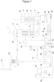
Figure 1 est une vue schématique d'un mode de réalisation d'une section de refroidissement selon l'invention. Ce mode de réalisation n'étant nullement limitatif, on pourra notamment réaliser des variantes de l'invention ne comprenant qu'une sélection de caractéristiques décrites par la suite, telles que décrites ou généralisées, isolées des autres caractéristiques décrites, si cette sélection de caractéristiques est suffisante pour conférer un avantage technique ou pour différencier l'invention par rapport à l'état de la technique. - Il est représenté en
Figure 1 , une section de refroidissement d'une ligne continue de galvanisation comprenant une première partie 2 dans laquelle une bande d'acier 1 en défilement vertical de haut en bas est refroidie par projection d'un liquide selon l'invention. Des buses 3, disposées de part et d'autre de la bande 1, projettent le liquide de refroidissement sur la bande. En amont de ces buses dans un circuit de liquide, un système 4 à membranes permet de retirer l'oxygène dissous dans la solution. En variante, un bullage 31 à l'azote ou un autre gaz neutre est placé dans un bac 13 de projection pour amplifier la désoxygénation naturelle. Une mesure du taux d'oxygène dissous dans la solution est réalisée dans le bac 13 de projection au moyen d'une sonde 35. En sortie de la partie 2, dans le sens de défilement de la bande, se trouve un ensemble 5 de couteaux de liquide destiné à supprimer l'essentiel du liquide de ruissellement présent sur la bande. L'ensemble 5 de couteaux de liquide est suivi, dans le sens de défilement de la bande, par un ensemble 6 de couteaux de gaz destiné à supprimer le liquide encore présent sur la bande. La bande traverse ensuite un bac 7 de renvoi dans le lequel est collecté le liquide de refroidissement projeté par les buses 3 et l'ensemble 5 de couteaux de liquide. Dans ce bac, un second ensemble 8 de couteaux de gaz est destiné à supprimer le liquide encore présent sur la bande. La bande traverse ensuite une partie 9 équipée de tubes chauffants 10 permettant de supprimer toute trace de liquide sur la bande. En sortie de cette partie 9, la bande traverse un sas 11 de séparation d'atmosphère entre les parties humides 2, 7, 9 et des parties 12 situées en aval dans le sens de défilement de la bande. Dans ce sas de séparation d'atmosphère, une injection et/ou une aspiration de gaz permettent de renforcer la séparation d'atmosphères entre les sections en amont et en aval du sas. - Le liquide projeté sur la bande par les buses 3 et l'ensemble 5 de couteaux de liquide est collecté dans le bac 7 de renvoi puis envoyé vers le bac 13 de projection. A cet effet, le liquide est transféré depuis le bac 7 de renvoi dans un bac 27 de recirculation. Ce bac est équipé de compartiments 32 en cascade pour maintenir un maximum de particules dans les premiers compartiments. Des électro-aimants 33 placés sous le bac 27 et un système de tiroirs 34 permettent de récupérer et d'évacuer les particules métalliques sans devoir vidanger le bac. Le liquide passe ensuite dans un ensemble 28 de filtres externes afin d'éliminer les particules métalliques résiduelles avant d'être renvoyé vers le bac 13 de projection au moyen d'une pompe 30. L'ensemble 28 de filtres externes et la pompe 30 sont doublés afin d'assurer la maintenance de ces équipements sans arrêter l'installation.
- Des circuits d'alimentation 14 comprenant une pompe 15 et un échangeur de chaleur 16 permettent d'alimenter les rangées de buses 3 de la partie 2 en liquide de refroidissement à la pression et à la température requises à partir du liquide contenu dans le bac 13 de projection. Les circuits d'alimentation 14 comprennent un circuit 17 de dérivation permettant d'envoyer une partie liquide pompée dans le bac 13 vers un bac 18. En variante, le circuit de dérivation 17 prend sa source dans le bac 27 de recirculation. Le circuit 17 de dérivation est actionné lorsqu'il est nécessaire de renouveler une partie du liquide contenu dans la section de refroidissement afin de maintenir les performances de celui-ci dans la plage de fonctionnement souhaitée.
- Un collecteur 19 de vapeurs est placé dans la partie 2 au-dessus des rangées de buses 3. Les vapeurs collectées sont envoyées vers une tour de lavage (scrubber en anglais) humide 20 dans laquelle les vapeurs sont condensées et envoyées vers le bac 18. En sortie de la tour de lavage, le gaz débarrassé de ses vapeurs est envoyé vers une cheminée 21.
- Le liquide collecté dans le bac 18 est envoyé dans un ensemble de traitement 22 dans lequel la solution usée d'acide formique est dosée avec de l'eau oxygénée afin d'obtenir un mélange d'acide formique et d'hydroxyde de fer III et d'éléments d'alliage de l'acier. Ce mélange est alors filtré par un filtre-presse (non représenté) afin de séparer l'acide formique des hydroxydes de fer III, ces derniers étant évacués par des convoyeurs 23. L'acide formique régénéré est utilisé de nouveau et réinjecté comme solution neuve au moyen d'un circuit 24 dans un bac 25. Un apport en acide formique neuf est également réalisé dans ce bac 25 au moyen d'un circuit 26.
- Le liquide collecté dans le bac 25 peut alors être envoyé dans le bac 13 de projection au moyen d'un circuit 29 comportant une pompe (non numérotée) disposée dans le bac 25.
- Bien sûr, l'invention n'est pas limitée aux exemples qui viennent d'être décrits et de nombreux aménagements peuvent être apportés à ces exemples sans sortir du cadre de l'invention. De plus, les différentes caractéristiques, formes, variantes et modes de réalisation de l'invention peuvent être associés les uns avec les autres selon diverses combinaisons dans la mesure où ils ne sont pas incompatibles ou exclusifs les uns des autres.
Claims (7)
- Procédé de refroidissement d'une bande d'acier (1) en défilement dans une section de refroidissement (2) d'une ligne continue, comprenant une projection sur ladite bande d'acier d'une solution aqueuse à projeter, ladite solution aqueuse à projeter étant une solution liquide ou un mélange d'une solution liquide et d'un gaz, caractérisé en ce que la concentration en acide formique de ladite solution liquide est comprise en 0,1 % et 6 % en masse, en ce que la solution à projeter est projetée sur la bande d'acier par pulvérisation, et en ce que le procédé de refroidissement comporte en outre un contrôle, continu ou périodique, de la solution liquide à projeter, lequel contrôle comprend une mesure d'au moins une donnée physico-chimique de ladite solution choisie dans le groupe comprenant le pH, la densité et la concentration en acide formique, ou une combinaison de ces données physico-chimique, et, lorsque cette mesure n'appartient pas à une plage de tolérance prédéterminée, un volume prédéterminé de la solution liquide à projeter est prélevé et un même volume prédéterminé d'une solution d'acide formique est injecté dans l'unité (13) de projection, ledit volume prédéterminé d'une solution d'acide formique présentant une concentration en acide formique telle que la solution liquide à projeter présente après injection une concentration en acide formique comprise entre 0,1 % à 6 %.
- Procédé selon la revendication 1, dans lequel la solution liquide a une concentration massique en acide formique comprise entre 0,5 % à 2 %.
- Procédé selon la revendication 1 ou 2, dans lequel la concentration massique en acide formique de la solution liquide à projeter après injection est comprise entre 0.5 % à 2 %.
- Procédé selon les revendications 1 à 3, dans lequel la solution prélevée est traitée par oxydation avec de l'eau oxygénée puis filtrée pour en extraire des hydroxydes de fer III et d'autres éléments d'alliage, la solution injectée provenant d'une recirculation de la solution filtrée ou d'une solution neuve.
- Procédé selon l'une des revendications 1 à 4, dans lequel la solution prélevée dans l'unité (13) de recirculation est traitée par désoxygénation avant d'être projetée.
- Procédé selon l'une quelconque des revendications précédentes, comportant en outre une collecte de vapeurs qui résulte de la projection de la solution à projeter sur la bande d'acier, une condensation desdites vapeurs collectées, et une injection de desdites vapeurs condensées dans un circuit de fluide dans lequel est prélevée ladite solution à projeter.
- Dispositif de refroidissement agencé pour refroidir une bande d'acier (1) en défilement dans une section de refroidissement (2) d'une ligne continue comprenant des moyens agencés pour mettre en œuvre un procédé de refroidissement selon l'une quelconque des revendications précédentes par projection sur ladite bande d'acier d'une solution aqueuse, ladite solution aqueuse étant une solution liquide ou un mélange d'une solution liquide et d'un gaz, la concentration en acide formique de ladite solution aqueuse étant comprise en 0,1 % et 6 % en masse, le dispositif comportant un système de membranes (4) agencé pour désoxygéner ladite solution, les membranes sont balayées d'azote d'un côté avec un tirage au vide de l'autre.
Priority Applications (2)
| Application Number | Priority Date | Filing Date | Title |
|---|---|---|---|
| RS20210951A RS62170B2 (sr) | 2017-03-22 | 2018-03-22 | Metoda i uređaj za hlađenje pokretne čelične trake u sekciji za hlađenje neprekidne linije |
| PL18715224.4T PL3601623T5 (pl) | 2017-03-22 | 2018-03-22 | Sposób i urządzenie do schładzania taśmy stalowej przesuwającej się w sekcji schładzania linii ciągłej |
Applications Claiming Priority (2)
| Application Number | Priority Date | Filing Date | Title |
|---|---|---|---|
| FR1752352A FR3064279B1 (fr) | 2017-03-22 | 2017-03-22 | Procede et dispositif de refroidissement d'une bande d'acier en defilement dans une section de refroidissement d'une ligne continue |
| PCT/FR2018/050705 WO2018172713A1 (fr) | 2017-03-22 | 2018-03-22 | Procede et dispositif de refroidissement d'une bande d'acier en defilement dans une section de refroidissement d'une ligne continue |
Publications (3)
| Publication Number | Publication Date |
|---|---|
| EP3601623A1 EP3601623A1 (fr) | 2020-02-05 |
| EP3601623B1 EP3601623B1 (fr) | 2021-04-28 |
| EP3601623B2 true EP3601623B2 (fr) | 2025-03-26 |
Family
ID=58739209
Family Applications (1)
| Application Number | Title | Priority Date | Filing Date |
|---|---|---|---|
| EP18715224.4A Active EP3601623B2 (fr) | 2017-03-22 | 2018-03-22 | Procédé et dispositif de refroidissement d'une bande d'acier en defilement dans une section de refroidissement d'une ligne continue |
Country Status (12)
| Country | Link |
|---|---|
| US (1) | US11162156B2 (fr) |
| EP (1) | EP3601623B2 (fr) |
| JP (2) | JP2020520409A (fr) |
| KR (2) | KR102556572B1 (fr) |
| CN (1) | CN110546283A (fr) |
| ES (1) | ES2882291T5 (fr) |
| FI (1) | FI3601623T4 (fr) |
| FR (1) | FR3064279B1 (fr) |
| PL (1) | PL3601623T5 (fr) |
| PT (1) | PT3601623T (fr) |
| RS (1) | RS62170B2 (fr) |
| WO (1) | WO2018172713A1 (fr) |
Families Citing this family (5)
| Publication number | Priority date | Publication date | Assignee | Title |
|---|---|---|---|---|
| FR3064279B1 (fr) * | 2017-03-22 | 2020-06-26 | Fives Stein | Procede et dispositif de refroidissement d'une bande d'acier en defilement dans une section de refroidissement d'une ligne continue |
| FR3104178B1 (fr) | 2019-12-09 | 2022-12-02 | Fives Stein | Dispositif et procede de traitement thermique des aciers comprenant un refroidissement humide |
| CN111304424A (zh) * | 2020-04-27 | 2020-06-19 | 唐山曹妃甸区首燕机械有限公司 | 一种炉鼻子加湿器 |
| CN113604635B (zh) * | 2021-07-27 | 2023-05-09 | 中国华电科工集团有限公司 | 一种用于太阳能集热器制造系统的回火设备及其回火方法 |
| FR3156805B1 (fr) | 2023-12-13 | 2025-11-07 | Fives Stein | Ligne de galvanisation a refroidissement humide |
Citations (5)
| Publication number | Priority date | Publication date | Assignee | Title |
|---|---|---|---|---|
| FR2439825B1 (fr) † | 1978-10-27 | 1984-03-09 | Centre Rech Metallurgique | |
| LU85333A1 (fr) † | 1984-04-24 | 1985-11-27 | Centre Rech Metallurgique | Procede de protection d'un produit metallique contre l'oxydation pendant la trempe |
| WO2006112109A1 (fr) † | 2005-04-12 | 2006-10-26 | Nippon Steel Corporation | Processus pour le refroidissement d'une bande d'acier dans la zone de refroidissement d'un equipement de traitement thermique continu, et appareil de refroidissement |
| WO2013136734A1 (fr) † | 2012-03-12 | 2013-09-19 | Jfeスチール株式会社 | Système de détartrage |
| WO2014059475A1 (fr) † | 2012-10-17 | 2014-04-24 | Bluescope Steel Limited | Procédé de fabrication de bande d'acier revêtue de métal |
Family Cites Families (16)
| Publication number | Priority date | Publication date | Assignee | Title |
|---|---|---|---|---|
| US3729417A (en) * | 1969-02-14 | 1973-04-24 | Toyota Motor Co Ltd | Quenching oil compositions |
| GB1530859A (en) * | 1976-06-23 | 1978-11-01 | Centre Rech Metallurgique | Continuous heat-treatment of steel strip |
| JPS5511155A (en) * | 1978-07-10 | 1980-01-25 | Nippon Steel Corp | Continuous annealing process for cold rolled hoop |
| BE880587A (fr) * | 1979-12-12 | 1980-06-12 | Centre Rech Metallurgique | Installation de traitement thermique en continu de toles d'acier |
| JPS6052531A (ja) * | 1983-09-02 | 1985-03-25 | Nippon Steel Corp | 冷延鋼帯の冷却用水溶液 |
| JPS63192820A (ja) * | 1987-02-06 | 1988-08-10 | Sumitomo Metal Ind Ltd | 鋼材の冷却方法 |
| JPH02170925A (ja) * | 1988-12-21 | 1990-07-02 | Sumitomo Metal Ind Ltd | 連続焼鈍冷間圧延鋼板の製造方法 |
| BE1012753A3 (fr) | 1998-10-01 | 2001-03-06 | Centre Rech Metallurgique | Procede pour le refroidissement non oxydant d'une bande d'acier laminee. |
| JP5086545B2 (ja) * | 2005-04-12 | 2012-11-28 | 新日鉄エンジニアリング株式会社 | 連続熱処理設備の冷却帯における鋼帯の冷却装置 |
| FR2942629B1 (fr) | 2009-03-02 | 2011-11-04 | Cmi Thermline Services | Procede de refroidissement d'une bande metallique circulant dans une section de refroidissement d'une ligne de traitement thermique en continu, et installation de mise en oeuvre dudit procede |
| JP6227248B2 (ja) * | 2012-12-27 | 2017-11-08 | 出光興産株式会社 | 水系冷却剤 |
| FR3014447B1 (fr) * | 2013-12-05 | 2016-02-05 | Fives Stein | Procede et installation de traitement thermique en continu d'une bande d'acier |
| JP6414739B2 (ja) * | 2014-10-14 | 2018-10-31 | 住友電工ウインテック株式会社 | 導体軟化処理装置及び導体軟化処理方法 |
| CN204999977U (zh) | 2015-10-12 | 2016-01-27 | 中钢集团郑州金属制品研究院有限公司 | 钢丝水浴索氏体化热处理超声波清洗作业线 |
| FR3064278B1 (fr) * | 2017-03-22 | 2021-04-23 | Fives Stein | Section et procede de refroidissement d'une ligne continue combinant un refroidissement sec et un refroidissement humide |
| FR3064279B1 (fr) * | 2017-03-22 | 2020-06-26 | Fives Stein | Procede et dispositif de refroidissement d'une bande d'acier en defilement dans une section de refroidissement d'une ligne continue |
-
2017
- 2017-03-22 FR FR1752352A patent/FR3064279B1/fr active Active
-
2018
- 2018-03-22 JP JP2019551699A patent/JP2020520409A/ja active Pending
- 2018-03-22 US US16/496,221 patent/US11162156B2/en active Active
- 2018-03-22 FI FIEP18715224.4T patent/FI3601623T4/en active
- 2018-03-22 KR KR1020197030732A patent/KR102556572B1/ko active Active
- 2018-03-22 PL PL18715224.4T patent/PL3601623T5/pl unknown
- 2018-03-22 CN CN201880019710.5A patent/CN110546283A/zh active Pending
- 2018-03-22 RS RS20210951A patent/RS62170B2/sr unknown
- 2018-03-22 ES ES18715224T patent/ES2882291T5/es active Active
- 2018-03-22 EP EP18715224.4A patent/EP3601623B2/fr active Active
- 2018-03-22 KR KR1020237014679A patent/KR20230065369A/ko not_active Ceased
- 2018-03-22 PT PT187152244T patent/PT3601623T/pt unknown
- 2018-03-22 WO PCT/FR2018/050705 patent/WO2018172713A1/fr not_active Ceased
-
2022
- 2022-08-01 JP JP2022122552A patent/JP7422822B2/ja active Active
Patent Citations (5)
| Publication number | Priority date | Publication date | Assignee | Title |
|---|---|---|---|---|
| FR2439825B1 (fr) † | 1978-10-27 | 1984-03-09 | Centre Rech Metallurgique | |
| LU85333A1 (fr) † | 1984-04-24 | 1985-11-27 | Centre Rech Metallurgique | Procede de protection d'un produit metallique contre l'oxydation pendant la trempe |
| WO2006112109A1 (fr) † | 2005-04-12 | 2006-10-26 | Nippon Steel Corporation | Processus pour le refroidissement d'une bande d'acier dans la zone de refroidissement d'un equipement de traitement thermique continu, et appareil de refroidissement |
| WO2013136734A1 (fr) † | 2012-03-12 | 2013-09-19 | Jfeスチール株式会社 | Système de détartrage |
| WO2014059475A1 (fr) † | 2012-10-17 | 2014-04-24 | Bluescope Steel Limited | Procédé de fabrication de bande d'acier revêtue de métal |
Also Published As
| Publication number | Publication date |
|---|---|
| ES2882291T3 (es) | 2021-12-01 |
| FI3601623T4 (en) | 2025-05-20 |
| ES2882291T5 (en) | 2025-07-11 |
| KR20230065369A (ko) | 2023-05-11 |
| PT3601623T (pt) | 2021-07-26 |
| RS62170B1 (sr) | 2021-08-31 |
| PL3601623T5 (pl) | 2025-06-30 |
| US20200017934A1 (en) | 2020-01-16 |
| CN110546283A (zh) | 2019-12-06 |
| FR3064279A1 (fr) | 2018-09-28 |
| FR3064279B1 (fr) | 2020-06-26 |
| JP2020520409A (ja) | 2020-07-09 |
| KR20190132430A (ko) | 2019-11-27 |
| US11162156B2 (en) | 2021-11-02 |
| EP3601623A1 (fr) | 2020-02-05 |
| WO2018172713A1 (fr) | 2018-09-27 |
| JP7422822B2 (ja) | 2024-01-26 |
| EP3601623B1 (fr) | 2021-04-28 |
| PL3601623T3 (pl) | 2021-11-02 |
| JP2022163112A (ja) | 2022-10-25 |
| KR102556572B1 (ko) | 2023-07-18 |
| RS62170B2 (sr) | 2025-07-31 |
Similar Documents
| Publication | Publication Date | Title |
|---|---|---|
| EP3601623B2 (fr) | Procédé et dispositif de refroidissement d'une bande d'acier en defilement dans une section de refroidissement d'une ligne continue | |
| EP1450934B1 (fr) | Procede pour le traitement de gaz effluent contenant des hydrocarbures | |
| FR2946665A1 (fr) | Systeme et procede de traitement des fumees et gaz produits par une cuve d'electrolyse lors de la fabrication d'aluminium | |
| EP0252836B1 (fr) | Procédé pour l'élimination rapide de l'hydrogène sulfuré contenu dans le soufre liquide et système catalytique utilisable pour sa mise en oeuvre | |
| EP1262231B1 (fr) | Procédé d'élimination sélective des composés organiques fonctionnalisés d'un milieu liquide | |
| EP0766751B1 (fr) | Procede de decapage de materiaux metalliques | |
| EP1633499B1 (fr) | Procede de traitement de surface ecologique d'un conteneur metallique, associant une action chimique et une action mecanique | |
| FR2551465A3 (fr) | Procede de decapage acide des aciers inoxydables et solution acide pour sa mise en oeuvre | |
| CA2764724C (fr) | Systeme et procede de recuperation d'energie | |
| EP4370719B1 (fr) | Refroidissement liquide d'une bande en defilement dans une ligne continue | |
| EP0844292B1 (fr) | Composition et son utilisation pour convertir un gaz contenant de l'hydrogène sulfuré et de l'anhydride sulfureux en soufre | |
| EP4073292A1 (fr) | Dispositif et procédé de traitement thermique des aciers comprenant un refroidissement humide | |
| FR3019367A1 (fr) | ||
| EP0084478A2 (fr) | Procédé de régénération en continu de bains de fluxage dans la galvanisation au trempé de pièces en acier | |
| BE1015893A3 (fr) | Procede de controle du decapage des metaux. | |
| JP6836026B2 (ja) | 浸炭装置 | |
| FR2641219A1 (fr) | Procede et appareil pour recuperer et reutiliser des vapeurs organiques produites pendant le laminage et le decapage d'une barre et d'une tige de cuivre coulees | |
| WO1999043006A1 (fr) | Procede et installation de decontamination de surfaces metalliques | |
| FR3011748A1 (fr) | Procede et dispositif de pretraitement de vapeurs d'hydrocarbures lourds en amont d'une unite de traitement final | |
| WO2007055670A1 (fr) | Procede de recyclage de solution de gravure pour le traitement des cartes imprimees | |
| FR2874220A1 (fr) | Procede de regeneration des acides d'usinage chimique, installation pour la mise en oeuvre du procede et procede d'usinage chimique associe. | |
| BE530473A (fr) | ||
| FR3037505A1 (fr) | Procede et installation de recuperation d'hydrocarbures utilisant des fumees industrielles riches en co2 |
Legal Events
| Date | Code | Title | Description |
|---|---|---|---|
| STAA | Information on the status of an ep patent application or granted ep patent |
Free format text: STATUS: UNKNOWN |
|
| STAA | Information on the status of an ep patent application or granted ep patent |
Free format text: STATUS: THE INTERNATIONAL PUBLICATION HAS BEEN MADE |
|
| PUAI | Public reference made under article 153(3) epc to a published international application that has entered the european phase |
Free format text: ORIGINAL CODE: 0009012 |
|
| STAA | Information on the status of an ep patent application or granted ep patent |
Free format text: STATUS: REQUEST FOR EXAMINATION WAS MADE |
|
| 17P | Request for examination filed |
Effective date: 20190918 |
|
| AK | Designated contracting states |
Kind code of ref document: A1 Designated state(s): AL AT BE BG CH CY CZ DE DK EE ES FI FR GB GR HR HU IE IS IT LI LT LU LV MC MK MT NL NO PL PT RO RS SE SI SK SM TR |
|
| AX | Request for extension of the european patent |
Extension state: BA ME |
|
| RIN1 | Information on inventor provided before grant (corrected) |
Inventor name: MAGADOUX, ERIC |
|
| DAV | Request for validation of the european patent (deleted) | ||
| DAX | Request for extension of the european patent (deleted) | ||
| STAA | Information on the status of an ep patent application or granted ep patent |
Free format text: STATUS: EXAMINATION IS IN PROGRESS |
|
| 17Q | First examination report despatched |
Effective date: 20200907 |
|
| TPAC | Observations filed by third parties |
Free format text: ORIGINAL CODE: EPIDOSNTIPA |
|
| GRAP | Despatch of communication of intention to grant a patent |
Free format text: ORIGINAL CODE: EPIDOSNIGR1 |
|
| STAA | Information on the status of an ep patent application or granted ep patent |
Free format text: STATUS: GRANT OF PATENT IS INTENDED |
|
| INTG | Intention to grant announced |
Effective date: 20210113 |
|
| GRAS | Grant fee paid |
Free format text: ORIGINAL CODE: EPIDOSNIGR3 |
|
| GRAA | (expected) grant |
Free format text: ORIGINAL CODE: 0009210 |
|
| STAA | Information on the status of an ep patent application or granted ep patent |
Free format text: STATUS: THE PATENT HAS BEEN GRANTED |
|
| AK | Designated contracting states |
Kind code of ref document: B1 Designated state(s): AL AT BE BG CH CY CZ DE DK EE ES FI FR GB GR HR HU IE IS IT LI LT LU LV MC MK MT NL NO PL PT RO RS SE SI SK SM TR |
|
| REG | Reference to a national code |
Ref country code: GB Ref legal event code: FG4D Free format text: NOT ENGLISH |
|
| REG | Reference to a national code |
Ref country code: CH Ref legal event code: EP |
|
| REG | Reference to a national code |
Ref country code: AT Ref legal event code: REF Ref document number: 1387108 Country of ref document: AT Kind code of ref document: T Effective date: 20210515 |
|
| REG | Reference to a national code |
Ref country code: DE Ref legal event code: R096 Ref document number: 602018016228 Country of ref document: DE |
|
| REG | Reference to a national code |
Ref country code: IE Ref legal event code: FG4D Free format text: LANGUAGE OF EP DOCUMENT: FRENCH |
|
| REG | Reference to a national code |
Ref country code: PT Ref legal event code: SC4A Ref document number: 3601623 Country of ref document: PT Date of ref document: 20210726 Kind code of ref document: T Free format text: AVAILABILITY OF NATIONAL TRANSLATION Effective date: 20210721 |
|
| REG | Reference to a national code |
Ref country code: FI Ref legal event code: FGE |
|
| REG | Reference to a national code |
Ref country code: NL Ref legal event code: FP |
|
| REG | Reference to a national code |
Ref country code: SE Ref legal event code: TRGR |
|
| REG | Reference to a national code |
Ref country code: LT Ref legal event code: MG9D |
|
| REG | Reference to a national code |
Ref country code: SK Ref legal event code: T3 Ref document number: E 37787 Country of ref document: SK |
|
| PG25 | Lapsed in a contracting state [announced via postgrant information from national office to epo] |
Ref country code: HR Free format text: LAPSE BECAUSE OF FAILURE TO SUBMIT A TRANSLATION OF THE DESCRIPTION OR TO PAY THE FEE WITHIN THE PRESCRIBED TIME-LIMIT Effective date: 20210428 Ref country code: LT Free format text: LAPSE BECAUSE OF FAILURE TO SUBMIT A TRANSLATION OF THE DESCRIPTION OR TO PAY THE FEE WITHIN THE PRESCRIBED TIME-LIMIT Effective date: 20210428 Ref country code: BG Free format text: LAPSE BECAUSE OF FAILURE TO SUBMIT A TRANSLATION OF THE DESCRIPTION OR TO PAY THE FEE WITHIN THE PRESCRIBED TIME-LIMIT Effective date: 20210728 |
|
| PG25 | Lapsed in a contracting state [announced via postgrant information from national office to epo] |
Ref country code: GR Free format text: LAPSE BECAUSE OF FAILURE TO SUBMIT A TRANSLATION OF THE DESCRIPTION OR TO PAY THE FEE WITHIN THE PRESCRIBED TIME-LIMIT Effective date: 20210729 Ref country code: IS Free format text: LAPSE BECAUSE OF FAILURE TO SUBMIT A TRANSLATION OF THE DESCRIPTION OR TO PAY THE FEE WITHIN THE PRESCRIBED TIME-LIMIT Effective date: 20210828 Ref country code: LV Free format text: LAPSE BECAUSE OF FAILURE TO SUBMIT A TRANSLATION OF THE DESCRIPTION OR TO PAY THE FEE WITHIN THE PRESCRIBED TIME-LIMIT Effective date: 20210428 Ref country code: NO Free format text: LAPSE BECAUSE OF FAILURE TO SUBMIT A TRANSLATION OF THE DESCRIPTION OR TO PAY THE FEE WITHIN THE PRESCRIBED TIME-LIMIT Effective date: 20210728 |
|
| REG | Reference to a national code |
Ref country code: ES Ref legal event code: FG2A Ref document number: 2882291 Country of ref document: ES Kind code of ref document: T3 Effective date: 20211201 |
|
| REG | Reference to a national code |
Ref country code: DE Ref legal event code: R026 Ref document number: 602018016228 Country of ref document: DE |
|
| PG25 | Lapsed in a contracting state [announced via postgrant information from national office to epo] |
Ref country code: RO Free format text: LAPSE BECAUSE OF FAILURE TO SUBMIT A TRANSLATION OF THE DESCRIPTION OR TO PAY THE FEE WITHIN THE PRESCRIBED TIME-LIMIT Effective date: 20210428 Ref country code: DK Free format text: LAPSE BECAUSE OF FAILURE TO SUBMIT A TRANSLATION OF THE DESCRIPTION OR TO PAY THE FEE WITHIN THE PRESCRIBED TIME-LIMIT Effective date: 20210428 Ref country code: SM Free format text: LAPSE BECAUSE OF FAILURE TO SUBMIT A TRANSLATION OF THE DESCRIPTION OR TO PAY THE FEE WITHIN THE PRESCRIBED TIME-LIMIT Effective date: 20210428 Ref country code: EE Free format text: LAPSE BECAUSE OF FAILURE TO SUBMIT A TRANSLATION OF THE DESCRIPTION OR TO PAY THE FEE WITHIN THE PRESCRIBED TIME-LIMIT Effective date: 20210428 |
|
| PLBI | Opposition filed |
Free format text: ORIGINAL CODE: 0009260 |
|
| PLAX | Notice of opposition and request to file observation + time limit sent |
Free format text: ORIGINAL CODE: EPIDOSNOBS2 |
|
| REG | Reference to a national code |
Ref country code: FI Ref legal event code: MDE Opponent name: DREVER INTERNATIONAL |
|
| 26 | Opposition filed |
Opponent name: DREVER INTERNATIONAL Effective date: 20220128 |
|
| PG25 | Lapsed in a contracting state [announced via postgrant information from national office to epo] |
Ref country code: IS Free format text: LAPSE BECAUSE OF FAILURE TO SUBMIT A TRANSLATION OF THE DESCRIPTION OR TO PAY THE FEE WITHIN THE PRESCRIBED TIME-LIMIT Effective date: 20210828 Ref country code: AL Free format text: LAPSE BECAUSE OF FAILURE TO SUBMIT A TRANSLATION OF THE DESCRIPTION OR TO PAY THE FEE WITHIN THE PRESCRIBED TIME-LIMIT Effective date: 20210428 |
|
| PLBB | Reply of patent proprietor to notice(s) of opposition received |
Free format text: ORIGINAL CODE: EPIDOSNOBS3 |
|
| PG25 | Lapsed in a contracting state [announced via postgrant information from national office to epo] |
Ref country code: MC Free format text: LAPSE BECAUSE OF FAILURE TO SUBMIT A TRANSLATION OF THE DESCRIPTION OR TO PAY THE FEE WITHIN THE PRESCRIBED TIME-LIMIT Effective date: 20210428 |
|
| REG | Reference to a national code |
Ref country code: CH Ref legal event code: PL |
|
| PG25 | Lapsed in a contracting state [announced via postgrant information from national office to epo] |
Ref country code: LI Free format text: LAPSE BECAUSE OF NON-PAYMENT OF DUE FEES Effective date: 20220331 Ref country code: IE Free format text: LAPSE BECAUSE OF NON-PAYMENT OF DUE FEES Effective date: 20220322 Ref country code: CH Free format text: LAPSE BECAUSE OF NON-PAYMENT OF DUE FEES Effective date: 20220331 |
|
| PG25 | Lapsed in a contracting state [announced via postgrant information from national office to epo] |
Ref country code: MK Free format text: LAPSE BECAUSE OF FAILURE TO SUBMIT A TRANSLATION OF THE DESCRIPTION OR TO PAY THE FEE WITHIN THE PRESCRIBED TIME-LIMIT Effective date: 20210428 Ref country code: CY Free format text: LAPSE BECAUSE OF FAILURE TO SUBMIT A TRANSLATION OF THE DESCRIPTION OR TO PAY THE FEE WITHIN THE PRESCRIBED TIME-LIMIT Effective date: 20210428 |
|
| APBP | Date of receipt of notice of appeal recorded |
Free format text: ORIGINAL CODE: EPIDOSNNOA2O |
|
| APAH | Appeal reference modified |
Free format text: ORIGINAL CODE: EPIDOSCREFNO |
|
| APAW | Appeal reference deleted |
Free format text: ORIGINAL CODE: EPIDOSDREFNO |
|
| PG25 | Lapsed in a contracting state [announced via postgrant information from national office to epo] |
Ref country code: HU Free format text: LAPSE BECAUSE OF FAILURE TO SUBMIT A TRANSLATION OF THE DESCRIPTION OR TO PAY THE FEE WITHIN THE PRESCRIBED TIME-LIMIT; INVALID AB INITIO Effective date: 20180322 |
|
| APBU | Appeal procedure closed |
Free format text: ORIGINAL CODE: EPIDOSNNOA9O |
|
| REG | Reference to a national code |
Ref country code: CH Ref legal event code: PK Free format text: TITRE |
|
| PG25 | Lapsed in a contracting state [announced via postgrant information from national office to epo] |
Ref country code: MT Free format text: LAPSE BECAUSE OF FAILURE TO SUBMIT A TRANSLATION OF THE DESCRIPTION OR TO PAY THE FEE WITHIN THE PRESCRIBED TIME-LIMIT Effective date: 20210428 |
|
| PUAH | Patent maintained in amended form |
Free format text: ORIGINAL CODE: 0009272 |
|
| STAA | Information on the status of an ep patent application or granted ep patent |
Free format text: STATUS: PATENT MAINTAINED AS AMENDED |
|
| 27A | Patent maintained in amended form |
Effective date: 20250326 |
|
| AK | Designated contracting states |
Kind code of ref document: B2 Designated state(s): AL AT BE BG CH CY CZ DE DK EE ES FI FR GB GR HR HU IE IS IT LI LT LU LV MC MK MT NL NO PL PT RO RS SE SI SK SM TR |
|
| REG | Reference to a national code |
Ref country code: DE Ref legal event code: R102 Ref document number: 602018016228 Country of ref document: DE |
|
| REG | Reference to a national code |
Ref country code: NL Ref legal event code: FP |
|
| REG | Reference to a national code |
Ref country code: SE Ref legal event code: RPEO |
|
| REG | Reference to a national code |
Ref country code: SK Ref legal event code: T5 Ref document number: E 37787 Country of ref document: SK |
|
| PGFP | Annual fee paid to national office [announced via postgrant information from national office to epo] |
Ref country code: ES Payment date: 20250402 Year of fee payment: 8 |
|
| REG | Reference to a national code |
Ref country code: ES Ref legal event code: DC2A Ref document number: 2882291 Country of ref document: ES Kind code of ref document: T5 Effective date: 20250711 |
|
| PGFP | Annual fee paid to national office [announced via postgrant information from national office to epo] |
Ref country code: LU Payment date: 20260219 Year of fee payment: 9 Ref country code: NL Payment date: 20260219 Year of fee payment: 9 |
|
| PGFP | Annual fee paid to national office [announced via postgrant information from national office to epo] |
Ref country code: SE Payment date: 20260219 Year of fee payment: 9 |
|
| PGFP | Annual fee paid to national office [announced via postgrant information from national office to epo] |
Ref country code: GB Payment date: 20260220 Year of fee payment: 9 |
|
| PGFP | Annual fee paid to national office [announced via postgrant information from national office to epo] |
Ref country code: DE Payment date: 20260219 Year of fee payment: 9 |
|
| PGFP | Annual fee paid to national office [announced via postgrant information from national office to epo] |
Ref country code: AT Payment date: 20260223 Year of fee payment: 9 |
|
| PGFP | Annual fee paid to national office [announced via postgrant information from national office to epo] |
Ref country code: FI Payment date: 20260219 Year of fee payment: 9 Ref country code: BE Payment date: 20260219 Year of fee payment: 9 Ref country code: IT Payment date: 20260219 Year of fee payment: 9 |
|
| PGFP | Annual fee paid to national office [announced via postgrant information from national office to epo] |
Ref country code: RS Payment date: 20260319 Year of fee payment: 9 |
|
| PGFP | Annual fee paid to national office [announced via postgrant information from national office to epo] |
Ref country code: FR Payment date: 20260220 Year of fee payment: 9 |
|
| PGFP | Annual fee paid to national office [announced via postgrant information from national office to epo] |
Ref country code: TR Payment date: 20260225 Year of fee payment: 9 |
|
| PGFP | Annual fee paid to national office [announced via postgrant information from national office to epo] |
Ref country code: PT Payment date: 20260220 Year of fee payment: 9 Ref country code: CZ Payment date: 20260302 Year of fee payment: 9 |
|
| PGFP | Annual fee paid to national office [announced via postgrant information from national office to epo] |
Ref country code: PL Payment date: 20260220 Year of fee payment: 9 |
|
| PGFP | Annual fee paid to national office [announced via postgrant information from national office to epo] |
Ref country code: SK Payment date: 20260226 Year of fee payment: 9 |