EP3601002B1 - Berührungssensorsysteme und verfahren für fahrzeuge - Google Patents
Berührungssensorsysteme und verfahren für fahrzeuge Download PDFInfo
- Publication number
- EP3601002B1 EP3601002B1 EP18771699.8A EP18771699A EP3601002B1 EP 3601002 B1 EP3601002 B1 EP 3601002B1 EP 18771699 A EP18771699 A EP 18771699A EP 3601002 B1 EP3601002 B1 EP 3601002B1
- Authority
- EP
- European Patent Office
- Prior art keywords
- steering wheel
- vehicle
- driver
- gesture
- touch
- Prior art date
- Legal status (The legal status is an assumption and is not a legal conclusion. Google has not performed a legal analysis and makes no representation as to the accuracy of the status listed.)
- Active
Links
Images


Classifications
-
- B—PERFORMING OPERATIONS; TRANSPORTING
- B60—VEHICLES IN GENERAL
- B60W—CONJOINT CONTROL OF VEHICLE SUB-UNITS OF DIFFERENT TYPE OR DIFFERENT FUNCTION; CONTROL SYSTEMS SPECIALLY ADAPTED FOR HYBRID VEHICLES; ROAD VEHICLE DRIVE CONTROL SYSTEMS FOR PURPOSES NOT RELATED TO THE CONTROL OF A PARTICULAR SUB-UNIT
- B60W40/00—Estimation or calculation of non-directly measurable driving parameters for road vehicle drive control systems not related to the control of a particular sub unit, e.g. by using mathematical models
- B60W40/08—Estimation or calculation of non-directly measurable driving parameters for road vehicle drive control systems not related to the control of a particular sub unit, e.g. by using mathematical models related to drivers or passengers
-
- B—PERFORMING OPERATIONS; TRANSPORTING
- B60—VEHICLES IN GENERAL
- B60K—ARRANGEMENT OR MOUNTING OF PROPULSION UNITS OR OF TRANSMISSIONS IN VEHICLES; ARRANGEMENT OR MOUNTING OF PLURAL DIVERSE PRIME-MOVERS IN VEHICLES; AUXILIARY DRIVES FOR VEHICLES; INSTRUMENTATION OR DASHBOARDS FOR VEHICLES; ARRANGEMENTS IN CONNECTION WITH COOLING, AIR INTAKE, GAS EXHAUST OR FUEL SUPPLY OF PROPULSION UNITS IN VEHICLES
- B60K35/00—Instruments specially adapted for vehicles; Arrangement of instruments in or on vehicles
- B60K35/20—Output arrangements, i.e. from vehicle to user, associated with vehicle functions or specially adapted therefor
- B60K35/26—Output arrangements, i.e. from vehicle to user, associated with vehicle functions or specially adapted therefor using acoustic output
-
- A—HUMAN NECESSITIES
- A61—MEDICAL OR VETERINARY SCIENCE; HYGIENE
- A61B—DIAGNOSIS; SURGERY; IDENTIFICATION
- A61B5/00—Measuring for diagnostic purposes; Identification of persons
- A61B5/02—Detecting, measuring or recording for evaluating the cardiovascular system, e.g. pulse, heart rate, blood pressure or blood flow
- A61B5/026—Measuring blood flow
- A61B5/0261—Measuring blood flow using optical means, e.g. infrared light
-
- A—HUMAN NECESSITIES
- A61—MEDICAL OR VETERINARY SCIENCE; HYGIENE
- A61B—DIAGNOSIS; SURGERY; IDENTIFICATION
- A61B5/00—Measuring for diagnostic purposes; Identification of persons
- A61B5/02—Detecting, measuring or recording for evaluating the cardiovascular system, e.g. pulse, heart rate, blood pressure or blood flow
- A61B5/026—Measuring blood flow
- A61B5/0295—Measuring blood flow using plethysmography, i.e. measuring the variations in the volume of a body part as modified by the circulation of blood therethrough, e.g. impedance plethysmography
-
- A—HUMAN NECESSITIES
- A61—MEDICAL OR VETERINARY SCIENCE; HYGIENE
- A61B—DIAGNOSIS; SURGERY; IDENTIFICATION
- A61B5/00—Measuring for diagnostic purposes; Identification of persons
- A61B5/16—Devices for psychotechnics; Testing reaction times ; Devices for evaluating the psychological state
- A61B5/18—Devices for psychotechnics; Testing reaction times ; Devices for evaluating the psychological state for vehicle drivers or machine operators
-
- A—HUMAN NECESSITIES
- A61—MEDICAL OR VETERINARY SCIENCE; HYGIENE
- A61B—DIAGNOSIS; SURGERY; IDENTIFICATION
- A61B5/00—Measuring for diagnostic purposes; Identification of persons
- A61B5/68—Arrangements of detecting, measuring or recording means, e.g. sensors, in relation to patient
- A61B5/6887—Arrangements of detecting, measuring or recording means, e.g. sensors, in relation to patient mounted on external non-worn devices, e.g. non-medical devices
- A61B5/6893—Cars
-
- B—PERFORMING OPERATIONS; TRANSPORTING
- B60—VEHICLES IN GENERAL
- B60K—ARRANGEMENT OR MOUNTING OF PROPULSION UNITS OR OF TRANSMISSIONS IN VEHICLES; ARRANGEMENT OR MOUNTING OF PLURAL DIVERSE PRIME-MOVERS IN VEHICLES; AUXILIARY DRIVES FOR VEHICLES; INSTRUMENTATION OR DASHBOARDS FOR VEHICLES; ARRANGEMENTS IN CONNECTION WITH COOLING, AIR INTAKE, GAS EXHAUST OR FUEL SUPPLY OF PROPULSION UNITS IN VEHICLES
- B60K35/00—Instruments specially adapted for vehicles; Arrangement of instruments in or on vehicles
- B60K35/10—Input arrangements, i.e. from user to vehicle, associated with vehicle functions or specially adapted therefor
-
- B—PERFORMING OPERATIONS; TRANSPORTING
- B60—VEHICLES IN GENERAL
- B60K—ARRANGEMENT OR MOUNTING OF PROPULSION UNITS OR OF TRANSMISSIONS IN VEHICLES; ARRANGEMENT OR MOUNTING OF PLURAL DIVERSE PRIME-MOVERS IN VEHICLES; AUXILIARY DRIVES FOR VEHICLES; INSTRUMENTATION OR DASHBOARDS FOR VEHICLES; ARRANGEMENTS IN CONNECTION WITH COOLING, AIR INTAKE, GAS EXHAUST OR FUEL SUPPLY OF PROPULSION UNITS IN VEHICLES
- B60K35/00—Instruments specially adapted for vehicles; Arrangement of instruments in or on vehicles
- B60K35/20—Output arrangements, i.e. from vehicle to user, associated with vehicle functions or specially adapted therefor
- B60K35/21—Output arrangements, i.e. from vehicle to user, associated with vehicle functions or specially adapted therefor using visual output, e.g. blinking lights or matrix displays
- B60K35/212—Output arrangements, i.e. from vehicle to user, associated with vehicle functions or specially adapted therefor using visual output, e.g. blinking lights or matrix displays displaying on manual operation elements, e.g. on a knob
-
- B—PERFORMING OPERATIONS; TRANSPORTING
- B60—VEHICLES IN GENERAL
- B60K—ARRANGEMENT OR MOUNTING OF PROPULSION UNITS OR OF TRANSMISSIONS IN VEHICLES; ARRANGEMENT OR MOUNTING OF PLURAL DIVERSE PRIME-MOVERS IN VEHICLES; AUXILIARY DRIVES FOR VEHICLES; INSTRUMENTATION OR DASHBOARDS FOR VEHICLES; ARRANGEMENTS IN CONNECTION WITH COOLING, AIR INTAKE, GAS EXHAUST OR FUEL SUPPLY OF PROPULSION UNITS IN VEHICLES
- B60K35/00—Instruments specially adapted for vehicles; Arrangement of instruments in or on vehicles
- B60K35/20—Output arrangements, i.e. from vehicle to user, associated with vehicle functions or specially adapted therefor
- B60K35/21—Output arrangements, i.e. from vehicle to user, associated with vehicle functions or specially adapted therefor using visual output, e.g. blinking lights or matrix displays
- B60K35/22—Display screens
-
- B—PERFORMING OPERATIONS; TRANSPORTING
- B60—VEHICLES IN GENERAL
- B60K—ARRANGEMENT OR MOUNTING OF PROPULSION UNITS OR OF TRANSMISSIONS IN VEHICLES; ARRANGEMENT OR MOUNTING OF PLURAL DIVERSE PRIME-MOVERS IN VEHICLES; AUXILIARY DRIVES FOR VEHICLES; INSTRUMENTATION OR DASHBOARDS FOR VEHICLES; ARRANGEMENTS IN CONNECTION WITH COOLING, AIR INTAKE, GAS EXHAUST OR FUEL SUPPLY OF PROPULSION UNITS IN VEHICLES
- B60K35/00—Instruments specially adapted for vehicles; Arrangement of instruments in or on vehicles
- B60K35/60—Instruments characterised by their location or relative disposition in or on vehicles
-
- B—PERFORMING OPERATIONS; TRANSPORTING
- B60—VEHICLES IN GENERAL
- B60W—CONJOINT CONTROL OF VEHICLE SUB-UNITS OF DIFFERENT TYPE OR DIFFERENT FUNCTION; CONTROL SYSTEMS SPECIALLY ADAPTED FOR HYBRID VEHICLES; ROAD VEHICLE DRIVE CONTROL SYSTEMS FOR PURPOSES NOT RELATED TO THE CONTROL OF A PARTICULAR SUB-UNIT
- B60W50/00—Details of control systems for road vehicle drive control not related to the control of a particular sub-unit, e.g. process diagnostic or vehicle driver interfaces
- B60W50/08—Interaction between the driver and the control system
- B60W50/14—Means for informing the driver, warning the driver or prompting a driver intervention
-
- B—PERFORMING OPERATIONS; TRANSPORTING
- B60—VEHICLES IN GENERAL
- B60W—CONJOINT CONTROL OF VEHICLE SUB-UNITS OF DIFFERENT TYPE OR DIFFERENT FUNCTION; CONTROL SYSTEMS SPECIALLY ADAPTED FOR HYBRID VEHICLES; ROAD VEHICLE DRIVE CONTROL SYSTEMS FOR PURPOSES NOT RELATED TO THE CONTROL OF A PARTICULAR SUB-UNIT
- B60W60/00—Drive control systems specially adapted for autonomous road vehicles
- B60W60/005—Handover processes
- B60W60/0053—Handover processes from vehicle to occupant
-
- B—PERFORMING OPERATIONS; TRANSPORTING
- B62—LAND VEHICLES FOR TRAVELLING OTHERWISE THAN ON RAILS
- B62D—MOTOR VEHICLES; TRAILERS
- B62D1/00—Steering controls, i.e. means for initiating a change of direction of the vehicle
- B62D1/02—Steering controls, i.e. means for initiating a change of direction of the vehicle vehicle-mounted
- B62D1/04—Hand wheels
- B62D1/046—Adaptations on rotatable parts of the steering wheel for accommodation of switches
-
- B—PERFORMING OPERATIONS; TRANSPORTING
- B62—LAND VEHICLES FOR TRAVELLING OTHERWISE THAN ON RAILS
- B62D—MOTOR VEHICLES; TRAILERS
- B62D1/00—Steering controls, i.e. means for initiating a change of direction of the vehicle
- B62D1/02—Steering controls, i.e. means for initiating a change of direction of the vehicle vehicle-mounted
- B62D1/04—Hand wheels
- B62D1/06—Rims, e.g. with heating means; Rim covers
-
- G—PHYSICS
- G06—COMPUTING OR CALCULATING; COUNTING
- G06F—ELECTRIC DIGITAL DATA PROCESSING
- G06F3/00—Input arrangements for transferring data to be processed into a form capable of being handled by the computer; Output arrangements for transferring data from processing unit to output unit, e.g. interface arrangements
- G06F3/01—Input arrangements or combined input and output arrangements for interaction between user and computer
- G06F3/03—Arrangements for converting the position or the displacement of a member into a coded form
- G06F3/041—Digitisers, e.g. for touch screens or touch pads, characterised by the transducing means
- G06F3/042—Digitisers, e.g. for touch screens or touch pads, characterised by the transducing means by opto-electronic means
- G06F3/0421—Digitisers, e.g. for touch screens or touch pads, characterised by the transducing means by opto-electronic means by interrupting or reflecting a light beam, e.g. optical touch-screen
-
- B—PERFORMING OPERATIONS; TRANSPORTING
- B60—VEHICLES IN GENERAL
- B60K—ARRANGEMENT OR MOUNTING OF PROPULSION UNITS OR OF TRANSMISSIONS IN VEHICLES; ARRANGEMENT OR MOUNTING OF PLURAL DIVERSE PRIME-MOVERS IN VEHICLES; AUXILIARY DRIVES FOR VEHICLES; INSTRUMENTATION OR DASHBOARDS FOR VEHICLES; ARRANGEMENTS IN CONNECTION WITH COOLING, AIR INTAKE, GAS EXHAUST OR FUEL SUPPLY OF PROPULSION UNITS IN VEHICLES
- B60K2360/00—Indexing scheme associated with groups B60K35/00 or B60K37/00 relating to details of instruments or dashboards
- B60K2360/143—Touch sensitive instrument input devices
- B60K2360/1434—Touch panels
-
- B—PERFORMING OPERATIONS; TRANSPORTING
- B60—VEHICLES IN GENERAL
- B60K—ARRANGEMENT OR MOUNTING OF PROPULSION UNITS OR OF TRANSMISSIONS IN VEHICLES; ARRANGEMENT OR MOUNTING OF PLURAL DIVERSE PRIME-MOVERS IN VEHICLES; AUXILIARY DRIVES FOR VEHICLES; INSTRUMENTATION OR DASHBOARDS FOR VEHICLES; ARRANGEMENTS IN CONNECTION WITH COOLING, AIR INTAKE, GAS EXHAUST OR FUEL SUPPLY OF PROPULSION UNITS IN VEHICLES
- B60K2360/00—Indexing scheme associated with groups B60K35/00 or B60K37/00 relating to details of instruments or dashboards
- B60K2360/20—Optical features of instruments
- B60K2360/33—Illumination features
- B60K2360/332—Light emitting diodes
-
- B—PERFORMING OPERATIONS; TRANSPORTING
- B60—VEHICLES IN GENERAL
- B60K—ARRANGEMENT OR MOUNTING OF PROPULSION UNITS OR OF TRANSMISSIONS IN VEHICLES; ARRANGEMENT OR MOUNTING OF PLURAL DIVERSE PRIME-MOVERS IN VEHICLES; AUXILIARY DRIVES FOR VEHICLES; INSTRUMENTATION OR DASHBOARDS FOR VEHICLES; ARRANGEMENTS IN CONNECTION WITH COOLING, AIR INTAKE, GAS EXHAUST OR FUEL SUPPLY OF PROPULSION UNITS IN VEHICLES
- B60K2360/00—Indexing scheme associated with groups B60K35/00 or B60K37/00 relating to details of instruments or dashboards
- B60K2360/20—Optical features of instruments
- B60K2360/33—Illumination features
- B60K2360/336—Light guides
-
- B—PERFORMING OPERATIONS; TRANSPORTING
- B60—VEHICLES IN GENERAL
- B60K—ARRANGEMENT OR MOUNTING OF PROPULSION UNITS OR OF TRANSMISSIONS IN VEHICLES; ARRANGEMENT OR MOUNTING OF PLURAL DIVERSE PRIME-MOVERS IN VEHICLES; AUXILIARY DRIVES FOR VEHICLES; INSTRUMENTATION OR DASHBOARDS FOR VEHICLES; ARRANGEMENTS IN CONNECTION WITH COOLING, AIR INTAKE, GAS EXHAUST OR FUEL SUPPLY OF PROPULSION UNITS IN VEHICLES
- B60K2360/00—Indexing scheme associated with groups B60K35/00 or B60K37/00 relating to details of instruments or dashboards
- B60K2360/77—Instrument locations other than the dashboard
- B60K2360/782—Instrument locations other than the dashboard on the steering wheel
-
- B—PERFORMING OPERATIONS; TRANSPORTING
- B60—VEHICLES IN GENERAL
- B60W—CONJOINT CONTROL OF VEHICLE SUB-UNITS OF DIFFERENT TYPE OR DIFFERENT FUNCTION; CONTROL SYSTEMS SPECIALLY ADAPTED FOR HYBRID VEHICLES; ROAD VEHICLE DRIVE CONTROL SYSTEMS FOR PURPOSES NOT RELATED TO THE CONTROL OF A PARTICULAR SUB-UNIT
- B60W2520/00—Input parameters relating to overall vehicle dynamics
- B60W2520/10—Longitudinal speed
-
- B—PERFORMING OPERATIONS; TRANSPORTING
- B60—VEHICLES IN GENERAL
- B60W—CONJOINT CONTROL OF VEHICLE SUB-UNITS OF DIFFERENT TYPE OR DIFFERENT FUNCTION; CONTROL SYSTEMS SPECIALLY ADAPTED FOR HYBRID VEHICLES; ROAD VEHICLE DRIVE CONTROL SYSTEMS FOR PURPOSES NOT RELATED TO THE CONTROL OF A PARTICULAR SUB-UNIT
- B60W2554/00—Input parameters relating to objects
- B60W2554/80—Spatial relation or speed relative to objects
- B60W2554/801—Lateral distance
Definitions
- the field of the present invention is driver user interfaces for vehicles, including (i) safety features that verify that a driver is gripping the steering wheel, (ii) safety features for advanced driver-assistance systems (ADAS) vehicles, and (iii) user interfaces for vehicle functions.
- ADAS advanced driver-assistance systems
- EP 3124352 A1 describes a vehicle system that detects traffic and other driving conditions when the vehicle is in automated driving mode and warns the driver to switch from automated driving mode to manual driving mode when the detected conditions warrant greater driving care.
- the warning is provided by illuminating portions of the vehicle steering wheel that the driver shall take hold of in manual driving mode.
- US 2015/123947 A1 describes a vehicle steering wheel configured to receive input commands from a driver in the form of gestures performed in a notch along the perimeter of the steering wheel. Beneath the notch, an array of optical proximity sensors detects the gestures.
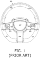
- FIG. 1 is a simplified illustration of a prior art steering wheel.
- a steering wheel 400 shown in FIG. 1 , includes a circular gripping member 401 , one or more connecting members 402 - 404 that connect the gripping member 401 to steering column 407 , and buttons 405 and 406 on connecting members 402 and 403 for controlling various devices in the vehicle.
- Connecting members 402 - 404 which connect gripping member 401 to steering column 407 , are also referred to as spokes.
- button 405 is used to answer an incoming phone call on the vehicle's BLUETOOTH ® speaker phone and button 406 hangs up the call.
- BLUETOOTH is a trademark owned by the Bluetooth SIG of Kirkland, WA, USA. Controls mounted in a steering wheel can be operated comfortably and safely since the driver is able to control and operate these controls without taking hands off the wheel or eyes off the road.
- Prior art cars are equipped with a safety device in the form of sensors in the steering wheel that detect whether the diver is gripping the wheel and issue a warning when the driver's hands are not on the wheel.
- the prior art sensors do not distinguish a human hand from any other object touching the wheel. This could lead certain drivers to trick the safety device by wrapping an object around the steering wheel grip when driving without holding on to the steering wheel.
- ADAS vehicles require driver intervention in certain situations. It would thus be advantageous to track and measure driver preparedness for such intervention in ADAS vehicles.
- the user interface for vehicle ignition is by pressing a button on the dashboard. It would be advantageous to provide user interfaces that are more user friendly and intuitive than a dashboard button.
- a vehicle including an advanced driver-assistance system (ADAS) that selectively performs and selectively stops performing automated vehicle navigation operations, a steering wheel with which a human driver steers the vehicle when the automated vehicle navigation operations are not performed, a sensor operable to detect a driver's hand at a plurality of locations on the steering wheel, a plurality of visible-light emitters operable to illuminate the plurality of locations on the steering wheel, and a processor, coupled with the ADAS, with the sensor and with the visible-light emitters, performing the following functions while the ADAS is performing the automated vehicle navigation operations: (i) an activating function that activates at least one of the emitters to illuminate a location on the steering wheel, (ii) a detecting function that detects, via the sensor, when the driver touches the illuminated location, and (iii) a calculating function that calculates a degree of driver preparedness for taking control of steering the vehicle when the ADAS stops performing the automated vehicle navigation operations, based on
- ADAS advanced driver-assistance system
- the processor detects, via the sensor, an initial location of the driver's hand on the steering wheel prior to performing the activating function, and selects a location on the steering wheel to illuminate based on the detected initial location.
- the processor detects, via the sensor, initial locations of the driver's two hands on the steering wheel prior to performing the activating function, and further identifies the driver's handedness based on which hand touches the illuminated location.
- the ADAS configures a parameter of the automated vehicle navigation operations in response to the degree of driver preparedness calculated by the processor.
- the parameter is, e.g., a distance from a vehicle ahead or vehicle speed.
- the ADAS navigates the vehicle to a parking location in response to a low degree of driver preparedness calculated by the processor.
- the processor configures the activating function based on a prior calculated degree of driver preparedness.
- the activating function selects an illumination color based on the prior calculated degree of driver preparedness.
- the ADAS instructs the processor to perform the activating, detecting and calculating functions, based on an anticipated change in driving conditions.
- the anticipated change in driving conditions is an automated navigation instruction to exit a highway.
- Light transmitters are numbered in the 100's
- light detectors are numbered in the 200's
- light guides and lenses are numbered in the 300's
- miscellaneous items are numbered in the 400's
- light beams are numbered in the 600's
- flow chart elements are numbered 1000 - 1100. Like numbered elements are similar but not necessarily identical.
- aspects of the present invention relate to light-based touch controls that allow a driver to keep his hands on a steering element while operating peripheral electronic devices and automated features in a vehicle.
- a steering wheel is provided with a touch sensitive strip disposed along the entire circumference of the steering wheel. In order to facilitate locating the strip, it is disposed in a thumb receiving notch or groove that is etched or otherwise formed along the circumference of the steering wheel.
- a touch sensor there is also a visible-light illuminator behind or around the touch sensitive strip that is used to indicate the state of the user interface to the user, and also indicate where certain tap gestures should be performed.
- a user interface for this steering wheel is designed to be independent of the rotation of the steering wheel. Sweep gestures are clockwise and counter-clockwise so that they are independent of rotation of the wheel.
- a function is activated in response to a gesture, such as a double-tap, performed anywhere along the circumference of the wheel.
- the activation of some functions places the user interface into a state in which one or more additional functions can be selectively activated.
- the touch location at which the initial gesture was performed is illuminated and subsequent gestures are performed in relation to the illuminated portion of the wheel.
- the illuminated portion of the steering wheel follows the hand so that the hand is always next to the location for performing subsequent gestures.
- the illumination jumps to the newly gripped part of the wheel.
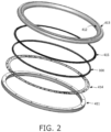
- FIG. 2 is an exploded view of a steering wheel, in accordance with an embodiment of the present invention.
- Elements of this steering wheel include steering wheel frame 411 , PCB 414 , an array of lenses 300 , a light baffle structure 415 , and a steering wheel top cover 412 .
- a thumb-receiving notch 413 is disposed within steering wheel cover 412 .
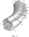
- FIG. 3 is a cutaway view of a segment of the steering wheel of FIG. 2 , in accordance with an embodiment of the present invention.
- Thumb-receiving notch 413 is illustrated in FIG. 3 .
- Two light transmissive portions of cover 412 are also shown in FIG. 3 .
- a first light transmissive portion 417 forms the side wall of thumb-receiving notch 413 . Light beams traveling into and out of this portion provide touch detection and proximity detection, as explained below.
- Three touch detection light beams 602 are shown directed radially outward from the steering wheel gripping element.
- the second light transmissive portion 416 forms a floor of thumb-receiving notch 413 , and is used for visible illumination indicating a state of the user interface to the driver, and at which location the driver should perform additional user interface gestures.
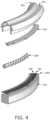
- FIGS. 4 and 5 are exploded views of the steering wheel segment illustrated in FIG. 3 , in accordance with an embodiment of the present invention.
- two concentric rows of elements are mounted on PCB 414 . Namely, an inner row of light detectors 200 and an outer row of light emitters 100 .
- Light from the emitters enters lenses 300 through which it is re-directed out of the steering wheel through light transmissive portion 417 as light beams 602 , illustrated in FIGS. 3 , 8 and 9 .
- An object such as a thumb placed in notch 413 reflects the light back through portion 417 and lenses 300 onto one or more of the light detectors 200 , thereby providing touch detection, as illustrated in FIG. 8 .
- an object such as a user's hand placed along the outer rim of the steering wheel outside notch 413 and opposite light transmissive portion 417 also reflects the light back through portion 417 and lenses 300 onto one or more of the light detectors 200 , thereby providing proximity detection.
- FIG. 5 shows an exploded view from below of the steering wheel segment illustrated in FIG. 3 , in accordance with an embodiment of the present invention.
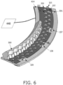
- FIG. 6 is a simplified illustration of electronic components in the steering wheel segment of FIG. 3 connected to a processor, in accordance with an embodiment of the present invention.
- FIG. 6 shows processor 440 connected to PCB 414 on which three concentric arrangements of light elements are mounted, namely, an inner circular arrangement of inward facing light detectors, including detectors 201 and 202 ; a middle circular arrangement of inward facing light emitters, including emitters 101 and 102 ; and an outer circular arrangement of outward facing light emitters 106 - 109.
- the inward facing light emitters are used for touch and proximity detection and typically emit light in the near infrared range.
- Processor 440 controls activation of the emitters and detectors, and detects gestures performed on the steering wheel based on these activations and based on the outputs of the detectors.
- the outward facing light emitters are used to provide visual indications to the user by illuminating light transmissive portion 416 of the steering wheel cover, and emit light in the visible range.
- Lenses 300 are described in U.S. Patent No. 9,741,184 , entitled DOOR HANDLE WITH OPTICAL PROXIMITY SENSORS, the contents of which are incorporated herein in their entirety by reference.
- FIG. 7 is a simplified illustration of a structure of light baffles placed upon the electronic components in FIG. 6 , in accordance with an embodiment of the present invention.
- FIG. 7 shows PCB 414 and lenses 300 of FIG. 6 , but with baffle structure 415 placed above the mounted light elements.
- FIG . 8 is a simplified illustration of light beams detecting an object, in accordance with an embodiment of the present invention.
- FIG . 8 illustrates a light path used to detect an object.
- Shown in FIG . 8 are individual lens structures 301 - 305.
- Each lens structure serves a respective opposite emitter and two detectors, one to the left of the emitter and one to the right of the emitter.
- lens structure 305 serves emitter 105 and detectors 205 and 206.
- each detector is served by two lens structures; e.g., detector 205 receives reflected light from lens structures 304 and 305.
- FIG. 8 is a simplified illustration of light beams detecting an object, in accordance with an embodiment of the present invention.
- FIG . 8 illustrates a light path used to detect an object.
- Shown in FIG . 8 are individual lens structures 301 - 305.
- Each lens structure serves a respective opposite emitter and two detectors, one to the left of the emitter and one to the right
- FIG. 8 light from emitter 105 is reflected by an object (not shown) into lens structure 303 and onto detector 203 .
- Three segments of the detected light are indicated in FIG. 8 ; namely, light beam 602 projected outward from lens structure 305 and radially outward of the steering wheel, light beam 603 reflected by the object into lens structure 303, and light beam 604 directed by lens structure 303 onto detector 203 .
- FIG. 9 is a simplified side view illustration of light beams projected radially outward from a steering wheel, in accordance with an embodiment of the present invention.
- FIG. 9 shows a cutaway side view of the light path illustrated in FIG. 8 .
- FIG. 9 shows light beam 601 from emitter 105 entering lens structure 305 , where it is redirected outward as light beam 602 .
- FIG. 10 is a simplified illustration of communication between touch detection firmware and multiple clients over a network, in accordance with an embodiment of the present invention.
- FIG. 10 shows an exemplary network architecture in which processor 440 sends detected gesture components over message bus 444 , e.g., using the Message Queue Telemetry Transport (MQTT) messaging protocol on top of the TCP/IP protocol, to connected clients 441 - 443.
- MQTT Message Queue Telemetry Transport
- the five basic gesture components are categorized according to whether they are performed by a large object (hand) or small object (thumb), and whether the nature of the gesture component is discrete or continuous, as presented in the table below.
- Component Description Object Type Thumb-Tap Tap thumb on steering wheel rim Small Discrete Thumb-Glide Glide thumb along steering wheel rim Small Continuous Thumb-Long-Press Hold thumb on steering wheel rim Small Continuous Grab Grab hold of steering wheel rim Large Continuous Rim-Tap Tap hand on steering wheel rim Large Discrete
- These gesture components are alternatively referred to as follows.
- Component Alternative Name Thumb-Tap small-object tap Thumb-Glide small-object glide Thumb-Long-Press small-object touch-and-hold Grab large-obiect grab Rim-Tap large-object tap
- the parameters are the same for all gesture components; namely, time stamp, start angle (min_angle), end angle (max_angle), center angle (angle) and state.
- the angle parameters refer to a polar angle along the steering wheel at which the object is detected. Because of the object's size, there is a first polar angle at which the object begins (start angle) and a last polar angle at which the object ends (end angle). The midpoint between the start and end angles (center angle) is used as the object's polar angle. The start and end angles are useful for determining the size of a detected object.
- the state parameter takes on three values: RECOGNIZED, UPDATED and ENDED.
- the ENDED state is applied to all discrete gesture components, and also when a continuous gesture component ends.
- the RECOGNIZED and UPDATED states are only applied to continuous gesture components.
- the RECOGNIZED state is applied when a continuous gesture component is first detected.
- the UPDATED state is applied during the course of a continuous gesture component.
- the discrete gesture components, Thumb-Tap and Rim-Tap, are emitted to the clients after they happen, and then only one message is sent for the gesture component. They are only sent with the state ENDED.
- the continuous gesture components Thumb-Glide, Thumb-Long-Press and Grab, are emitted to the clients intermittently from the instant that they are recognized until they end when the hand or finger leaves the rim.
- they are sent to the network with the state RECOGNIZED.
- the gesture component is reported to the network with new parameters and the state UPDATED.
- the gesture component ends, the gesture component is sent with the state ENDED.
- FIGS. 11A - 11E are simplified illustrations of five basic gesture components used in a steering wheel user interface.
- FIGS. 11A - 11E show the five gesture components performed by thumb 418 and hand 419 on steering wheel 410. Some gesture components are illustrated both from above and from the side. When illustrated from the side, thumb 418 is shown interacting with steering wheel surface 420.
- FIG. 11A shows that a Grab gesture component is the same as a Thumb-Glide gesture component, except for two distinctions: (i) the Grab gesture is performed by a large object touching the rim, and (ii) the Grab gesture component does not have to move to be reported on the network. When the hand has been on the rim for a certain time threshold, the Grab gesture component is recognized and messages are intermittently sent to the network.
- FIG. 11A shows the Grab gesture component from above by showing hand 419 gripping steering wheel 410.
- FIG. 11B shows that a Thumb-Tap gesture component is generated when a small object touches, or gets very close to, the rim and is then lifted from the rim within a short period of time. This period is configurable, but typically it is 100-200 ms.
- FIG. 11B shows the Thumb-Tap gesture component from above and from the side, and illustrates the movement of thumb 418 by arrows 421.
- FIG. 11C shows that a Thumb-Long-Press gesture component is generated when a small object is present, and not moving, on the rim.
- messages are sent intermittently to the network about the gesture component. If the object starts moving, the Thumb-Long-Press gesture component is ended and a Thumb-Glide gesture component is started instead.
- FIG. 11C shows the Thumb-Long-Press gesture component from above and from the side.
- Clock icon 425 indicates the time threshold required to distinguish this gesture component from a Thumb-Tap.
- FIG. 11D shows that a Thumb-Glide gesture component is generated when a small object touches the rim and moves at least a certain threshold distance along the rim. That distance is configurable. When it continues to move, UPDATE messages are sent when the object has moved a certain distance, also configurable.
- FIG. 11D shows the Thumb-Glide gesture component from above and from the side, and illustrates the movement of thumb 418 by arrows 422 and 423.
- FIG. 11E shows that a Rim-Tap gesture component is the same as a Thumb-Tap, but for a large object such as a hand.
- FIG. 11E shows the Rim-Tap gesture component from the side and illustrates the movement of hand 419 by arrows 424.
- gesture components are combined into compound user interface gestures.
- environment conditions at the gesture location are combined with the gesture component to define a gesture. For example, a Thumb-Tap gesture performed at one end of an illuminated portion of the rim is translated into a first command, and a Thumb-Tap gesture performed at the other end of the illuminated portion of the rim is translated into a second command.
- the following table lists the different gestures and compound gestures in an exemplary steering wheel user interface, the gesture components that make up each gesture, additional gesture parameters, and example context and commands for each gesture.
- FIG. 12 is a flowchart of an exemplary vehicle user interface.
- the flowchart illustrates the different application states, different commands within each state, and the gestures used to issue those commands. The details of the gestures are illustrated in FIGS. 13 - 19 .
- a head-up display (HUD) is provided.
- the flowchart of FIG. 12 illustrates a highway scenario that includes three driving modes: Normal Drive 1001 , Adaptive Cruise Control 1002 and Autonomous Drive 1003.
- Normal Drive mode the driver steers the vehicle and controls its speed.
- Adaptive Cruise Control mode the driver steers the vehicle but the vehicle's speed, its distance from the next vehicle on the road, and other parameters are controlled by the vehicle.
- Autonomous Drive mode the vehicle is driven and steered automatically without driver input.
- the user enters Adaptive Cruise Control mode from Normal Drive mode by performing a double-tap gesture.
- the user enters Autonomous Drive mode from Normal Drive mode and from Adaptive Cruise Control mode by performing a multi-touch double-tap gesture. These gestures are described below.
- the steering wheel is illuminated with an illumination pattern that indicates a countdown until Autonomous Drive is activated.
- the user exits Adaptive Cruise Control mode by performing a double-tap gesture that opens a menu on the HUD for changing the mode 1015 of cruise control.
- the user performs clockwise or counter-clockwise swipe gestures to scroll through the different modes on the HUD, and performs a single-tap gesture to select the displayed mode.
- One of the modes is Exit ACC 1018 , and selecting this mode exits Adaptive Cruise Control.
- Another mode configures the cruise control application to follow the road signage 1019 .
- Autonomous Drive mode 1013 by grabbing the rim of the steering wheel.
- the steering wheel is illuminated with an illumination pattern that indicates a countdown until Autonomous Drive is deactivated.
- the vehicle Upon exiting Autonomous Drive mode, the vehicle enters Adaptive Cruise Control mode.
- Adaptive Cruise Control mode 1002 the user adjusts a distance 1016 between the vehicle and the vehicle directly in front of it, by performing a clockwise or counter-clockwise swipe gesture.
- the user adjusts the speed of the vehicle 1017 by performing either a tap gesture or an extended touch gesture.
- a segment of the steering wheel is illuminated.
- a tap gesture or extended touch gesture at one end of the illuminated segment increases the vehicle speed, and a tap gesture or extended touch gesture at the other end of illuminated segment decreases the vehicle speed.
- a voice control state 1004 can be entered from Normal Drive mode and Adaptive Cruise Control mode.
- the user can initiate a phone call by saying " call " and the name of a contact from his phone's contact list. Once the call has been connected, the user can hang up 1010 by performing a clockwise swipe gesture. The user can also adjust the volume 1011 by saying the word " volume " and then performing a counter-clockwise swipe gesture to raise the volume, or a clockwise swipe gesture to lower the volume.
- the user can answer the call 1012 by performing a counter-clockwise swipe gesture, or decline the call 1012 by performing a clockwise swipe gesture.
- FIGS. 13A - 13I are simplified illustrations of user interface gestures performed on a steering wheel for an adaptive cruise control function.
- Adaptive Cruise Control mode from Normal Drive mode the user performs a single-object double-tap gesture. Namely, the user taps twice with his thumb on the thumb notch in the steering wheel. This gesture is shown in FIG. 13A , showing steering wheel 410, hand 419 gripping steering wheel 410, and double-tap gesture 430.
- the present example enables the user to perform the double-tap gesture 430 at any location along the perimeter of steering wheel 410.
- Adaptive Cruise Control When Adaptive Cruise Control is active the user has four options; namely, adjust cruise control speed, adjust the distance between the vehicle and the vehicle ahead, open an adaptive cruise control menu, and activate Autonomous Drive mode.
- Adaptive Cruise Control is activated when the user taps twice with his thumb in the steering wheel thumb notch. The location of these taps is subsequently illuminated to indicate to the user where to perform future gestures. This is illustrated in FIG. 13B , which shows illuminated segment 436 of the steering wheel 410 at the location at which double-tap 430 was performed.
- a gesture e.g., a single-tap, above the illuminated portion. This is illustrated in FIG.
- FIG. 13D which shows tap gesture 438 at the counter-clockwise edge of illuminated portion 436 .
- the “+” indicates that this gesture increases the speed of the vehicle.
- FIG. 13E shows gesture 438 performed at the clockwise end of illuminated portion 436 , and the "-" indicates that the gesture decreases the speed of the vehicle.
- the illuminated portion 436 moves with the hand so that the user's thumb is always next to the illuminated portion of the steering wheel. This is shown in FIG. 13C , in which hand 419 gripping steering wheel 410 slides clockwise as indicated by arrow 428 , and illuminated portion 436 also slides in the same direction as indicated by arrow 437.
- the cruise control speed is also adjusted in response to extended touch gestures above and below the illuminated portion of the steering wheel.
- the speed is adjusted by 5 km/h in response to a tap gesture, and is adjusted by 1 km/h in response to an extended touch gesture.
- FIGS. 13F and 13G show a counter-clockwise gesture 431 to increase the distance between vehicles
- FIG. 13G shows a clockwise gesture 432 to decrease the distance between vehicles.
- FIGS. 13H and 13I show swipe gesture 433 that moves outward across the width of illuminated portion 436 .
- FIG. 13I shows swipe gesture 434 that moves inward across the width of illuminated portion 436 .
- Either gesture causes the HUD to present a mode option for selection.
- the user performs a single-tap gesture with his thumb in the steering wheel notch to accept the displayed mode.
- the mode displayed in the HUD is changed in response to a swipe gesture. For example, a first mode is to follow road signage.
- the follow Road Signage mode is activated. If the user swipes clockwise or counter-clockwise, a next or previous mode is displayed such as exit Adaptive Cruise Control. The user performs a single-tap to activate this mode. If no interaction from the user is received within a fixed amount of time, such as 5 seconds, then the change mode user interface is deactivated.
- FIG. 14 is a simplified illustration of a multi-touch double-tap gesture to activate an autonomous drive mode.
- FIG. 14 illustrates two fingers, 418 and 426 , simultaneously tapping at two locations on steering wheel 410.
- the upper part of this drawing is a view from above, and the lower part of this drawing is a view from the side of each of the fingers 418 and 426.
- the tap gesture is a brief down and up gesture illustrated by arrows 421 and 428 touching surface 420 of the steering wheel.
- FIGS. 15A and 15B are simplified illustrations of a user interface indicating activation of an autonomous drive mode.
- a series of locations on the steering wheel is sequentially illuminated over time to indicate a countdown until Autonomous Drive is activated, as shown in FIGS. 15A and 15B .
- FIG. 15A shows a sequence of illuminations that begins with (i) the 2:30 and 9:30 clock positions indicated by a 1; followed by (ii) the 1:30 and 10:30 clock positions indicated by 2; followed by (iii) the 12:30 and 11:30 clock positions indicated by 3.
- FIG. 15B shows finally illuminating the 12 o'clock position to inform the user that Autonomous Drive is activated and the user can safely take his hands off the wheel.
- FIGS. 16A and 16B are simplified illustrations of a gesture and an exemplary user interface for exiting autonomous drive mode.
- FIG. 16A shows two hands 419 gripping steering wheel 410. A series of locations on the steering wheel is then sequentially illuminated to indicate that Autonomous Drive mode is about to be the deactivated.
- FIG. 16A shows a sequence of illuminations that begins with (i) the 11:30 and 12:30 clock positions indicated by a 1; followed by (ii) the 10:30 and 1:30 clock positions indicated by 2; followed by (iii) the 9:30 and 2:30 clock positions indicated by 3.
- FIG. 12 Two voice-activated controls are illustrated in FIG. 12 : placing a phone call and enabling volume adjustments.
- To place a phone call the user says " call " and the name of the person to call, e.g., " call Mom ".
- the user In order to hang up the call the user performs a swipe gesture along the thumb notch in the steering wheel.
- To adjust the volume of a call or the stereo system the user says the word “ volume " and then adjusts the volume up or down by swiping clockwise or counter-clockwise along the thumb notch in the steering wheel.
- FIGS. 17A and 17B are simplified illustrations showing how an incoming call is received.
- FIG. 17A shows two hands 419 gripping wheel 410
- FIG. 17B shows that when an incoming call is received, the user answers or declines the call by swiping finger 418 of one hand gripping the wheel, clockwise or counter-clockwise along the thumb notch of the steering wheel, e.g., swipe counter-clockwise to accept the call and swipe clockwise to reject the call.
- FIGS. 18A and 18B are simplified illustrations showing how to hang up a call.
- the gesture to hang up a call is a clockwise swipe gesture.
- the system ignores clockwise swipe gestures so that the user does not inadvertently hang up the call.
- the user In order to hang up the call, the user first taps the outer rim of the steering wheel, as shown by hand 419 in FIG. 18A , to indicate that the system should respond to the next swipe gesture, followed by a clockwise swipe gesture by finger 418 to hang up the call, as shown in FIG. 18B .
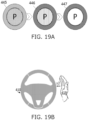
- FIGS. 19A and 19B are simplified illustrations of a user interface for a park assist function.
- the Park Assist function begins automatically scanning for available parking spaces.
- a faded Park Assist icon 445 appears on the HUD, as illustrated in FIG. 19A .
- this icon becomes bolder 446 , 447 until the car has stopped moving.
- the HUD presents information about available parking spots, e.g., whether the vehicle can fit into an available spot.
- the user performs a double-tap on the outer rim of the steering wheel, as illustrated in FIG.
- Embodiments known from US Publication No. 2015/123947 A1 do not form part of the invention.
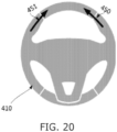
- FIGS. 20 - 26 are simplified illustrations of multi-finger pinch and stretch gestures.
- FIG. 20 shows a compound multi-finger gesture along a steering wheel rim.
- two objects simultaneously move toward each other along opposing portions of steering wheel rim 410, as indicated by movement arrows 450 and 451.
- this multi-finger gesture is interpreted as a two-finger pinch gesture on a touch screen.
- a displayed image is zoomed out.
- FIG. 21 shows a second compound multi-finger gesture along a steering wheel rim.
- two objects simultaneously move away from each other along opposing portions of steering wheel rim 410, as indicated by arrows 452 and 453.
- this multi-finger gesture is interpreted as a two-finger stretch gesture on a touch screen.
- a displayed image is zoomed in.
- both objects touching the wheel need not move; the gesture is defined by the relative movement between the two objects. If one object remains in place while the other object moves, the relative movement of the two objects defines the gesture.
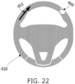
- FIG. 22 shows a compound multi-finger gesture performed on steering wheel 410 in which element 466 is a finger that remains at one place throughout the gesture, while a second finger moves clockwise along the steering wheel rim, as indicated by arrow 451 , progressively decreasing the distance between the two fingers. This gesture is interpreted as a pinch gesture.
- FIG. 23 shows a compound multi-finger gesture performed on steering wheel 410 in which element 466 is a finger that remains at one place throughout the gesture, while a second finger moves counterclockwise along the steering wheel rim, as indicated by arrow 453 , progressively increasing the distance between the two fingers.
- This gesture is interpreted as a stretch gesture.
- FIG. 24 shows a compound multi-finger gesture performed on touch pads provided on spokes of a steering wheel.
- two objects simultaneously move toward each other along touch pads 460 and 461 situated on opposite sides of central hub 407 , as indicated by arrows 454 and 455.
- this multi-finger gesture is interpreted as a two-finger pinch gesture on a touch screen.
- a displayed image is zoomed out.
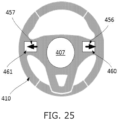
- FIG. 25 shows a compound multi-finger gesture performed on touch pads provided on spokes of a steering wheel.
- two objects simultaneously move away from each other along touch pads 460 and 461 situated on opposite sides of central hub 407 , as indicated by arrows 456 and 457.
- this multi-finger gesture is interpreted as a two-finger stretch gesture on a touch screen.
- a displayed image is zoomed in.
- a user performs gestures on two separate areas on or around the steering wheel, and those gestures are interpreted as a single, multi-finger gesture.
- the multi-finger gesture is defined by the movement of the fingers in relation to each other, as in pinch gestures and rotation gestures.
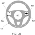
- FIG. 26 shows a compound multi-finger gesture performed on touch pads 460 and 461 on steering wheel 410.
- Element 467 indicates a finger that remains at one place on touch pad 461 throughout the gesture, while a second finger moves 454 across touch pad 460 toward center 407 of the wheel, progressively decreasing the distance between the two fingers. This gesture is interpreted as a pinch gesture.
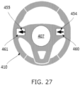
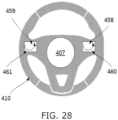
- FIGS. 27 and 28 are simplified illustrations of multi-finger gestures.
- FIG. 27 shows a compound multi-finger gesture performed on touch pads 460 and 461 on steering wheel 410. In this case both fingers move in the same direction on their respective touch pads, as indicated by arrows 454 and 455. This gesture is interpreted as a panning gesture, in response to which the user interface pans an image.
- FIG. 28 shows a compound multi-finger gesture performed on touch pads 460 and 461 on steering wheel 410.
- both fingers move in tandem tracing a curve on their respective touch pads, as indicated by arrows 458 and 459.
- This gesture is interpreted as a panning gesture, in response to which the user interface pans an image. The pan follows the direction of the finger movement, and is therefore not in a straight line.
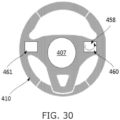
- FIGS. 29 and 30 are simplified illustrations of one-finger gestures.
- FIGS. 29 and 30 show one-finger gestures performed on touch pad 460 on steering wheel 410 , as indicated by respective arrows 454 and 458. Because only one finger is used, these gestures are interpreted differently than the multi-finger gestures discussed hereinabove. In some cases these one-finger gestures are interpreted as panning gestures, whereby the user interface pans the image at a different speed than when two-finger panning gestures are performed. In other cases the user interface behavior in response to these gestures is the same as to the gestures shown in FIGS. 27 and 28 in which two fingers move across different surfaces in the same direction.
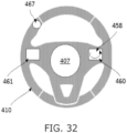
- FIGS. 31 - 34 are simplified illustrations of multi-finger gestures.
- FIGS. 31 and 32 show compound gestures performed on touch pad 460 and on the rim of steering wheel 410.
- a finger is stationary on the steering wheel rim, as indicated by element 467 , while another finger performs a moving gesture on touch pad 460 , as indicated by arrows 454 and 458.
- the compound gesture elicits a different response from the user interface than each of the individual gestures that make up the compound gesture.
- at least one of the compound gesture's parameters is how the two or more objects performing the gesture relate to each other. For example, whether the distance between the objects is increasing, decreasing, or remains the same, i.e., the objects move in tandem with each other.
- a compound gesture represents a combination of two or more known multi-touch gestures and the steering wheel user interface reacts by executing the multiple corresponding commands simultaneously.
- FIG. 33 shows a compound gesture performed on touch pad 461 and on the rim of steering wheel 410.
- a finger is stationary on touch pad 461 , as indicated by element 467 , while another finger performs moving gesture 452 on the steering wheel rim.
- the finger performing a gesture on the rim can be replaced by a hand.
- only finger gestures on the steering wheel rim are combined with another gesture into a compound gesture, whereas a gesture performed by a hand is not combined with another gesture into a compound gesture.
- Fingers and hands are distinguished from each other by their sizes as determined by the number of emitter-detector pairs that detect them.
- FIG. 34 shows a compound gesture performed on touch pad 460 and on the rim of steering wheel 410.
- a finger is performing curved sweep gesture 458 on touch pad 460 while another finger performs counterclockwise sweep gesture 453 on the steering wheel rim.
- Examples disclosed herein verify that the driver is gripping a steering wheel. Simply detecting that an object is gripping the steering wheel is not sufficient to determine that a driver is gripping the wheel. For example, such detection cannot distinguish a hand from an inanimate object wrapped around a portion of the steering wheel. Examples use the light-based proximity sensors in the steering wheel to distinguish between a human hand gripping the wheel and an inanimate object gripping the wheel by detecting two distinguishing features of a human hand: micro-movements and blood flow.
- FIG. 35 is a simplified illustration of micro-movements detected on a steering wheel.
- Micro-movements are very small movements of the hand gripping the wheel.
- FIG. 35 shows hand 419 gripping wheel 410.
- Arrow 465 illustrates the direction of micro-movements detected by the steering wheel sensor described hereinabove in relation to FIGS. 2 - 7 .
- These movements are miniscule, not as large as arrow 465 , but they cause the steering wheel sensor detections at the edges of the hand to fluctuate in response to these movements.
- these detected large movements also serve to indicate that the driver is in control of the wheel.
- micro-movement detection is only required in the absence of large movements.
- FIG. 36 is a simplified illustration of blood flow through a hand, the blood flow being detected by a reflectance-based sensor.
- Blood flowing through hand 419 gripping wheel 410 in FIG. 35 causes fluctuations in the steering wheel sensor detections when the skin of hand 419 is exposed to the thumb-receiving notch in steering wheel 410 , based on a technique used for non-invasively monitoring oxygen saturation and pulse rate known as "reflectance-based pulse oximetry".
- reflectance-based pulse oximetry incident light is passed through the skin and is reflected off the subcutaneous tissue and bone.
- the infrared or near infrared light beams from the proximity sensor emitters pass through the skin of the driver's hand gripping the wheel and are reflected off the subcutaneous tissue and bone back to the proximity sensor light detectors.
- a red light is used instead of infrared or near infrared light.
- the reflectance-based pulse oximetry signals may be unstable due to user movement. In some cases, this is compensated for by signal processing by the proximity sensor controller, or by post-processing by the host processor, based on tracking the movement.
- blood flow is identified only when the hand gripping the wheel is not moving. When the hand gripping the wheel is moving, the tracked movement of the hand indicates that it is a human hand gripping the wheel, and blood flow is not identified.
- FIGS. 37 - 44 are graphs of filtered detections of blood flow inside a hand gripping a steering wheel equipped with reflectance-based sensors.
- FIG. 37 is a graph of filtered detections of a hand by the steering-wheel mounted optical proximity sensor described hereinabove using a transmit current of 150 mA to activate the emitters. The detection signal was filtered with the Fourier transform and the graph shows the expected modulation in the reflected light. In some examples, an automatic gain control loop is used for the pulse sensing channel, as saturating the receiver would block the modulation.
- a pitch detection algorithm is used to estimate the pitch, or fundamental frequency of the detection signal.
- the "harmonic product spectrum” is a pitch detection algorithm used in certain examples to identify the fundamental frequency in the detections.
- FIG. 38 is a graph of filtered detections of a hand by the steering-wheel mounted optical proximity sensor described hereinabove.
- the detection signal was filtered in the time domain using a 16-point averaging filter.
- the graph in FIG. 38 was generated by sampling only one channel detecting the hand, at a 1 kHz sample rate. In other examples, averaging is additionally or alternatively performed on neighboring channels within a scan sequence.
- FIG. 39 is a graph of filtered detections of a hand by the steering-wheel mounted optical proximity sensor described hereinabove.
- the detection signal was filtered twice using a 16-point averaging filter, i.e., the output of a 16-point averaging filter is filtered again with a 16-point averaging filter.
- the signal in FIG. 39 is cleaner than that of FIG. 38 .
- FIG. 40 is a graph of detections of a hand by the steering-wheel mounted optical proximity sensor described hereinabove, using infrared light emitters at a rate of 74Hz, and an over-sampling ratio of 16.
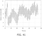
- FIG. 41 is a graph of detections of a hand by the steering-wheel mounted optical proximity sensor described hereinabove, using infrared light emitters at a rate of 74 Hz, an over-sampling ratio of 16, and a 16-tap finite impulse response (FIR) filter.
- infrared light emitters at a rate of 74 Hz
- over-sampling ratio of 16
- FIR finite impulse response
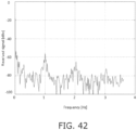
- FIG. 42 is a graph of detections of a hand by the steering-wheel mounted optical proximity sensor described hereinabove, using red light emitters at a rate of 74 Hz and an over-sampling ratio of 16.
- FIG. 43 is a graph of detections of a hand by the steering-wheel mounted optical proximity sensor described hereinabove, using red light emitters at a rate of 74 Hz, an over-sampling ratio of 16, and a 16-tap FIR filter.
- FIGS. 40 - 43 show that although the visible red light provides a stronger overall signal, it provides a weaker modulation than IR light. Therefore, IR light is better than visible light for detecting blood flow.
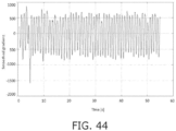
- FIG. 44 is a graph of detections of a hand by the steering-wheel mounted optical proximity sensor described hereinabove, in which the time domain signal was high-pass filtered to reject low frequency variation and then filtered again with a 32-tap FIR to smooth the waveform.
- FIG. 45 is a pair of graphs, namely, a top graph of detections of blood flow inside a hand gripping a steering wheel, and a bottom graph of an estimated period in the detections of the top graph.
- FIG. 45 shows how to estimate a period in the signal of FIG. 41 , reproduced at the top of FIG. 45 , by calculating the number of samples between falling zero crossings. The estimated period is shown in the graph at the bottom of FIG. 45 .
- the low pass variation in the signal of FIG. 41 is attenuated, but sharp changes affect the result.
- the remaining ripple on the estimated pulse frequency in the graph at the bottom of FIG. 45 is too high.
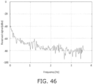
- FIG. 46 is a graph illustrating the spectrum of a pulse-detection signal.
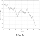
- FIG. 47 is a graph illustrating modulation of a pulse-detection signal over time.
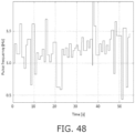
- FIG. 48 is a graph illustrating an estimated frequency of a pulse-detection signal. In examples, this pulse detection signal is used to calculate a pulse rate of the driver.
- SAE J3016 levels and definitions include:
- the Automated Driving System operates in accordance with the assumption that the human driver will respond appropriately to a request to intervene.
- the present invention provides systems that measure a degree of driver preparedness to intervene.
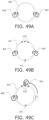
- FIGS. 49A - 49C are simplified illustrations of a system for measuring driver alertness, in accordance with an embodiment of the present invention.
- FIG. 49A shows steering wheel 410 provided with sensors that detect the position of hands 468 and 469 gripping the wheel.
- FIG. 49B shows that steering wheel 410 also includes illuminators, such as illuminators 470 and 471 along the perimeter of steering wheel 410 . Based on the current location of the driver's hands on steering wheel 410 , the system illuminates one or more locations separate from the driver's hands and prompts the driver to touch the illuminated portions.
- the prompt is, for example, an audio or visual prompt.
- FIG. 49A shows steering wheel 410 provided with sensors that detect the position of hands 468 and 469 gripping the wheel.
- FIG. 49B shows that steering wheel 410 also includes illuminators, such as illuminators 470 and 471 along the perimeter of steering wheel 410 .
- the system Based on the current location of the driver's hands on steering wheel 410
- a degree of driver preparedness is derived based on the amount of time it takes the driver to touch the illuminated portions of steering wheel 410.
- the degree of driver preparedness is also derived based on how close the driver's touch is to the illumination.
- the illumination is generated at a midpoint between the driver's hands on steering wheel 410 , and the system determines the driver's handedness based on which hand was used to touch the illumination.
- the system prompts the driver to grip steering wheel 410 prior to illuminating portions of steering wheel 410 .
- a system for measuring a degree of driver preparedness uses a touch screen in the dashboard or elsewhere in the vehicle, instead of steering wheel 410 , to measure reaction time.
- a location on the touch screen is indicated for the driver to touch and the time it takes the driver to touch the screen location indicates the degree of driver preparedness.
- the system for measuring a degree of driver preparedness is activated when the Automated Driving System predicts a likelihood that driver intervention will be required soon. This typically occurs when driving conditions change; e.g., the car navigation system instructs the car to exit the highway, it has begun to rain, or the sun is setting and it is getting dark.
- the Automated Driving System requires a minimum degree of driver preparedness to proceed. If driver preparedness is below this threshold, the Automated Driving System reacts defensively, e.g., by increasing the distance to other vehicles on the road, by reducing vehicle speed, or by navigating the vehicle to a location where it parks the car. The Automated Driving System then resumes its previous course when driver preparedness increases. Similarly, the Automated Driving System uses the degree of driver preparedness to adapt driving parameters to the driver's abilities. E.g., the Automated Driving System drives defensively for a driver whose preparedness scores are consistently low, e.g., by increasing the distance to other vehicles on the road and reducing vehicle speed. Sometimes, a low reaction time is due to the driver not noticing the illumination. Therefore, in some cases, the illumination color or intensity is modified to catch the driver's attention. Blinking the illumination is also useful for catching the driver's attention.
- FIG. 50 is a simplified illustration of a gesture for starting a vehicle.
- FIG. 50 shows a gesture for starting a vehicle engine for vehicles that include an array of sensors along the perimeter of the steering wheel grip.
- the gesture of FIG. 50 involves the user's hands 468 , 469 sliding 472 , 473 along the grip around the steering wheel 410 .
- the gesture is performed symmetrically by both hands simultaneously, each hand performing an extended slide gesture along a different half of the steering wheel grip. For example, the left hand slides downward along the left half of the grip, while the right hand slides downward along the right half of the grip. In other cases, this gesture is used for activating functions other than starting the engine.
- the gesture of FIG. 50 has several benefits. By performing the gesture across the entire steering wheel grip, all sensors in the grip are tested, ensuring that all sensors are working properly each time the car is started. The vehicle generates an error state when not all locations along the length of the grip detect touch.
- the sensor is reflection-based, when the driver wears gloves the sensor detects different amounts of light than when the driver is not wearing gloves. Also, even without gloves, different skin tones reflect different amounts of light. Requiring the driver to perform this extended slide gesture when starting the vehicle, provides an opportunity to calibrate the sensors for the current driver's hands when this extended gesture is performed. In addition, the extended slide gesture wipes away dirt and dust from the grip that would interfere with the steering wheel touch sensor.
- FIGS. 51A , 51B , 52 and 53 are simplified illustrations of systems with duplicated touch sensors.
- FIGS. 51A and 51B show a first embodiment of a duplicated sensor system for touch pad controls.
- FIG. 51A shows touch pads 460 and 461 in steering wheel 410 . Use of these pads is discussed hereinabove with reference to FIGS. 24 - 34 .
- FIG. 51B shows two sensors 474 and 475 placed along different edges of pad 460 , each sensor 474 and 475 providing independent touch and gesture detection on pad 460 .
- Resistive and capacitive sensors require a film or layer on the touch surface, which precludes providing two independent resistive or capacitive sensors on the same area or on a steering wheel grip.
- reflection-based sensors are useful for providing multiple independent sensors for the same area.
- a touch pad or steering wheel is covered with a capacitive sensor, and in addition, a reflectance based sensor provides a second sensor thereon.
- two or more reflectance-based sensors provide duplicate sensing to the same area by placing different sensors along different edges of the area, enabling up to four independent reflectance-based sensors detecting touch and gestures on any rectangular area.
- the different reflectance-based sensors are stacked one above the other on a common edge of the detection area.
- the different sensors detect objects in adjacent detection planes, but all sensors will detect gestures and touches on the touch pad.
- FIG. 52 shows a second duplicated sensor system.
- the emitters and detectors of two reflectance-based sensors are interleaved.
- FIG. 52 illustrates this duplicated sensor system in a section of a steering wheel grip.
- FIG. 52 shows emitter beams 605 from a first of the two sensors, and emitter beam 606 from the second of the two sensors.
- both sensors detect objects in the same plane.
- Each sensor is controlled by a respective one of CPUs 476, 477.
- Steering wheel frame 411, top cover 412, thumb-notch 413 , PCB 414 , and transparent cover sections 416 and 417 are described hereinabove with reference to FIGS. 2 - 9 .
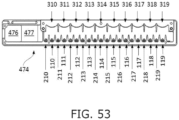
- FIG. 53 shows interleaved emitters and detectors of two sensors in a duplicated sensor system.
- FIG. 53 illustrates a duplicated sensor system in a one-dimensional sensor array 474.
- Each sensor is controlled by a respective one of processors 476 , 477. Every other emitter, together with its right-neighbor detector belongs to a first of the sensors and the remaining emitters and detectors belong to the other sensor; i.e., even-numbered emitters and detectors 110 , 210 , 112 , 212 , ..., 118 , 218 , are controlled by CPU 476 and odd-numbered emitters and detectors 111 , 211 , 113 , 213 , ..., 119 , 219 , are controlled by CPU 477.
- Lenses 310 - 319 direct light from the emitters out of sensor array 474 and direct object reflections onto the detectors, as explained hereinabove with reference to FIG. 8 .
- In other arrangements place two detectors between every two emitters, whereby every other emitter, together with one of its right-neighbor detectors and one of its left-neighbor detectors, belongs to a first of the sensors and the remaining emitters and detectors belong to the other sensor.
Landscapes
- Engineering & Computer Science (AREA)
- Health & Medical Sciences (AREA)
- Transportation (AREA)
- Mechanical Engineering (AREA)
- Combustion & Propulsion (AREA)
- Chemical & Material Sciences (AREA)
- Life Sciences & Earth Sciences (AREA)
- Physics & Mathematics (AREA)
- Automation & Control Theory (AREA)
- Veterinary Medicine (AREA)
- Animal Behavior & Ethology (AREA)
- Human Computer Interaction (AREA)
- Public Health (AREA)
- General Health & Medical Sciences (AREA)
- Surgery (AREA)
- Molecular Biology (AREA)
- Medical Informatics (AREA)
- Biophysics (AREA)
- Pathology (AREA)
- Biomedical Technology (AREA)
- Heart & Thoracic Surgery (AREA)
- General Engineering & Computer Science (AREA)
- Physiology (AREA)
- Cardiology (AREA)
- Hematology (AREA)
- Theoretical Computer Science (AREA)
- Psychology (AREA)
- Hospice & Palliative Care (AREA)
- Psychiatry (AREA)
- General Physics & Mathematics (AREA)
- Child & Adolescent Psychology (AREA)
- Educational Technology (AREA)
- Social Psychology (AREA)
- Developmental Disabilities (AREA)
- Mathematical Physics (AREA)
- Position Input By Displaying (AREA)
- Steering Controls (AREA)
- Measuring Pulse, Heart Rate, Blood Pressure Or Blood Flow (AREA)
Claims (12)
- Fahrzeug, umfassend:ein fortschrittliches Fahrerassistenzsystem (ADAS), das die automatische Fahrzeugnavigation selektiv durchführt und selektiv beendet;ein Lenkrad (410), mit dem ein menschlicher Fahrer das Fahrzeug lenkt, wenn die automatischen Fahrzeugnavigationsvorgänge nicht durchgeführt werden;einen Sensor (414, 100, 200, 300, 440), der die Hand des Fahrers an mehreren Stellen des Lenkrads erkennen kann;eine Vielzahl von Sendern für sichtbares Licht (106 - 109), die so betrieben werden können, dass sie die Vielzahl von Stellen auf dem Lenkrad beleuchten; undeinen Prozessor (441 - 443), der mit dem ADAS, mit dem Sensor und mit den Sendern für sichtbares Licht gekoppelt ist und die folgenden Funktionen ausführt, während das ADAS die automatischen Fahrzeugnavigationsvorgänge durchführt:(i) eine Aktivierungsfunktion, die mindestens einen der Sender aktiviert, um eine Stelle des Lenkrads zu beleuchten,(ii) eine Erkennungsfunktion, die über den Sensor erkennt, wenn der Fahrer die beleuchtete Stelle berührt, und(iii) eine Berechnungsfunktion, die einen Grad der Bereitschaft des Fahrers berechnet, die Kontrolle über die Lenkung des Fahrzeugs zu übernehmen, wenn das ADAS aufhört, die automatisierten Fahrzeugnavigationsvorgänge durchzuführen, basierend auf mindestens einer der folgenden Größen: Zeit, die zwischen der Aktivierungsfunktion und der Erkennungsfunktion verstrichen ist, und Nähe der Berührung des Fahrers zu dem beleuchteten Ort.
- Fahrzeug nach Anspruch 1, das ferner ein Audiosystem umfasst, wobei die Aktivierungsfunktion das Audiosystem veranlasst, dem Fahrer eine akustische Aufforderung zu geben, die beleuchtete Stelle zu berühren.
- Fahrzeug nach Anspruch 1, wobei der Prozessor (441 - 443) über den Sensor eine anfängliche Position der Hand des Fahrers auf dem Lenkrad erkennt, bevor die Aktivierungsfunktion ausgeführt wird, und eine zu beleuchtende Stelle auf dem Lenkrad basierend auf der erkannten anfänglichen Position auswählt.
- Fahrzeug nach Anspruch 1, wobei der Prozessor (441 - 443) über den Sensor die anfänglichen Positionen der beiden Hände des Fahrers auf dem Lenkrad erkennt, bevor die Aktivierungsfunktion ausgeführt wird, und ferner die Händigkeit des Fahrers basierend darauf identifiziert, welche Hand die beleuchtete Position berührt.
- Fahrzeug nach Anspruch 1, wobei das ADAS einen Parameter der automatisierten Fahrzeugnavigationsvorgänge in Reaktion auf den vom Prozessor berechneten Grad der Bereitschaft des Fahrers konfiguriert.
- Fahrzeug nach Anspruch 5, wobei der Parameter ein Abstand zu einem vorausfahrenden Fahrzeug ist.
- Fahrzeug nach Anspruch 5, wobei der Parameter eine Fahrzeuggeschwindigkeit ist.
- Fahrzeug nach Anspruch 1, wobei das ADAS das Fahrzeug als Reaktion auf einen vom Prozessor berechneten niedrigen Grad der Bereitschaft des Fahrers zu einer Parkposition navigiert.
- Fahrzeug nach Anspruch 1, wobei der Prozessor (441 - 443) die Aktivierungsfunktion auf der Grundlage eines zuvor berechneten Grades der Bereitschaft des Fahrers konfiguriert.
- Fahrzeug nach Anspruch 9, wobei die Aktivierungsfunktion eine Beleuchtungsfarbe auf der Grundlage des zuvor berechneten Grades der Bereitschaft des Fahrers auswählt.
- Fahrzeug nach Anspruch 1, wobei das ADAS den Prozessor (441 - 443) anweist, die Aktivierungs-, Erkennungs- und Berechnungsfunktionen auf der Grundlage einer voraussichtlichen Änderung der Fahrbedingungen durchzuführen.
- Fahrzeug nach Anspruch 11, wobei die voraussichtliche Änderung der Fahrbedingungen eine automatische Navigationsanweisung zum Verlassen einer Autobahn ist.
Priority Applications (1)
| Application Number | Priority Date | Filing Date | Title |
|---|---|---|---|
| EP24164453.3A EP4417481A3 (de) | 2017-03-20 | 2018-03-06 | Berührungssensorsysteme und verfahren für fahrzeuge |
Applications Claiming Priority (3)
| Application Number | Priority Date | Filing Date | Title |
|---|---|---|---|
| US201762473524P | 2017-03-20 | 2017-03-20 | |
| US201762567765P | 2017-10-04 | 2017-10-04 | |
| PCT/US2018/020989 WO2018175101A1 (en) | 2017-03-20 | 2018-03-06 | Touch sensor systems and methods for vehicles |
Related Child Applications (1)
| Application Number | Title | Priority Date | Filing Date |
|---|---|---|---|
| EP24164453.3A Division EP4417481A3 (de) | 2017-03-20 | 2018-03-06 | Berührungssensorsysteme und verfahren für fahrzeuge |
Publications (4)
| Publication Number | Publication Date |
|---|---|
| EP3601002A1 EP3601002A1 (de) | 2020-02-05 |
| EP3601002A4 EP3601002A4 (de) | 2020-12-23 |
| EP3601002C0 EP3601002C0 (de) | 2024-03-20 |
| EP3601002B1 true EP3601002B1 (de) | 2024-03-20 |
Family
ID=63586139
Family Applications (2)
| Application Number | Title | Priority Date | Filing Date |
|---|---|---|---|
| EP24164453.3A Withdrawn EP4417481A3 (de) | 2017-03-20 | 2018-03-06 | Berührungssensorsysteme und verfahren für fahrzeuge |
| EP18771699.8A Active EP3601002B1 (de) | 2017-03-20 | 2018-03-06 | Berührungssensorsysteme und verfahren für fahrzeuge |
Family Applications Before (1)
| Application Number | Title | Priority Date | Filing Date |
|---|---|---|---|
| EP24164453.3A Withdrawn EP4417481A3 (de) | 2017-03-20 | 2018-03-06 | Berührungssensorsysteme und verfahren für fahrzeuge |
Country Status (2)
| Country | Link |
|---|---|
| EP (2) | EP4417481A3 (de) |
| WO (1) | WO2018175101A1 (de) |
Families Citing this family (5)
| Publication number | Priority date | Publication date | Assignee | Title |
|---|---|---|---|---|
| DE102018221136B4 (de) * | 2018-12-06 | 2021-08-26 | Volkswagen Aktiengesellschaft | Vorrichtung und Verfahren zur Detektion eines Objekts beim Verstauen eines Lenkrads |
| DE102020103785A1 (de) * | 2020-02-13 | 2021-08-19 | Bayerische Motoren Werke Aktiengesellschaft | Vorrichtung und Verfahren zur Steuerung einer Fahrzeugfunktion eines Fahrzeugs |
| CN115328340B (zh) * | 2021-05-10 | 2026-01-02 | 法雷奥舒适驾驶辅助系统(广州)有限公司 | 用于方向盘触摸检测的设备和方法 |
| US12594944B2 (en) * | 2021-12-16 | 2026-04-07 | Volkswagen Aktiengesellschaft | Method and system for vehicle drive mode selection |
| CN117192236B (zh) * | 2023-11-07 | 2024-04-02 | 无锡亚士德机械有限公司 | 一种基于汽车方向盘的多工位静电容量检测设备 |
Family Cites Families (15)
| Publication number | Priority date | Publication date | Assignee | Title |
|---|---|---|---|---|
| US7081454B2 (en) * | 2001-03-28 | 2006-07-25 | Bristol-Myers Squibb Co. | Tyrosine kinase inhibitors |
| US20120312956A1 (en) * | 2011-06-11 | 2012-12-13 | Tom Chang | Light sensor system for object detection and gesture recognition, and object detection method |
| JP5850229B2 (ja) * | 2011-11-29 | 2016-02-03 | 日本精機株式会社 | 車両用操作装置 |
| JP2013184673A (ja) * | 2012-03-12 | 2013-09-19 | Fuji Heavy Ind Ltd | 車両 |
| US9159221B1 (en) * | 2012-05-25 | 2015-10-13 | George Stantchev | Steering wheel with remote control capabilities |
| US9741184B2 (en) | 2012-10-14 | 2017-08-22 | Neonode Inc. | Door handle with optical proximity sensors |
| US9164625B2 (en) | 2012-10-14 | 2015-10-20 | Neonode Inc. | Proximity sensor for determining two-dimensional coordinates of a proximal object |
| SG11201406004UA (en) * | 2012-11-27 | 2014-10-30 | Neonöde Inc | Light-based touch controls on a steering wheel and dashboard |
| US9092093B2 (en) * | 2012-11-27 | 2015-07-28 | Neonode Inc. | Steering wheel user interface |
| JP6296149B2 (ja) * | 2014-03-26 | 2018-03-20 | 日産自動車株式会社 | 車両用情報呈示装置 |
| US9410979B2 (en) * | 2014-09-23 | 2016-08-09 | Fitbit, Inc. | Hybrid angular motion sensors |
| DE102014118958A1 (de) * | 2014-12-18 | 2016-06-23 | Valeo Schalter Und Sensoren Gmbh | Verfahren zum Betreiben eines Fahrerassistenzsystems eines Kraftfahrzeugs beim Übergang von einem autonomen zu einem manuellen Fahrmodus, Fahrerassistenzsystem sowie Kraftfahrzeug |
| US10379007B2 (en) * | 2015-06-24 | 2019-08-13 | Perrone Robotics, Inc. | Automated robotic test system for automated driving systems |
| KR101860610B1 (ko) * | 2015-08-20 | 2018-07-02 | 엘지전자 주식회사 | 디스플레이 장치 및 이를 포함하는 차량 |
| DE102017208762A1 (de) * | 2017-05-23 | 2018-11-29 | Bayerische Motoren Werke Aktiengesellschaft | Fahrsystem zum automatisierten Fahren mit Mitteln zum Markieren von Bereichen am Lenkrad und entsprechendes Verfahren |
-
2018
- 2018-03-06 EP EP24164453.3A patent/EP4417481A3/de not_active Withdrawn
- 2018-03-06 WO PCT/US2018/020989 patent/WO2018175101A1/en not_active Ceased
- 2018-03-06 EP EP18771699.8A patent/EP3601002B1/de active Active
Also Published As
| Publication number | Publication date |
|---|---|
| EP4417481A2 (de) | 2024-08-21 |
| EP3601002A4 (de) | 2020-12-23 |
| EP3601002C0 (de) | 2024-03-20 |
| WO2018175101A1 (en) | 2018-09-27 |
| EP4417481A3 (de) | 2024-10-30 |
| EP3601002A1 (de) | 2020-02-05 |
Similar Documents
| Publication | Publication Date | Title |
|---|---|---|
| US11650727B2 (en) | Vehicle user interface | |
| EP3601002B1 (de) | Berührungssensorsysteme und verfahren für fahrzeuge | |
| EP2937263B1 (de) | Lenkrad mit benutzerschnittstelle | |
| EP3395600B1 (de) | Vorrichtung an bord eines fahrzeuges | |
| US20130204457A1 (en) | Interacting with vehicle controls through gesture recognition | |
| US9159235B2 (en) | Method of operating a driver assistance system of a motor vehicle | |
| JP6214752B2 (ja) | 表示制御装置、表示制御装置の表示制御方法、視線方向検出システムおよび視線方向検出システムのキャリブレーション制御方法 | |
| US11046320B2 (en) | System and method for initiating and executing an automated lane change maneuver | |
| EP3275704A2 (de) | Systeme und verfahren für eine mensch-maschinen-schnittstelle für ein anhängerkupplungssystem | |
| CN102473063B (zh) | 汽车中的操纵装置的运行方法和操纵装置 | |
| US20180059798A1 (en) | Information processing device | |
| US20120068956A1 (en) | Finger-pointing, gesture based human-machine interface for vehicles | |
| US20160170494A1 (en) | Method and device for remote control of a function of a vehicle | |
| JP2018150043A (ja) | 自動車における情報伝送のためのシステム | |
| JP2010537288A (ja) | 車両における情報表示方法および車両用表示装置 | |
| JP2007302223A (ja) | 車載装置の非接触入力操作装置 | |
| WO2017202640A1 (en) | Eye tracking | |
| JP2012141988A (ja) | 視標追跡人間機械相互作用制御システムのためのシステム準備スイッチ | |
| WO2012169229A1 (ja) | 車両用操作装置 | |
| CN108944665B (zh) | 支持操作位于乘客舱内的物体以及机动车辆 | |
| US20240419316A1 (en) | Vehicle user interface | |
| US12145443B2 (en) | Apparatus for recognizing a user position using at least one sensor and method thereof | |
| JP2017034430A (ja) | 車両周辺視認装置 | |
| KR102301763B1 (ko) | 이동로봇을 제어하기 위한 시스템 및 방법 | |
| US20230364992A1 (en) | System for recognizing gesture for vehicle and method for controlling the same |
Legal Events
| Date | Code | Title | Description |
|---|---|---|---|
| STAA | Information on the status of an ep patent application or granted ep patent |
Free format text: STATUS: THE INTERNATIONAL PUBLICATION HAS BEEN MADE |
|
| PUAI | Public reference made under article 153(3) epc to a published international application that has entered the european phase |
Free format text: ORIGINAL CODE: 0009012 |
|
| STAA | Information on the status of an ep patent application or granted ep patent |
Free format text: STATUS: REQUEST FOR EXAMINATION WAS MADE |
|
| 17P | Request for examination filed |
Effective date: 20191014 |
|
| AK | Designated contracting states |
Kind code of ref document: A1 Designated state(s): AL AT BE BG CH CY CZ DE DK EE ES FI FR GB GR HR HU IE IS IT LI LT LU LV MC MK MT NL NO PL PT RO RS SE SI SK SM TR |
|
| AX | Request for extension of the european patent |
Extension state: BA ME |
|
| DAV | Request for validation of the european patent (deleted) | ||
| DAX | Request for extension of the european patent (deleted) | ||
| A4 | Supplementary search report drawn up and despatched |
Effective date: 20201124 |
|
| RIC1 | Information provided on ipc code assigned before grant |
Ipc: B60W 60/00 20200101ALI20201118BHEP Ipc: B60W 40/08 20120101AFI20201118BHEP |
|
| STAA | Information on the status of an ep patent application or granted ep patent |
Free format text: STATUS: EXAMINATION IS IN PROGRESS |
|
| 17Q | First examination report despatched |
Effective date: 20220322 |
|
| GRAP | Despatch of communication of intention to grant a patent |
Free format text: ORIGINAL CODE: EPIDOSNIGR1 |
|
| STAA | Information on the status of an ep patent application or granted ep patent |
Free format text: STATUS: GRANT OF PATENT IS INTENDED |
|
| INTG | Intention to grant announced |
Effective date: 20231030 |
|
| GRAS | Grant fee paid |
Free format text: ORIGINAL CODE: EPIDOSNIGR3 |
|
| GRAA | (expected) grant |
Free format text: ORIGINAL CODE: 0009210 |
|
| STAA | Information on the status of an ep patent application or granted ep patent |
Free format text: STATUS: THE PATENT HAS BEEN GRANTED |
|
| RAP3 | Party data changed (applicant data changed or rights of an application transferred) |
Owner name: NEONODE INC. |
|
| AK | Designated contracting states |
Kind code of ref document: B1 Designated state(s): AL AT BE BG CH CY CZ DE DK EE ES FI FR GB GR HR HU IE IS IT LI LT LU LV MC MK MT NL NO PL PT RO RS SE SI SK SM TR |
|
| REG | Reference to a national code |
Ref country code: GB Ref legal event code: FG4D |
|
| REG | Reference to a national code |
Ref country code: CH Ref legal event code: EP |
|
| REG | Reference to a national code |
Ref country code: IE Ref legal event code: FG4D |
|
| REG | Reference to a national code |
Ref country code: DE Ref legal event code: R096 Ref document number: 602018066880 Country of ref document: DE |
|
| U01 | Request for unitary effect filed |
Effective date: 20240417 |
|
| U07 | Unitary effect registered |
Designated state(s): AT BE BG DE DK EE FI FR IT LT LU LV MT NL PT SE SI Effective date: 20240423 |
|
| PG25 | Lapsed in a contracting state [announced via postgrant information from national office to epo] |
Ref country code: GR Free format text: LAPSE BECAUSE OF FAILURE TO SUBMIT A TRANSLATION OF THE DESCRIPTION OR TO PAY THE FEE WITHIN THE PRESCRIBED TIME-LIMIT Effective date: 20240621 |
|
| PG25 | Lapsed in a contracting state [announced via postgrant information from national office to epo] |
Ref country code: RS Free format text: LAPSE BECAUSE OF FAILURE TO SUBMIT A TRANSLATION OF THE DESCRIPTION OR TO PAY THE FEE WITHIN THE PRESCRIBED TIME-LIMIT Effective date: 20240620 Ref country code: HR Free format text: LAPSE BECAUSE OF FAILURE TO SUBMIT A TRANSLATION OF THE DESCRIPTION OR TO PAY THE FEE WITHIN THE PRESCRIBED TIME-LIMIT Effective date: 20240320 |
|
| PG25 | Lapsed in a contracting state [announced via postgrant information from national office to epo] |
Ref country code: RS Free format text: LAPSE BECAUSE OF FAILURE TO SUBMIT A TRANSLATION OF THE DESCRIPTION OR TO PAY THE FEE WITHIN THE PRESCRIBED TIME-LIMIT Effective date: 20240620 Ref country code: NO Free format text: LAPSE BECAUSE OF FAILURE TO SUBMIT A TRANSLATION OF THE DESCRIPTION OR TO PAY THE FEE WITHIN THE PRESCRIBED TIME-LIMIT Effective date: 20240620 Ref country code: HR Free format text: LAPSE BECAUSE OF FAILURE TO SUBMIT A TRANSLATION OF THE DESCRIPTION OR TO PAY THE FEE WITHIN THE PRESCRIBED TIME-LIMIT Effective date: 20240320 Ref country code: GR Free format text: LAPSE BECAUSE OF FAILURE TO SUBMIT A TRANSLATION OF THE DESCRIPTION OR TO PAY THE FEE WITHIN THE PRESCRIBED TIME-LIMIT Effective date: 20240621 |
|
| PG25 | Lapsed in a contracting state [announced via postgrant information from national office to epo] |
Ref country code: IS Free format text: LAPSE BECAUSE OF FAILURE TO SUBMIT A TRANSLATION OF THE DESCRIPTION OR TO PAY THE FEE WITHIN THE PRESCRIBED TIME-LIMIT Effective date: 20240720 |
|
| PG25 | Lapsed in a contracting state [announced via postgrant information from national office to epo] |
Ref country code: SM Free format text: LAPSE BECAUSE OF FAILURE TO SUBMIT A TRANSLATION OF THE DESCRIPTION OR TO PAY THE FEE WITHIN THE PRESCRIBED TIME-LIMIT Effective date: 20240320 |
|
| PG25 | Lapsed in a contracting state [announced via postgrant information from national office to epo] |
Ref country code: ES Free format text: LAPSE BECAUSE OF FAILURE TO SUBMIT A TRANSLATION OF THE DESCRIPTION OR TO PAY THE FEE WITHIN THE PRESCRIBED TIME-LIMIT Effective date: 20240320 |
|
| PG25 | Lapsed in a contracting state [announced via postgrant information from national office to epo] |
Ref country code: CZ Free format text: LAPSE BECAUSE OF FAILURE TO SUBMIT A TRANSLATION OF THE DESCRIPTION OR TO PAY THE FEE WITHIN THE PRESCRIBED TIME-LIMIT Effective date: 20240320 |
|
| PG25 | Lapsed in a contracting state [announced via postgrant information from national office to epo] |
Ref country code: PL Free format text: LAPSE BECAUSE OF FAILURE TO SUBMIT A TRANSLATION OF THE DESCRIPTION OR TO PAY THE FEE WITHIN THE PRESCRIBED TIME-LIMIT Effective date: 20240320 |
|
| PG25 | Lapsed in a contracting state [announced via postgrant information from national office to epo] |
Ref country code: SK Free format text: LAPSE BECAUSE OF FAILURE TO SUBMIT A TRANSLATION OF THE DESCRIPTION OR TO PAY THE FEE WITHIN THE PRESCRIBED TIME-LIMIT Effective date: 20240320 |
|
| PG25 | Lapsed in a contracting state [announced via postgrant information from national office to epo] |
Ref country code: SM Free format text: LAPSE BECAUSE OF FAILURE TO SUBMIT A TRANSLATION OF THE DESCRIPTION OR TO PAY THE FEE WITHIN THE PRESCRIBED TIME-LIMIT Effective date: 20240320 Ref country code: SK Free format text: LAPSE BECAUSE OF FAILURE TO SUBMIT A TRANSLATION OF THE DESCRIPTION OR TO PAY THE FEE WITHIN THE PRESCRIBED TIME-LIMIT Effective date: 20240320 Ref country code: RO Free format text: LAPSE BECAUSE OF FAILURE TO SUBMIT A TRANSLATION OF THE DESCRIPTION OR TO PAY THE FEE WITHIN THE PRESCRIBED TIME-LIMIT Effective date: 20240320 Ref country code: PL Free format text: LAPSE BECAUSE OF FAILURE TO SUBMIT A TRANSLATION OF THE DESCRIPTION OR TO PAY THE FEE WITHIN THE PRESCRIBED TIME-LIMIT Effective date: 20240320 Ref country code: IS Free format text: LAPSE BECAUSE OF FAILURE TO SUBMIT A TRANSLATION OF THE DESCRIPTION OR TO PAY THE FEE WITHIN THE PRESCRIBED TIME-LIMIT Effective date: 20240720 Ref country code: ES Free format text: LAPSE BECAUSE OF FAILURE TO SUBMIT A TRANSLATION OF THE DESCRIPTION OR TO PAY THE FEE WITHIN THE PRESCRIBED TIME-LIMIT Effective date: 20240320 Ref country code: CZ Free format text: LAPSE BECAUSE OF FAILURE TO SUBMIT A TRANSLATION OF THE DESCRIPTION OR TO PAY THE FEE WITHIN THE PRESCRIBED TIME-LIMIT Effective date: 20240320 |
|
| REG | Reference to a national code |
Ref country code: DE Ref legal event code: R097 Ref document number: 602018066880 Country of ref document: DE |
|
| PLBE | No opposition filed within time limit |
Free format text: ORIGINAL CODE: 0009261 |
|
| STAA | Information on the status of an ep patent application or granted ep patent |
Free format text: STATUS: NO OPPOSITION FILED WITHIN TIME LIMIT |
|
| 26N | No opposition filed |
Effective date: 20241223 |
|
| U20 | Renewal fee for the european patent with unitary effect paid |
Year of fee payment: 8 Effective date: 20250224 |
|
| PG25 | Lapsed in a contracting state [announced via postgrant information from national office to epo] |
Ref country code: MC Free format text: LAPSE BECAUSE OF FAILURE TO SUBMIT A TRANSLATION OF THE DESCRIPTION OR TO PAY THE FEE WITHIN THE PRESCRIBED TIME-LIMIT Effective date: 20240320 |
|
| REG | Reference to a national code |
Ref country code: CH Ref legal event code: H13 Free format text: ST27 STATUS EVENT CODE: U-0-0-H10-H13 (AS PROVIDED BY THE NATIONAL OFFICE) Effective date: 20251024 |
|
| PG25 | Lapsed in a contracting state [announced via postgrant information from national office to epo] |
Ref country code: CH Free format text: LAPSE BECAUSE OF NON-PAYMENT OF DUE FEES Effective date: 20250331 |
|
| PG25 | Lapsed in a contracting state [announced via postgrant information from national office to epo] |
Ref country code: IE Free format text: LAPSE BECAUSE OF NON-PAYMENT OF DUE FEES Effective date: 20250306 |
|
| U20 | Renewal fee for the european patent with unitary effect paid |
Year of fee payment: 9 Effective date: 20260217 |
|
| PGFP | Annual fee paid to national office [announced via postgrant information from national office to epo] |
Ref country code: GB Payment date: 20260217 Year of fee payment: 9 |