EP3600870B2 - Mehrschichtige verbundwerkstoffe mit reduziertem klebschichtdurchschlagen - Google Patents
Mehrschichtige verbundwerkstoffe mit reduziertem klebschichtdurchschlagen Download PDFInfo
- Publication number
- EP3600870B2 EP3600870B2 EP18712922.6A EP18712922A EP3600870B2 EP 3600870 B2 EP3600870 B2 EP 3600870B2 EP 18712922 A EP18712922 A EP 18712922A EP 3600870 B2 EP3600870 B2 EP 3600870B2
- Authority
- EP
- European Patent Office
- Prior art keywords
- adhesive
- multilayer composite
- layer
- discontinuous
- composite according
- Prior art date
- Legal status (The legal status is an assumption and is not a legal conclusion. Google has not performed a legal analysis and makes no representation as to the accuracy of the status listed.)
- Active
Links
Images


Classifications
-
- B—PERFORMING OPERATIONS; TRANSPORTING
- B32—LAYERED PRODUCTS
- B32B—LAYERED PRODUCTS, i.e. PRODUCTS BUILT-UP OF STRATA OF FLAT OR NON-FLAT, e.g. CELLULAR OR HONEYCOMB, FORM
- B32B7/00—Layered products characterised by the relation between layers; Layered products characterised by the relative orientation of features between layers, or by the relative values of a measurable parameter between layers, i.e. products comprising layers having different physical, chemical or physicochemical properties; Layered products characterised by the interconnection of layers
- B32B7/04—Interconnection of layers
- B32B7/12—Interconnection of layers using interposed adhesives or interposed materials with bonding properties
-
- B—PERFORMING OPERATIONS; TRANSPORTING
- B32—LAYERED PRODUCTS
- B32B—LAYERED PRODUCTS, i.e. PRODUCTS BUILT-UP OF STRATA OF FLAT OR NON-FLAT, e.g. CELLULAR OR HONEYCOMB, FORM
- B32B15/00—Layered products comprising a layer of metal
- B32B15/04—Layered products comprising a layer of metal comprising metal as the main or only constituent of a layer, which is next to another layer of the same or of a different material
- B32B15/08—Layered products comprising a layer of metal comprising metal as the main or only constituent of a layer, which is next to another layer of the same or of a different material of synthetic resin
- B32B15/085—Layered products comprising a layer of metal comprising metal as the main or only constituent of a layer, which is next to another layer of the same or of a different material of synthetic resin comprising polyolefins
-
- B—PERFORMING OPERATIONS; TRANSPORTING
- B32—LAYERED PRODUCTS
- B32B—LAYERED PRODUCTS, i.e. PRODUCTS BUILT-UP OF STRATA OF FLAT OR NON-FLAT, e.g. CELLULAR OR HONEYCOMB, FORM
- B32B15/00—Layered products comprising a layer of metal
- B32B15/04—Layered products comprising a layer of metal comprising metal as the main or only constituent of a layer, which is next to another layer of the same or of a different material
- B32B15/12—Layered products comprising a layer of metal comprising metal as the main or only constituent of a layer, which is next to another layer of the same or of a different material of paper or cardboard
-
- B—PERFORMING OPERATIONS; TRANSPORTING
- B32—LAYERED PRODUCTS
- B32B—LAYERED PRODUCTS, i.e. PRODUCTS BUILT-UP OF STRATA OF FLAT OR NON-FLAT, e.g. CELLULAR OR HONEYCOMB, FORM
- B32B15/00—Layered products comprising a layer of metal
- B32B15/14—Layered products comprising a layer of metal next to a fibrous or filamentary layer
-
- B—PERFORMING OPERATIONS; TRANSPORTING
- B32—LAYERED PRODUCTS
- B32B—LAYERED PRODUCTS, i.e. PRODUCTS BUILT-UP OF STRATA OF FLAT OR NON-FLAT, e.g. CELLULAR OR HONEYCOMB, FORM
- B32B15/00—Layered products comprising a layer of metal
- B32B15/18—Layered products comprising a layer of metal comprising iron or steel
-
- B—PERFORMING OPERATIONS; TRANSPORTING
- B32—LAYERED PRODUCTS
- B32B—LAYERED PRODUCTS, i.e. PRODUCTS BUILT-UP OF STRATA OF FLAT OR NON-FLAT, e.g. CELLULAR OR HONEYCOMB, FORM
- B32B15/00—Layered products comprising a layer of metal
- B32B15/20—Layered products comprising a layer of metal comprising aluminium or copper
-
- B—PERFORMING OPERATIONS; TRANSPORTING
- B32—LAYERED PRODUCTS
- B32B—LAYERED PRODUCTS, i.e. PRODUCTS BUILT-UP OF STRATA OF FLAT OR NON-FLAT, e.g. CELLULAR OR HONEYCOMB, FORM
- B32B27/00—Layered products comprising a layer of synthetic resin
- B32B27/06—Layered products comprising a layer of synthetic resin as the main or only constituent of a layer, which is next to another layer of the same or of a different material
- B32B27/08—Layered products comprising a layer of synthetic resin as the main or only constituent of a layer, which is next to another layer of the same or of a different material of synthetic resin
-
- B—PERFORMING OPERATIONS; TRANSPORTING
- B32—LAYERED PRODUCTS
- B32B—LAYERED PRODUCTS, i.e. PRODUCTS BUILT-UP OF STRATA OF FLAT OR NON-FLAT, e.g. CELLULAR OR HONEYCOMB, FORM
- B32B27/00—Layered products comprising a layer of synthetic resin
- B32B27/06—Layered products comprising a layer of synthetic resin as the main or only constituent of a layer, which is next to another layer of the same or of a different material
- B32B27/10—Layered products comprising a layer of synthetic resin as the main or only constituent of a layer, which is next to another layer of the same or of a different material of paper or cardboard
-
- B—PERFORMING OPERATIONS; TRANSPORTING
- B32—LAYERED PRODUCTS
- B32B—LAYERED PRODUCTS, i.e. PRODUCTS BUILT-UP OF STRATA OF FLAT OR NON-FLAT, e.g. CELLULAR OR HONEYCOMB, FORM
- B32B27/00—Layered products comprising a layer of synthetic resin
- B32B27/12—Layered products comprising a layer of synthetic resin next to a fibrous or filamentary layer
-
- B—PERFORMING OPERATIONS; TRANSPORTING
- B32—LAYERED PRODUCTS
- B32B—LAYERED PRODUCTS, i.e. PRODUCTS BUILT-UP OF STRATA OF FLAT OR NON-FLAT, e.g. CELLULAR OR HONEYCOMB, FORM
- B32B3/00—Layered products comprising a layer with external or internal discontinuities or unevennesses, or a layer of non-planar shape; Layered products comprising a layer having particular features of form
- B32B3/26—Layered products comprising a layer with external or internal discontinuities or unevennesses, or a layer of non-planar shape; Layered products comprising a layer having particular features of form characterised by a particular shape of the outline of the cross-section of a continuous layer; characterised by a layer with cavities or internal voids ; characterised by an apertured layer
- B32B3/266—Layered products comprising a layer with external or internal discontinuities or unevennesses, or a layer of non-planar shape; Layered products comprising a layer having particular features of form characterised by a particular shape of the outline of the cross-section of a continuous layer; characterised by a layer with cavities or internal voids ; characterised by an apertured layer characterised by an apertured layer, the apertures going through the whole thickness of the layer, e.g. expanded metal, perforated layer, slit layer regular cells B32B3/12
-
- B—PERFORMING OPERATIONS; TRANSPORTING
- B32—LAYERED PRODUCTS
- B32B—LAYERED PRODUCTS, i.e. PRODUCTS BUILT-UP OF STRATA OF FLAT OR NON-FLAT, e.g. CELLULAR OR HONEYCOMB, FORM
- B32B5/00—Layered products characterised by the non- homogeneity or physical structure, i.e. comprising a fibrous, filamentary, particulate or foam layer; Layered products characterised by having a layer differing constitutionally or physically in different parts
- B32B5/02—Layered products characterised by the non- homogeneity or physical structure, i.e. comprising a fibrous, filamentary, particulate or foam layer; Layered products characterised by having a layer differing constitutionally or physically in different parts characterised by structural features of a fibrous or filamentary layer
- B32B5/028—Net structure, e.g. spaced apart filaments bonded at the crossing points
-
- B—PERFORMING OPERATIONS; TRANSPORTING
- B32—LAYERED PRODUCTS
- B32B—LAYERED PRODUCTS, i.e. PRODUCTS BUILT-UP OF STRATA OF FLAT OR NON-FLAT, e.g. CELLULAR OR HONEYCOMB, FORM
- B32B2250/00—Layers arrangement
- B32B2250/03—3 layers
-
- B—PERFORMING OPERATIONS; TRANSPORTING
- B32—LAYERED PRODUCTS
- B32B—LAYERED PRODUCTS, i.e. PRODUCTS BUILT-UP OF STRATA OF FLAT OR NON-FLAT, e.g. CELLULAR OR HONEYCOMB, FORM
- B32B2250/00—Layers arrangement
- B32B2250/40—Symmetrical or sandwich layers, e.g. ABA, ABCBA, ABCCBA
-
- B—PERFORMING OPERATIONS; TRANSPORTING
- B32—LAYERED PRODUCTS
- B32B—LAYERED PRODUCTS, i.e. PRODUCTS BUILT-UP OF STRATA OF FLAT OR NON-FLAT, e.g. CELLULAR OR HONEYCOMB, FORM
- B32B2260/00—Layered product comprising an impregnated, embedded, or bonded layer wherein the layer comprises an impregnation, embedding, or binder material
- B32B2260/02—Composition of the impregnated, bonded or embedded layer
- B32B2260/021—Fibrous or filamentary layer
-
- B—PERFORMING OPERATIONS; TRANSPORTING
- B32—LAYERED PRODUCTS
- B32B—LAYERED PRODUCTS, i.e. PRODUCTS BUILT-UP OF STRATA OF FLAT OR NON-FLAT, e.g. CELLULAR OR HONEYCOMB, FORM
- B32B2260/00—Layered product comprising an impregnated, embedded, or bonded layer wherein the layer comprises an impregnation, embedding, or binder material
- B32B2260/04—Impregnation, embedding, or binder material
- B32B2260/046—Synthetic resin
-
- B—PERFORMING OPERATIONS; TRANSPORTING
- B32—LAYERED PRODUCTS
- B32B—LAYERED PRODUCTS, i.e. PRODUCTS BUILT-UP OF STRATA OF FLAT OR NON-FLAT, e.g. CELLULAR OR HONEYCOMB, FORM
- B32B2307/00—Properties of the layers or laminate
- B32B2307/50—Properties of the layers or laminate having particular mechanical properties
- B32B2307/546—Flexural strength; Flexion stiffness
-
- B—PERFORMING OPERATIONS; TRANSPORTING
- B32—LAYERED PRODUCTS
- B32B—LAYERED PRODUCTS, i.e. PRODUCTS BUILT-UP OF STRATA OF FLAT OR NON-FLAT, e.g. CELLULAR OR HONEYCOMB, FORM
- B32B2605/00—Vehicles
- B32B2605/08—Cars
Definitions
- the present invention relates to a multilayer composite with reduced bond line read through, a method for its production and the use of the multilayer composites with reduced bond line read through in automotive applications.
- Multilayer composites especially multilayer composites with surface layers comprising metal sheets and an intermediate adhesive layer are widely used in automotive applications.
- One important pillar is weight reduction by thinning metal sheets. This is particularly effective in the automotive roof section, which only contributes to a minor amount to the overall stiffness for crash performance.
- reducing the thickness of a roof section with a 1 m 2 surface from 0.85 mm to 0.75 mm can save up to 1 kg of weight.
- reducing the thickness has negative implications for characteristics such as the buckling stiffness, resistance towards hail, as well as noise, vibration, and harshness properties (NVH-properties) are also reduced.
- VDH-properties different types of sandwich panels
- BLRT effect bond line read through effect
- CA 822 071 A discloses a formable metal laminate comprising an outer metal layer and a perforated metal base layer, having an open area ranging from about 5% to 95% of the base metal, the layers being bonded together with a polyurethane resin-based adhesive.
- CA 962 573 A discloses a laminate comprising a metal layer and a second metal layer. Sandwiched between those layers are screens embedded in a viscoelastic polyurethane adhesive material. Said screens are woven metal stress raising members. The laminate is used for automotive applications.
- US 6 602 611 81 discloses multilayer composite plates, which comprise two outer metal panels as cover plate and base plate which are connected by a deformable web material which is located between them, wherein the plates are joined to the web material by means of foamable adhesive which fills the cavities which remain in the composite, and wherein the web material comprises an expanded-metal grid, a wire grid or a web metal sheet.
- US 2009/0056868 A1 discloses a method for avoiding BLRT effects in adhesively bonded polymeric panels in automobile assembly.
- the method involves using an adhesive comprising platelets of nanometer-scale thick filler particles, which is taught to cause reduction of the BLRT effect.
- a multilayer composite according to claim 1 in particular by a multilayer composite comprising two surface layers with an intermediate adhesive layer and a layer of a material with a discontinuous surface, wherein the layer of the material with a discontinuous surface is located between the surface of the adhesive and the surface of at least one of the surface layers, such that the adhesive bonding to the surface of said surface layer is through a multitude of small individual bonding areas or dots, characterized in that the adhesive has a G-modulus, determined according to DIN 54451, of more than 2 MPa, wherein the adhesive in the adhesive layer comprises a one component polyurethane adhesive, a two-component polyurethane adhesive, a silane terminated one component and/or a silane terminated two-component polyurethane adhesive, preferably a one-component polyurethane adhesive.
- the multilayer composite of the present invention shows a satisfactory stiffness with a significant reduction of the composite weight vis-à-vis the state of the art.
- the multilayer composite according to the present invention allows for the use of adhesives with a high modulus and thin metal sheets as surface layers, while at the same time exhibiting a very low BLRT effect on the surface of the composite.
- the present invention further relates to a method for preparing a multilayer composite according to the invention as well as to a multilayer composite produced by said method and the use of the multilayer composite in automotive applications, preferably in automotive roofs.
- BLRT effect refers to distortions of a substrate, like a metal sheet over a cured adhesive bond-line. These distortions are visible on the side of the top substrate, which is opposite the side to which the adhesive binds.
- BLRT can result from the thermal cure of an adhesive, which is often necessary to effect bonding and to produce a strong joint, but may also occur if a finished composite is subjected to thermal stress, e.g. when a vehicle roof is exposed to high intensity sunlight.
- bond line read through deformations are thought to be the result of a stress applied from the adhesive bead to the painted substrate.
- the stress can be generated, at least in part, from differences in the thermal expansion coefficients between the substrate and the adhesive or by shrinkage of the adhesive during curing or thermal aging process.
- Significant BLRT often results in part rejection and the subsequent time and cost of rework.
- a multilayer composite as used herein is a material comprising at least three layers made from two or more constituent materials with significantly different physical or chemical properties that, when combined, produce a material with characteristics different from the individual components.
- the individual components remain separate and distinct within the finished structure.
- the new material is advantageous for many reasons: common examples include materials which are stronger, lighter, or less expensive when compared to traditional materials.
- Composite materials are generally used for buildings and structures such as car, boat and aircraft bodies.
- the two surface layers form the outermost layers of the multilayer composite and contain an intermediate adhesive layer and a layer of a material with a discontinuous surface.
- the layer of the material with discontinuous surface is located between the surface of the adhesive and the surface of at least one of the surface layers.
- a material with a “discontinuous surface” also referred to as “filter” as used herein refers to a preferably planar material, which has holes in its surface which, in case the material is applied between an adhesive and a substrate allow for the adhesive to contact the substrate via the holes.
- the arrangement of the holes is not decisive so that it is possible that the arrangement of the holes can be regular or irregular (e.g. random).
- the holes in the discontinuous surface may all have the same size or may be of different sizes.
- the material with the discontinuous surface on the other hand must be constituted as one part. Thus, it does not cover individual dots, as such an arrangement would not ensure a discontinuous contact surface of the adhesive and the surface layer.
- the holes account for at least 50 %, more preferably at least 60% and most preferably at least 70 % of the surface of the "material with a discontinuous surface".
- the holes should preferably not cover more than 98%, more preferably more than 95% and most preferably more than 90% of the surface of the "material with a discontinuous surface”.
- the material with a discontinuous surface has a net-like geometry.
- a material with "net-like geometry” as used herein refers to a preferably planar fabric in which the material is fused, looped or knotted at intersections, resulting in a fabric with open spaces.
- the spaces may comprise rectangular holes, rhombus holes, circular holes and/or rectangular bars.
- the material with the discontinuous surface is located on the interface between the adhesive layer and the surface layer.
- the multilayer composite according to the invention may comprise either one material with a discontinuous surface which is located on the interface between the adhesive layer and one of the surface layers or two materials with a discontinuous surface which are located on the interface between the adhesive layer and each of the surface layers. It is preferred that the multilayer composite according to the invention comprises one material with a discontinuous surface which is located on the interface between the adhesive layer and the surface layer, which forms the visible outside or the exterior of the final workpiece comprising the multilayer composite according to the invention. Preferably, this surface has a paint coating or varnish in its ultimate application (e.g. as a vehicle roof) on the side opposite the adhesive.
- the material with a discontinuous surface allows for the adhesive to contact the surface layer in the portions thereof where it has holes, so that the adhesive can bond to the surface layer.
- the material with a discontinuous surface prevents the bonding of the adhesive in the area where it has no holes.
- the adhesive bonding to the surface is through a multitude of small individual bonding areas or dots. This appears to confine surface distortions resulting for an interaction of the adhesive and the surface layer, e.g. when the structure is heated, to small portions of the surface layer, which translates into a reduced BLRT.
- the material with the discontinuous surface is at the interface between the adhesive layer and the surface layer as it has to be ensured that the adhesive binds to the surface layer with a discontinuous pattern. If the binding is not with a discontinuous pattern, e.g. because the material with the discontinuous surface was partially of fully submerged into the adhesive, a reduction of the BLRT effect was not observed.
- the material with a discontinuous surface is preferably planar as this more securely helps to prevent the material from submerging into the adhesive layer. If the surface is not substantially planar, the adhesive much more easily may migrate through the material with a discontinuous surface to thus form a uniform contact with the surface layer. As explained above, this is to be prevented.
- the multilayer composite according to the invention comprises two surface layers which each may comprise a plastic plate or a plastic sheet including carbon fiber based materials, a metal plate or a metal sheet, wherein a metal plate or a metal sheet is especially preferred.
- the term plate or sheet generally refers to thin piece of the respective material, with a thickness of about 0.3 mm to about 1.5 mm, preferably of about 0.40 mm to about 0.95 mm, more preferably of about 0.50 mm to about 0.75 mm.
- the relatively thin metal plates or sheets lead to a preferred overall weight reduction of the multilayer composite.
- the type of metal is generally not restricted to any specific metal but may comprise any type of metal known by the skilled person for use to manufacture multilayer composites, such as aluminum, titan, iron, copper, tin, zinc as well as metal alloys, such as steel.
- the multilayer composite according to the invention comprises two surface layers each of which preferably comprises an aluminum or steel plate or sheet.
- the multilayer composite according to the invention comprises an intermediate adhesive layer.
- the adhesive comprises one-component polyurethane adhesives, two-component polyurethane adhesives, silane terminated one-component polyurethane adhesives, and/or silane terminated two-component polyurethane adhesives.
- the adhesive layer comprises a one-component polyurethane adhesive such as for example the one-component polyurethane adhesives available under the tradenames Sikaflex ® MKV3i1, and SikaTack ® OEM+ (all from SIKA), or Togocoll FK 910 (from Eftec).
- the adhesive in the adhesive layer of the multilayer composite according to the present invention has a G-modulus, determined according to DIN 54451, of more than 2 MPa, preferably of more than 3 MPa, wherein the G-modulus is concerned with the deformation of a solid when it experiences a force parallel to one of its surfaces while its opposite face experiences an opposing force (such as friction).
- the G- modulus of an object is defined as the slope of its stress-strain curve in the elastic deformation region. A stiffer material will have a higher G- modulus.
- G- modulus shear ⁇ stress shear ⁇ strain
- shear-stress is the force which acts parallel to one of the substrate's surfaces causing the deformation divided by the area to which the force is applied
- shear-strain is the product of the transverse displacement and the area on which the force acts.
- the multilayer composite according to the invention comprises a material with a discontinuous surface as defined above.
- the type of material of the material with a discontinuous surface is not particularly limited, expect that, to achieve weight reduction, it should not be based on metal.
- Preferred materials include cellulose or fiber derived materials such as paper, which may be siliconized one or both sides, or plastic.
- Preferred plastics include polyethylene, polypropylene, polyester, and polyamide, wherein polypropylene is particularly preferred.
- the material with a discontinuous surface as defined above comprises open spaces or holes.
- those spaces comprise rectangular holes including square holes, rhombus holes, circular holes and/or rectangular bars horizontal or vertical to the bonding direction, wherein square and/or rhombus holes are particularly preferred.
- the material with a discontinuous surface used in the present invention may comprise one or more different types of holes in one material, however it is preferred that all holes in the material used to prepare a multilayer composite according to the present invention are from the same type. It is also possible that the materials has different sizes of the holes, which however, has no impact on the BLRT reduction, so that for ease of manufacture of the material it is preferred that the material has holes of the same size.
- the holes in the material with a discontinuous surface preferably have a dimension of 2-5 mm to 2-5 mm. This means that the hole has the dimension of 2 to 5 mm in the x-direction and a size of 2 to 5 mm in the y-direction, wherein the x and y-axis lie within the same plane. Accordingly, when the holes in the material with a discontinuous surface are circular, their radii are between 1 and 2.5 mm.
- the material with a discontinuous surface is further characterized by its weight per m 2 , which can have in impact on the reduction of the BLRT effect in the multilayer composite according to the invention.
- the material with a discontinuous surface has a weight such that, when positioned above the non-cured adhesive, it remains thereon without submerging into the adhesive. Accordingly the weight of the materials with a discontinuous surface has to be chosen in accordance with the properties of the adhesive, such as for example the viscosity of the non-cured adhesive.
- the material with a discontinuous surface in the multilayer composite according to the present invention preferably has a weight of 100 to 400 g/m 2 more preferably of 150 to 350 g/m 2 .
- the weight is lower than 100 g/m 2 the material will be so thin that the reduction of the BLRT effect may not be sufficient.
- the weight is higher than 350g/m 2 the material is more prone to submerge into the non-cured adhesive so that it is no longer located between the surface of the adhesive layer and the surface layer. This has the effect that the BLRT effect is not substantially reduced compared to an assembly which is devoid of the material with a discontinuous surface.
- the weight of the material with a discontinuous surface becomes too high, the effect of saving weight by using thinner substrates is contravened, which is undesirable.
- the multilayer composite according to the present invention is preferably further characterized in that the intermediate adhesive layer has a thickness of 1 to 10 mm, more preferably 1 to 5 mm after curing of the adhesive. Thinner layers of adhesive are difficult to achieve due to the extremely high compression force needed, whereas thicker layers of adhesive are disadvantageous for the overall weight of the multilayer composite. A thicker bead would also result in a more space-demanding solution and this is notoriously undesired for interior solutions in the automotive business.
- the present invention further relates to a method for preparing a multilayer composite according to the present invention, comprising the steps of:
- Curing the adhesive can be accomplished by any means known to the person skilled in the art.
- the adhesive in the intermediate layer may for example be cured by chemical curing, by heating, preferably at a temperature of 50 to 200°C, by applying radiation, such as microwaves or UV light or by moisture.
- radiation such as microwaves or UV light or by moisture.
- the adhesive is usually cured by chemical reactions after mixing of the two components.
- the material with a discontinuous surface is preferably applied onto the adhesive, as long as the adhesive is not cured, such that the material with a discontinuous surface does not submerge into the adhesive, but rather remains on the surface of the adhesive.
- the present invention relates to the use of the multilayer composite according to the present invention in the manufacture of buildings and structures such as car, boat and aircraft bodies.
- the multilayer composite according to the present invention is used for automotive applications, preferably in automotive roofs.
- Multilayer composites according to the present invention were prepared as follows: Tapes were applied on both side of the e-coated steel plate (dimensions 100 x 150 x 0.8 mm) as a boundary. A bead of the adhesive was then applied on the free surface of the e-coated steel plate. During application it should be observed that the adhesive is positioned sufficiently far from the border of the metal plate to avoid undesired side effect during the deflectometric measurement. Finally the tape with the adhesive in excess was removed.
- a paper tissue was positioned on a 20x15 cm glass plate.
- a painted metal plate (Rocholl GMBA dimension 150 x 120 x 0.3 mm), which was used for the BLRT measurement, was then deposited on the tissue with the paint facing the tissue. In the corner of the plate the required spacers were positioned. For the painted substrate it was ensured that it does not contain scratches or defect on the paint, as these disturb the measurement.
- the thickness of the adhesive layer can have an impact on the intensity of the BLRT effect, the height of the adhesive is indicated for each measurement and was keep constant for each measured series.
- the painted plate was then bonded with the steel plate and the adhesive was cured for the required period of time. Before the BLRT measurement was done, an optic check of the surface of the painted metal plate was performed and apparent dust particles were removed.
- the multilayer composite according to the invention comprising a material with a discontinuous surface with a multilayer composite without the material with a discontinuous surface
- two beads of adhesive were applied for some of the samples, which were spaced apart from each other on the e-coated steel plate. Subsequently, the material with the discontinuous surface was placed on one of the adhesive beads such that it remains on the surface of the adhesive and does not sink into the adhesive.
- Example 1 Analysis the BLRT with different discontinuous materials
- Samples 1, 2 and 3 were prepared in accordance with the description above and the BLRT was determined using a Deflectometer (Visuol Technologies) according to the following procedure.
- the sample which is free of dust was positioned under the deflectometer, which was positioned on a flat, stable surface. Two glass elements were used to support the sample. The surface of the multilayer composite is then analyzed by the deflectometer.
- Each of the samples was investigated twice, the first time after curing at room temperature for 7 or 10 days and a second time after heat treatment at 80°C for 2h in a ventilated oven.
- a comparison between samples 1B and 2 shows that the BLRT effect can be reduced by the material with a discontinuous surface according to the invention with a similar efficiency when the material with a discontinuous surface is either attached to the upper substrate or applied onto the adhesive.
- the BLRT effect could be reduced from -1.7 to +4.2 ⁇ m to -0.2 to + 0.6 ⁇ m.
- the BLRT effect could be reduced from -1.8 to +4.2 ⁇ m to -0.0 to + 0.5 ⁇ m.
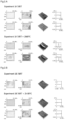
- Figure 2 shows the quantification of the BLRT effect of the composites of table 2 as bar diagrams.
- the bars extending to the right represent the deviation in the positive direction, and the bars extending in the left direction represent the deviation in the negative direction.
- the two bars for samples 2, 3 and 4 each represent a comparison of the maximum deviation for the sample with a material with a discontinuous surface (with filter) and without a material with a discontinuous surface (without filter).
- Sample 1A only shows the maximum deviation of the sample without a material with a discontinuous surface (without filter) and 1B only shows the maximum deviation of the sample with a material with a discontinuous surface (with filter).
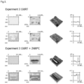
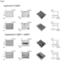
- Figure 3 shows the appearance of the adhesive bead after disassembly of composite No. 4 and the removal of the net.
- the adhesive bead was cut using a metal wire. It is clearly visible, that the adhesive was separated into small portions by the net, thus resulting in a non-continuous interface between the surface of the adhesive and the metal plate.
- Sikaflex ® -250 MKV3i1 was used as adhesive and the adhesive was pressed to a thickness of 2mm.
- a DVD pad featuring a PU rigid foam was applied as a second surface layer, instead of a second metal layer.
- test strips were prepared with a 9x20 cm metal layer.
- the adhesive beads were applied with an automatic application device on the DVD foam pad (GA Bohemia cz 0511880/00, 9x16 cm), the filter was applied on top of the adhesive beads and then the system was bonded to the metal layer.
- the adhesive was cured for 10 days at 23°C and 50% r.h.
Landscapes
- Laminated Bodies (AREA)
Claims (13)
- Mehrschichtiger Verbundwerkstoff, umfassend zwei Oberflächenschichten mit einer dazwischenliegenden Klebeschicht und eine Schicht aus einem Material mit einer unterbrochenen Oberfläche, wobei sich die Schicht aus dem Material mit einer unterbrochenen Oberfläche zwischen der Oberfläche des Klebstoffs und der Oberfläche von mindestens einer der Oberflächenschichten befindet, sodass die Klebebindung an die Oberfläche der Oberflächenschicht durch eine Vielzahl von kleinen einzelnen Bindungsflächen oder -punkten erfolgt, dadurch gekennzeichnet, dass der Klebstoff einen G-Modul, ermittelt gemäß DIN 54451, von mehr als 2 MPa aufweist, wobei der Klebstoff in der Klebeschicht einen Einkomponentenklebstoff auf Basis von Polyurethan, einen Zweikomponentenklebstoff auf Basis von Polyurethan, einen Einkomponenten- und/oder Zweikomponentenklebstoff auf Basis von silanterminiertem Polyurethan, vorzugsweise einen Einkomponentenklebstoff auf Basis von Polyurethan, umfasst.
- Mehrschichtiger Verbundwerkstoff nach Anspruch 1, wobei das Material mit einer unterbrochenen Oberfläche eine netzartige Geometrie aufweist.
- Mehrschichtiger Verbundwerkstoff nach Anspruch 1 oder 2, wobei jede der zwei Oberflächenschichten eine Metallplatte umfasst, vorzugsweise eine Aluminium- oder Stahlplatte, vorzugsweise mit einer Dicke von etwa 0,3 mm bis etwa 1,5 mm, vorzugsweise von 0,40 mm bis etwa 0,95 mm, besonders bevorzugt von etwa 0,5 bis etwa 0, 75 mm.
- Mehrschichtiger Verbundwerkstoff nach einem der vorstehenden Ansprüche, wobei der Klebstoff in der Klebeschicht einen G-Modul, ermittelt gemäß DIN 54451, von 3 MPa oder mehr aufweist.
- Mehrschichtiger Verbundwerkstoff nach Anspruch 2 oder einem davon abhängigen Anspruch, wobei das Material mit einer netzartigen Geometrie ein Material ist, das aus der Gruppe bestehend aus Polyethylen, Polypropylen, Polyester, Polyamid, aus Cellulose gewonnenen Materialien und/oder aus Fasern gewonnenen Materialien, vorzugsweise Polypropylen, ausgewählt ist.
- Mehrschichtiger Verbundwerkstoff nach einem der vorstehenden Ansprüche, wobei das Material mit einer unterbrochenen Oberfläche eine Geometrie aufweist, die rechteckige Löcher, rautenförmige Löcher, kreisförmige Löcher und/oder rechteckige Streifen horizontal oder vertikal zu der Bindungsrichtung umfasst.
- Mehrschichtiger Verbundwerkstoff nach einem der vorstehenden Ansprüche, wobei die Löcher in dem Material mit einer unterbrochenen Oberfläche eine Abmessung von 2 bis 5 mm in der x-Richtung und eine Größe von 2 bis 5 mm in der y-Richtung aufweisen, wobei die x- und die y-Achse in derselben Ebene liegen.
- Mehrschichtiger Verbundwerkstoff nach einem der vorstehenden Ansprüche, wobei das Material mit einer unterbrochenen Oberfläche ein Gewicht von 100 bis 400 g/m2, vorzugsweise von 150 bis 350 g/m2, aufweist.
- Mehrschichtiger Verbundwerkstoff nach einem der vorstehenden Ansprüche, wobei die Klebeschicht nach dem Härten des Klebstoffs eine Dicke von 1 bis 10 mm, vorzugsweise 1 bis 5 mm, aufweist.
- Verfahren zum Herstellen eines mehrschichtigen Verbundwerkstoffs nach einem der vorstehenden Ansprüche 1 bis 9, umfassend die folgenden Schritte:a) Bereitstellen einer ersten Oberflächenschicht,b) Aufbringen eines Klebstoffs auf eine Oberfläche der ersten Oberflächenschicht,c) Aufbringen eines Materials mit einer unterbrochenen Oberfläche auf die Oberfläche des Klebstoffs gegenüber der ersten Oberflächenschicht,d) Aufbringen einer zweiten Oberflächenschicht auf die Oberfläche des Klebstoffs, sodass das Material mit einer unterbrochenen Oberfläche sandwichartig zwischen dem Klebstoff und der zweiten Oberflächenschicht eingeschlossen ist, unde) Härten des Klebstoffs.
- Verfahren nach Anspruch 10, wobei das Material mit einer unterbrochenen Oberfläche vorab an der Oberfläche der zweiten Oberflächenschicht befestigt wird, bevor die zweite Oberflächenschicht auf die Oberfläche des Klebstoffs aufgebracht wird.
- Mehrschichtiger Verbundwerkstoff, erhältlich durch das Verfahren nach einem der Ansprüche 10 oder 11.
- Verwendung des mehrschichtigen Verbundwerkstoffs nach einem der Ansprüche 1 bis 9 und 12 für Automobilanwendungen, vorzugsweise in Automobildächern.
Applications Claiming Priority (2)
| Application Number | Priority Date | Filing Date | Title |
|---|---|---|---|
| EP17164353 | 2017-03-31 | ||
| PCT/EP2018/058048 WO2018178223A1 (en) | 2017-03-31 | 2018-03-29 | Multilayer composites with reduced bond line read through |
Publications (3)
| Publication Number | Publication Date |
|---|---|
| EP3600870A1 EP3600870A1 (de) | 2020-02-05 |
| EP3600870B1 EP3600870B1 (de) | 2020-12-30 |
| EP3600870B2 true EP3600870B2 (de) | 2025-02-26 |
Family
ID=58606012
Family Applications (1)
| Application Number | Title | Priority Date | Filing Date |
|---|---|---|---|
| EP18712922.6A Active EP3600870B2 (de) | 2017-03-31 | 2018-03-29 | Mehrschichtige verbundwerkstoffe mit reduziertem klebschichtdurchschlagen |
Country Status (2)
| Country | Link |
|---|---|
| EP (1) | EP3600870B2 (de) |
| WO (1) | WO2018178223A1 (de) |
Families Citing this family (1)
| Publication number | Priority date | Publication date | Assignee | Title |
|---|---|---|---|---|
| WO2018178223A1 (en) | 2017-03-31 | 2018-10-04 | Sika Technology Ag | Multilayer composites with reduced bond line read through |
Citations (22)
| Publication number | Priority date | Publication date | Assignee | Title |
|---|---|---|---|---|
| CA822071A (en) † | 1969-09-02 | American Cyanamid Company | Metal laminate | |
| CA962573A (en) † | 1971-02-09 | 1975-02-11 | Robert P. Kreahling (Jr.) | Vibration damping laminates |
| US5585178A (en) † | 1991-12-31 | 1996-12-17 | Minnesota Mining & Manufacturing Company | Composite adhesive tape |
| JPH11158313A (ja) † | 1997-11-28 | 1999-06-15 | Neoex Lab Inc | 発泡性成形体 |
| US6382635B1 (en) † | 2000-03-17 | 2002-05-07 | Sika Corporation | Double walled baffle |
| JP2002249071A (ja) † | 2001-02-23 | 2002-09-03 | Neoex Lab Inc | 中空構造物における中空室充填具 |
| USH2047H1 (en) † | 1999-11-10 | 2002-09-03 | Henkel Corporation | Reinforcement laminate |
| US6602611B1 (en) † | 1998-09-02 | 2003-08-05 | Daimlerchrysler Ag | Bonded multi-layer composite plates and a method for producing multi-layer composite plates |
| US20030176128A1 (en) † | 2002-03-15 | 2003-09-18 | L&L Products, Inc. | Structurally reinforced panels |
| US20040262853A1 (en) † | 2003-06-26 | 2004-12-30 | L&L Products, Inc. | Fastenable member for sealing, baffling or reinforcing and method of forming same |
| US20050081383A1 (en) † | 2003-09-18 | 2005-04-21 | L&L Products, Inc. | System and method employing a porous container for sealing, baffling or reinforcing |
| WO2005073330A1 (en) † | 2004-01-22 | 2005-08-11 | 3M Innovative Properties Company | Adhesive tape for structural bonding |
| US20070032575A1 (en) † | 2005-08-08 | 2007-02-08 | Texas Research International, Inc. | Syntactic foam |
| WO2009015149A1 (en) † | 2007-07-23 | 2009-01-29 | Dow Global Technologies Inc. | Two part polyurethane curable composition having substantially consistent g-modulus across the range of use temperatures |
| US20090056868A1 (en) † | 2007-08-31 | 2009-03-05 | Gm Global Technology Operations, Inc. | Adhesive bonding of vehicle external panels to reduce bond-line read-out |
| US20090068479A1 (en) † | 2007-09-11 | 2009-03-12 | Sika Technology Ag | Moisture-reactive adhesive compositions with very low temperature dependency of the shear modulus |
| US20120298300A1 (en) † | 2009-05-27 | 2012-11-29 | Sika Technology Ag | Moisture-curing compostion with improved initial strength |
| EP2563561B1 (de) † | 2010-04-26 | 2016-01-06 | Sika Technology AG | Expandierbarer einsatz mit flexiblem substrat |
| US20160101599A1 (en) † | 2014-10-09 | 2016-04-14 | Materion Corporation | Metal laminate with metallurgical bonds and reduced density metal core layer and method for making the same |
| WO2016183580A1 (en) † | 2015-05-14 | 2016-11-17 | Zephyros, Inc. | Localized panel stiffener |
| WO2017151981A1 (en) † | 2016-03-02 | 2017-09-08 | Zephyros, Inc. | Non-continuous mesh structures |
| WO2018178223A1 (en) † | 2017-03-31 | 2018-10-04 | Sika Technology Ag | Multilayer composites with reduced bond line read through |
-
2018
- 2018-03-29 WO PCT/EP2018/058048 patent/WO2018178223A1/en not_active Ceased
- 2018-03-29 EP EP18712922.6A patent/EP3600870B2/de active Active
Patent Citations (22)
| Publication number | Priority date | Publication date | Assignee | Title |
|---|---|---|---|---|
| CA822071A (en) † | 1969-09-02 | American Cyanamid Company | Metal laminate | |
| CA962573A (en) † | 1971-02-09 | 1975-02-11 | Robert P. Kreahling (Jr.) | Vibration damping laminates |
| US5585178A (en) † | 1991-12-31 | 1996-12-17 | Minnesota Mining & Manufacturing Company | Composite adhesive tape |
| JPH11158313A (ja) † | 1997-11-28 | 1999-06-15 | Neoex Lab Inc | 発泡性成形体 |
| US6602611B1 (en) † | 1998-09-02 | 2003-08-05 | Daimlerchrysler Ag | Bonded multi-layer composite plates and a method for producing multi-layer composite plates |
| USH2047H1 (en) † | 1999-11-10 | 2002-09-03 | Henkel Corporation | Reinforcement laminate |
| US6382635B1 (en) † | 2000-03-17 | 2002-05-07 | Sika Corporation | Double walled baffle |
| JP2002249071A (ja) † | 2001-02-23 | 2002-09-03 | Neoex Lab Inc | 中空構造物における中空室充填具 |
| US20030176128A1 (en) † | 2002-03-15 | 2003-09-18 | L&L Products, Inc. | Structurally reinforced panels |
| US20040262853A1 (en) † | 2003-06-26 | 2004-12-30 | L&L Products, Inc. | Fastenable member for sealing, baffling or reinforcing and method of forming same |
| US20050081383A1 (en) † | 2003-09-18 | 2005-04-21 | L&L Products, Inc. | System and method employing a porous container for sealing, baffling or reinforcing |
| WO2005073330A1 (en) † | 2004-01-22 | 2005-08-11 | 3M Innovative Properties Company | Adhesive tape for structural bonding |
| US20070032575A1 (en) † | 2005-08-08 | 2007-02-08 | Texas Research International, Inc. | Syntactic foam |
| WO2009015149A1 (en) † | 2007-07-23 | 2009-01-29 | Dow Global Technologies Inc. | Two part polyurethane curable composition having substantially consistent g-modulus across the range of use temperatures |
| US20090056868A1 (en) † | 2007-08-31 | 2009-03-05 | Gm Global Technology Operations, Inc. | Adhesive bonding of vehicle external panels to reduce bond-line read-out |
| US20090068479A1 (en) † | 2007-09-11 | 2009-03-12 | Sika Technology Ag | Moisture-reactive adhesive compositions with very low temperature dependency of the shear modulus |
| US20120298300A1 (en) † | 2009-05-27 | 2012-11-29 | Sika Technology Ag | Moisture-curing compostion with improved initial strength |
| EP2563561B1 (de) † | 2010-04-26 | 2016-01-06 | Sika Technology AG | Expandierbarer einsatz mit flexiblem substrat |
| US20160101599A1 (en) † | 2014-10-09 | 2016-04-14 | Materion Corporation | Metal laminate with metallurgical bonds and reduced density metal core layer and method for making the same |
| WO2016183580A1 (en) † | 2015-05-14 | 2016-11-17 | Zephyros, Inc. | Localized panel stiffener |
| WO2017151981A1 (en) † | 2016-03-02 | 2017-09-08 | Zephyros, Inc. | Non-continuous mesh structures |
| WO2018178223A1 (en) † | 2017-03-31 | 2018-10-04 | Sika Technology Ag | Multilayer composites with reduced bond line read through |
Non-Patent Citations (28)
| Title |
|---|
| ANONYMOUS: "Design Guidance - Service Requirements - Adhesive Type", ADHESIVES DESIGN TOOLKIT, 14 September 2021 (2021-09-14), pages 1 - 3, Retrieved from the Internet <URL:http://www.adhesivestoolkit.com/Toolkits/DesignGuidance/AdhesiveType.xtp> [retrieved on 20211007] † |
| ANONYMOUS: "DIN 54451:1978-11 Prüfung von Metallklebstoffen und Metallklebungen; Zugscher-Versuch zur Ermittlung des Schubspannungs-Gleitungs-Diagramms eines Klebstoffs in einer Klebung", DEUTSCHE NORM, 1 November 1978 (1978-11-01), pages 1 - 5 † |
| Brockmann, Walter et al., "Adhesive Bonding - Materials,Applications and Technology" Wiley-VCH Verlag GmbH & Co.KGaA, 2009 † |
| Casey, Kevin et al., "Expandable Epoxy Foam: A Systematic Approach to Improve Vehicle Performance "SAE Technical Paper Series 2004-01-0243, December 2004 ISSN: 0-7680-1319-4 † |
| English translation of JP2002249071a † |
| English translation of JPH11158313a † |
| Habenicht, Gerd, "Kleben - Grundlagen, Technologies Anwendungen" Germany: Springer Verlag. 2009, Ed. 6th ISBN 978-3-540-85264-3 † |
| Hinnerichs , Terry et al., "Validation of a Viscoelastic Model for Foam Encapsulated Component Response Over a Wide Temperature Range SAND2006-6611C"Sandia National Lab SAND2006-6611C , December 2006 † |
| HUVENERS E.M.P, HERWIJNEN, SOETENS F, HOFMEYER H: "Mechanical shear properties of adhesives", PROCEEDINGS OF THE 10TH INTERNATIONAL CONFERENCE ON ARCHITECTURAL AND AUTOMOTIVE GLASS, 15-18 JUNE 2007, TAMPERE, FINLAND, GLASS PERFORMANCE DAYS, TAMGLASS LTD. OY, 1 January 2007 (2007-01-01), pages 367 - 370 † |
| IPRP for the contested patent † |
| K. SCHNEIDER, LAUKE B., BECKERT W.: "Compression Shear Test (CST) – A Convenient Apparatus for the Estimation of Apparent Shear Strength of Composite Materials", APPLIED COMPOSITE MATERIALS, KLUWER ACADEMIC PUBLISHERS, LONDON, NL, vol. 8, no. 1, 1 January 2001 (2001-01-01), NL, pages 43 - 62, ISSN: 0929-189X, DOI: 10.1023/A:1008919114960 † |
| L-5206 Technical Data Sheet † |
| L-5208 Technical Data Sheet † |
| L-5224 Technical Data Sheet † |
| L-5248 Technical Data Sheet † |
| Obi, Bernard E.. "Polymeric Foams - Structure - Property -Performance" United Kingdom: Elsevier, 07.12.2017 † |
| OIARTZUN MAIALEN A: "Mixed material bonding: effects of the properties of the adhesive on the thermal shape distortion", THESIS UNIVERSITY OF SKÖVDE, 2016, pages 1 - 41 † |
| Overview of materials for Epoxy Cure Resin" † |
| Produktdatenblatt Sika Tack OEM+ (2007) mit offenbartem G-Modul. † |
| Produktdatenblatt Sikaflex -234 (2015) † |
| Russik, Edward M. et al., "Development and Characterization of a New Epoxy Foam Encapsulant as an Able foam Replacement" Sandia Report SAND98-2538,December 1998 † |
| SICOMIN Epoxy Systems, PB 170, PB 250, PB 400, PB 600,Epoxy Systeme zur Herstellung von Zellschäumen,11.02.2009 † |
| TEROSON PU 8594 HMLC (Technical Data Sheet) (published October2016) † |
| TEROSON PU 8630 2HMLC (Technical Data Sheet) (published October2016) † |
| TEROSON-8597 HMLC (Technical Data Sheet) (published February2003) † |
| TEROSTAT 9097 PL HMLC (Technical Data Sheet) (published July 2009) † |
| waybackmachine" documentation † |
| Zalobsky, Anita et al., "Recommendations on Selection and Use of Cavity Reinforcement Materials" SAE Technical Paper Series 1999-01-1672, December 1999 ISSN: 0148-7191 † |
Also Published As
| Publication number | Publication date |
|---|---|
| EP3600870A1 (de) | 2020-02-05 |
| EP3600870B1 (de) | 2020-12-30 |
| WO2018178223A1 (en) | 2018-10-04 |
Similar Documents
| Publication | Publication Date | Title |
|---|---|---|
| EP1802722B1 (de) | Verfahren zur herstellung von montageklebebänder mit einer trägerschicht auf basis von thermisch vernetzten, viskoelastischen acrylaten | |
| US4451518A (en) | Reinforcing member | |
| DE69808484T2 (de) | On-line lackierbare einlage | |
| WO2008000833A1 (de) | Mittels silikon abgedichtete verklebung | |
| EP3600870B2 (de) | Mehrschichtige verbundwerkstoffe mit reduziertem klebschichtdurchschlagen | |
| DE102004003328B4 (de) | Verfahren zum Herstellen eines gewölbten Karosserieelements mit Solarzellen | |
| CN107208441B (zh) | 包括板和至少一个升降轨的设备及其制备方法和用途 | |
| Silvestru et al. | Linear adhesive connections at the edge of laminated glass panes: an experimental study under tensile, compressive and shear loading | |
| JP6731489B2 (ja) | 接着剤接続用アルミニウム合金ストリップ | |
| DE10237322B4 (de) | Anordnung für ein Fahrzeugdach mit zwei verklebten Elementen sowie Herstellungsverfahren dafür | |
| US6447885B1 (en) | Bonding together surfaces | |
| US10479051B2 (en) | Decorative panel | |
| DE202010008964U1 (de) | Hybridbauteil unter Verwendung von Wabenmaterial, insbesondere Wabenpappe | |
| JPH02274615A (ja) | 車窓用ダムラバー | |
| WO2018130719A1 (de) | Kraft- und nutzfahrzeugauflagevorrichtung | |
| DE102008052155A1 (de) | Verfahren zum Herstellen einer Trägerplatte und Trägerplatte | |
| JP2018177963A (ja) | 物品の製造方法および重ね貼り装置 | |
| DE102005044263A1 (de) | Selbstklebendes Verbindungsmittel und Verklebungsverfahren | |
| DE102010004863B4 (de) | Verfahren zum Verkleben eines flächigen Bauteils, insbesondere zum Verkleben von Verkleidungs- und/oder Dekorteilen an einem Karosseriebauteil von Kraftfahrzeugen | |
| CN103429448A (zh) | 窗玻璃的安装构造 | |
| JP2008001058A (ja) | 化粧ボード | |
| DE102018125998B4 (de) | Verfahren zur herstellung einer kunststoff-verbundscheibe | |
| WO2006050927A1 (de) | Verfahren zur herstellung eines verbundglases und verbundglas | |
| JP3257848B2 (ja) | 制振及び制振複合構造体 | |
| JP2018177961A (ja) | 接着シートセットおよび物品の製造方法 |
Legal Events
| Date | Code | Title | Description |
|---|---|---|---|
| STAA | Information on the status of an ep patent application or granted ep patent |
Free format text: STATUS: UNKNOWN |
|
| STAA | Information on the status of an ep patent application or granted ep patent |
Free format text: STATUS: THE INTERNATIONAL PUBLICATION HAS BEEN MADE |
|
| PUAI | Public reference made under article 153(3) epc to a published international application that has entered the european phase |
Free format text: ORIGINAL CODE: 0009012 |
|
| STAA | Information on the status of an ep patent application or granted ep patent |
Free format text: STATUS: REQUEST FOR EXAMINATION WAS MADE |
|
| 17P | Request for examination filed |
Effective date: 20191031 |
|
| AK | Designated contracting states |
Kind code of ref document: A1 Designated state(s): AL AT BE BG CH CY CZ DE DK EE ES FI FR GB GR HR HU IE IS IT LI LT LU LV MC MK MT NL NO PL PT RO RS SE SI SK SM TR |
|
| AX | Request for extension of the european patent |
Extension state: BA ME |
|
| DAV | Request for validation of the european patent (deleted) | ||
| DAX | Request for extension of the european patent (deleted) | ||
| GRAP | Despatch of communication of intention to grant a patent |
Free format text: ORIGINAL CODE: EPIDOSNIGR1 |
|
| STAA | Information on the status of an ep patent application or granted ep patent |
Free format text: STATUS: GRANT OF PATENT IS INTENDED |
|
| INTG | Intention to grant announced |
Effective date: 20200814 |
|
| GRAS | Grant fee paid |
Free format text: ORIGINAL CODE: EPIDOSNIGR3 |
|
| GRAA | (expected) grant |
Free format text: ORIGINAL CODE: 0009210 |
|
| STAA | Information on the status of an ep patent application or granted ep patent |
Free format text: STATUS: THE PATENT HAS BEEN GRANTED |
|
| AK | Designated contracting states |
Kind code of ref document: B1 Designated state(s): AL AT BE BG CH CY CZ DE DK EE ES FI FR GB GR HR HU IE IS IT LI LT LU LV MC MK MT NL NO PL PT RO RS SE SI SK SM TR |
|
| REG | Reference to a national code |
Ref country code: GB Ref legal event code: FG4D |
|
| REG | Reference to a national code |
Ref country code: AT Ref legal event code: REF Ref document number: 1349513 Country of ref document: AT Kind code of ref document: T Effective date: 20210115 |
|
| REG | Reference to a national code |
Ref country code: DE Ref legal event code: R096 Ref document number: 602018011363 Country of ref document: DE |
|
| REG | Reference to a national code |
Ref country code: IE Ref legal event code: FG4D |
|
| PG25 | Lapsed in a contracting state [announced via postgrant information from national office to epo] |
Ref country code: RS Free format text: LAPSE BECAUSE OF FAILURE TO SUBMIT A TRANSLATION OF THE DESCRIPTION OR TO PAY THE FEE WITHIN THE PRESCRIBED TIME-LIMIT Effective date: 20201230 Ref country code: FI Free format text: LAPSE BECAUSE OF FAILURE TO SUBMIT A TRANSLATION OF THE DESCRIPTION OR TO PAY THE FEE WITHIN THE PRESCRIBED TIME-LIMIT Effective date: 20201230 Ref country code: NO Free format text: LAPSE BECAUSE OF FAILURE TO SUBMIT A TRANSLATION OF THE DESCRIPTION OR TO PAY THE FEE WITHIN THE PRESCRIBED TIME-LIMIT Effective date: 20210330 Ref country code: GR Free format text: LAPSE BECAUSE OF FAILURE TO SUBMIT A TRANSLATION OF THE DESCRIPTION OR TO PAY THE FEE WITHIN THE PRESCRIBED TIME-LIMIT Effective date: 20210331 |
|
| REG | Reference to a national code |
Ref country code: AT Ref legal event code: MK05 Ref document number: 1349513 Country of ref document: AT Kind code of ref document: T Effective date: 20201230 |
|
| PG25 | Lapsed in a contracting state [announced via postgrant information from national office to epo] |
Ref country code: BG Free format text: LAPSE BECAUSE OF FAILURE TO SUBMIT A TRANSLATION OF THE DESCRIPTION OR TO PAY THE FEE WITHIN THE PRESCRIBED TIME-LIMIT Effective date: 20210330 Ref country code: LV Free format text: LAPSE BECAUSE OF FAILURE TO SUBMIT A TRANSLATION OF THE DESCRIPTION OR TO PAY THE FEE WITHIN THE PRESCRIBED TIME-LIMIT Effective date: 20201230 Ref country code: SE Free format text: LAPSE BECAUSE OF FAILURE TO SUBMIT A TRANSLATION OF THE DESCRIPTION OR TO PAY THE FEE WITHIN THE PRESCRIBED TIME-LIMIT Effective date: 20201230 |
|
| REG | Reference to a national code |
Ref country code: NL Ref legal event code: MP Effective date: 20201230 |
|
| PG25 | Lapsed in a contracting state [announced via postgrant information from national office to epo] |
Ref country code: HR Free format text: LAPSE BECAUSE OF FAILURE TO SUBMIT A TRANSLATION OF THE DESCRIPTION OR TO PAY THE FEE WITHIN THE PRESCRIBED TIME-LIMIT Effective date: 20201230 |
|
| REG | Reference to a national code |
Ref country code: LT Ref legal event code: MG9D |
|
| PG25 | Lapsed in a contracting state [announced via postgrant information from national office to epo] |
Ref country code: LT Free format text: LAPSE BECAUSE OF FAILURE TO SUBMIT A TRANSLATION OF THE DESCRIPTION OR TO PAY THE FEE WITHIN THE PRESCRIBED TIME-LIMIT Effective date: 20201230 Ref country code: RO Free format text: LAPSE BECAUSE OF FAILURE TO SUBMIT A TRANSLATION OF THE DESCRIPTION OR TO PAY THE FEE WITHIN THE PRESCRIBED TIME-LIMIT Effective date: 20201230 Ref country code: PT Free format text: LAPSE BECAUSE OF FAILURE TO SUBMIT A TRANSLATION OF THE DESCRIPTION OR TO PAY THE FEE WITHIN THE PRESCRIBED TIME-LIMIT Effective date: 20210430 Ref country code: SK Free format text: LAPSE BECAUSE OF FAILURE TO SUBMIT A TRANSLATION OF THE DESCRIPTION OR TO PAY THE FEE WITHIN THE PRESCRIBED TIME-LIMIT Effective date: 20201230 Ref country code: CZ Free format text: LAPSE BECAUSE OF FAILURE TO SUBMIT A TRANSLATION OF THE DESCRIPTION OR TO PAY THE FEE WITHIN THE PRESCRIBED TIME-LIMIT Effective date: 20201230 Ref country code: EE Free format text: LAPSE BECAUSE OF FAILURE TO SUBMIT A TRANSLATION OF THE DESCRIPTION OR TO PAY THE FEE WITHIN THE PRESCRIBED TIME-LIMIT Effective date: 20201230 |
|
| PG25 | Lapsed in a contracting state [announced via postgrant information from national office to epo] |
Ref country code: AT Free format text: LAPSE BECAUSE OF FAILURE TO SUBMIT A TRANSLATION OF THE DESCRIPTION OR TO PAY THE FEE WITHIN THE PRESCRIBED TIME-LIMIT Effective date: 20201230 Ref country code: PL Free format text: LAPSE BECAUSE OF FAILURE TO SUBMIT A TRANSLATION OF THE DESCRIPTION OR TO PAY THE FEE WITHIN THE PRESCRIBED TIME-LIMIT Effective date: 20201230 |
|
| REG | Reference to a national code |
Ref country code: DE Ref legal event code: R026 Ref document number: 602018011363 Country of ref document: DE |
|
| PG25 | Lapsed in a contracting state [announced via postgrant information from national office to epo] |
Ref country code: IS Free format text: LAPSE BECAUSE OF FAILURE TO SUBMIT A TRANSLATION OF THE DESCRIPTION OR TO PAY THE FEE WITHIN THE PRESCRIBED TIME-LIMIT Effective date: 20210430 |
|
| PLBI | Opposition filed |
Free format text: ORIGINAL CODE: 0009260 |
|
| PLAX | Notice of opposition and request to file observation + time limit sent |
Free format text: ORIGINAL CODE: EPIDOSNOBS2 |
|
| PG25 | Lapsed in a contracting state [announced via postgrant information from national office to epo] |
Ref country code: AL Free format text: LAPSE BECAUSE OF FAILURE TO SUBMIT A TRANSLATION OF THE DESCRIPTION OR TO PAY THE FEE WITHIN THE PRESCRIBED TIME-LIMIT Effective date: 20201230 Ref country code: IT Free format text: LAPSE BECAUSE OF FAILURE TO SUBMIT A TRANSLATION OF THE DESCRIPTION OR TO PAY THE FEE WITHIN THE PRESCRIBED TIME-LIMIT Effective date: 20201230 Ref country code: MC Free format text: LAPSE BECAUSE OF FAILURE TO SUBMIT A TRANSLATION OF THE DESCRIPTION OR TO PAY THE FEE WITHIN THE PRESCRIBED TIME-LIMIT Effective date: 20201230 |
|
| REG | Reference to a national code |
Ref country code: CH Ref legal event code: PL |
|
| 26 | Opposition filed |
Opponent name: L & L PRODUCTS EUROPE S.A.S. Effective date: 20210929 |
|
| PG25 | Lapsed in a contracting state [announced via postgrant information from national office to epo] |
Ref country code: DK Free format text: LAPSE BECAUSE OF FAILURE TO SUBMIT A TRANSLATION OF THE DESCRIPTION OR TO PAY THE FEE WITHIN THE PRESCRIBED TIME-LIMIT Effective date: 20201230 |
|
| REG | Reference to a national code |
Ref country code: BE Ref legal event code: MM Effective date: 20210331 |
|
| PG25 | Lapsed in a contracting state [announced via postgrant information from national office to epo] |
Ref country code: LU Free format text: LAPSE BECAUSE OF NON-PAYMENT OF DUE FEES Effective date: 20210329 Ref country code: LI Free format text: LAPSE BECAUSE OF NON-PAYMENT OF DUE FEES Effective date: 20210331 Ref country code: IE Free format text: LAPSE BECAUSE OF NON-PAYMENT OF DUE FEES Effective date: 20210329 Ref country code: CH Free format text: LAPSE BECAUSE OF NON-PAYMENT OF DUE FEES Effective date: 20210331 Ref country code: FR Free format text: LAPSE BECAUSE OF NON-PAYMENT OF DUE FEES Effective date: 20210331 Ref country code: ES Free format text: LAPSE BECAUSE OF FAILURE TO SUBMIT A TRANSLATION OF THE DESCRIPTION OR TO PAY THE FEE WITHIN THE PRESCRIBED TIME-LIMIT Effective date: 20201230 |
|
| PLBB | Reply of patent proprietor to notice(s) of opposition received |
Free format text: ORIGINAL CODE: EPIDOSNOBS3 |
|
| PG25 | Lapsed in a contracting state [announced via postgrant information from national office to epo] |
Ref country code: SI Free format text: LAPSE BECAUSE OF FAILURE TO SUBMIT A TRANSLATION OF THE DESCRIPTION OR TO PAY THE FEE WITHIN THE PRESCRIBED TIME-LIMIT Effective date: 20201230 |
|
| PG25 | Lapsed in a contracting state [announced via postgrant information from national office to epo] |
Ref country code: IS Free format text: LAPSE BECAUSE OF FAILURE TO SUBMIT A TRANSLATION OF THE DESCRIPTION OR TO PAY THE FEE WITHIN THE PRESCRIBED TIME-LIMIT Effective date: 20210430 |
|
| PG25 | Lapsed in a contracting state [announced via postgrant information from national office to epo] |
Ref country code: BE Free format text: LAPSE BECAUSE OF NON-PAYMENT OF DUE FEES Effective date: 20210331 |
|
| GBPC | Gb: european patent ceased through non-payment of renewal fee |
Effective date: 20220329 |
|
| PG25 | Lapsed in a contracting state [announced via postgrant information from national office to epo] |
Ref country code: GB Free format text: LAPSE BECAUSE OF NON-PAYMENT OF DUE FEES Effective date: 20220329 |
|
| PG25 | Lapsed in a contracting state [announced via postgrant information from national office to epo] |
Ref country code: NL Free format text: LAPSE BECAUSE OF NON-PAYMENT OF DUE FEES Effective date: 20201230 Ref country code: CY Free format text: LAPSE BECAUSE OF FAILURE TO SUBMIT A TRANSLATION OF THE DESCRIPTION OR TO PAY THE FEE WITHIN THE PRESCRIBED TIME-LIMIT Effective date: 20201230 |
|
| PG25 | Lapsed in a contracting state [announced via postgrant information from national office to epo] |
Ref country code: SM Free format text: LAPSE BECAUSE OF FAILURE TO SUBMIT A TRANSLATION OF THE DESCRIPTION OR TO PAY THE FEE WITHIN THE PRESCRIBED TIME-LIMIT Effective date: 20201230 Ref country code: HU Free format text: LAPSE BECAUSE OF FAILURE TO SUBMIT A TRANSLATION OF THE DESCRIPTION OR TO PAY THE FEE WITHIN THE PRESCRIBED TIME-LIMIT; INVALID AB INITIO Effective date: 20180329 |
|
| APAH | Appeal reference modified |
Free format text: ORIGINAL CODE: EPIDOSCREFNO |
|
| APBM | Appeal reference recorded |
Free format text: ORIGINAL CODE: EPIDOSNREFNO |
|
| APBP | Date of receipt of notice of appeal recorded |
Free format text: ORIGINAL CODE: EPIDOSNNOA2O |
|
| APAH | Appeal reference modified |
Free format text: ORIGINAL CODE: EPIDOSCREFNO |
|
| APBQ | Date of receipt of statement of grounds of appeal recorded |
Free format text: ORIGINAL CODE: EPIDOSNNOA3O |
|
| PG25 | Lapsed in a contracting state [announced via postgrant information from national office to epo] |
Ref country code: MK Free format text: LAPSE BECAUSE OF FAILURE TO SUBMIT A TRANSLATION OF THE DESCRIPTION OR TO PAY THE FEE WITHIN THE PRESCRIBED TIME-LIMIT Effective date: 20201230 |
|
| PG25 | Lapsed in a contracting state [announced via postgrant information from national office to epo] |
Ref country code: TR Free format text: LAPSE BECAUSE OF FAILURE TO SUBMIT A TRANSLATION OF THE DESCRIPTION OR TO PAY THE FEE WITHIN THE PRESCRIBED TIME-LIMIT Effective date: 20201230 |
|
| APBU | Appeal procedure closed |
Free format text: ORIGINAL CODE: EPIDOSNNOA9O |
|
| PG25 | Lapsed in a contracting state [announced via postgrant information from national office to epo] |
Ref country code: MT Free format text: LAPSE BECAUSE OF FAILURE TO SUBMIT A TRANSLATION OF THE DESCRIPTION OR TO PAY THE FEE WITHIN THE PRESCRIBED TIME-LIMIT Effective date: 20201230 |
|
| PUAH | Patent maintained in amended form |
Free format text: ORIGINAL CODE: 0009272 |
|
| STAA | Information on the status of an ep patent application or granted ep patent |
Free format text: STATUS: PATENT MAINTAINED AS AMENDED |
|
| 27A | Patent maintained in amended form |
Effective date: 20250226 |
|
| AK | Designated contracting states |
Kind code of ref document: B2 Designated state(s): AL AT BE BG CH CY CZ DE DK EE ES FI FR GB GR HR HU IE IS IT LI LT LU LV MC MK MT NL NO PL PT RO RS SE SI SK SM TR |
|
| REG | Reference to a national code |
Ref country code: DE Ref legal event code: R102 Ref document number: 602018011363 Country of ref document: DE |
|
| PGFP | Annual fee paid to national office [announced via postgrant information from national office to epo] |
Ref country code: DE Payment date: 20250218 Year of fee payment: 8 |