EP3600860B1 - Vorrichtung zum thermischen härten eines linsenformenden materials - Google Patents
Vorrichtung zum thermischen härten eines linsenformenden materials Download PDFInfo
- Publication number
- EP3600860B1 EP3600860B1 EP18716672.3A EP18716672A EP3600860B1 EP 3600860 B1 EP3600860 B1 EP 3600860B1 EP 18716672 A EP18716672 A EP 18716672A EP 3600860 B1 EP3600860 B1 EP 3600860B1
- Authority
- EP
- European Patent Office
- Prior art keywords
- mold
- tray
- lens
- plate
- top surface
- Prior art date
- Legal status (The legal status is an assumption and is not a legal conclusion. Google has not performed a legal analysis and makes no representation as to the accuracy of the status listed.)
- Active
Links
Images

Classifications
-
- B—PERFORMING OPERATIONS; TRANSPORTING
- B29—WORKING OF PLASTICS; WORKING OF SUBSTANCES IN A PLASTIC STATE IN GENERAL
- B29D—PRODUCING PARTICULAR ARTICLES FROM PLASTICS OR FROM SUBSTANCES IN A PLASTIC STATE
- B29D11/00—Producing optical elements, e.g. lenses or prisms
- B29D11/00009—Production of simple or compound lenses
- B29D11/00038—Production of contact lenses
- B29D11/00125—Auxiliary operations, e.g. removing oxygen from the mould, conveying moulds from a storage to the production line in an inert atmosphere
- B29D11/00134—Curing of the contact lens material
-
- B—PERFORMING OPERATIONS; TRANSPORTING
- B29—WORKING OF PLASTICS; WORKING OF SUBSTANCES IN A PLASTIC STATE IN GENERAL
- B29C—SHAPING OR JOINING OF PLASTICS; SHAPING OF MATERIAL IN A PLASTIC STATE, NOT OTHERWISE PROVIDED FOR; AFTER-TREATMENT OF THE SHAPED PRODUCTS, e.g. REPAIRING
- B29C33/00—Moulds or cores; Details thereof or accessories therefor
- B29C33/30—Mounting, exchanging or centering
- B29C33/305—Mounting of moulds or mould support plates
-
- B—PERFORMING OPERATIONS; TRANSPORTING
- B29—WORKING OF PLASTICS; WORKING OF SUBSTANCES IN A PLASTIC STATE IN GENERAL
- B29D—PRODUCING PARTICULAR ARTICLES FROM PLASTICS OR FROM SUBSTANCES IN A PLASTIC STATE
- B29D11/00—Producing optical elements, e.g. lenses or prisms
- B29D11/00009—Production of simple or compound lenses
- B29D11/00038—Production of contact lenses
- B29D11/00125—Auxiliary operations, e.g. removing oxygen from the mould, conveying moulds from a storage to the production line in an inert atmosphere
- B29D11/00173—Conveying moulds
- B29D11/00182—Conveying moulds using carrier plates
-
- B—PERFORMING OPERATIONS; TRANSPORTING
- B29—WORKING OF PLASTICS; WORKING OF SUBSTANCES IN A PLASTIC STATE IN GENERAL
- B29K—INDEXING SCHEME ASSOCIATED WITH SUBCLASSES B29B, B29C OR B29D, RELATING TO MOULDING MATERIALS OR TO MATERIALS FOR MOULDS, REINFORCEMENTS, FILLERS OR PREFORMED PARTS, e.g. INSERTS
- B29K2823/00—Use of polyalkenes or derivatives thereof as mould material
- B29K2823/10—Polymers of propylene
- B29K2823/12—PP, i.e. polypropylene
-
- B—PERFORMING OPERATIONS; TRANSPORTING
- B29—WORKING OF PLASTICS; WORKING OF SUBSTANCES IN A PLASTIC STATE IN GENERAL
- B29K—INDEXING SCHEME ASSOCIATED WITH SUBCLASSES B29B, B29C OR B29D, RELATING TO MOULDING MATERIALS OR TO MATERIALS FOR MOULDS, REINFORCEMENTS, FILLERS OR PREFORMED PARTS, e.g. INSERTS
- B29K2905/00—Use of metals, their alloys or their compounds, as mould material
- B29K2905/02—Aluminium
Definitions
- the invention relates to an apparatus for the thermal curing of a lens-forming material contained in a lens mold to form a contact lens, such as a soft contact lens.
- ophthalmic lenses in particular contact lenses such as soft contact lenses
- production of ophthalmic lenses is typically performed with the aid of molds comprising two mold halves, a male mold half and a female mold half.
- a lens-forming material is introduced into one of the two mold halves, for example into the female mold half, and the mold halves are then mated.
- the lens-forming material is thereafter cured to form the contact lens, which is subsequently demolded for further handling the contact lens.
- US 2015/0147425 A1 discloses a method of producing contact lenses with the aid of a lens mold carrier to which mold units comprising re-usable mold halves typically made of glass are mounted. Such re-usable glass mold halves are expensive and are not suitable for thermal curing of the lens-forming material.
- Inexpensive mold halves may be produced through injection-molding.
- Materials which are particularly suitable for injection-molding are injection-moldable plastics, such as polyolefines, for example polypropylene.
- polypropylene mold halves may deform as the lens-forming material shrinks during curing, so that the mold halves cannot be reused.
- no excess lens-forming material is allowed to flow into the mold cavity. Therefore, the extent of shrinkage of the lens-forming material must be kept small in order to produce contact lenses having the desired geometry and optical power.
- the terms “upper/above” and “lower/below” are defined in relation to a tray on which a mold support and a lens mold are arranged.
- an apparatus for thermal curing of a lens-forming material contained in a lens mold to form an ophthalmic lens, in particular a contact lens, such as a soft contact lens is suggested.
- the apparatus comprises:
- the lens mold is arranged spaced apart from the tray by a clearance distance.
- the mold support is a separate piece and the fastener is a resilient latch removably fixing the mold support to the tray at the fixation opening.
- the mold support is a ring comprising an annular ring body and the latch.
- the latch extends from the annular ring body into the fixation opening of the tray and fixedly engages the tray.
- the support surface is an annular top surface of the annular ring body.
- the annular top surface has a top surface inner diameter and a top surface outer diameter.
- the bearing surface of the lens mold is an annular abutment surface arranged on an underside of the lens mold.
- the annular abutment surface has an abutment surface inner diameter and an abutment surface outer diameter.
- the abutment surface inner diameter of the lens mold is smaller than the top surface inner diameter of the annular ring body and the abutment surface outer diameter of the lens mold is larger than the top surface outer diameter of the annular ring body.
- the positioning guide comprises a conical surface arranged at an outer peripheral portion of the annular ring body.
- the conical surface tapers inwardly with increasing distance from the tray.
- the lens mold further comprises a centering flange for engaging the conical surface of the annular ring body in order to align the annular abutment surface of the lens mold with the annular top surface of the annular ring body during arrangement of the lens mold on the ring.
- the upper end of the conical surface merges with the annular top surface at an outer edge thereof having the top surface outer diameter.
- the lower end of the conical surface has a lower end conical surface diameter larger than the top surface outer diameter.
- the centering flange of the lens mold has a flange inner diameter which is larger than the lower end conical surface diameter.
- the mold support comprises a plate having a plate base surface resting on an upper surface of the tray, and the latch.
- the latch extends from the plate into the fixation opening of the tray and fixedly engages the tray.
- the lens mold comprises a mold base part and a mold top part.
- the assembled mold base part and mold top part together form the lens mold.
- the mold base part comprises a centering flange projecting radially outwardly and forming the outer boundary of the mold base part.
- the positioning guide comprises at least three centering pins arranged on the plate top surface at different locations such that they enclose the centering flange of the mold base part, thereby defining the predetermined position of the lens mold relative to the tray.
- the mold base part further comprises a tab extending radially outwardly from the centering flange.
- the positioning guide further comprises at least one pair of positioning pins arranged at predetermined positions on the plate top surface to determine the angular position of the tab of the mold base part.
- the fixation opening of the tray is a disk-shaped mounting hole and the tray further comprises an additional disk-shaped passage hole.
- the plate comprises first and second disk-shaped passage holes, with the first passage hole of the plate being aligned with the passage hole of the tray and the second passage hole of the plate being aligned with the mounting hole of the tray.
- the tray comprises a passage hole and the plate comprises a through-hole.
- the through-hole of the plate is arranged superimposed with the passage hole of the tray.
- the apparatus comprises a plurality of plates adjacently arranged on the same tray.
- the plastic mold support can be made as a separate piece which can be easily fixed to the tray at the fixation opening of the tray, for example by means of a resilient latch of the mold support, thus enabling an easy and quick mounting or removal of the mold support to the tray (for example in case the mold supports must be mounted to the tray or must be removed from the tray, for example during replacement).
- Placement of the lens mold on the ring-shaped mold support may be further facilitated in case the ring-shaped mold support comprises a conical centering surface at an outer peripheral portion of the annular ring body of the ring-shaped mold support. In particular, this conical surface merges with the annular top surface on which the bearing surface of the lens mold rests.
- the lens mold comprises a centering flange extending downwardly in a direction towards the tray. During placement of the lens mold on the mold support, in case of a small positional misalignment the centering flange of the mold may engage the conical surface of the ring-shaped mold support and thus assists in guiding the lens mold to be aligned with the mold support, so that the lens mold comes to properly rest on the mold support.
- the plastic mold support comprises a plate having a plate base surface resting on the upper surface of the tray.
- the latch extends from the plate into the fixation opening of the tray thus fixing the (plastic) plate to the tray.
- the plate design also renders production of the mold support easy and inexpensive due to the simple shape of the plate.
- the plate may also be produced through injection molding and can be easily attached or removed from the tray, which is advantageous when the plate has to be mounted to the tray or has to be removed (e.g. for replacement).
- the molds may be directly arranged on the upper surface of the plastic plate so that the plate thickness represents the clearance distance C by which the molds are arranged spaced from the tray.
- the mold base part may comprise a tab and the plate may comprise at least one pair of positioning pins.
- the mold is then arranged on the plastic plate such that the tab of the mold base part extends between the two positioning pins of the pair.
- the (angular) orientation of the mold is determined, which may be of particular advantage as a high number of molds is to be arranged on the tray or the plastic plate, respectively, so that collisions or overlapping of mold portions of adjacently arranged molds can be avoided.
- the fixation opening of the tray may be embodied as one or more disk-shaped mounting holes, and the tray may further comprise one or more additional disk-shaped passage holes.
- the plate may comprises first and second disk-shaped passage holes, with the first passage hole(s) of the plate being aligned with the passage hole(s) of the tray and the second passage hole(s) of the plate being aligned with the mounting hole(s) of the tray in order to improve the flow of heated air and the homogeneous curing of the lens-forming material.
- the mold support it is particularly advantageous to have a stack of trays with mold supports fixed to the respective trays and lens molds arranged on the mold supports, with the trays being stacked one above the other in the stack and being separated by spacers. This further improves the efficiency of the production process, since such stack of trays further increases the number of lens molds which can be simultaneously exposed to heat, thus increasing the number of lenses which can be simultaneously produced.
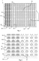
- Fig. 1 shows a first embodiment of an apparatus 1 according to the invention for thermal curing of a lens-forming material contained in a lens mold 10 (of which only a mold base part 100 is visible).
- Lens mold 10 is arranged on a mold support which is fixed to a tray 30.
- Tray 30 is made of metal, for example aluminum, or is made of any other suitable metal.
- the shape of the tray is generally rectangular, with the edges of the tray 30 being bent downwardly. At one corner (upper left corner in Fig. 1 ) the rectangular tray 30 has a cut-away portion. This cut-away portion forms a reference for identification of the rotational orientation of the tray 30 which may be helpful in the automated handling of tray 30.
- a number of supporting webs are arranged at the underside of tray 30, some of them being arranged to run in the horizontal direction (one of them being indicated in Fig. 1 by reference sign 35) while others being arranged to run perpendicular thereto. These supporting webs serve for increasing rigidity and stiffness of tray 30 and are secured to tray 30 with the aid of screws (not shown) screwed through small holes 36 provided in the tray 30.
- Tray 30 has an upper surface 32 and comprises a plurality of fixation openings embodied as disk-shaped mounting holes 31 at which mold supports are fixed to the tray 30.
- tray 30 comprises a plurality of disk-shaped passage holes 34 which are arranged offset relative to the disk-shaped mounting holes 31 at which the mold supports are fixed to the tray 30.
- the mold supports are embodied as rings 20 which are manufactured as separate pieces made of plastic, for example a polyolefine such as polypropylene.
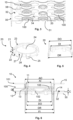
- Ring 20 (the mold support) is shown in more detail.
- Ring 20 comprises an annular ring body 21 as well as a plurality of downwardly extending flexible latches 25.
- Annular ring body 21 has a bottom surface 22 and an annular top surface 23, and defines a central hole 24 surrounded by the annular ring body 21.
- Annular ring body 21 has a height H extending from the bottom surface 22 to the annular top surface 23.
- Annular top surface 23 has a top surface inner diameter DI and a top surface outer diameter DO.
- a conical surface 27 of the annular ring body 21 merges with the annular top surface 23 at an outer edge 28 of the annular top surface 23. Accordingly, conical surface 27 at its upper end has an outer diameter corresponding to the outer diameter DO of the annular top surface 23, while at its lower end it has a larger diameter DR corresponding to the outer diameter of the annular ring body 21.
- latches 25 are introduced from above into the disk-shaped mounting holes 31 of tray 30, whereupon ring 20 is lowered until the bottom surface 22 of annular ring body 21 abuts against the upper surface 32 of tray 30. Latches 25 then form a snap-fit with the tray 30, thus fixing ring 20 to the tray 30 at the disk-shaped mounting hole 31.
- ring 20 projects upwardly from the upper surface 32 of tray 30 by the height H of the annular ring body 21.
- This state where the ring 20 is mounted to the tray 30 at the disk-shaped mounting hole 31 is shown in Fig. 1, Fig. 2 and Fig. 3 at those locations where only the ring 20 is shown mounted to the tray 30.
- lens mold 10 comprises the mold base part 100 and the mold top part 101 mated to the mold base part 100 to form the mold cavity 102 defining the shape of the contact lens to be formed.
- a lens-forming material is dispensed into the concave lens-forming portion of mold base part 100.
- excess lens-forming material is displaced into an annular overflow channel 103 and the mold cavity 102 is sealed.
- Lens mold 10 further comprises a base surface 12 arranged on mold base part 100, and an annular abutment surface 11 arranged on an underside of mold base part 100.
- Annular abutment surface 11 is arranged at a predetermined distance D above the base surface 12 and has an abutment surface inner diameter Al and an abutment surface outer diameter AO.
- a centering flange 13 is arranged on the mold base part 100 and extends downwardly from the annular abutment surface 11 to the base surface 12.
- Mold base part 100 is provided with a tab 14 and mold top part 101 is provided with a tab 15, too. These tabs 14, 15 facilitate handling of the mold parts 100, 101. As can be seen best in Fig. 2 and Fig.
- the distance between adjacent mounting holes 31 of the tray 30 is chosen such that the tabs 14 of the mold base parts 100 of the lens molds 10 arranged on adjacent rings 20 cannot collide. This holds similarly for the tabs 15 of the mold top parts 101 of the lens molds 10 arranged on adjacent rings 20.
- annular abutment surface 11 on the underside of mold base part 100 of lens mold 10 rests on annular top surface 23 of the annular ring body 21 of ring 20 in a manner such that the base surface 12 is arranged at a clearance distance C above the upper surface 32 of tray 30.
- this clearance distance C may be in the range of 0.5 mm to 5 mm, and is the difference between the height H of the annular ring body 21 of the ring 20 and the predetermined distance D which the annular abutment surface 11 is arranged above the base surface 12. Accordingly, the arrangement of the lens mold 10 at the clearance distance C above the upper surface 32 of the tray 30 can be achieved by a suitable choice of the height H of the annular ring body 21 of the ring 20 and the predetermined distance D between the base surface 12 and the abutment surface 11 of the mold base part 100 of lens mold 10.
- the abutment surface inner diameter AI of the abutment surface 11 of lens mold 10 is smaller than the top surface inner diameter DI of the top surface 23 of the annular ring body 21.
- the abutment surface outer diameter AO of the abutment surface 11 of lens mold 10 is larger than the top surface outer diameter DO of the top surface 23 of annular ring body 21. This allows for a proper arrangement of the lens mold 10 on the ring 20.
- an inner diameter FI of the centering flange 13 is larger than the diameter DR of the lower end of the conical surface 27 which corresponds to the outer diameter of the annular ring body 21 in the embodiment shown.
- the central hole 24 defined by the annular ring body 21 is aligned with the mounting hole 31 of the tray 30.
- tray 30 is provided having a number of, for example, two hundred and fifty-six mounting holes 31.
- a corresponding number of rings 20 are fixed to the tray 30 at the mounting holes 31 with the aid of the latches 25.
- a lens mold 10 containing lens-forming material is placed, and in case of small misalignments during placement of the lens molds 10 on the rings 20 the centering flange 13 may come into contact with the conical surface 27 of the annular ring body 21 of ring 20.
- the lens mold 10 is thus guided onto the ring 20 and is properly aligned with the respective ring 20.
- the tray 30 is ready for being placed in an oven for thermal curing of the lens-forming material.
- the apparatus according to the invention may comprise a stack of trays comprising between twenty and thirty individual trays 30.
- the individual trays 30 of the stack are arranged spaced apart from each other with the aid of spacers 38 which are mounted to the respective tray 30 and which allow for easy stacking of the individual trays 30.
- Any suitable spacers known in the art can be used for this purpose and, accordingly, the spacers 38 are not described in more detail.
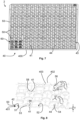
- Fig. 7 shows a second embodiment of the apparatus 2 according to the invention. Some aspects discussed in connection with the first embodiment also hold for the second embodiment, so that these aspects are not discussed here again.
- a tray 40 comprises a frame 400 and a number of supporting webs (not shown) on which metal sheets 401 (see Fig. 8 ) are arranged, which are supported by the frame 400 and by the webs (not shown), and which are retained thereon with the aid of screws 402 and washers 403.
- Frame 400, the supporting webs (not shown) as well as the metal sheets 401 may be made from aluminum to provide for sufficient rigidity and stiffness while at the same time being of light weight.
- an upper surface 42 of the tray 40 is formed that extends in a common plane.
- Tray 40 comprises a plurality of fixation openings embodied as disk-shaped mounting holes 41 (formed in the metal sheets 401) for fixing the mold support to the tray 40 at the mounting holes 41.
- tray 40 comprises a number of disk-shaped passage holes 44 (also formed in the metal sheets 401) which - in the embodiment shown - are larger in diameter than the mounting holes 41.
- two hundred and fifty-six disk-shaped passage holes 44 may be provided in the tray 40.
- Plastic plate 50 has a plate base surface 51 and a plate top surface 52, as can be seen best in Fig. 8 .
- the plate base surface 51 rests on the upper surface 42 of the tray 40 and has a plate thickness T.
- Plate 50 further comprises a plurality of first disk-shaped passage holes 54 and a plurality of second disk-shaped passage holes 58. At the walls of some of the second disk-shaped passage holes 58, latches 53 extend downwardly from the plastic plate 50.
- the latches 53 of plate 50 are introduced into the mounting holes 41 of tray 40, whereupon plate 50 is further moved downwards towards tray 40 until the plate base surface 51 comes to rest on the upper surface 42 of tray 40.
- the latches 53 engage the tray 40 at the mounting holes 41 through a snap-fit connection, thus removably fixing the plate 50 to the tray 40.
- This state is shown in Fig. 8 , and it can also be seen there that the first disk-shaped passage holes 54 of plate 50 are aligned with the passage holes 44 of tray 40 while the second disk-shaped passage holes 58 of plate 50 are aligned with the mounting holes 41 of tray 40.
- centering pins 55 are arranged on the plate top surface 52 around each of the first disk-shaped passage holes 54.
- the centering pins 55 project upwardly from the plate top surface 52 and may have a conical surface 56.
- two pairs of positioning pins 57 are arranged on the plate top surface 52 at different first and second angular positions, these angular positions being different by 90° (ninety degrees).
- the positioning pins 57 may also have a conical surface.
- the lens mold 60 again comprises a mold base part 600 and a mold top part 601 which are mated and enclose a mold cavity 602 containing a lens-forming material to be cured to form a contact lens.
- Mold base part 600 comprises a centering flange 64 projecting radially outwardly and forming the outer boundary of mold base part 600.
- a base surface 61 of mold base part 600 rests on the plate top surface 52, so that plate top surface 52 of plate 50 forms the support surface of the mold support and base surface 61 of mold base part 600 forms the bearing surface of the mold 60.
- the plate thickness T thus represents the clearance distance C by which the lens mold 60 is arranged spaced apart from the tray 40.
- Mold base part 600 further comprises an elongated tab 65 which helps in placing the lens mold 60 in a well-defined rotational orientation on plate 50, as is discussed in more detail below.
- mold base part 600 Upon placing lens mold 60 on the plate top surface 52, mold base part 600 must have a rotational orientation such that the elongated tab 65 fits between one of the two pairs of positioning pins 57, so that the positioning pins 57 determine the first and second angular positions of the elongated tab 65.
- the mold base part 600 must be placed on the plate top surface 52 such that the centering flange 64 is enclosed by the centering pins 55.
- the conical surfaces 56 of the centering pins 55 assist in centering the mold base part 600 (and thus in centering the mold 60) so that it comes to rest at the desired predetermined position.
- the elongated tab 65 may be guided by the conical surfaces of the positioning pins 57.
- tray 40 is ready for being placed in the oven for curing of the lens-forming material contained in the mold cavities 602 of the lens molds 60 to form the contact lenses.
- the apparatus according to the invention may comprise a stack of trays comprising between twenty and thirty individual trays 40.
- the individual trays 40 of the stack are arranged spaced apart from each other with the aid of spacers 43 (see Fig. 7 or Fig. 9 ), which are mounted to the respective tray 40 and which allow for easy stacking of the individual trays 40.
- spacers 43 Any suitable spacers known in the art can be used for this purpose and, accordingly, the spacers 43 are not described in more detail.
Landscapes
- Engineering & Computer Science (AREA)
- Mechanical Engineering (AREA)
- Health & Medical Sciences (AREA)
- Manufacturing & Machinery (AREA)
- Ophthalmology & Optometry (AREA)
- Moulds For Moulding Plastics Or The Like (AREA)
- Eyeglasses (AREA)
- Packaging Frangible Articles (AREA)
Claims (16)
- Vorrichtung (1, 2) zum thermischen Härten eines linsenbildenden Materials, das in einem Linsenformwerkzeug (10, 60) enthalten ist, um eine Kontaktlinse, wie eine weiche Kontaktlinse, zu bilden, wobei die Vorrichtung umfasst:- eine Ablage (30, 40), die aus Metall, beispielsweise Aluminium, gefertigt ist, wobei die Ablage eine Fixieröffnung (31, 41) hat,- einen Formwerkzeugträger (20, 50), der aus Kunststoff gefertigt ist, beispielsweise einem Polyolefin, wie Polypropylen,wobei der Formwerkzeugträger (20, 50) einen an der Ablage (30, 40) an der Fixieröffnung (31, 41) fixierten Befestiger (25, 53) aufweist, und der Formwerkzeugträger (20, 50) an der Ablage (30, 40) fixiert wird, wobei der Formwerkzeugträger (20, 50) des Weiteren eine Positionierungsführung (27, 55) aufweist, die ausgestaltet ist, um ein Linsenformwerkzeug (10, 60) auf den Formwerkzeugträger (20, 50) und in eine vorbestimmte Position relativ zu der Ablage (30, 40) zu führen,und wobei der Formwerkzeugträger (20, 50) des Weiteren eine Trägeroberfläche (23, 52) aufweist, und- ein Linsenformwerkzeug (10, 60), das aus einem spritzgießbaren Kunststoffmaterial gefertigt ist, beispielsweise einem Polyolefin, wie Polypropylen, und auf einem Formwerkzeugträger (20, 50) angeordnet ist, wobei das Linsenformwerkzeug (10, 60) eine Auflageoberfläche (11, 61) aufweist, die auf der Trägeroberfläche (23, 52) des Formwerkzeugträgers (20, 50) ruht,wobei das Linsenformwerkzeug (10, 60) um einen Freiraumabstand (C, T) beabstandet von der Ablage (30, 40) angeordnet ist.
- Vorrichtung (1, 2) nach Anspruch 1, wobei der Formwerkzeugträger (20, 50) ein separates Teil ist, und wobei der Befestiger ein elastischer Riegel (25, 53) ist, der den Formwerkzeugträger (20, 50) abnehmbar an der Fixieröffnung (31, 41) an der Ablage (30, 40) fixiert.
- Vorrichtung (1) nach Anspruch 2, wobei der Formwerkzeugträger ein Ring (20) ist, der einen kranzförmigen Ringkörper (21) und den Riegel (25) umfasst, wobei der Riegel (25) sich von dem kranzförmigen Ringkörper (21) in die Fixieröffnung (31) der Ablage (30) erstreckt und fest mit der Ablage (30) in Eingriff kommt.
- Vorrichtung (1) nach Anspruch 3, wobei der kranzförmige Ringkörper (21) eine Höhe (H) und eine Bodenoberfläche (22) aufweist, die auf einer oberen Oberfläche (32) der Ablage (30) ruht, wobei das Linsenformwerkzeug (10) eine Basisoberfläche (12) hat, die zu der Ablage (30) weist, und wobei die Auflageoberfläche des Linsenformwerkzeugs (10) in einem vorbestimmten Abstand (D) oberhalb der Basisoberfläche (12) angeordnet ist, wobei die Höhe (H) des kranzförmigen Ringkörpers (21) um den Freiraumabstand (C) größer als der vorbestimmte Abstand (D) ist.
- Vorrichtung (1) nach einem der Ansprüche 3 oder 4, wobei die Trägeroberfläche eine kranzförmige oberste Oberfläche (23) des kranzförmigen Ringkörpers (21) ist, wobei die kranzförmige oberste Oberfläche (23) einen Innendurchmesser (DI) der obersten Oberfläche und einen Außendurchmesser (DO) der obersten Oberfläche aufweist, und wobei die Auflageoberfläche des Linsenformwerkzeugs (10) eine kranzförmige Anschlagoberfläche (11) ist, die auf einer Unterseite des Linsenformwerkzeugs (10) angeordnet ist, wobei die kranzförmige Anschlagoberfläche (11) einen Innendurchmesser (AI) der Anschlagoberfläche und einen Außendurchmesser (AO) der Anschlagoberfläche hat, wobei der Innendurchmesser (AI) der Anschlagoberfläche des Linsenformwerkzeugs (10) kleiner als der Innendurchmesser (DI) der obersten Oberfläche (DI) des kranzförmigen Ringkörpers (21) ist und der Außendurchmesser (AO) der Anschlagoberfläche des Linsenformwerkzeugs (10) größer als der Außendurchmesser (DO) der obersten Oberfläche des kranzförmigen Ringkörpers (21) ist.
- Vorrichtung (1) nach Anspruch 5, wobei die Positionierungsführung eine konische Oberfläche (27) umfasst, die auf einem äußeren peripheren Anteil des kranzförmigen Ringkörpers (21) angeordnet ist, wobei die konische Oberfläche (27) sich mit zunehmendem Abstand zu der Ablage (30) nach innen verjüngt, und wobei das Linsenformwerkzeug (10) des Weiteren einen Zentrierflansch (13) umfasst, um mit der konischen Oberfläche (27) des kranzförmigen Ringkörpers (21) in Eingriff zu kommen, um die kranzförmige Anschlagoberfläche (11) des Linsenformwerkzeugs (10) während der Anordnung des Linsenformwerkzeugs (10) auf dem Ring (20) mit der kranzförmigen obersten Oberfläche (23) des kranzförmigen Ringkörpers (21) auszurichten.
- Vorrichtung (1) nach Anspruch 6, wobei das obere Ende der konischen Oberfläche (27) mit der kranzförmigen obersten Oberfläche (23) an einem Außenrand (28) davon, der den Außendurchmesser (DO) der obersten Oberfläche hat, zusammenläuft, wobei das untere Ende der konischen Oberfläche (27) einen konischen Oberflächendurchmesser (DR) am unteren Ende hat, der größer als der Außendurchmesser (DO) der obersten Oberfläche ist, und wobei der Zentrierflansch (13) des Linsenformwerkzeugs (10) einen Innendurchmesser (DI) des Flansches hat, der größer als der konische Oberflächendurchmesser (DR) am unteren Ende ist.
- Vorrichtung (1) nach einem der Ansprüche 3 bis 7, wobei die Fixieröffnung der Ablage (30) ein scheibenförmiges Montageloch (31) ist, und wobei der kranzförmige Ringkörper (21) ein zentrales Loch (24) definiert, das von dem kranzförmigen Ringkörper (21) umgeben ist, wobei das zentrale Loch (24) des kranzförmigen Ringkörpers (21) mit dem scheibenförmigen Montageloch (31) der Ablage (30) ausgerichtet ist.
- Vorrichtung (2) nach Anspruch 2, wobei der Formwerkzeugträger eine Platte (50) umfasst, die eine Plattenbasisoberfläche (51), die auf einer oberen Oberfläche (42) der Ablage (40) ruht, und den Riegel (53) aufweist, wobei der Riegel (53) sich von der Platte (50) in die Fixieröffnung (41) der Ablage (40) erstreckt und fest in Eingriff mit der Ablage (40) kommt.
- Vorrichtung (2) nach Anspruch 9, wobei die Platte (50) eine Plattendicke (T) hat und eine oberste Plattenoberfläche (52) umfasst, die gegenüber von der Plattenbasisoberfläche (51) angeordnet ist, wobei die oberste Plattenoberfläche (52) die Trägeroberfläche des Formwerkzeugträgers bildet, und wobei die Auflageoberfläche des Linsenformwerkzeugs (60) eine Basisoberfläche (61) des Linsenformwerkzeugs (60) ist, die auf der obersten Plattenoberfläche (52) ruht, wobei die Plattendicke (T) somit den Freiraumabstand (C) repräsentiert.
- Vorrichtung (2) nach Anspruch 10, wobei das Linsenformwerkzeug (60) ein Formwerkzeugbasisteil (600) und ein Formwerkzeugoberteil (601) umfasst, wobei das montierte Formwerkzeugbasisteil (600) und Formwerkzeugoberteil (601) zusammen das Linsenformwerkzeug (60) bilden, wobei das Formwerkzeugbasisteil (600) einen Zentrierflansch (64) umfasst, der radial auswärts vorspringt und die Außengrenze des Formwerkzeugbasisteils (600) bildet, und wobei die Positionierungsführung mindestens drei Zentrierstifte (55) umfasst, die auf der obersten Plattenoberfläche (52) an unterschiedlichen Orten angeordnet sind, so dass sie den Zentrierflansch (64) des Formwerkzeugbasisteils (600) umschließen, wodurch die vorbestimmte Position des Linsenformwerkzeugs (60) relativ zu der Ablage (40) definiert wird.
- Vorrichtung (2) nach Anspruch 11, wobei das Formwerkzeugbasisteil (600) des Weiteren eine Lasche (65) umfasst, die sich von dem Zentrierflansch (64) radial auswärts erstreckt, und wobei die Positionierungsführung des Weiteren mindestens ein Paar Positionierungsstifte (57) umfasst, die an vorbestimmten Positionen der obersten Plattenoberfläche (52) angeordnet sind, um die Winkelposition der Lasche (65) des Formwerkzeugbasisteils (600) zu bestimmen.
- Vorrichtung (2) nach Anspruch 12, wobei das mindestens eine Paar von Positionierungsstiften (57) zwei Paare von Positionierungsstiften (57) umfasst, die an unterschiedlichen vorbestimmten Positionen auf der obersten Plattenoberfläche (52) angeordnet sind, um eine erste Winkelposition und eine zweite Winkelposition der Lasche (65) des Formwerkzeugbasisteils (600) zu bestimmen, wobei die zweite Winkelposition relativ zu der ersten Winkelposition um einen Winkel von 90° winkelverschoben ist.
- Vorrichtung (2) nach einem der Ansprüche 9 bis 13, wobei die Fixieröffnung der Ablage (40) ein scheibenförmiges Montageloch (41) ist, und die Ablage (40) des Weiteren ein zusätzliches scheibenförmiges Durchgangsloch (44) umfasst, und wobei die Platte (50) ein erstes und ein zweites scheibenförmiges Durchgangsloch (54, 58) umfasst, wobei das erste Durchgangsloch (54) der Platte (50) mit dem Durchgangsloch (44) der Ablage (40) ausgerichtet ist, und das zweite Durchgangsloch (58) der Platte (50) mit dem Montageloch (41) der Ablage (40) ausgerichtet ist.
- Vorrichtung (2) nach einem der Ansprüche 9 bis 14, wobei die Vorrichtung eine Vielzahl von Platten (50) umfasst, die benachbart auf derselben Ablage (40) angeordnet sind.
- Vorrichtung (1, 2) nach einem der Ansprüche 1 bis 15, wobei die Vorrichtung einen Stapel von Ablagen (30, 40) mit Formwerkzeugträgern (20, 50) umfasst, die an den jeweiligen Ablagen (30, 40) fixiert sind, und wobei Linsenformwerkzeuge (10, 60) auf den Formwerkzeugträgern (20, 50) angeordnet sind, wobei die Ablagen (30, 40) übereinander in dem Stapel angeordnet sind und durch Distanzstücke (38, 43) getrennt sind.
Applications Claiming Priority (2)
| Application Number | Priority Date | Filing Date | Title |
|---|---|---|---|
| US201762477039P | 2017-03-27 | 2017-03-27 | |
| PCT/IB2018/051955 WO2018178823A1 (en) | 2017-03-27 | 2018-03-22 | Apparatus for the thermal curing of a lens-forming material |
Publications (2)
| Publication Number | Publication Date |
|---|---|
| EP3600860A1 EP3600860A1 (de) | 2020-02-05 |
| EP3600860B1 true EP3600860B1 (de) | 2024-12-11 |
Family
ID=61913497
Family Applications (1)
| Application Number | Title | Priority Date | Filing Date |
|---|---|---|---|
| EP18716672.3A Active EP3600860B1 (de) | 2017-03-27 | 2018-03-22 | Vorrichtung zum thermischen härten eines linsenformenden materials |
Country Status (7)
| Country | Link |
|---|---|
| US (1) | US20180272632A1 (de) |
| EP (1) | EP3600860B1 (de) |
| CN (1) | CN110312615B (de) |
| HU (1) | HUE069878T2 (de) |
| MY (1) | MY205458A (de) |
| SG (2) | SG10202110320VA (de) |
| WO (1) | WO2018178823A1 (de) |
Families Citing this family (7)
| Publication number | Priority date | Publication date | Assignee | Title |
|---|---|---|---|---|
| WO2021240438A1 (en) * | 2020-05-29 | 2021-12-02 | Alcon Inc. | Carrier for carrying an ophthalmic lens during its treatment in a bath |
| EP4667202A1 (de) | 2021-09-14 | 2025-12-24 | Alcon Inc. | Fertigungsstrasse zur herstellung von brillengläsern |
| TW202327851A (zh) | 2021-09-14 | 2023-07-16 | 瑞士商愛爾康公司 | 用於生產眼科透鏡之生產線 |
| EP4401965B1 (de) | 2021-09-14 | 2025-09-03 | Alcon Inc. | Produktionslinie für die herstellung von ophthalmischen linsen |
| KR20240036666A (ko) | 2021-09-14 | 2024-03-20 | 알콘 인코포레이티드 | 안과용 렌즈 생산을 위한 생산라인 |
| US12330384B2 (en) | 2021-09-14 | 2025-06-17 | Alcon Inc. | Production line for the production of ophthalmic lenses |
| US20250334480A1 (en) * | 2021-10-27 | 2025-10-30 | Transitions Optical, Ltd. | Optical Article Inspection Apparatus and Method |
Family Cites Families (13)
| Publication number | Priority date | Publication date | Assignee | Title |
|---|---|---|---|---|
| JPH04505219A (ja) * | 1988-11-09 | 1992-09-10 | ブライト、エルビン・メリル | 光学プラスチックおよびその製造方法 |
| US6558584B1 (en) * | 2000-03-31 | 2003-05-06 | Bausch & Lomb Incorporated | Apparatus and method for handling an ophthalmic lens |
| US6439870B1 (en) * | 2000-05-26 | 2002-08-27 | Johnson & Johnson Vision Care, Inc. | Apparatus for automated ophthalmic lens fabrication |
| ATE330778T1 (de) * | 2001-03-27 | 2006-07-15 | Novartis Ag | Giessformanordnung zur herstellung von mehreren kontakt-linsen |
| GB2409427A (en) * | 2003-12-23 | 2005-06-29 | Bausch & Lomb | Handling moulded opthalmic lenses |
| ES2273161T3 (es) * | 2004-07-02 | 2007-05-01 | Interglass Technology Ag | Dispositivo para alinear dos moldes de cascara. |
| KR100590230B1 (ko) * | 2005-11-23 | 2006-06-19 | 대명광학 주식회사 | 몰드 운반용 트레이 |
| MY147130A (en) * | 2007-05-18 | 2012-10-31 | Coopervision Int Holding Co Lp | Thermal curing methods and systems for forming contact lenses |
| CN102387910B (zh) * | 2009-04-09 | 2015-09-30 | 诺华股份有限公司 | 用于自动制造不同复曲面光学透镜的方法和设备 |
| WO2013016124A1 (en) * | 2011-07-28 | 2013-01-31 | Coopervision International Holding Company, Lp | Methods and systems for manufacturing contact lenses |
| CN202807869U (zh) * | 2012-08-30 | 2013-03-20 | 骏曦股份有限公司 | 隐形眼镜检测用移载装置 |
| HUE054580T2 (hu) * | 2013-11-27 | 2021-09-28 | Alcon Inc | Lencseforma-tartó |
| GB2537147B (en) * | 2015-04-09 | 2021-03-31 | Coopervision Int Ltd | A tray for use in manufacturing contact lenses |
-
2018
- 2018-03-22 WO PCT/IB2018/051955 patent/WO2018178823A1/en not_active Ceased
- 2018-03-22 SG SG10202110320V patent/SG10202110320VA/en unknown
- 2018-03-22 EP EP18716672.3A patent/EP3600860B1/de active Active
- 2018-03-22 HU HUE18716672A patent/HUE069878T2/hu unknown
- 2018-03-22 MY MYPI2019004165A patent/MY205458A/en unknown
- 2018-03-22 SG SG11201906776S patent/SG11201906776SA/en unknown
- 2018-03-22 CN CN201880013572.XA patent/CN110312615B/zh active Active
- 2018-03-22 US US15/928,635 patent/US20180272632A1/en not_active Abandoned
Also Published As
| Publication number | Publication date |
|---|---|
| WO2018178823A1 (en) | 2018-10-04 |
| MY205458A (en) | 2024-10-22 |
| CN110312615A (zh) | 2019-10-08 |
| SG10202110320VA (en) | 2021-10-28 |
| HUE069878T2 (hu) | 2025-04-28 |
| CN110312615B (zh) | 2021-09-24 |
| EP3600860A1 (de) | 2020-02-05 |
| US20180272632A1 (en) | 2018-09-27 |
| SG11201906776SA (en) | 2019-10-30 |
Similar Documents
| Publication | Publication Date | Title |
|---|---|---|
| US20180272632A1 (en) | Apparatus for the thermal curing of a lens-forming material | |
| US9977153B2 (en) | Stacks of arrays of beam shaping elements including stacking, self-alignment and/or self-centering features | |
| EP3413951B1 (de) | Spritzenhalterung | |
| EP3259118B1 (de) | Ablage zur verwendung in der herstellung von kontaktlinsen | |
| JP7163610B2 (ja) | ロータコアの製造装置及び製造方法 | |
| CN102687051A (zh) | 摄像透镜单元 | |
| US10350793B2 (en) | Casting cup assembly for forming an ophthalmic device | |
| US20130221549A1 (en) | Wafer lens manufacturing method | |
| CN106653783A (zh) | 用于封装相机模块的晶圆级方法及相关的相机模块 | |
| US12130490B2 (en) | Space ring, lens system, method for manufacturing space ring, and method for assembling lens system | |
| US10456965B2 (en) | Method of manufacturing a composite | |
| US11401191B2 (en) | Mold and apparatus for forming glass product, and method of processing glass product | |
| JP2013014466A (ja) | ガラスレンズ及びアレイユニット | |
| KR101313816B1 (ko) | 원형 구조를 가지는 렌즈금형 | |
| KR20100027428A (ko) | 조립시 중심 맞춤되는 부품, 웨이퍼 레벨 부품 조립체, 웨이퍼 레벨 부품 조립체의 제조장치 및 제조방법 | |
| JP6900346B2 (ja) | 加熱成型冶具及び加熱成型装置 | |
| JP7760806B1 (ja) | パレット部材及びモータの製造方法 | |
| JP6723123B2 (ja) | 間隔環、レンズ系、間隔環の製造方法及びレンズ系の組立方法 | |
| KR20240035216A (ko) | 자동픽업부가 구비되는 렌즈 금형 장치 | |
| HK1186777A (en) | Lens plate for wafer-level camera and method of manufacturing same |
Legal Events
| Date | Code | Title | Description |
|---|---|---|---|
| STAA | Information on the status of an ep patent application or granted ep patent |
Free format text: STATUS: UNKNOWN |
|
| STAA | Information on the status of an ep patent application or granted ep patent |
Free format text: STATUS: THE INTERNATIONAL PUBLICATION HAS BEEN MADE |
|
| PUAI | Public reference made under article 153(3) epc to a published international application that has entered the european phase |
Free format text: ORIGINAL CODE: 0009012 |
|
| STAA | Information on the status of an ep patent application or granted ep patent |
Free format text: STATUS: REQUEST FOR EXAMINATION WAS MADE |
|
| 17P | Request for examination filed |
Effective date: 20191015 |
|
| AK | Designated contracting states |
Kind code of ref document: A1 Designated state(s): AL AT BE BG CH CY CZ DE DK EE ES FI FR GB GR HR HU IE IS IT LI LT LU LV MC MK MT NL NO PL PT RO RS SE SI SK SM TR |
|
| AX | Request for extension of the european patent |
Extension state: BA ME |
|
| RAP1 | Party data changed (applicant data changed or rights of an application transferred) |
Owner name: ALCON INC. |
|
| DAV | Request for validation of the european patent (deleted) | ||
| DAX | Request for extension of the european patent (deleted) | ||
| STAA | Information on the status of an ep patent application or granted ep patent |
Free format text: STATUS: EXAMINATION IS IN PROGRESS |
|
| 17Q | First examination report despatched |
Effective date: 20220822 |
|
| P01 | Opt-out of the competence of the unified patent court (upc) registered |
Effective date: 20230507 |
|
| GRAP | Despatch of communication of intention to grant a patent |
Free format text: ORIGINAL CODE: EPIDOSNIGR1 |
|
| STAA | Information on the status of an ep patent application or granted ep patent |
Free format text: STATUS: GRANT OF PATENT IS INTENDED |
|
| INTG | Intention to grant announced |
Effective date: 20240712 |
|
| GRAS | Grant fee paid |
Free format text: ORIGINAL CODE: EPIDOSNIGR3 |
|
| GRAA | (expected) grant |
Free format text: ORIGINAL CODE: 0009210 |
|
| STAA | Information on the status of an ep patent application or granted ep patent |
Free format text: STATUS: THE PATENT HAS BEEN GRANTED |
|
| AK | Designated contracting states |
Kind code of ref document: B1 Designated state(s): AL AT BE BG CH CY CZ DE DK EE ES FI FR GB GR HR HU IE IS IT LI LT LU LV MC MK MT NL NO PL PT RO RS SE SI SK SM TR |
|
| REG | Reference to a national code |
Ref country code: GB Ref legal event code: FG4D |
|
| REG | Reference to a national code |
Ref country code: CH Ref legal event code: EP |
|
| REG | Reference to a national code |
Ref country code: IE Ref legal event code: FG4D |
|
| REG | Reference to a national code |
Ref country code: DE Ref legal event code: R096 Ref document number: 602018077475 Country of ref document: DE |
|
| REG | Reference to a national code |
Ref country code: LT Ref legal event code: MG9D |
|
| PG25 | Lapsed in a contracting state [announced via postgrant information from national office to epo] |
Ref country code: HR Free format text: LAPSE BECAUSE OF FAILURE TO SUBMIT A TRANSLATION OF THE DESCRIPTION OR TO PAY THE FEE WITHIN THE PRESCRIBED TIME-LIMIT Effective date: 20241211 |
|
| PG25 | Lapsed in a contracting state [announced via postgrant information from national office to epo] |
Ref country code: FI Free format text: LAPSE BECAUSE OF FAILURE TO SUBMIT A TRANSLATION OF THE DESCRIPTION OR TO PAY THE FEE WITHIN THE PRESCRIBED TIME-LIMIT Effective date: 20241211 |
|
| PG25 | Lapsed in a contracting state [announced via postgrant information from national office to epo] |
Ref country code: BG Free format text: LAPSE BECAUSE OF FAILURE TO SUBMIT A TRANSLATION OF THE DESCRIPTION OR TO PAY THE FEE WITHIN THE PRESCRIBED TIME-LIMIT Effective date: 20241211 |
|
| REG | Reference to a national code |
Ref country code: NL Ref legal event code: MP Effective date: 20241211 |
|
| PG25 | Lapsed in a contracting state [announced via postgrant information from national office to epo] |
Ref country code: ES Free format text: LAPSE BECAUSE OF FAILURE TO SUBMIT A TRANSLATION OF THE DESCRIPTION OR TO PAY THE FEE WITHIN THE PRESCRIBED TIME-LIMIT Effective date: 20241211 |
|
| PG25 | Lapsed in a contracting state [announced via postgrant information from national office to epo] |
Ref country code: NO Free format text: LAPSE BECAUSE OF FAILURE TO SUBMIT A TRANSLATION OF THE DESCRIPTION OR TO PAY THE FEE WITHIN THE PRESCRIBED TIME-LIMIT Effective date: 20250311 |
|
| PG25 | Lapsed in a contracting state [announced via postgrant information from national office to epo] |
Ref country code: LV Free format text: LAPSE BECAUSE OF FAILURE TO SUBMIT A TRANSLATION OF THE DESCRIPTION OR TO PAY THE FEE WITHIN THE PRESCRIBED TIME-LIMIT Effective date: 20241211 Ref country code: GR Free format text: LAPSE BECAUSE OF FAILURE TO SUBMIT A TRANSLATION OF THE DESCRIPTION OR TO PAY THE FEE WITHIN THE PRESCRIBED TIME-LIMIT Effective date: 20250312 |
|
| REG | Reference to a national code |
Ref country code: HU Ref legal event code: AG4A Ref document number: E069878 Country of ref document: HU |
|
| PG25 | Lapsed in a contracting state [announced via postgrant information from national office to epo] |
Ref country code: RS Free format text: LAPSE BECAUSE OF FAILURE TO SUBMIT A TRANSLATION OF THE DESCRIPTION OR TO PAY THE FEE WITHIN THE PRESCRIBED TIME-LIMIT Effective date: 20250311 |
|
| PG25 | Lapsed in a contracting state [announced via postgrant information from national office to epo] |
Ref country code: NL Free format text: LAPSE BECAUSE OF FAILURE TO SUBMIT A TRANSLATION OF THE DESCRIPTION OR TO PAY THE FEE WITHIN THE PRESCRIBED TIME-LIMIT Effective date: 20241211 |
|
| REG | Reference to a national code |
Ref country code: AT Ref legal event code: MK05 Ref document number: 1750089 Country of ref document: AT Kind code of ref document: T Effective date: 20241211 |
|
| PG25 | Lapsed in a contracting state [announced via postgrant information from national office to epo] |
Ref country code: SM Free format text: LAPSE BECAUSE OF FAILURE TO SUBMIT A TRANSLATION OF THE DESCRIPTION OR TO PAY THE FEE WITHIN THE PRESCRIBED TIME-LIMIT Effective date: 20241211 |
|
| PG25 | Lapsed in a contracting state [announced via postgrant information from national office to epo] |
Ref country code: PL Free format text: LAPSE BECAUSE OF FAILURE TO SUBMIT A TRANSLATION OF THE DESCRIPTION OR TO PAY THE FEE WITHIN THE PRESCRIBED TIME-LIMIT Effective date: 20241211 |
|
| PG25 | Lapsed in a contracting state [announced via postgrant information from national office to epo] |
Ref country code: IS Free format text: LAPSE BECAUSE OF FAILURE TO SUBMIT A TRANSLATION OF THE DESCRIPTION OR TO PAY THE FEE WITHIN THE PRESCRIBED TIME-LIMIT Effective date: 20250411 |
|
| PG25 | Lapsed in a contracting state [announced via postgrant information from national office to epo] |
Ref country code: PT Free format text: LAPSE BECAUSE OF FAILURE TO SUBMIT A TRANSLATION OF THE DESCRIPTION OR TO PAY THE FEE WITHIN THE PRESCRIBED TIME-LIMIT Effective date: 20250411 |
|
| PG25 | Lapsed in a contracting state [announced via postgrant information from national office to epo] |
Ref country code: EE Free format text: LAPSE BECAUSE OF FAILURE TO SUBMIT A TRANSLATION OF THE DESCRIPTION OR TO PAY THE FEE WITHIN THE PRESCRIBED TIME-LIMIT Effective date: 20241211 |
|
| PG25 | Lapsed in a contracting state [announced via postgrant information from national office to epo] |
Ref country code: AT Free format text: LAPSE BECAUSE OF FAILURE TO SUBMIT A TRANSLATION OF THE DESCRIPTION OR TO PAY THE FEE WITHIN THE PRESCRIBED TIME-LIMIT Effective date: 20241211 Ref country code: RO Free format text: LAPSE BECAUSE OF FAILURE TO SUBMIT A TRANSLATION OF THE DESCRIPTION OR TO PAY THE FEE WITHIN THE PRESCRIBED TIME-LIMIT Effective date: 20241211 |
|
| PG25 | Lapsed in a contracting state [announced via postgrant information from national office to epo] |
Ref country code: SK Free format text: LAPSE BECAUSE OF FAILURE TO SUBMIT A TRANSLATION OF THE DESCRIPTION OR TO PAY THE FEE WITHIN THE PRESCRIBED TIME-LIMIT Effective date: 20241211 |
|
| PG25 | Lapsed in a contracting state [announced via postgrant information from national office to epo] |
Ref country code: CZ Free format text: LAPSE BECAUSE OF FAILURE TO SUBMIT A TRANSLATION OF THE DESCRIPTION OR TO PAY THE FEE WITHIN THE PRESCRIBED TIME-LIMIT Effective date: 20241211 |
|
| PG25 | Lapsed in a contracting state [announced via postgrant information from national office to epo] |
Ref country code: IT Free format text: LAPSE BECAUSE OF FAILURE TO SUBMIT A TRANSLATION OF THE DESCRIPTION OR TO PAY THE FEE WITHIN THE PRESCRIBED TIME-LIMIT Effective date: 20241211 |
|
| PG25 | Lapsed in a contracting state [announced via postgrant information from national office to epo] |
Ref country code: SE Free format text: LAPSE BECAUSE OF FAILURE TO SUBMIT A TRANSLATION OF THE DESCRIPTION OR TO PAY THE FEE WITHIN THE PRESCRIBED TIME-LIMIT Effective date: 20241211 |
|
| REG | Reference to a national code |
Ref country code: DE Ref legal event code: R097 Ref document number: 602018077475 Country of ref document: DE |
|
| PG25 | Lapsed in a contracting state [announced via postgrant information from national office to epo] |
Ref country code: DK Free format text: LAPSE BECAUSE OF FAILURE TO SUBMIT A TRANSLATION OF THE DESCRIPTION OR TO PAY THE FEE WITHIN THE PRESCRIBED TIME-LIMIT Effective date: 20241211 |
|
| PG25 | Lapsed in a contracting state [announced via postgrant information from national office to epo] |
Ref country code: MC Free format text: LAPSE BECAUSE OF FAILURE TO SUBMIT A TRANSLATION OF THE DESCRIPTION OR TO PAY THE FEE WITHIN THE PRESCRIBED TIME-LIMIT Effective date: 20241211 |
|
| PLBE | No opposition filed within time limit |
Free format text: ORIGINAL CODE: 0009261 |
|
| STAA | Information on the status of an ep patent application or granted ep patent |
Free format text: STATUS: NO OPPOSITION FILED WITHIN TIME LIMIT |
|
| REG | Reference to a national code |
Ref country code: CH Ref legal event code: L10 Free format text: ST27 STATUS EVENT CODE: U-0-0-L10-L00 (AS PROVIDED BY THE NATIONAL OFFICE) Effective date: 20251022 |
|
| REG | Reference to a national code |
Ref country code: CH Ref legal event code: H13 Free format text: ST27 STATUS EVENT CODE: U-0-0-H10-H13 (AS PROVIDED BY THE NATIONAL OFFICE) Effective date: 20251023 |
|
| PG25 | Lapsed in a contracting state [announced via postgrant information from national office to epo] |
Ref country code: LU Free format text: LAPSE BECAUSE OF NON-PAYMENT OF DUE FEES Effective date: 20250322 |
|
| 26N | No opposition filed |
Effective date: 20250912 |
|
| REG | Reference to a national code |
Ref country code: BE Ref legal event code: MM Effective date: 20250331 |
|
| PG25 | Lapsed in a contracting state [announced via postgrant information from national office to epo] |
Ref country code: FR Free format text: LAPSE BECAUSE OF NON-PAYMENT OF DUE FEES Effective date: 20250331 |
|
| PG25 | Lapsed in a contracting state [announced via postgrant information from national office to epo] |
Ref country code: BE Free format text: LAPSE BECAUSE OF NON-PAYMENT OF DUE FEES Effective date: 20250331 |
|
| PG25 | Lapsed in a contracting state [announced via postgrant information from national office to epo] |
Ref country code: CH Free format text: LAPSE BECAUSE OF NON-PAYMENT OF DUE FEES Effective date: 20250331 |
|
| PGFP | Annual fee paid to national office [announced via postgrant information from national office to epo] |
Ref country code: GB Payment date: 20260223 Year of fee payment: 9 |
|
| PGFP | Annual fee paid to national office [announced via postgrant information from national office to epo] |
Ref country code: DE Payment date: 20260218 Year of fee payment: 9 Ref country code: IE Payment date: 20260224 Year of fee payment: 9 |
|
| PGFP | Annual fee paid to national office [announced via postgrant information from national office to epo] |
Ref country code: HU Payment date: 20260316 Year of fee payment: 9 |