EP3599516B1 - Timepiece retrograde tourbillon or karussel - Google Patents
Timepiece retrograde tourbillon or karussel Download PDFInfo
- Publication number
- EP3599516B1 EP3599516B1 EP18185167.6A EP18185167A EP3599516B1 EP 3599516 B1 EP3599516 B1 EP 3599516B1 EP 18185167 A EP18185167 A EP 18185167A EP 3599516 B1 EP3599516 B1 EP 3599516B1
- Authority
- EP
- European Patent Office
- Prior art keywords
- wheel
- timepiece movement
- wheel set
- arm
- energy source
- Prior art date
- Legal status (The legal status is an assumption and is not a legal conclusion. Google has not performed a legal analysis and makes no representation as to the accuracy of the status listed.)
- Active
Links
- 230000007246 mechanism Effects 0.000 claims description 42
- 230000001105 regulatory effect Effects 0.000 claims description 17
- 230000009471 action Effects 0.000 claims description 10
- 238000005096 rolling process Methods 0.000 claims description 9
- 230000001360 synchronised effect Effects 0.000 claims description 3
- 230000000295 complement effect Effects 0.000 claims description 2
- 238000004804 winding Methods 0.000 description 5
- PEDCQBHIVMGVHV-UHFFFAOYSA-N Glycerine Chemical compound OCC(O)CO PEDCQBHIVMGVHV-UHFFFAOYSA-N 0.000 description 3
- 230000009467 reduction Effects 0.000 description 3
- 230000002123 temporal effect Effects 0.000 description 3
- 230000008901 benefit Effects 0.000 description 2
- 230000003068 static effect Effects 0.000 description 2
- 230000015556 catabolic process Effects 0.000 description 1
- 230000008859 change Effects 0.000 description 1
- 238000010276 construction Methods 0.000 description 1
- 238000010586 diagram Methods 0.000 description 1
- 230000000694 effects Effects 0.000 description 1
- 229940082150 encore Drugs 0.000 description 1
- 238000002513 implantation Methods 0.000 description 1
- 238000009434 installation Methods 0.000 description 1
- 238000012423 maintenance Methods 0.000 description 1
- 238000000034 method Methods 0.000 description 1
- 230000000737 periodic effect Effects 0.000 description 1
- 230000002093 peripheral effect Effects 0.000 description 1
- 230000002441 reversible effect Effects 0.000 description 1
- 230000035939 shock Effects 0.000 description 1
Images


Classifications
-
- G—PHYSICS
- G04—HOROLOGY
- G04B—MECHANICALLY-DRIVEN CLOCKS OR WATCHES; MECHANICAL PARTS OF CLOCKS OR WATCHES IN GENERAL; TIME PIECES USING THE POSITION OF THE SUN, MOON OR STARS
- G04B17/00—Mechanisms for stabilising frequency
- G04B17/20—Compensation of mechanisms for stabilising frequency
- G04B17/28—Compensation of mechanisms for stabilising frequency for the effect of unbalance of the weights, e.g. tourbillon
- G04B17/285—Tourbillons or carrousels
-
- G—PHYSICS
- G04—HOROLOGY
- G04B—MECHANICALLY-DRIVEN CLOCKS OR WATCHES; MECHANICAL PARTS OF CLOCKS OR WATCHES IN GENERAL; TIME PIECES USING THE POSITION OF THE SUN, MOON OR STARS
- G04B17/00—Mechanisms for stabilising frequency
- G04B17/20—Compensation of mechanisms for stabilising frequency
- G04B17/28—Compensation of mechanisms for stabilising frequency for the effect of unbalance of the weights, e.g. tourbillon
-
- G—PHYSICS
- G04—HOROLOGY
- G04B—MECHANICALLY-DRIVEN CLOCKS OR WATCHES; MECHANICAL PARTS OF CLOCKS OR WATCHES IN GENERAL; TIME PIECES USING THE POSITION OF THE SUN, MOON OR STARS
- G04B17/00—Mechanisms for stabilising frequency
-
- G—PHYSICS
- G04—HOROLOGY
- G04B—MECHANICALLY-DRIVEN CLOCKS OR WATCHES; MECHANICAL PARTS OF CLOCKS OR WATCHES IN GENERAL; TIME PIECES USING THE POSITION OF THE SUN, MOON OR STARS
- G04B19/00—Indicating the time by visual means
- G04B19/06—Dials
- G04B19/08—Geometrical arrangement of the graduations
- G04B19/082—Geometrical arrangement of the graduations varying from the normal closed scale
Definitions
- the invention relates to a watch movement comprising at least one resonator mechanism which is a tourbillon or a carousel, and comprising a watch drive mechanism, comprising a structure on which is pivotally mounted, around a main axis, an arm carrying a first mechanism, which is pivotally mounted on said arm around a first pivot axis distant from said main axis and comprises a first wheel pivotally mounted around said first pivot axis or a pivot axis which is parallel, said arm being subjected to the restoring torque of a first energy source, said drive mechanism further comprising at least a second energy source arranged to subject a third mobile which said mechanism comprises to a restoring torque drive, directly or indirectly through a second mobile mounted pivoting around a second pivot axis.
- the invention relates to the field of clockwork drive mechanisms, and the field of clockwork display mechanisms.
- Lovers of watch complications are sensitive to a certain animation of the displays of a timepiece, which can be provided by retrograde display mechanisms, or even tourbillon mechanisms or similar, which also guarantee better insensitivity to positions .
- a breakdown of the displays is also appreciated, and makes it possible to offer a new look to the dial or mechanism.
- Retrograde displays are generally limited to driving needles, or more rarely discs.
- the document CH709331A2 on behalf of SEIKO INSTR. describes a display mechanism that includes a cage unit including an exhaust and a regulator, and an operating unit configured to differentiate the speed of moving the cage unit with the passage of time and to move the cage unit in the direction toward or away from a first axis which is the center of a particular display area, wherein the operating unit moves the cage unit so that the movement trajectory, reproduced when the cage unit moves in the direction approaching the first axis which is the center of the particular display area, is in continuity with the movement trajectory reproduced when the cage unit moves in the direction away from the first axis which is the center of the particular display area.
- the invention aims to develop a retrograde drive mechanism which is capable of carrying mobiles with much greater inertia than hands, in particular tourbillons or the like, and therefore to offer entirely new displays.
- the invention relates to a timepiece movement according to claim 1.
- the invention also relates to a timepiece comprising at least one such drive mechanism.
- the invention relates to a watch movement 500 comprising at least one regulating member 15 which is a tourbillon 150 or a carousel, and comprising a watch drive mechanism 100, which has the advantage of being able to be used in a watch , or even in a static timepiece, with new functionalities.
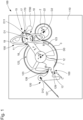
- This drive mechanism 100 comprises a structure 110, such as a plate, bridge or the like, on which is mounted an arm 1 pivoting around a main axis D0.
- This arm 1 carries a first mechanism, which comprises a satellite 10, which is pivotally mounted on the arm 1 around a first pivot axis D1, which is distant from the main axis D0.
- This satellite 10 comprises a first wheel 11, which is pivotally mounted around the first pivot axis D1 or a secondary pivot axis D11 which is parallel to it.
- the arm 1 is subjected to the restoring torque of a first energy source 12, such as a barrel, a weight system, or the like.
- a first energy source 12 such as a barrel, a weight system, or the like.
- the drive mechanism 100 further comprises at least a second energy source 22, which is arranged to subject a third mobile 3 which the drive mechanism 100 comprises to a restoring torque, directly or indirectly through a second mobile 2 mounted pivoting around a second pivot axis D2, as in the particular and non-limiting variant illustrated by the figures 1 And 2 .
- This second energy source 22 is the main energy source, and it is arranged to store more energy than the first energy source 12.
- the first wheel 11 is arranged to roll on the third mobile 3 in a regular forward rolling movement, under the action of the restoring torque of the first energy source 12.
- the satellite 10 thus constitutes a planetary mobile, which moves in rotation around the third mobile 3, around the main axis D0, always in the same direction, according to the arrow G (clockwise direction on the figure 1 ), and at constant speed.
- the third mobile 3 is arranged to remain in fixed position during a first elementary stroke of the satellite 10, and to perform a rotation, and in particular a rapid rotation, always in one direction, that of arrow B anti-clockwise on the figures 1 And 2 , during a second elementary stroke of the stroke of the satellite 10, under the action of the second energy source 22.
- the first wheel 11 drives the tourbillon cage 150 or carousel, or constitutes the tourbillon cage 150 or carousel.
- the arm 1 moves in the direction of the arrow E under the action of the first energy source 12 relative to the third mobile 3 when the latter is stopped, while that, when the third mobile 3 is recalled under the action of the second energy source 22, the arm 1, which is carried by the third mobile 3, moves retrogradely in the direction of the arrow F, relative to to the fixed structure 110, during the second elementary stroke of the satellite 10.
- the axis D1 Due to the successive rotations of the arm in the first direction of advance along the arrow E, and in the second reverse direction along the arrow F, the axis D1 performs a limited angular travel around the main axis D0.
- the first elementary stroke of the satellite 10 is much greater than the second elementary stroke of the stroke, in particular more than twenty times greater than the latter.
- the complete cycle lasts one minute, with fifty-eight seconds of slow speed travel of arm 1 in the first elementary stroke, and two seconds of rapid return of arm 1 in the first elementary stroke.
- the invention makes it possible to modulate the relationship between the first stroke part and the second elementary stroke in a different way; it is for example imaginable to obtain a first elementary stroke and a second elementary stroke that are equal.
- the drive mechanism 100 comprises stopping means 120, which are fixed on the structure 110, and which are more particularly arranged to cooperate with complementary stopping means 123 what does the third mobile 3 include for its maintenance in position, or that comprises another external mobile meshing directly or indirectly with the third mobile 3.
- the stopping means 120 comprise more particularly a trigger lever, which is arranged to cooperate successively with pins distributed on the third mobile 3, and which constitute these means of additional stop 123 in the non-limiting example illustrated by the figures 1 And 2 .
- these pins are arranged angularly in a regular manner. It is nevertheless possible to design other angular spacings to create specific displays.
- These stopping means 120 are disengageable, under the action of disengagement control means 13 which arm 1 comprises, when the first wheel 11 finishes its first elementary stroke, to authorize the pivoting of the third mobile 3 in a single direction ( arrow B anti-clockwise) under the action of the second energy source 22, causing a retrograde rotation of the arm 1 until the start of its angular travel.
- the third mobile 3 When the third mobile 3 is stopped in an angular stop position, the first wheel 11 performs a first elementary stroke, and the arm 1 moves in an angular advance stroke at a slow speed which is its display speed .
- the disengagement control means 13 disengage the stopping means 120, and the third mobile 3 is then free and subjected to the torque of the second energy source 22, directly or through the second mobile 2 depending on the construction variant chosen.
- the third mobile 3 then performs a rotation, and more particularly a sudden and almost instantaneous rotation, before returning to another angular stop position between another pin 123 and the trigger lever 120. And this rotation of the third mobile 3 causes the return retrograde arm 1 to its start position of angular travel, and in particular in the case illustrated at an accelerated speed which is much greater than its slow display speed.
- the first wheel 11 is arranged to roll inside the third mobile 3.
- Many other configurations are possible, in particular concerning the relative positions of the different pivot axes, with adapted cascades of returns.
- the operation of the drive mechanism 100 depends on the level of energy available at the second energy source 22.
- the second energy source is advantageously recharged by an automatic winding mechanism, not detailed here because it is well known to those skilled in the art: the first energy source 11 is permanently rearmed by the second energy source as long as the latter has sufficient energy, this first energy source 11 thus constitutes a buffer, and the driving of the satellite 10 by this first energy source 11 is thus a so-called constant force, or more precisely constant torque, mechanism.
- the stopping means 120 comprise a rocker, which forms a trigger lever, and which is pivotally mounted on a rocker axis D12, and which is returned in the direction of the arrow D by elastic return means 127, such as spring or similar.
- This rocker carries a rocker pin 129.
- the arm 1 comprises a ramp 13, which is arranged to cooperate with the rocker pin 129, at the end of the angular advance stroke of the arm 1, and to push the rocker in the direction of the arrow C, which makes it possible to eclipse a tip of the rocker comprising a support surface 128, which until then held in position a stop pin 123, which comprises the third mobile 3 (which comprises three at 120° in the present case).
- the third mobile 3 is then released, and can rotate, its previously immobilized pin 123 being able to pass under the arm 1.
- the position of the pins 123 directs the triggering, they guarantee the precision of the duration of a total stroke period.
- the arm 1 comprises limitation means 20, which tend to oppose the driving torque of the first energy source 12, and which are arranged to limit the rolling speed of the first wheel 11.
- limitation means 20 which tend to oppose the driving torque of the first energy source 12, and which are arranged to limit the rolling speed of the first wheel 11.
- these limitation means 20 are braking and/or friction and/or regulation means. They may in particular include aerodynamic braking means, by eddy current, or other. For example, the first 11th street may carry a seconds hand.
- the limiting means 20 are means for regulating the rolling speed of the first wheel 11 around the third mobile 3.
- the regulating mechanism is preferably at the level of the satellite 10 which constitutes a planetary mobile.
- the means for regulating the rolling speed of the first wheel 11 around the third mobile 3 comprise a stopper 17, such as an anchor or the like, and which is arranged to cooperate discontinuously with the first wheel 11, or with a synchronous mobile of the first wheel 11, or with a fourth mobile meshing directly or indirectly with the first wheel 11.
- the second pivot axis D2 is parallel to the main axis D0 and distinct from it.
- the third mobile 3 is arranged to pivot around the main axis D0.
- the satellite 10 constitutes all or part of the limitation means 20.
- the regulating member 15 comprises at least one inertial mass 1700 subjected to an alternating pivoting movement by an anchor 170, which the stopper 17 comprises, and which is arranged to cooperate with a ratchet 18 driven directly or indirectly by the first wheel 11.
- the ratchet 18 is coaxial with the first wheel 11.
- this ratchet 18 is an escape wheel.
- the first wheel 11 drives the cage of the tourbillon 150, or else constitutes the cage of the tourbillon 150.
- the axis of the resonator mechanism typically a sprung balance, that comprises the regulating member 15, coincides with the first pivot axis D1.
- the first wheel 11 drives the carousel cage or constitutes the carousel cage.
- the axis of the resonator mechanism typically a sprung balance, which the regulating member 15 comprises, is a secondary pivot axis, parallel to the first pivot axis D1, for example located at the distal end of a regulator 19 as illustrated on the figures 1 And 2 .
- the regulating member 15 comprises a regulator 19, which is driven directly or indirectly by the first wheel 1.
- this regulator 19 is synchronous with the first wheel 11, and is capable of constituting a first display of a first temporal quantity.
- the regulator 19 comprises a tourbillon or carousel cage.
- arm 1 constitutes or drives a display of a second temporal quantity.
- This arm can carry eccentric displays, for example on stars pivotally mounted on arm 1.
- the third mobile 3 constitutes or drives a display of a third temporal quantity, for example a minute display advancing in jumps.
- the second mobile 2 constitutes or drives a power reserve display.
- the invention also relates to a timepiece 1000 comprising at least one such timepiece movement 500, and which in a first variant is a watch.
- first energy source 12 and/or its second energy source 22 can conventionally comprise at least one barrel, and/or an electromechanical energy source, or other.
- the second energy source 22 is recharged by an automatic winding mechanism.
- the timepiece 1000 is static, and may in particular be a clock.
- first energy source 12 and/or its second energy source 22 can conventionally comprise at least one barrel, and/or an electromechanical energy source, or other.
- its first energy source 12 and/or its second energy source 22 comprises at least one weight, and this timepiece 1000 then comprises means for winding each weight.
- the first energy source 12 is a barrel making buffer, which makes it possible to only have to go back to the second energy source 22 which supplies the first energy source 12.
- the principle of the invention is applicable to many other variants, and to many particular applications.
- This principle is illustrated, in a simplified manner compared to the figures 1 And 2 , by the figures 4 to 9 , which only include the first energy source 12, illustrated in the form of a simple flat spring, the arm 1 carrying the first wheel 11, and the third mobile 3 on which this first wheel 11 turns.
- a tourbillon cage carried by the first wheel 11, performs one revolution per minute, the first wheel 11 moves on the third mobile 3 for approximately 18 seconds when the third mobile 3 is still in the fixed position, and continues to roll on this third mobile during the two seconds that lasts the 120° retrograde return of the third mobile 3 in the counterclockwise direction in these figures.
- FIG. 5 shows the whole in position just after such a retrograde return; there Figure 6 shows an intermediate position there Figure 7 shows the extreme angular position of arm 1 in clockwise travel, and the figure 8 illustrates the retrograde return in an anti-clockwise direction of the third mobile (visible by the change in position of marks 1, 2, 3) and of the arm 1 which it carries.
- FIG. 10 illustrates yet another variant, with an arm 1 acting as a cocking rake on a cocking barrel of the cage arm, constituting the first energy source 12, which drives the cage arm 1; under the effect of its torque, the tourbillon cage is driven and rotates on the circumference of the third mobile 3, the arm 1 moves according to the frequency and the gear ratio. Arm 1 leading the cage moves from its initial position of 0° and arrives at its maximum position of 120°.
- the second energy source 22 is unlocked, here constituted by the barrel of the basic movement of a watch.
- This barrel is in chain with a reduction mobile 223, and the latter in connection with the third mobile 3.
- the force of the barrel movement 22 will drive the reduction mobile 223 and in fact will lead the third mobile 3 into anti-rotation.
- a regulator with inverter comprising in particular a pinion, a ratchet 18, an anchor 170, is in series with the third mobile 3, and allows 'adjust the duration of the retrograde return, in particular between 1 and 10 seconds.
- the first energy source 12 here the spring of the cage arm
- the cage continues to operate by moving on the circumference of the third mobile 3.
- This variant of the Figure 10 allows the angular travel to be managed other than by the pins 123 of the variant of the figures 1 And 2 , which is replaced here by the position cog 221, it is here possible to manage other angular values, for example 360° to display a date passage, or other.
- the first energy source 12 here the spring of the cage arm, has a pre-winding giving the torque necessary for the operation of the tourbillon, this force will remain constant.
- Winding is done by the crown 220, the main barrel 22 will no longer intercede with the finishing train as in the usual technique.
- This arrangement also allows the moon to be corrected directly through the crown; it is no longer necessary to integrate a corrector integrated into the caseband.
- the invention ensures an almost constant driving force to the regulating mechanism, in particular a tourbillon or carousel cage, throughout the power reserve of the main barrel.
- THE figures 11 to 14 illustrate the wide latitude offered by the invention for the positioning of the different displays.
- the hours and minutes are read on a dial at 12 o'clock, that of the power reserve on a sector with a retrograde hand at 9 o'clock, that of the moon and/or day/night display, or even sunset, or other, at 3 o'clock, while the tourbillon has a movement of 120°, and it is possible to direct the movement of the cage over 120° according to a substantially peripheral movement as on the figures 11 and 14 , or according to a movement around an axis eccentric as much as possible as on the figures 12 and 13 , with a retrograde movement of the cage respectively from left to right, or from right to left.
- the value of 120° taken for the examples is in no way binding, the angular value depends on the desired duration of hourly travel, the value of the retrograde travel is also adjustable, for example between 2 and 5 seconds, and allows you to obtain a non-abrupt retrograde return, devoid of shock.
- the retrograde return of the cage powers the passage of the minutes.
- the retrograde return is not linked to the frequency of the resonator mechanism, and has no influence on the course of the movement.
Description
L'invention concerne un mouvement d'horlogerie comportant au moins un mécanisme résonateur qui est un tourbillon ou un carrousel, et comportant un mécanisme d'entraînement d'horlogerie, comportant une structure sur laquelle est monté pivotant, autour d'un axe principal, un bras porteur d'un premier mécanisme, lequel est monté pivotant sur ledit bras autour d'un premier axe de pivotement distant dudit axe principal et comporte une première roue montée pivotante autour dudit premier axe de pivotement ou d'un axe de pivotement qui lui est parallèle, ledit bras étant soumis au couple de rappel d'une première source d'énergie, ledit mécanisme d'entraînement comportant encore au moins une deuxième source d'énergie agencée pour soumettre à un couple de rappel un troisième mobile que comporte ledit mécanisme d'entraînement, directement ou indirectement au travers d'un deuxième mobile monté pivotant autour d'un deuxième axe de pivotement.The invention relates to a watch movement comprising at least one resonator mechanism which is a tourbillon or a carousel, and comprising a watch drive mechanism, comprising a structure on which is pivotally mounted, around a main axis, an arm carrying a first mechanism, which is pivotally mounted on said arm around a first pivot axis distant from said main axis and comprises a first wheel pivotally mounted around said first pivot axis or a pivot axis which is parallel, said arm being subjected to the restoring torque of a first energy source, said drive mechanism further comprising at least a second energy source arranged to subject a third mobile which said mechanism comprises to a restoring torque drive, directly or indirectly through a second mobile mounted pivoting around a second pivot axis.
L'invention concerne le domaine des mécanismes d'entraînement d'horlogerie, et le domaine des mécanismes d'affichage d'horlogerie.The invention relates to the field of clockwork drive mechanisms, and the field of clockwork display mechanisms.
Les amateurs de complications horlogères sont sensibles à une certaine animation des affichages d'une pièce d'horlogerie, ce que peuvent procurer des mécanismes d'affichage rétrograde, ou encore des mécanismes de tourbillon ou similaire, qui de surcroît garantissent une meilleure insensibilité aux positions.Lovers of watch complications are sensitive to a certain animation of the displays of a timepiece, which can be provided by retrograde display mechanisms, or even tourbillon mechanisms or similar, which also guarantee better insensitivity to positions .
Un éclatement des affichages est également apprécié, et permet d'offrir une nouvelle physionomie du cadran ou du mécanisme.A breakdown of the displays is also appreciated, and makes it possible to offer a new look to the dial or mechanism.
Les affichages rétrogrades sont généralement limités à l'entraînement d'aiguilles, ou plus rarement de disques.Retrograde displays are generally limited to driving needles, or more rarely discs.
L'entraînement rétrograde d'une cage de tourbillon ou de carrousel n'a jamais pu être réalisé, car une cage ne peut revenir en arrière sur sa roue fixe, et doit tourner toujours dans le même sens. Si l'on introduit un système de débrayage, par came ou similaire, pour ramener la cage en arrière, la marche cesse durant le mouvement rétrograde, ce qui n'est pas admissible.The retrograde drive of a tourbillon or carousel cage has never been possible, because a cage cannot return backwards on its fixed wheel, and must always rotate in the same direction. If we introduce a declutching system, by cam or similar, to bring the cage backwards, walking stops during the retrograde movement, which is not admissible.
Le document
L'invention se propose de développer un mécanisme d'entraînement rétrograde qui soit capable d'embarquer des mobiles d'inertie beaucoup plus importante que des aiguilles, notamment des tourbillons ou similaires, et de ce fait de proposer des affichages entièrement nouveaux.The invention aims to develop a retrograde drive mechanism which is capable of carrying mobiles with much greater inertia than hands, in particular tourbillons or the like, and therefore to offer entirely new displays.
A cet effet, l'invention concerne un mouvement d'horlogerie selon la revendication 1.To this end, the invention relates to a timepiece movement according to
L'invention concerne encore une pièce d'horlogerie comportant au moins un tel mécanisme d'entraînement.The invention also relates to a timepiece comprising at least one such drive mechanism.
D'autres caractéristiques et avantages de l'invention apparaîtront à la lecture de la description détaillée qui va suivre, en référence aux dessins annexés, où :
- la
figure 1 représente, de façon schématisée, partielle, et en vue en plan, un mouvement d'horlogerie selon l'invention ; - la
figure 2 représente, de façon schématisée, et en perspective éclatée, le mouvement de lafigure 1 , - la
figure 3 est un schéma-blocs représentant une pièce d'horlogerie comportant un tel mouvement ; - les
figures 4 à 9 illustrent, de façon partielle, une autre variante, fonctionnant sur une course angulaire de 120° du bras, tel que visible sur lafigure 4 en vue en plan, comme lesfigures 5 à 8 qui illustrent les positions des mobiles à différents instants, lafigure 9 étant une vue de côté de ce mécanisme ; - la
figure 10 représente, de façon schématisée, et en vue en plan, une autre variante encore de mécanisme selon l'invention ; - les
figures 11 à 14 illustrent, en vue en plan, différentes implantations sur une montre d'un mécanisme selon l'invention.
- there
figure 1 represents, schematically, partially, and in plan view, a clock movement according to the invention; - there
figure 2 represents, schematically, and in exploded perspective, the movement of thefigure 1 , - there
Figure 3 is a block diagram representing a timepiece comprising such a movement; - THE
figures 4 to 9 illustrate, partially, another variant, operating on an angular travel of 120° of the arm, as visible on theFigure 4 in plan view, like thefigures 5 to 8 which illustrate the positions of the mobiles at different times, theFigure 9 being a side view of this mechanism; - there
Figure 10 represents, schematically, and in plan view, yet another variant of the mechanism according to the invention; - THE
figures 11 to 14 illustrate, in plan view, different installations on a watch of a mechanism according to the invention.
L'invention concerne un mouvement d'horlogerie 500 comportant au moins un organe régulateur 15 qui est un tourbillon 150 ou un carrousel, et comportant un mécanisme d'entraînement 100 d'horlogerie, qui présente l'intérêt de pouvoir être utilisé dans une montre, ou encore dans une pièce d'horlogerie statique, avec des fonctionnalités nouvelles.The invention relates to a
Ce mécanisme d'entraînement 100 comporte une structure 110, telle que platine, pont ou similaire, sur laquelle est monté un bras 1 pivotant autour d'un axe principal D0. Ce bras 1 est porteur d'un premier mécanisme, qui comporte un satellite 10, lequel est monté pivotant sur le bras 1 autour d'un premier axe de pivotement D1, qui est distant de l'axe principal D0. Ce satellite 10 comporte une première roue 11, qui est montée pivotante autour du premier axe de pivotement D1 ou d'un axe de pivotement secondaire D11 qui lui est parallèle.This
Le bras 1 est soumis au couple de rappel d'une première source d'énergie 12, telle qu'un barillet, un système de poids, ou autre.The
Le mécanisme d'entraînement 100 comporte encore au moins une deuxième source d'énergie 22, qui est agencée pour soumettre à un couple de rappel un troisième mobile 3 que comporte le mécanisme d'entraînement 100, directement ou indirectement au travers d'un deuxième mobile 2 monté pivotant autour d'un deuxième axe de pivotement D2, comme dans la variante particulière et non limitative illustrée par les
Cette deuxième source d'énergie 22 est la source d'énergie principale, et elle est agencée pour stocker davantage d'énergie que la première source d'énergie 12.This
La première roue 11 est agencée pour rouler sur le troisième mobile 3 dans un mouvement de roulement d'avance régulier, sous l'action du couple de rappel de la première source d'énergie 12.The
Le satellite 10 constitue, ainsi, un mobile planétaire, qui se déplace en rotation autour du troisième mobile 3, autour de l'axe principal D0, toujours dans le même sens, selon la flèche G (sens horaire sur la
De façon propre à l'invention, le troisième mobile 3 est agencé pour rester en position fixe pendant une première course élémentaire du satellite 10, et pour effectuer une rotation, et de façon particulière une rotation rapide, toujours dans un seul sens, celui de la flèche B anti-horaire sur les
Et la première roue 11 entraîne la cage du tourbillon 150 ou carrousel, ou constitue la cage du tourbillon 150 ou carrousel.And the
Ainsi, par rapport à la structure fixe 110, le bras 1 se déplace dans le sens de la flèche E sous l'action de la première source d'énergie 12 relativement au troisième mobile 3 quand celui-ci est à l'arrêt, tandis que, lors du rappel du troisième mobile 3 sous l'action de la deuxième source d'énergie 22, le bras 1, qui est porté par le troisième mobile 3, se déplace de façon rétrograde dans le sens de la flèche F, par rapport à la structure fixe 110, pendant la deuxième course élémentaire du satellite 10.Thus, relative to the
On comprend que le satellite 10 roule en permanence autour du troisième mobile 3, et qu'il continue à tourner par rapport au troisième mobile 3 pendant la rotation de ce dernier. Il y a donc une alternance de premières courses élémentaires et de deuxièmes courses élémentaires.We understand that the
Du fait des rotations successives du bras dans le premier sens d'avance selon la flèche E, et selon le deuxième sens réverse selon la flèche F, l'axe D1 effectue une course angulaire limitée autour de l'axe principal D0.Due to the successive rotations of the arm in the first direction of advance along the arrow E, and in the second reverse direction along the arrow F, the axis D1 performs a limited angular travel around the main axis D0.
De façon particulière et non limitative, la première course élémentaire du satellite 10, est très supérieure à la deuxième course élémentaire de la course, notamment plus de vingt fois supérieure à celle-ci.In a particular and non-limiting manner, the first elementary stroke of the
Dans l'exemple avantageux illustré par les
L'invention permet toutefois de moduler autrement le rapport entre la première partie de course et la deuxième course élémentaire de course, il est par exemple imaginable d'obtenir une première course élémentaire et une deuxième course élémentaire égales.However, the invention makes it possible to modulate the relationship between the first stroke part and the second elementary stroke in a different way; it is for example imaginable to obtain a first elementary stroke and a second elementary stroke that are equal.
Dans la variante illustrée par les
Ces moyens d'arrêt 120 sont débrayables, sous l'action de moyens de commande de débrayage 13 que comporte le bras 1, quand la première roue 11 termine sa première course élémentaire, pour autoriser le pivotement du troisième mobile 3 dans un sens unique (flèche B anti-horaire) sous l'action de la deuxième source d'énergie 22 en entraînant une rotation rétrograde du bras 1 jusqu'au début de sa course angulaire.These stopping means 120 are disengageable, under the action of disengagement control means 13 which
Quand le troisième mobile 3 est à l'arrêt dans une position angulaire de butée, la première roue 11 effectue une première course élémentaire, et le bras 1 se déplace en course angulaire d'avance à une vitesse lente qui est sa vitesse d'affichage. A la fin de cette première course élémentaire de la première roue 11, les moyens de commande de débrayage 13 débrayent les moyens d'arrêt 120, et le troisième mobile 3 est alors libre et soumis au couple de la deuxième source d'énergie 22, directement ou au travers du deuxième mobile 2 selon la variante de construction retenue. Le troisième mobile 3 effectue alors une rotation, et plus particulièrement une rotation brusque et quasiment instantanée, avant de revenir à une autre position angulaire de butée entre une autre goupille 123 et le levier déclencheur 120. Et cette rotation du troisième mobile 3 entraîne le retour rétrograde du bras 1 à sa position de début de course angulaire, et notamment dans le cas illustré à une vitesse accélérée qui est très supérieure à sa vitesse lente d'affichage.When the
Dans une autre variante, la première roue 11 est agencée pour rouler à l'intérieur du troisième mobile 3. Bien d'autres configurations sont envisageables, notamment concernant les positions relatives des différents axes de pivotement, avec des cascades de renvois adaptées.In another variant, the
Naturellement il est encore possible de soumettre le troisième mobile 3 au couple d'au moins une troisième source d'énergie, par exemple en engrènement direct.Naturally it is still possible to subject the third mobile 3 to the torque of at least a third energy source, for example in direct meshing.
Le fonctionnement du mécanisme d'entraînement 100 est tributaire du niveau d'énergie disponible au niveau de la deuxième source d'énergie 22. Dans le cas où le mécanisme d'entraînement 100 est intégré dans une montre, la deuxième source d'énergie est avantageusement rechargée par un mécanisme de remontage automatique, non détaillé ici car bien connue de l'homme du métier : la première source d'énergie 11 est en permanence réarmée par la deuxième source d'énergie tant que celle-ci dispose de suffisamment d'énergie, cette première source d'énergie 11 constitue ainsi un tampon, et l'entraînement du satellite 10 par cette première source d'énergie 11 est ainsi un mécanisme dit à force constante, ou plus précisément à couple constant.The operation of the
Dans la variante très compacte illustrée par les
Le bras 1 comporte une rampe 13, qui est agencée pour coopérer avec la goupille de bascule 129, en fin de course angulaire d'avance du bras 1, et pour repousser la bascule dans le sens de la flèche C, ce qui permet d'éclipser un bec de la bascule comportant une surface d'appui 128, qui jusque-là maintenait en position une goupille de butée 123, que comporte le troisième mobile 3 (qui en comporte trois à 120° dans le cas d'espèce). Le troisième mobile 3 est alors libéré, et peut tourner, sa goupille 123 précédemment immobilisée pouvant passer sous le bras 1. La position des goupilles 123 dirige le déclenchement, elles sont garantes de la précision de la durée d'une période de course totale.The
De façon avantageuse, le bras 1 comporte des moyens de limitation 20, qui tendent à s'opposer au couple moteur de la première source d'énergie 12, et qui sont agencés pour limiter la vitesse de roulement de la première roue 11. En effet, tout ce qui peut ralentir le système est avantageux, pour un fonctionnement régulier du mécanisme à force constante que constitue l'invention.Advantageously, the
Plus particulièrement, ces moyens de limitation 20 sont des moyens de freinage et/ou de friction et/ou de régulation. Ils peuvent notamment comporter des moyens de freinage aérodynamique, par courants de Foucault, ou autre. Par exemple, la première rue 11 peut porter une aiguille des secondes.More particularly, these limitation means 20 are braking and/or friction and/or regulation means. They may in particular include aerodynamic braking means, by eddy current, or other. For example, the first 11th street may carry a seconds hand.
Plus particulièrement encore, comme dans le cas non limitatif illustré par les
Tel que visible dans une variante non limitative illustrée par les
De façon particulière et tel que visible sur les
De façon particulière et tel que visible sur les
Tout particulièrement, le satellite 10 constitue tout ou partie des moyens de limitation 20.In particular, the
Plus particulièrement, l'organe régulateur 15 comporte au moins une masse inertielle 1700 soumise à un mouvement de pivotement alternatif par une ancre 170, que comporte l'arrêtoir 17, et qui est agencée pour coopérer avec un rochet 18 entraîné directement ou indirectement par la première roue 11.More particularly, the regulating
Plus particulièrement, le rochet 18 est coaxial à la première roue 11.More particularly, the
Plus particulièrement ce rochet 18 est une roue d'échappement.More particularly this
Quand l'organe régulateur 15.est un tourbillon 150, la première roue 11 entraîne la cage du tourbillon 150, ou bien constitue la cage du tourbillon 150. Dans ce cas, l'axe du mécanisme résonateur, typiquement un balancier-spiral, que comporte l'organe régulateur 15, est confondu avec le premier axe de pivotement D1.When the regulating
Quand l'organe régulateur 15 est un carrousel, la première roue 11 entraîne la cage du carrousel ou constitue la cage du carrousel. Dans ce cas, l'axe du mécanisme résonateur, typiquement un balancier-spiral, que comporte l'organe régulateur 15, est un axe de pivotement secondaire, parallèle au premier axe de pivotement D1, par exemple situé à l'extrémité distale d'un régulateur 19 tel qu'illustré sur les
Plus particulièrement, l'organe régulateur 15 comporte un régulateur 19, qui est entraîné directement ou indirectement par la première roue 1.More particularly, the regulating
Plus particulièrement, ce régulateur 19 est synchrone avec la première roue 11, et est apte à constituer un premier afficheur d'une première grandeur temporelle.More particularly, this
Plus particulièrement encore, le régulateur 19 comporte une cage de tourbillon ou de carrousel.Even more particularly, the
Chaque mobile du mécanisme d'entraînement du mouvement selon l'invention est utilisable pour un affichage particulier. Ainsi, plus particulièrement, le bras 1 constitue ou entraîne un afficheur d'une deuxième grandeur temporelle. Ce bras peut porter des affichages excentrés, par exemple sur des étoiles montées pivotantes sur le bras 1.Each mobile of the movement drive mechanism according to the invention can be used for a particular display. Thus, more particularly,
De façon similaire, plus particulièrement, le troisième mobile 3 constitue ou entraîne un afficheur d'une troisième grandeur temporelle, par exemple un afficheur des minutes avançant par sauts.Similarly, more particularly, the third mobile 3 constitutes or drives a display of a third temporal quantity, for example a minute display advancing in jumps.
Plus particulièrement, le deuxième mobile 2 constitue ou entraîne un afficheur de réserve de marche.More particularly, the second mobile 2 constitutes or drives a power reserve display.
On comprend que ce mécanisme d'entraînement propre à l'invention autorise un affichage très vivant de l'écoulement du temps, par le roulement très visible de la première roue 11 sur le troisième mobile 3, et par le retour rétrograde périodique du bras 1. Chaque mobile est utilisable pour porter un affichage décentré.We understand that this drive mechanism specific to the invention allows a very vivid display of the passage of time, by the very visible rolling of the
L'invention concerne encore une pièce d'horlogerie 1000 comportant au moins un tel mouvement d'horlogerie 500, et qui dans une première variante est une montre. Sa première source d'énergie 12 et/ou sa deuxième source d'énergie 22 peut classiquement comporter au moins un barillet, et/ou une source d'énergie électromécanique, ou autre. Avantageusement la deuxième source d'énergie 22 est rechargée par un mécanisme de remontage automatique.The invention also relates to a
Dans une autre variante, la pièce d'horlogerie 1000 est statique, et peut être notamment une pendule. Sa première source d'énergie 12 et/ou sa deuxième source d'énergie 22 peut classiquement comporter au moins un barillet, et/ou une source d'énergie électromécanique, ou autre. Ou encore sa première source d'énergie 12 et/ou sa deuxième source d'énergie 22 comporte au moins un poids, et cette pièce d'horlogerie 1000 comporte alors des moyens de remontage de chaque poids. Toutefois de préférence la première source d'énergie 12 est un barillet faisant tampon, ce qui permet de ne devoir remonter que la deuxième source d'énergie 22 qui alimente la première source d'énergie 12.In another variant, the
Le principe de l'invention est applicable à bien d'autres variantes, et à de nombreuses applications particulières. Ce principe est illustré, de façon simplifiée par rapport aux
La
On remarque que le ressort de barillet de mouvement de base n'intercède plus avec le rouage de finissage comme sur un mouvement classique. Il a maintenant pour fonction unique de donner l'impulsion nécessaire au positionnement du troisième mobile 3.We notice that the base movement barrel spring no longer intercedes with the finishing train as on a classic movement. It now has the sole function of providing the impulse necessary for positioning the third mobile 3.
La première source d'énergie 12, ici le ressort du bras de cage, a un pré-armage donnant le couple nécessaire au fonctionnement du tourbillon, cette force restera constante. La course angulaire de 120° en rotation anti-horaire du troisième mobile 3 arme de manière régulière le ressort de bras de cage.The
De cette façon, il est concevable d'élaborer plusieurs types de déplacement de l'aiguille d'heure et des minutes, ainsi que des complications comme les indications de la lune, et/ou jour/nuit, et/ou de la réserve de marche, tel que visible sur les
Le remontage se fait par la couronne 220, le barillet principal 22 n'intercèdera plus avec le rouage de finissage comme dans la technique usuelle.Winding is done by the
Cet agencement permet, encore, de faire la correction de la lune directement par la couronne, il n'est plus nécessaire d'intégrer un correcteur intégré à la carrure.This arrangement also allows the moon to be corrected directly through the crown; it is no longer necessary to integrate a corrector integrated into the caseband.
On comprend que l'invention assure une force motrice quasi constante au mécanisme régulateur, notamment une cage de tourbillon ou de carrousel, durant toute la réserve de marche du barillet principal.We understand that the invention ensures an almost constant driving force to the regulating mechanism, in particular a tourbillon or carousel cage, throughout the power reserve of the main barrel.
Les
La valeur de 120° prise pour les exemples n'est nullement contraignante, la valeur angulaire dépend de la durée de course horaire désirée, la valeur de la course rétrograde est elle aussi ajustable, par exemple entre 2 et 5 secondes, et permet d'obtenir un retour rétrograde non brusque, dépourvu de choc.The value of 120° taken for the examples is in no way binding, the angular value depends on the desired duration of hourly travel, the value of the retrograde travel is also adjustable, for example between 2 and 5 seconds, and allows you to obtain a non-abrupt retrograde return, devoid of shock.
Le retour rétrograde de la cage permet d'alimenter le passage des minutes.The retrograde return of the cage powers the passage of the minutes.
Le retour rétrograde n'est pas lié à la fréquence du mécanisme résonateur, et n'a aucune influence sur la marche du mouvement.The retrograde return is not linked to the frequency of the resonator mechanism, and has no influence on the course of the movement.
Dans d'autres variantes d'exécution il est possible d'équiper le troisième mobile de plusieurs satellites 10 sur sa périphérie. Il est aussi possible de concevoir un système sur plusieurs étages pour gérer des fonctions distinctes.In other execution variants it is possible to equip the third mobile with
Claims (19)
- Timepiece movement (500) including at least one regulating member (15) which is a tourbillon (150) or karussel, and including a mechanism (100) for driving the cage of the tourbillon or karussel, which mechanism includes a fixed structure (110) on which is pivotally mounted, about a main axis (D0), an arm (1) carrying a planetary gear (10) included in said drive mechanism, said planetary gear (10), which forms a first wheel set, is pivotally mounted on said arm (1) about a first pivot axis (D1) remote from said main axis (D0) and includes a first wheel (11) which is arranged to drive the cage of the tourbillon (150) or karussel or to form the cage of said tourbillon (150) or karussel, said first wheel (11) being pivotally mounted about said first pivot axis (D1) or a secondary pivot axis (D11) that is parallel thereto, said arm (1) being subjected to the restoring torque of a first energy source (12), said drive mechanism (100) further including at least a second energy source (22) arranged to subject to a restoring torque a third wheel set (3) included in said drive mechanism (100), directly, or indirectly via a second wheel set (2) pivotally mounted about a second pivot axis (D2), said first wheel (11) being arranged to roll, under the action of said first energy source (12), over said third wheel set (3) in a regular forward rolling motion with respect to the fixed structure (110) in a single direction of rotation, said third wheel set (3) being arranged to remain in a fixed position during a first basic travel of said planetary gear (10), said first wheel (11) being also arranged, under the action of said second energy source (22), to make a rotation in a single direction during a second basic travel of the travel of said planetary gear (10), characterised in that during said second basic travel said arm (1), which is carried by said third wheel set (3), moves backwards with respect to said fixed structure (110).
- Timepiece movement (500) according to claim 1, characterised in that said drive mechanism (100) includes stop means (120) arranged to cooperate with complementary stop means (123) included in said third wheel set (3) to hold it in position, or comprised in another external wheel set meshing directly or indirectly with said third wheel set (3), said stop means (120) being able to be uncoupled, under the action of uncoupling control means (13) included in said arm (1), when the planetary gear (10) completes its first basic travel, to allow pivoting of said third wheel set (3) in a single direction under the action of said second energy source (22) causing a backward rotation of said arm (1) to the start of its said angular travel.
- Timepiece movement (500) according to claim 1 or 2, characterised in that said arm (1) includes banking means (20) tending to resist the drive torque of said first energy source (12), and arranged to limit the rolling speed of said first wheel (11).
- Timepiece movement (500) according to claim 3, characterised in that said banking means (20) are braking means and/or friction means and/or regulating means.
- Timepiece movement (500) according to claim 4, characterised in that said banking means (20) are means for regulating the rolling speed of said first wheel (11) about said third wheel set (3).
- Timepiece movement (500) according to claim 5, characterised in that said means regulating the rolling speed of said first wheel (11) about said third wheel set (3) include a stop device (17) arranged to cooperate in a discontinuous manner with said first wheel (11) or with a fourth wheel set meshing directly or indirectly with said first wheel (11).
- Timepiece movement (500) according to one of claims 1 to 6, characterised in that said second pivot axis (D2) is parallel to said main axis (D0) and distinct therefrom.
- Timepiece movement (500) according to one of claims 1 to 7, characterised in that said third wheel set (3) is arranged to pivot about said main axis (D0).
- Timepiece movement (500) according to claim 3 and one of claims 1 to 8, characterised in that said planetary gear (10) forms all or part of said banking means (20).
- Timepiece movement (500) according to claim 9, characterised in that said regulating member (15) includes a resonator mechanism with at least one inertia mass (1700) subjected to a pivoting alternating motion by a pallet (170) cooperating with a ratchet (18) driven directly or indirectly by said first wheel (11).
- Timepiece movement (500) according to claim 10, characterised in that said ratchet (18) is coaxial to said first wheel (11).
- Timepiece movement (500) according to one of claims 9 to 11, characterised in that said regulating member (15) includes a governor (19) driven directly or indirectly by said first wheel (11).
- Timepiece movement (500) according to claim 12, characterised in that said governor (19) is synchronous with said first wheel (11) and forms a first display of a first time magnitude.
- Timepiece movement (500) according to claim 12 or 13, characterised in that said governor (19) includes a tourbillon or karussel cage.
- Timepiece movement (500) according to one of claims 1 to 14, characterised in that said arm (1) forms or drives a display of a second time magnitude.
- Timepiece movement (500) according to one of claims 1 to 15, characterised in that said third wheel set (3) forms or drives a display of a third time magnitude.
- Timepiece movement (500) according to one of claims 1 to 16, characterised in that said second wheel set (2) forms or drives a power reserve display.
- Timepiece (1000) including at least one timepiece movement (500) according to one of claims 1 to 17.
- Timepiece (1000) according to claim 18, characterised in that said timepiece is a watch, and in that said first energy source (12) and/or said second energy source (22) is a barrel.
Priority Applications (10)
| Application Number | Priority Date | Filing Date | Title |
|---|---|---|---|
| EP18185167.6A EP3599516B1 (en) | 2018-07-24 | 2018-07-24 | Timepiece retrograde tourbillon or karussel |
| JP2019114359A JP6796686B2 (en) | 2018-07-24 | 2019-06-20 | Retrograde tourbillon or carousel for timekeeping |
| US16/517,029 US11360432B2 (en) | 2018-07-24 | 2019-07-19 | Retrograde tourbillon or karussel for timepieces |
| EP19187588.9A EP3599517B1 (en) | 2018-07-24 | 2019-07-22 | Timepiece retrograde tourbillon or karussel |
| RU2019123139A RU2712959C1 (en) | 2018-07-24 | 2019-07-23 | Retrograde tourbillon or carousel for clock |
| CN201910671796.6A CN110780573B (en) | 2018-07-24 | 2019-07-24 | Timepiece movement and timepiece |
| US16/912,183 US11493884B2 (en) | 2018-07-24 | 2020-06-25 | Timepiece retrograde tourbillon or karussel |
| JP2020121197A JP7063949B2 (en) | 2018-07-24 | 2020-07-15 | Timekeeper retrograde tool Biron or carousel |
| RU2020123925A RU2742378C1 (en) | 2018-07-24 | 2020-07-20 | Hourly retrograde tourbillon or carousel |
| CN202010710207.3A CN112286031B (en) | 2018-07-24 | 2020-07-22 | Timepiece movement and timepiece comprising a timepiece movement |
Applications Claiming Priority (1)
| Application Number | Priority Date | Filing Date | Title |
|---|---|---|---|
| EP18185167.6A EP3599516B1 (en) | 2018-07-24 | 2018-07-24 | Timepiece retrograde tourbillon or karussel |
Publications (2)
| Publication Number | Publication Date |
|---|---|
| EP3599516A1 EP3599516A1 (en) | 2020-01-29 |
| EP3599516B1 true EP3599516B1 (en) | 2024-04-03 |
Family
ID=63041868
Family Applications (1)
| Application Number | Title | Priority Date | Filing Date |
|---|---|---|---|
| EP18185167.6A Active EP3599516B1 (en) | 2018-07-24 | 2018-07-24 | Timepiece retrograde tourbillon or karussel |
Country Status (5)
| Country | Link |
|---|---|
| US (1) | US11360432B2 (en) |
| EP (1) | EP3599516B1 (en) |
| JP (1) | JP6796686B2 (en) |
| CN (1) | CN110780573B (en) |
| RU (1) | RU2712959C1 (en) |
Families Citing this family (2)
| Publication number | Priority date | Publication date | Assignee | Title |
|---|---|---|---|---|
| EP3599517B1 (en) * | 2018-07-24 | 2021-03-10 | Harry Winston SA | Timepiece retrograde tourbillon or karussel |
| JP7347103B2 (en) * | 2019-10-16 | 2023-09-20 | セイコーエプソン株式会社 | clock |
Family Cites Families (19)
| Publication number | Priority date | Publication date | Assignee | Title |
|---|---|---|---|---|
| SU1118956A1 (en) * | 1982-02-01 | 1984-10-15 | Пензенский Политехнический Институт | Wrist watch winding mechanism |
| DE602005013758D1 (en) * | 2004-04-15 | 2009-05-20 | Montres Breguet Sa Manufacture | CLOCK WITH AT LEAST TWO TOURBILLONS |
| JP4737634B2 (en) * | 2006-08-30 | 2011-08-03 | セイコーインスツル株式会社 | Mechanical watch with rotating cage |
| CH701725B1 (en) * | 2006-09-25 | 2011-03-15 | Franck Mueller Watchland S A | Tourbillon timepiece. |
| RU2456658C2 (en) * | 2008-03-11 | 2012-07-20 | Пармиджани Флерье С.А. | Coaxial clock mechanism |
| DE602008003534D1 (en) * | 2008-04-30 | 2010-12-30 | Cartier Creation Studio Sa | Mechanism for preventing gear variations due to the action of gravity on a regulating device with balance spring and clock equipped with this mechanism |
| CN101458494B (en) | 2009-01-09 | 2011-06-08 | 天津海鸥表业集团有限公司 | Mechanical wrist watch with double escapement mechanism |
| CH700222B1 (en) * | 2009-01-15 | 2015-04-15 | Temps Sa Fab Du | automatic watch movement escapement mounted on the oscillating weight. |
| CN201402375Y (en) | 2009-03-26 | 2010-02-10 | 天津海鸥表业集团有限公司 | Mechanical watch with two tourbillons |
| CH705244B1 (en) * | 2011-07-07 | 2016-06-30 | Gfpi S A | Timepiece. |
| RU113594U1 (en) * | 2011-08-10 | 2012-02-20 | Общество с ограниченной ответственностью "Константин Чайкин" | MECHANISM OF NON-STOP OPERATION OF HOURS IN SHABBAT AND CLOCK WITH MECHANISM OF NON-STOP OPERATION OF HOURS IN SHABBAT |
| EP2793087B1 (en) * | 2013-04-18 | 2016-06-01 | Glashütter Uhrenbetrieb GmbH | Tourbillon |
| CH708658A1 (en) * | 2013-10-03 | 2015-04-15 | Gfpi S A | Clockwork movement comprising a differential gear between regulating members. |
| JP6256949B2 (en) | 2014-03-11 | 2018-01-10 | セイコーインスツル株式会社 | Special display mechanism, movement and watch |
| EP2950164A1 (en) * | 2014-05-28 | 2015-12-02 | Omega SA | System for optional quick correction of time information |
| CH712129B1 (en) | 2016-02-04 | 2019-12-30 | Red & White Intellectual Property Man Sa | Timepiece with a tourbillon mechanism. |
| CH712973B1 (en) * | 2016-09-23 | 2023-12-29 | Bucherer Ag | Tourbillon and watch with tourbillon. |
| CN206450978U (en) | 2016-12-20 | 2017-08-29 | 天津海鸥表业集团有限公司 | Hand setting mechanism of tourbillon watch |
| EP3599517B1 (en) * | 2018-07-24 | 2021-03-10 | Harry Winston SA | Timepiece retrograde tourbillon or karussel |
-
2018
- 2018-07-24 EP EP18185167.6A patent/EP3599516B1/en active Active
-
2019
- 2019-06-20 JP JP2019114359A patent/JP6796686B2/en active Active
- 2019-07-19 US US16/517,029 patent/US11360432B2/en active Active
- 2019-07-23 RU RU2019123139A patent/RU2712959C1/en active
- 2019-07-24 CN CN201910671796.6A patent/CN110780573B/en active Active
Also Published As
| Publication number | Publication date |
|---|---|
| CN110780573A (en) | 2020-02-11 |
| CN110780573B (en) | 2021-06-22 |
| JP2020016641A (en) | 2020-01-30 |
| US11360432B2 (en) | 2022-06-14 |
| RU2712959C1 (en) | 2020-02-03 |
| EP3599516A1 (en) | 2020-01-29 |
| US20200033807A1 (en) | 2020-01-30 |
| JP6796686B2 (en) | 2020-12-09 |
Similar Documents
| Publication | Publication Date | Title |
|---|---|---|
| EP2453322B1 (en) | Fast time quantity indicator corrector for a timepiece | |
| EP3612896B1 (en) | Locking device for a timepiece mechanism | |
| WO2005006087A1 (en) | Display device for a watch | |
| EP3764168B1 (en) | Timepiece display mechanism with elastic hand | |
| EP3193216B1 (en) | Timepiece mechanism with a tourbillon | |
| EP3059643A1 (en) | Chronograph mechanism | |
| EP3599516B1 (en) | Timepiece retrograde tourbillon or karussel | |
| EP3435176B1 (en) | Torque smoothing for timepiece with chiming mechanism, in particular with chiming mechanism | |
| EP3059642B1 (en) | Chronograph mechanism | |
| EP3584643A1 (en) | Instantaneous command device for date display of timepieces | |
| EP3382468B1 (en) | Movement with extension of running reserve | |
| EP3945374A1 (en) | Sympathique timepiece assembly | |
| EP3599517B1 (en) | Timepiece retrograde tourbillon or karussel | |
| EP3599515B1 (en) | Timepiece driving mechanism | |
| CH715195B1 (en) | Clockwork drive mechanism. | |
| CH715196B1 (en) | Clockwork movement comprising an arm carrying a satellite which comprises a tourbillon or carousel. | |
| EP3832397A1 (en) | Stepwise timepiece display mechanism | |
| CH715222A2 (en) | Clock movement comprising a retrograde arm carrying a tourbillon cage or carousel. | |
| CH712601A1 (en) | Clockwork movement comprising a regulating member mounted in a pivotable mobile support. | |
| EP4113215A1 (en) | Movement for a timepiece and timepiece comprising such a movement | |
| EP4254079A1 (en) | Mechanism for displaying the phases of the moon for a timepiece | |
| CH716894A2 (en) | Instant-jump clock display mechanism. | |
| EP2254007B1 (en) | Device for displaying the power reserve for a timepiece | |
| EP4189493A1 (en) | Sympathetic timekeeping assembly | |
| EP4189495A1 (en) | Sympathetic timekeeping assembly |
Legal Events
| Date | Code | Title | Description |
|---|---|---|---|
| PUAI | Public reference made under article 153(3) epc to a published international application that has entered the european phase |
Free format text: ORIGINAL CODE: 0009012 |
|
| STAA | Information on the status of an ep patent application or granted ep patent |
Free format text: STATUS: THE APPLICATION HAS BEEN PUBLISHED |
|
| AK | Designated contracting states |
Kind code of ref document: A1 Designated state(s): AL AT BE BG CH CY CZ DE DK EE ES FI FR GB GR HR HU IE IS IT LI LT LU LV MC MK MT NL NO PL PT RO RS SE SI SK SM TR |
|
| AX | Request for extension of the european patent |
Extension state: BA ME |
|
| STAA | Information on the status of an ep patent application or granted ep patent |
Free format text: STATUS: REQUEST FOR EXAMINATION WAS MADE |
|
| 17P | Request for examination filed |
Effective date: 20200729 |
|
| RBV | Designated contracting states (corrected) |
Designated state(s): AL AT BE BG CH CY CZ DE DK EE ES FI FR GB GR HR HU IE IS IT LI LT LU LV MC MK MT NL NO PL PT RO RS SE SI SK SM TR |
|
| STAA | Information on the status of an ep patent application or granted ep patent |
Free format text: STATUS: EXAMINATION IS IN PROGRESS |
|
| 17Q | First examination report despatched |
Effective date: 20210521 |
|
| STAA | Information on the status of an ep patent application or granted ep patent |
Free format text: STATUS: EXAMINATION IS IN PROGRESS |
|
| P01 | Opt-out of the competence of the unified patent court (upc) registered |
Effective date: 20230531 |
|
| GRAP | Despatch of communication of intention to grant a patent |
Free format text: ORIGINAL CODE: EPIDOSNIGR1 |
|
| STAA | Information on the status of an ep patent application or granted ep patent |
Free format text: STATUS: GRANT OF PATENT IS INTENDED |
|
| INTG | Intention to grant announced |
Effective date: 20231212 |
|
| GRAS | Grant fee paid |
Free format text: ORIGINAL CODE: EPIDOSNIGR3 |
|
| GRAA | (expected) grant |
Free format text: ORIGINAL CODE: 0009210 |
|
| STAA | Information on the status of an ep patent application or granted ep patent |
Free format text: STATUS: THE PATENT HAS BEEN GRANTED |
|
| AK | Designated contracting states |
Kind code of ref document: B1 Designated state(s): AL AT BE BG CH CY CZ DE DK EE ES FI FR GB GR HR HU IE IS IT LI LT LU LV MC MK MT NL NO PL PT RO RS SE SI SK SM TR |
|
| REG | Reference to a national code |
Ref country code: GB Ref legal event code: FG4D Free format text: NOT ENGLISH |
|
| RIN1 | Information on inventor provided before grant (corrected) |
Inventor name: BOUCHET, EMMANUEL Inventor name: BUEHLER, JOHNNY |
|
| REG | Reference to a national code |
Ref country code: CH Ref legal event code: EP |
|
| REG | Reference to a national code |
Ref country code: DE Ref legal event code: R096 Ref document number: 602018067413 Country of ref document: DE |