EP3599516B1 - Retrogrades tourbillon oder karussell eines uhrwerks - Google Patents
Retrogrades tourbillon oder karussell eines uhrwerks Download PDFInfo
- Publication number
- EP3599516B1 EP3599516B1 EP18185167.6A EP18185167A EP3599516B1 EP 3599516 B1 EP3599516 B1 EP 3599516B1 EP 18185167 A EP18185167 A EP 18185167A EP 3599516 B1 EP3599516 B1 EP 3599516B1
- Authority
- EP
- European Patent Office
- Prior art keywords
- wheel
- timepiece movement
- wheel set
- arm
- energy source
- Prior art date
- Legal status (The legal status is an assumption and is not a legal conclusion. Google has not performed a legal analysis and makes no representation as to the accuracy of the status listed.)
- Active
Links
- 230000007246 mechanism Effects 0.000 claims description 42
- 230000001105 regulatory effect Effects 0.000 claims description 17
- 230000009471 action Effects 0.000 claims description 10
- 238000005096 rolling process Methods 0.000 claims description 9
- 230000001360 synchronised effect Effects 0.000 claims description 3
- 230000000295 complement effect Effects 0.000 claims description 2
- 238000004804 winding Methods 0.000 description 5
- PEDCQBHIVMGVHV-UHFFFAOYSA-N Glycerine Chemical compound OCC(O)CO PEDCQBHIVMGVHV-UHFFFAOYSA-N 0.000 description 3
- 230000009467 reduction Effects 0.000 description 3
- 230000002123 temporal effect Effects 0.000 description 3
- 230000008901 benefit Effects 0.000 description 2
- 230000003068 static effect Effects 0.000 description 2
- 230000015556 catabolic process Effects 0.000 description 1
- 230000008859 change Effects 0.000 description 1
- 238000010276 construction Methods 0.000 description 1
- 238000010586 diagram Methods 0.000 description 1
- 230000000694 effects Effects 0.000 description 1
- 229940082150 encore Drugs 0.000 description 1
- 238000002513 implantation Methods 0.000 description 1
- 238000009434 installation Methods 0.000 description 1
- 238000012423 maintenance Methods 0.000 description 1
- 238000000034 method Methods 0.000 description 1
- 230000000737 periodic effect Effects 0.000 description 1
- 230000002093 peripheral effect Effects 0.000 description 1
- 230000002441 reversible effect Effects 0.000 description 1
- 230000035939 shock Effects 0.000 description 1
Images


Classifications
-
- G—PHYSICS
- G04—HOROLOGY
- G04B—MECHANICALLY-DRIVEN CLOCKS OR WATCHES; MECHANICAL PARTS OF CLOCKS OR WATCHES IN GENERAL; TIME PIECES USING THE POSITION OF THE SUN, MOON OR STARS
- G04B17/00—Mechanisms for stabilising frequency
- G04B17/20—Compensation of mechanisms for stabilising frequency
- G04B17/28—Compensation of mechanisms for stabilising frequency for the effect of imbalance of the weights, e.g. tourbillon
- G04B17/285—Tourbillons or carrousels
-
- G—PHYSICS
- G04—HOROLOGY
- G04B—MECHANICALLY-DRIVEN CLOCKS OR WATCHES; MECHANICAL PARTS OF CLOCKS OR WATCHES IN GENERAL; TIME PIECES USING THE POSITION OF THE SUN, MOON OR STARS
- G04B17/00—Mechanisms for stabilising frequency
- G04B17/20—Compensation of mechanisms for stabilising frequency
- G04B17/28—Compensation of mechanisms for stabilising frequency for the effect of imbalance of the weights, e.g. tourbillon
-
- G—PHYSICS
- G04—HOROLOGY
- G04B—MECHANICALLY-DRIVEN CLOCKS OR WATCHES; MECHANICAL PARTS OF CLOCKS OR WATCHES IN GENERAL; TIME PIECES USING THE POSITION OF THE SUN, MOON OR STARS
- G04B17/00—Mechanisms for stabilising frequency
-
- G—PHYSICS
- G04—HOROLOGY
- G04B—MECHANICALLY-DRIVEN CLOCKS OR WATCHES; MECHANICAL PARTS OF CLOCKS OR WATCHES IN GENERAL; TIME PIECES USING THE POSITION OF THE SUN, MOON OR STARS
- G04B19/00—Indicating the time by visual means
- G04B19/06—Dials
- G04B19/08—Geometrical arrangement of the graduations
- G04B19/082—Geometrical arrangement of the graduations varying from the normal closed scale
Definitions
- the invention relates to a watch movement comprising at least one resonator mechanism which is a tourbillon or a carousel, and comprising a watch drive mechanism, comprising a structure on which is pivotally mounted, around a main axis, an arm carrying a first mechanism, which is pivotally mounted on said arm around a first pivot axis distant from said main axis and comprises a first wheel pivotally mounted around said first pivot axis or a pivot axis which is parallel, said arm being subjected to the restoring torque of a first energy source, said drive mechanism further comprising at least a second energy source arranged to subject a third mobile which said mechanism comprises to a restoring torque drive, directly or indirectly through a second mobile mounted pivoting around a second pivot axis.
- the invention relates to the field of clockwork drive mechanisms, and the field of clockwork display mechanisms.
- Lovers of watch complications are sensitive to a certain animation of the displays of a timepiece, which can be provided by retrograde display mechanisms, or even tourbillon mechanisms or similar, which also guarantee better insensitivity to positions .
- a breakdown of the displays is also appreciated, and makes it possible to offer a new look to the dial or mechanism.
- Retrograde displays are generally limited to driving needles, or more rarely discs.
- the document CH709331A2 on behalf of SEIKO INSTR. describes a display mechanism that includes a cage unit including an exhaust and a regulator, and an operating unit configured to differentiate the speed of moving the cage unit with the passage of time and to move the cage unit in the direction toward or away from a first axis which is the center of a particular display area, wherein the operating unit moves the cage unit so that the movement trajectory, reproduced when the cage unit moves in the direction approaching the first axis which is the center of the particular display area, is in continuity with the movement trajectory reproduced when the cage unit moves in the direction away from the first axis which is the center of the particular display area.
- the invention aims to develop a retrograde drive mechanism which is capable of carrying mobiles with much greater inertia than hands, in particular tourbillons or the like, and therefore to offer entirely new displays.
- the invention relates to a timepiece movement according to claim 1.
- the invention also relates to a timepiece comprising at least one such drive mechanism.
- the invention relates to a watch movement 500 comprising at least one regulating member 15 which is a tourbillon 150 or a carousel, and comprising a watch drive mechanism 100, which has the advantage of being able to be used in a watch , or even in a static timepiece, with new functionalities.
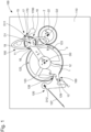
- This drive mechanism 100 comprises a structure 110, such as a plate, bridge or the like, on which is mounted an arm 1 pivoting around a main axis D0.
- This arm 1 carries a first mechanism, which comprises a satellite 10, which is pivotally mounted on the arm 1 around a first pivot axis D1, which is distant from the main axis D0.
- This satellite 10 comprises a first wheel 11, which is pivotally mounted around the first pivot axis D1 or a secondary pivot axis D11 which is parallel to it.
- the arm 1 is subjected to the restoring torque of a first energy source 12, such as a barrel, a weight system, or the like.
- a first energy source 12 such as a barrel, a weight system, or the like.
- the drive mechanism 100 further comprises at least a second energy source 22, which is arranged to subject a third mobile 3 which the drive mechanism 100 comprises to a restoring torque, directly or indirectly through a second mobile 2 mounted pivoting around a second pivot axis D2, as in the particular and non-limiting variant illustrated by the figures 1 And 2 .
- This second energy source 22 is the main energy source, and it is arranged to store more energy than the first energy source 12.
- the first wheel 11 is arranged to roll on the third mobile 3 in a regular forward rolling movement, under the action of the restoring torque of the first energy source 12.
- the satellite 10 thus constitutes a planetary mobile, which moves in rotation around the third mobile 3, around the main axis D0, always in the same direction, according to the arrow G (clockwise direction on the figure 1 ), and at constant speed.
- the third mobile 3 is arranged to remain in fixed position during a first elementary stroke of the satellite 10, and to perform a rotation, and in particular a rapid rotation, always in one direction, that of arrow B anti-clockwise on the figures 1 And 2 , during a second elementary stroke of the stroke of the satellite 10, under the action of the second energy source 22.
- the first wheel 11 drives the tourbillon cage 150 or carousel, or constitutes the tourbillon cage 150 or carousel.
- the arm 1 moves in the direction of the arrow E under the action of the first energy source 12 relative to the third mobile 3 when the latter is stopped, while that, when the third mobile 3 is recalled under the action of the second energy source 22, the arm 1, which is carried by the third mobile 3, moves retrogradely in the direction of the arrow F, relative to to the fixed structure 110, during the second elementary stroke of the satellite 10.
- the axis D1 Due to the successive rotations of the arm in the first direction of advance along the arrow E, and in the second reverse direction along the arrow F, the axis D1 performs a limited angular travel around the main axis D0.
- the first elementary stroke of the satellite 10 is much greater than the second elementary stroke of the stroke, in particular more than twenty times greater than the latter.
- the complete cycle lasts one minute, with fifty-eight seconds of slow speed travel of arm 1 in the first elementary stroke, and two seconds of rapid return of arm 1 in the first elementary stroke.
- the invention makes it possible to modulate the relationship between the first stroke part and the second elementary stroke in a different way; it is for example imaginable to obtain a first elementary stroke and a second elementary stroke that are equal.
- the drive mechanism 100 comprises stopping means 120, which are fixed on the structure 110, and which are more particularly arranged to cooperate with complementary stopping means 123 what does the third mobile 3 include for its maintenance in position, or that comprises another external mobile meshing directly or indirectly with the third mobile 3.
- the stopping means 120 comprise more particularly a trigger lever, which is arranged to cooperate successively with pins distributed on the third mobile 3, and which constitute these means of additional stop 123 in the non-limiting example illustrated by the figures 1 And 2 .
- these pins are arranged angularly in a regular manner. It is nevertheless possible to design other angular spacings to create specific displays.
- These stopping means 120 are disengageable, under the action of disengagement control means 13 which arm 1 comprises, when the first wheel 11 finishes its first elementary stroke, to authorize the pivoting of the third mobile 3 in a single direction ( arrow B anti-clockwise) under the action of the second energy source 22, causing a retrograde rotation of the arm 1 until the start of its angular travel.
- the third mobile 3 When the third mobile 3 is stopped in an angular stop position, the first wheel 11 performs a first elementary stroke, and the arm 1 moves in an angular advance stroke at a slow speed which is its display speed .
- the disengagement control means 13 disengage the stopping means 120, and the third mobile 3 is then free and subjected to the torque of the second energy source 22, directly or through the second mobile 2 depending on the construction variant chosen.
- the third mobile 3 then performs a rotation, and more particularly a sudden and almost instantaneous rotation, before returning to another angular stop position between another pin 123 and the trigger lever 120. And this rotation of the third mobile 3 causes the return retrograde arm 1 to its start position of angular travel, and in particular in the case illustrated at an accelerated speed which is much greater than its slow display speed.
- the first wheel 11 is arranged to roll inside the third mobile 3.
- Many other configurations are possible, in particular concerning the relative positions of the different pivot axes, with adapted cascades of returns.
- the operation of the drive mechanism 100 depends on the level of energy available at the second energy source 22.
- the second energy source is advantageously recharged by an automatic winding mechanism, not detailed here because it is well known to those skilled in the art: the first energy source 11 is permanently rearmed by the second energy source as long as the latter has sufficient energy, this first energy source 11 thus constitutes a buffer, and the driving of the satellite 10 by this first energy source 11 is thus a so-called constant force, or more precisely constant torque, mechanism.
- the stopping means 120 comprise a rocker, which forms a trigger lever, and which is pivotally mounted on a rocker axis D12, and which is returned in the direction of the arrow D by elastic return means 127, such as spring or similar.
- This rocker carries a rocker pin 129.
- the arm 1 comprises a ramp 13, which is arranged to cooperate with the rocker pin 129, at the end of the angular advance stroke of the arm 1, and to push the rocker in the direction of the arrow C, which makes it possible to eclipse a tip of the rocker comprising a support surface 128, which until then held in position a stop pin 123, which comprises the third mobile 3 (which comprises three at 120° in the present case).
- the third mobile 3 is then released, and can rotate, its previously immobilized pin 123 being able to pass under the arm 1.
- the position of the pins 123 directs the triggering, they guarantee the precision of the duration of a total stroke period.
- the arm 1 comprises limitation means 20, which tend to oppose the driving torque of the first energy source 12, and which are arranged to limit the rolling speed of the first wheel 11.
- limitation means 20 which tend to oppose the driving torque of the first energy source 12, and which are arranged to limit the rolling speed of the first wheel 11.
- these limitation means 20 are braking and/or friction and/or regulation means. They may in particular include aerodynamic braking means, by eddy current, or other. For example, the first 11th street may carry a seconds hand.
- the limiting means 20 are means for regulating the rolling speed of the first wheel 11 around the third mobile 3.
- the regulating mechanism is preferably at the level of the satellite 10 which constitutes a planetary mobile.
- the means for regulating the rolling speed of the first wheel 11 around the third mobile 3 comprise a stopper 17, such as an anchor or the like, and which is arranged to cooperate discontinuously with the first wheel 11, or with a synchronous mobile of the first wheel 11, or with a fourth mobile meshing directly or indirectly with the first wheel 11.
- the second pivot axis D2 is parallel to the main axis D0 and distinct from it.
- the third mobile 3 is arranged to pivot around the main axis D0.
- the satellite 10 constitutes all or part of the limitation means 20.
- the regulating member 15 comprises at least one inertial mass 1700 subjected to an alternating pivoting movement by an anchor 170, which the stopper 17 comprises, and which is arranged to cooperate with a ratchet 18 driven directly or indirectly by the first wheel 11.
- the ratchet 18 is coaxial with the first wheel 11.
- this ratchet 18 is an escape wheel.
- the first wheel 11 drives the cage of the tourbillon 150, or else constitutes the cage of the tourbillon 150.
- the axis of the resonator mechanism typically a sprung balance, that comprises the regulating member 15, coincides with the first pivot axis D1.
- the first wheel 11 drives the carousel cage or constitutes the carousel cage.
- the axis of the resonator mechanism typically a sprung balance, which the regulating member 15 comprises, is a secondary pivot axis, parallel to the first pivot axis D1, for example located at the distal end of a regulator 19 as illustrated on the figures 1 And 2 .
- the regulating member 15 comprises a regulator 19, which is driven directly or indirectly by the first wheel 1.
- this regulator 19 is synchronous with the first wheel 11, and is capable of constituting a first display of a first temporal quantity.
- the regulator 19 comprises a tourbillon or carousel cage.
- arm 1 constitutes or drives a display of a second temporal quantity.
- This arm can carry eccentric displays, for example on stars pivotally mounted on arm 1.
- the third mobile 3 constitutes or drives a display of a third temporal quantity, for example a minute display advancing in jumps.
- the second mobile 2 constitutes or drives a power reserve display.
- the invention also relates to a timepiece 1000 comprising at least one such timepiece movement 500, and which in a first variant is a watch.
- first energy source 12 and/or its second energy source 22 can conventionally comprise at least one barrel, and/or an electromechanical energy source, or other.
- the second energy source 22 is recharged by an automatic winding mechanism.
- the timepiece 1000 is static, and may in particular be a clock.
- first energy source 12 and/or its second energy source 22 can conventionally comprise at least one barrel, and/or an electromechanical energy source, or other.
- its first energy source 12 and/or its second energy source 22 comprises at least one weight, and this timepiece 1000 then comprises means for winding each weight.
- the first energy source 12 is a barrel making buffer, which makes it possible to only have to go back to the second energy source 22 which supplies the first energy source 12.
- the principle of the invention is applicable to many other variants, and to many particular applications.
- This principle is illustrated, in a simplified manner compared to the figures 1 And 2 , by the figures 4 to 9 , which only include the first energy source 12, illustrated in the form of a simple flat spring, the arm 1 carrying the first wheel 11, and the third mobile 3 on which this first wheel 11 turns.
- a tourbillon cage carried by the first wheel 11, performs one revolution per minute, the first wheel 11 moves on the third mobile 3 for approximately 18 seconds when the third mobile 3 is still in the fixed position, and continues to roll on this third mobile during the two seconds that lasts the 120° retrograde return of the third mobile 3 in the counterclockwise direction in these figures.
- FIG. 5 shows the whole in position just after such a retrograde return; there Figure 6 shows an intermediate position there Figure 7 shows the extreme angular position of arm 1 in clockwise travel, and the figure 8 illustrates the retrograde return in an anti-clockwise direction of the third mobile (visible by the change in position of marks 1, 2, 3) and of the arm 1 which it carries.
- FIG. 10 illustrates yet another variant, with an arm 1 acting as a cocking rake on a cocking barrel of the cage arm, constituting the first energy source 12, which drives the cage arm 1; under the effect of its torque, the tourbillon cage is driven and rotates on the circumference of the third mobile 3, the arm 1 moves according to the frequency and the gear ratio. Arm 1 leading the cage moves from its initial position of 0° and arrives at its maximum position of 120°.
- the second energy source 22 is unlocked, here constituted by the barrel of the basic movement of a watch.
- This barrel is in chain with a reduction mobile 223, and the latter in connection with the third mobile 3.
- the force of the barrel movement 22 will drive the reduction mobile 223 and in fact will lead the third mobile 3 into anti-rotation.
- a regulator with inverter comprising in particular a pinion, a ratchet 18, an anchor 170, is in series with the third mobile 3, and allows 'adjust the duration of the retrograde return, in particular between 1 and 10 seconds.
- the first energy source 12 here the spring of the cage arm
- the cage continues to operate by moving on the circumference of the third mobile 3.
- This variant of the Figure 10 allows the angular travel to be managed other than by the pins 123 of the variant of the figures 1 And 2 , which is replaced here by the position cog 221, it is here possible to manage other angular values, for example 360° to display a date passage, or other.
- the first energy source 12 here the spring of the cage arm, has a pre-winding giving the torque necessary for the operation of the tourbillon, this force will remain constant.
- Winding is done by the crown 220, the main barrel 22 will no longer intercede with the finishing train as in the usual technique.
- This arrangement also allows the moon to be corrected directly through the crown; it is no longer necessary to integrate a corrector integrated into the caseband.
- the invention ensures an almost constant driving force to the regulating mechanism, in particular a tourbillon or carousel cage, throughout the power reserve of the main barrel.
- THE figures 11 to 14 illustrate the wide latitude offered by the invention for the positioning of the different displays.
- the hours and minutes are read on a dial at 12 o'clock, that of the power reserve on a sector with a retrograde hand at 9 o'clock, that of the moon and/or day/night display, or even sunset, or other, at 3 o'clock, while the tourbillon has a movement of 120°, and it is possible to direct the movement of the cage over 120° according to a substantially peripheral movement as on the figures 11 and 14 , or according to a movement around an axis eccentric as much as possible as on the figures 12 and 13 , with a retrograde movement of the cage respectively from left to right, or from right to left.
- the value of 120° taken for the examples is in no way binding, the angular value depends on the desired duration of hourly travel, the value of the retrograde travel is also adjustable, for example between 2 and 5 seconds, and allows you to obtain a non-abrupt retrograde return, devoid of shock.
- the retrograde return of the cage powers the passage of the minutes.
- the retrograde return is not linked to the frequency of the resonator mechanism, and has no influence on the course of the movement.
Landscapes
- Physics & Mathematics (AREA)
- General Physics & Mathematics (AREA)
- Geometry (AREA)
- Electromechanical Clocks (AREA)
- Connection Of Motors, Electrical Generators, Mechanical Devices, And The Like (AREA)
- Structure Of Transmissions (AREA)
- Transmission Devices (AREA)
Claims (19)
- Uhrwerk (500), das mindestens ein Regulierelement (15) umfasst, das ein Tourbillon (150) oder ein Karussell ist, und einen Antriebsmechanismus (100) des Gestells des Tourbillons oder des Karussells umfasst, wobei der Mechanismus eine feste Struktur (110) umfasst, an der um eine Hauptachse (D0) schwenkbar ein Arm (1) montiert ist, der ein Planetenrad (10) trägt, das in dem Antriebsmechanismus enthalten ist, wobei das Planetenrad (10), das einen ersten Drehteil darstellt, schwenkbar am Arm (1) um eine erste Schwenkachse (D1) entfernt von der Hauptachse (D0) montiert ist und ein erstes Rad (11) umfasst, das dazu angeordnet ist, das Gestell des Tourbillons (150) oder des Karussells anzutreiben, oder das Gestell des Tourbillons (150) oder des Karussells darstellt, wobei das erste Rad (11) schwenkbar um die erste Schwenkachse (D1) oder eine dazu parallele sekundäre Schwenkachse (D11) montiert ist, wobei der Arm (1) dem Rückstelldrehmoment einer ersten Energiequelle (12) ausgesetzt ist, wobei der Antriebsmechanismus (100) außerdem mindestens eine zweite Energiequelle (22) umfasst, die dazu angeordnet ist, einen dritten Drehteil (3), der in dem Antriebsmechanismus (100) enthalten ist, direkt oder indirekt über einen zweiten Drehteil (2), der schwenkbar um eine zweite Schwenkachse (D2) montiert ist, einem Rückstellmoment auszusetzen, wobei das erste Rad (11) dazu angeordnet ist, unter der Wirkung der ersten Energiequelle (12) über den dritten Drehteil (3) in einer gleichmäßigen Vorwärtsrollbewegung in Bezug auf die feste Struktur (110) in einer einzigen Drehrichtung zu rollen, wobei der dritte Drehteil (3) dazu angeordnet ist, während eines ersten Grundwegs des Planetenrads (10) in einer festen Position zu bleiben und unter der Wirkung der zweiten Energiequelle (22) während eines zweiten Grundwegs des Wegs des Planetenrads (10) eine Drehung in nur einer Richtung auszuführen, dadurch gekennzeichnet, dass sich der Arm (1), der von dem dritten Drehteil (3) getragen wird, während des zweiten Grundwegs rückläufig in Bezug auf die feste Struktur (110) bewegt.
- Uhrwerk (500) nach Anspruch 1, dadurch gekennzeichnet, dass der Antriebsmechanismus (100) ein Anschlagmittel (120) umfasst, das dazu angeordnet ist, mit komplementären Anschlagmitteln (123) zusammenzuwirken, die im dritten Drehteil (3) enthalten sind, um ihn in Position zu halten, oder das in einem anderen externen Drehteil enthalten ist, der direkt oder indirekt mit dem dritten Drehteil (3) kämmt, wobei das Anschlagmittel (120) unter der Wirkung des Auskupplungssteuermittel (13), das im Arm (1) enthalten ist, ausgekoppelt werden kann, wenn das Planetenrad (10) seinen ersten Grundweg beendet, um das Schwenken des dritten Drehteils (3) in eine einzige Richtung unter der Wirkung der zweiten Energiequelle (22) zu ermöglichen, indem eine rückläufige Drehung des Arms (1) bis zum Beginn seines Winkelwegs angetrieben wird.
- Uhrwerk (500) nach Anspruch 1 oder 2, dadurch gekennzeichnet, dass der Arm (1) ein Begrenzungsmittel (20) umfasst, das dazu neigt, dem Antriebsdrehmoment der ersten Energiequelle (12) entgegenzuwirken, und das dazu angeordnet ist, die Rollgeschwindigkeit des ersten Rads (11) zu begrenzen.
- Uhrwerk (500) nach Anspruch 3, dadurch gekennzeichnet, dass das Begrenzungsmittel (20) ein Brems- und/oder ein Reibungs- und/oder ein Reguliermittel ist.
- Uhrwerk (500) nach Anspruch 4, dadurch gekennzeichnet, dass das Begrenzungsmittel (20) ein Reguliermittel für die Rollgeschwindigkeit des ersten Rads (11) um den dritten Drehteil (3) ist.
- Uhrwerk nach Anspruch 5, dadurch gekennzeichnet, dass das Reguliermittel für die Rollgeschwindigkeit des ersten Rads (11) um den dritten Drehteil (3) eine Anschlagvorrichtung (17) umfasst, die dazu angeordnet ist, diskontinuierlich mit dem ersten Rad (11) oder mit einem vierten Drehteil zusammenzuwirken, der direkt oder indirekt mit dem ersten Rad (11) kämmt.
- Uhrwerk (500) nach einem der Ansprüche 1 bis 6, dadurch gekennzeichnet, dass die zweite Schwenkachse (D2) parallel zur Hauptachse (D0) verläuft und sich von dieser unterscheidet.
- Uhrwerk (500) nach einem der Ansprüche 1 bis 7, dadurch gekennzeichnet, dass der dritte Drehteil (3) dazu angeordnet ist, um die Hauptachse (D0) zu schwenken.
- Uhrwerk (500) nach Anspruch 3 und einem der Ansprüche 1 bis 8, dadurch gekennzeichnet, dass das Planetenrad (10) das gesamte Begrenzungsmittel (20) oder einen Teil davon darstellt.
- Uhrwerk (500) nach Anspruch 9, dadurch gekennzeichnet, dass das Regulierelement (15) einen Resonatormechanismus mit mindestens einer Trägheitsmasse (1700) umfasst, die einer alternierenden Schwenkbewegung durch einen Anker (170) ausgesetzt ist, der mit einem Sperrrad (18) zusammenwirkt, das direkt oder indirekt durch das erste Rad (11) angetrieben wird.
- Uhrwerk (500) nach Anspruch 10, dadurch gekennzeichnet, dass das Sperrrad (18) koaxial zum ersten Rad (11) ist.
- Uhrwerk (500) nach einem der Ansprüche 9 bis 11, dadurch gekennzeichnet, dass das Regulierelement (15) einen Regulator (19) umfasst, der direkt oder indirekt durch das erste Rad (1) angetrieben wird.
- Uhrwerk (500) nach Anspruch 12, dadurch gekennzeichnet, dass der Regulator (19) mit dem ersten Rad (11) synchron ist und eine erste Anzeige einer ersten Zeitgröße darstellt.
- Uhrwerk (500) nach Anspruch 12 oder 13, dadurch gekennzeichnet, dass der Regulator (19) ein Gestell des Tourbillons oder des Karussells umfasst.
- Uhrwerk (500) nach einem der Ansprüche 1 bis 14, dadurch gekennzeichnet, dass der Arm (1) eine Anzeige einer zweiten Zeitgröße bildet oder antreibt.
- Uhrwerk (500) nach einem der Ansprüche 1 bis 15, dadurch gekennzeichnet, dass der dritte Drehteil (3) eine Anzeige einer dritten Zeitgröße bildet oder antreibt.
- Uhrwerk (500) nach einem der Ansprüche 1 bis 16, dadurch gekennzeichnet, dass der zweite Drehteil (2) eine Gangreserveanzeige bildet oder antreibt.
- Zeitmessvorrichtung (1000), die mindestens ein Uhrwerk (500) nach einem der Ansprüche 1 bis 17 umfasst.
- Teil für di Uhrmacherei (1000) nach Anspruch 18, dadurch gekennzeichnet, dass sie eine Uhr ist und dass die erste Energiequelle (12) und/oder die zweite Energiequelle (22) ein Federhaus ist.
Priority Applications (10)
| Application Number | Priority Date | Filing Date | Title |
|---|---|---|---|
| EP18185167.6A EP3599516B1 (de) | 2018-07-24 | 2018-07-24 | Retrogrades tourbillon oder karussell eines uhrwerks |
| JP2019114359A JP6796686B2 (ja) | 2018-07-24 | 2019-06-20 | 計時器用の逆行式トゥールビヨン又はカルーセル |
| US16/517,029 US11360432B2 (en) | 2018-07-24 | 2019-07-19 | Retrograde tourbillon or karussel for timepieces |
| EP19187588.9A EP3599517B1 (de) | 2018-07-24 | 2019-07-22 | Retrogrades tourbillon oder karussell eines uhrwerks |
| RU2019123139A RU2712959C1 (ru) | 2018-07-24 | 2019-07-23 | Ретроградный турбийон или карусель для часов |
| CN201910671796.6A CN110780573B (zh) | 2018-07-24 | 2019-07-24 | 钟表机芯和钟表 |
| US16/912,183 US11493884B2 (en) | 2018-07-24 | 2020-06-25 | Timepiece retrograde tourbillon or karussel |
| JP2020121197A JP7063949B2 (ja) | 2018-07-24 | 2020-07-15 | 計時器の逆行するツールビロンまたはカルーセル |
| RU2020123925A RU2742378C1 (ru) | 2018-07-24 | 2020-07-20 | Часовой ретроградный турбийон или карусель |
| CN202010710207.3A CN112286031B (zh) | 2018-07-24 | 2020-07-22 | 钟表机芯和包括钟表机芯的钟表 |
Applications Claiming Priority (1)
| Application Number | Priority Date | Filing Date | Title |
|---|---|---|---|
| EP18185167.6A EP3599516B1 (de) | 2018-07-24 | 2018-07-24 | Retrogrades tourbillon oder karussell eines uhrwerks |
Publications (2)
| Publication Number | Publication Date |
|---|---|
| EP3599516A1 EP3599516A1 (de) | 2020-01-29 |
| EP3599516B1 true EP3599516B1 (de) | 2024-04-03 |
Family
ID=63041868
Family Applications (1)
| Application Number | Title | Priority Date | Filing Date |
|---|---|---|---|
| EP18185167.6A Active EP3599516B1 (de) | 2018-07-24 | 2018-07-24 | Retrogrades tourbillon oder karussell eines uhrwerks |
Country Status (5)
| Country | Link |
|---|---|
| US (1) | US11360432B2 (de) |
| EP (1) | EP3599516B1 (de) |
| JP (1) | JP6796686B2 (de) |
| CN (1) | CN110780573B (de) |
| RU (1) | RU2712959C1 (de) |
Families Citing this family (2)
| Publication number | Priority date | Publication date | Assignee | Title |
|---|---|---|---|---|
| EP3599517B1 (de) * | 2018-07-24 | 2021-03-10 | Harry Winston SA | Retrogrades tourbillon oder karussell eines uhrwerks |
| JP7347103B2 (ja) * | 2019-10-16 | 2023-09-20 | セイコーエプソン株式会社 | 時計 |
Family Cites Families (21)
| Publication number | Priority date | Publication date | Assignee | Title |
|---|---|---|---|---|
| SU1118956A1 (ru) * | 1982-02-01 | 1984-10-15 | Пензенский Политехнический Институт | Механизм подзавода наручных часов |
| EP1528443B1 (de) * | 2003-10-28 | 2008-08-06 | Francois-Paul Journe | Konstantkraftvorrichtung für eine Uhr |
| DE602005013758D1 (de) * | 2004-04-15 | 2009-05-20 | Montres Breguet Sa Manufacture | Uhr mit mindestens zwei tourbillons |
| DE602005021883D1 (de) * | 2005-10-10 | 2010-07-29 | Montres Breguet Sa | Uhrwerk mit konstantkraftvorrichtung |
| JP4737634B2 (ja) * | 2006-08-30 | 2011-08-03 | セイコーインスツル株式会社 | 回転ケージを含む機械式時計 |
| CH701725B1 (fr) * | 2006-09-25 | 2011-03-15 | Franck Mueller Watchland S A | Tourbillon pour pièce d'horlogerie. |
| RU2456658C2 (ru) * | 2008-03-11 | 2012-07-20 | Пармиджани Флерье С.А. | Коаксиальный часовой механизм |
| DE602008003534D1 (de) * | 2008-04-30 | 2010-12-30 | Cartier Creation Studio Sa | Mechanismus zur Vermeidung der Gangvariationen aufgrund der Schwerkrafteinwirkung auf eine Reguliervorrichtung mit Unruh-Spiralfeder und mit diesem Mechanismus ausgestattete Uhr |
| CN101458494B (zh) | 2009-01-09 | 2011-06-08 | 天津海鸥表业集团有限公司 | 一种带有双擒纵机构的机械手表 |
| CH700222B1 (fr) * | 2009-01-15 | 2015-04-15 | Temps Sa Fab Du | Mouvement horloger automatique à échappement monté sur la masse oscillante. |
| CN201402375Y (zh) | 2009-03-26 | 2010-02-10 | 天津海鸥表业集团有限公司 | 带有两个陀飞轮的机械手表 |
| CH705244B1 (fr) * | 2011-07-07 | 2016-06-30 | Gfpi S A | Pièce d'horlogerie. |
| RU113594U1 (ru) * | 2011-08-10 | 2012-02-20 | Общество с ограниченной ответственностью "Константин Чайкин" | Механизм безостановочной работы часов в шаббат и часы с механизмом безостановочной работы часов в шаббат |
| EP2793087B1 (de) * | 2013-04-18 | 2016-06-01 | Glashütter Uhrenbetrieb GmbH | Tourbillon |
| CH708658A1 (fr) * | 2013-10-03 | 2015-04-15 | Gfpi S A | Mouvement d'horlogerie comprenant un engrenage différentiel entre organes réglants. |
| JP6256949B2 (ja) | 2014-03-11 | 2018-01-10 | セイコーインスツル株式会社 | 特殊表示機構、ムーブメントおよび時計 |
| EP2950164A1 (de) * | 2014-05-28 | 2015-12-02 | Omega SA | Schnellkorrektursystem einer Stundeninformation oder anderen Information |
| CH712129B1 (fr) | 2016-02-04 | 2019-12-30 | Red & White Intellectual Property Man Sa | Pièce d'horlogerie comportant un mécanisme de tourbillon. |
| CH712973B1 (de) * | 2016-09-23 | 2023-12-29 | Bucherer Ag | Tourbillon und Uhr mit Tourbillon. |
| CN206450978U (zh) | 2016-12-20 | 2017-08-29 | 天津海鸥表业集团有限公司 | 陀飞轮手表的拨针机构 |
| EP3599517B1 (de) * | 2018-07-24 | 2021-03-10 | Harry Winston SA | Retrogrades tourbillon oder karussell eines uhrwerks |
-
2018
- 2018-07-24 EP EP18185167.6A patent/EP3599516B1/de active Active
-
2019
- 2019-06-20 JP JP2019114359A patent/JP6796686B2/ja active Active
- 2019-07-19 US US16/517,029 patent/US11360432B2/en active Active
- 2019-07-23 RU RU2019123139A patent/RU2712959C1/ru active
- 2019-07-24 CN CN201910671796.6A patent/CN110780573B/zh active Active
Also Published As
| Publication number | Publication date |
|---|---|
| RU2712959C1 (ru) | 2020-02-03 |
| CN110780573A (zh) | 2020-02-11 |
| JP6796686B2 (ja) | 2020-12-09 |
| US20200033807A1 (en) | 2020-01-30 |
| US11360432B2 (en) | 2022-06-14 |
| CN110780573B (zh) | 2021-06-22 |
| EP3599516A1 (de) | 2020-01-29 |
| JP2020016641A (ja) | 2020-01-30 |
Similar Documents
| Publication | Publication Date | Title |
|---|---|---|
| EP2453322B1 (de) | Schneller Korrektor einer Zeitgrößenanzeige für Uhr | |
| EP3612896B1 (de) | Verriegelungsvorrichtung fuer uhrwerkmechanismus | |
| WO2005006087A1 (fr) | Dispositif d'affichage pour montre | |
| EP3764168B1 (de) | Uhr-anzeigemechanismus mit elastischem zeiger | |
| EP3435176B1 (de) | Drehmomentglättung für uhr mit einem schlagwerkmechanismus, insbesondere mit schlagwerkmechanismus | |
| EP3193216B1 (de) | Uhrwerksmechanismus mit tourbillon | |
| EP3059643A1 (de) | Uhrmechanismus | |
| EP3599516B1 (de) | Retrogrades tourbillon oder karussell eines uhrwerks | |
| EP3945374A1 (de) | Ansprechendes uhrenset | |
| EP3059642B1 (de) | Uhrmechanismus | |
| EP3584643A1 (de) | Augenblicklich schaltende steuervorrichtung für datumsanzeige von uhren | |
| EP3382468B1 (de) | Uhrwerk mit verlängerung der gangreserve | |
| EP3599517B1 (de) | Retrogrades tourbillon oder karussell eines uhrwerks | |
| EP3832397A1 (de) | Uhr-anzeigemechanismus mit sofortigem umspringen | |
| EP3599515B1 (de) | Antriebsmechanismus für uhrwerk | |
| CH715195B1 (fr) | Mécanisme d'entraînement d'horlogerie. | |
| CH715196B1 (fr) | Mouvement d'horlogerie comportant un bras porteur d'un satellite que comporte un tourbillon ou carrousel. | |
| EP4189493A1 (de) | Sympathische zeitnahmeanordnung | |
| EP4189495A1 (de) | Sympathische zeitnahmeanordnung | |
| CH715222A2 (fr) | Mouvement d'horlogerie comportant un bras rétrograde porteur d'une cage de tourbillon ou carrousel. | |
| CH712601A1 (fr) | Mouvement d'horlogerie comprenant un organe réglant monté dans un support mobile pivotant. | |
| EP4113215A1 (de) | Uhrwerk für uhr und uhr, die ein solches uhrwerk umfasst | |
| EP4254079A1 (de) | Mechanismus zur anzeige der mondphasen für uhr | |
| CH716894A2 (fr) | Mécanisme d'affichage d'horlogerie à saut instantané. | |
| EP2254007B1 (de) | Anzeigevorrichtung der Gangreserve für Uhr |
Legal Events
| Date | Code | Title | Description |
|---|---|---|---|
| PUAI | Public reference made under article 153(3) epc to a published international application that has entered the european phase |
Free format text: ORIGINAL CODE: 0009012 |
|
| STAA | Information on the status of an ep patent application or granted ep patent |
Free format text: STATUS: THE APPLICATION HAS BEEN PUBLISHED |
|
| AK | Designated contracting states |
Kind code of ref document: A1 Designated state(s): AL AT BE BG CH CY CZ DE DK EE ES FI FR GB GR HR HU IE IS IT LI LT LU LV MC MK MT NL NO PL PT RO RS SE SI SK SM TR |
|
| AX | Request for extension of the european patent |
Extension state: BA ME |
|
| STAA | Information on the status of an ep patent application or granted ep patent |
Free format text: STATUS: REQUEST FOR EXAMINATION WAS MADE |
|
| 17P | Request for examination filed |
Effective date: 20200729 |
|
| RBV | Designated contracting states (corrected) |
Designated state(s): AL AT BE BG CH CY CZ DE DK EE ES FI FR GB GR HR HU IE IS IT LI LT LU LV MC MK MT NL NO PL PT RO RS SE SI SK SM TR |
|
| STAA | Information on the status of an ep patent application or granted ep patent |
Free format text: STATUS: EXAMINATION IS IN PROGRESS |
|
| 17Q | First examination report despatched |
Effective date: 20210521 |
|
| STAA | Information on the status of an ep patent application or granted ep patent |
Free format text: STATUS: EXAMINATION IS IN PROGRESS |
|
| P01 | Opt-out of the competence of the unified patent court (upc) registered |
Effective date: 20230531 |
|
| GRAP | Despatch of communication of intention to grant a patent |
Free format text: ORIGINAL CODE: EPIDOSNIGR1 |
|
| STAA | Information on the status of an ep patent application or granted ep patent |
Free format text: STATUS: GRANT OF PATENT IS INTENDED |
|
| INTG | Intention to grant announced |
Effective date: 20231212 |
|
| GRAS | Grant fee paid |
Free format text: ORIGINAL CODE: EPIDOSNIGR3 |
|
| GRAA | (expected) grant |
Free format text: ORIGINAL CODE: 0009210 |
|
| STAA | Information on the status of an ep patent application or granted ep patent |
Free format text: STATUS: THE PATENT HAS BEEN GRANTED |
|
| AK | Designated contracting states |
Kind code of ref document: B1 Designated state(s): AL AT BE BG CH CY CZ DE DK EE ES FI FR GB GR HR HU IE IS IT LI LT LU LV MC MK MT NL NO PL PT RO RS SE SI SK SM TR |
|
| REG | Reference to a national code |
Ref country code: GB Ref legal event code: FG4D Free format text: NOT ENGLISH |
|
| RIN1 | Information on inventor provided before grant (corrected) |
Inventor name: BOUCHET, EMMANUEL Inventor name: BUEHLER, JOHNNY |
|
| REG | Reference to a national code |
Ref country code: CH Ref legal event code: EP |
|
| REG | Reference to a national code |
Ref country code: DE Ref legal event code: R096 Ref document number: 602018067413 Country of ref document: DE |
|
| REG | Reference to a national code |
Ref country code: IE Ref legal event code: FG4D Free format text: LANGUAGE OF EP DOCUMENT: FRENCH |
|
| PGFP | Annual fee paid to national office [announced via postgrant information from national office to epo] |
Ref country code: GB Payment date: 20240620 Year of fee payment: 7 |
|
| REG | Reference to a national code |
Ref country code: LT Ref legal event code: MG9D |
|
| PGFP | Annual fee paid to national office [announced via postgrant information from national office to epo] |
Ref country code: FR Payment date: 20240619 Year of fee payment: 7 |
|
| REG | Reference to a national code |
Ref country code: NL Ref legal event code: MP Effective date: 20240403 |
|
| REG | Reference to a national code |
Ref country code: AT Ref legal event code: MK05 Ref document number: 1673027 Country of ref document: AT Kind code of ref document: T Effective date: 20240403 |