EP3598935B1 - Vorrichtung zur erfassung biometrischer informationen und verfahren zur herstellung davon - Google Patents
Vorrichtung zur erfassung biometrischer informationen und verfahren zur herstellung davon Download PDFInfo
- Publication number
- EP3598935B1 EP3598935B1 EP19169159.1A EP19169159A EP3598935B1 EP 3598935 B1 EP3598935 B1 EP 3598935B1 EP 19169159 A EP19169159 A EP 19169159A EP 3598935 B1 EP3598935 B1 EP 3598935B1
- Authority
- EP
- European Patent Office
- Prior art keywords
- biometric information
- information detection
- detection device
- light
- sensor
- Prior art date
- Legal status (The legal status is an assumption and is not a legal conclusion. Google has not performed a legal analysis and makes no representation as to the accuracy of the status listed.)
- Active
Links
Images




Classifications
-
- A—HUMAN NECESSITIES
- A61—MEDICAL OR VETERINARY SCIENCE; HYGIENE
- A61C—DENTISTRY; APPARATUS OR METHODS FOR ORAL OR DENTAL HYGIENE
- A61C19/00—Dental auxiliary appliances
- A61C19/04—Measuring instruments specially adapted for dentistry
-
- A—HUMAN NECESSITIES
- A61—MEDICAL OR VETERINARY SCIENCE; HYGIENE
- A61B—DIAGNOSIS; SURGERY; IDENTIFICATION
- A61B5/00—Measuring for diagnostic purposes; Identification of persons
- A61B5/68—Arrangements of detecting, measuring or recording means, e.g. sensors, in relation to patient
- A61B5/6801—Arrangements of detecting, measuring or recording means, e.g. sensors, in relation to patient specially adapted to be attached to or worn on the body surface
- A61B5/6813—Specially adapted to be attached to a specific body part
- A61B5/6814—Head
- A61B5/682—Mouth, e.g., oral cavity; tongue; Lips; Teeth
-
- A—HUMAN NECESSITIES
- A61—MEDICAL OR VETERINARY SCIENCE; HYGIENE
- A61B—DIAGNOSIS; SURGERY; IDENTIFICATION
- A61B5/00—Measuring for diagnostic purposes; Identification of persons
- A61B5/0059—Measuring for diagnostic purposes; Identification of persons using light, e.g. diagnosis by transillumination, diascopy, fluorescence
- A61B5/0082—Measuring for diagnostic purposes; Identification of persons using light, e.g. diagnosis by transillumination, diascopy, fluorescence adapted for particular medical purposes
- A61B5/0088—Measuring for diagnostic purposes; Identification of persons using light, e.g. diagnosis by transillumination, diascopy, fluorescence adapted for particular medical purposes for oral or dental tissue
-
- A—HUMAN NECESSITIES
- A61—MEDICAL OR VETERINARY SCIENCE; HYGIENE
- A61B—DIAGNOSIS; SURGERY; IDENTIFICATION
- A61B5/00—Measuring for diagnostic purposes; Identification of persons
- A61B5/02—Detecting, measuring or recording for evaluating the cardiovascular system, e.g. pulse, heart rate, blood pressure or blood flow
- A61B5/024—Measuring pulse rate or heart rate
- A61B5/02416—Measuring pulse rate or heart rate using photoplethysmograph signals, e.g. generated by infrared radiation
- A61B5/02427—Details of sensor
- A61B5/02433—Details of sensor for infrared radiation
-
- A—HUMAN NECESSITIES
- A61—MEDICAL OR VETERINARY SCIENCE; HYGIENE
- A61B—DIAGNOSIS; SURGERY; IDENTIFICATION
- A61B5/00—Measuring for diagnostic purposes; Identification of persons
- A61B5/103—Measuring devices for testing the shape, pattern, colour, size or movement of the body or parts thereof, for diagnostic purposes
- A61B5/11—Measuring movement of the entire body or parts thereof, e.g. head or hand tremor or mobility of a limb
-
- A—HUMAN NECESSITIES
- A61—MEDICAL OR VETERINARY SCIENCE; HYGIENE
- A61B—DIAGNOSIS; SURGERY; IDENTIFICATION
- A61B5/00—Measuring for diagnostic purposes; Identification of persons
- A61B5/145—Measuring characteristics of blood in vivo, e.g. gas concentration or pH-value ; Measuring characteristics of body fluids or tissues, e.g. interstitial fluid or cerebral tissue
- A61B5/14532—Measuring characteristics of blood in vivo, e.g. gas concentration or pH-value ; Measuring characteristics of body fluids or tissues, e.g. interstitial fluid or cerebral tissue for measuring glucose, e.g. by tissue impedance measurement
-
- A—HUMAN NECESSITIES
- A61—MEDICAL OR VETERINARY SCIENCE; HYGIENE
- A61B—DIAGNOSIS; SURGERY; IDENTIFICATION
- A61B5/00—Measuring for diagnostic purposes; Identification of persons
- A61B5/145—Measuring characteristics of blood in vivo, e.g. gas concentration or pH-value ; Measuring characteristics of body fluids or tissues, e.g. interstitial fluid or cerebral tissue
- A61B5/1455—Measuring characteristics of blood in vivo, e.g. gas concentration or pH-value ; Measuring characteristics of body fluids or tissues, e.g. interstitial fluid or cerebral tissue using optical sensors, e.g. spectral photometrical oximeters
- A61B5/14551—Measuring characteristics of blood in vivo, e.g. gas concentration or pH-value ; Measuring characteristics of body fluids or tissues, e.g. interstitial fluid or cerebral tissue using optical sensors, e.g. spectral photometrical oximeters for measuring blood gases
-
- A—HUMAN NECESSITIES
- A61—MEDICAL OR VETERINARY SCIENCE; HYGIENE
- A61B—DIAGNOSIS; SURGERY; IDENTIFICATION
- A61B5/00—Measuring for diagnostic purposes; Identification of persons
- A61B5/145—Measuring characteristics of blood in vivo, e.g. gas concentration or pH-value ; Measuring characteristics of body fluids or tissues, e.g. interstitial fluid or cerebral tissue
- A61B5/1455—Measuring characteristics of blood in vivo, e.g. gas concentration or pH-value ; Measuring characteristics of body fluids or tissues, e.g. interstitial fluid or cerebral tissue using optical sensors, e.g. spectral photometrical oximeters
- A61B5/14551—Measuring characteristics of blood in vivo, e.g. gas concentration or pH-value ; Measuring characteristics of body fluids or tissues, e.g. interstitial fluid or cerebral tissue using optical sensors, e.g. spectral photometrical oximeters for measuring blood gases
- A61B5/14552—Details of sensors specially adapted therefor
-
- A—HUMAN NECESSITIES
- A61—MEDICAL OR VETERINARY SCIENCE; HYGIENE
- A61B—DIAGNOSIS; SURGERY; IDENTIFICATION
- A61B5/00—Measuring for diagnostic purposes; Identification of persons
- A61B5/22—Ergometry; Measuring muscular strength or the force of a muscular blow
-
- A—HUMAN NECESSITIES
- A61—MEDICAL OR VETERINARY SCIENCE; HYGIENE
- A61B—DIAGNOSIS; SURGERY; IDENTIFICATION
- A61B5/00—Measuring for diagnostic purposes; Identification of persons
- A61B5/22—Ergometry; Measuring muscular strength or the force of a muscular blow
- A61B5/224—Measuring muscular strength
- A61B5/228—Measuring muscular strength of masticatory organs, e.g. detecting dental force
-
- A—HUMAN NECESSITIES
- A61—MEDICAL OR VETERINARY SCIENCE; HYGIENE
- A61B—DIAGNOSIS; SURGERY; IDENTIFICATION
- A61B5/00—Measuring for diagnostic purposes; Identification of persons
- A61B5/45—For evaluating or diagnosing the musculoskeletal system or teeth
- A61B5/4538—Evaluating a particular part of the muscoloskeletal system or a particular medical condition
- A61B5/4542—Evaluating the mouth, e.g. the jaw
-
- A—HUMAN NECESSITIES
- A61—MEDICAL OR VETERINARY SCIENCE; HYGIENE
- A61B—DIAGNOSIS; SURGERY; IDENTIFICATION
- A61B5/00—Measuring for diagnostic purposes; Identification of persons
- A61B5/45—For evaluating or diagnosing the musculoskeletal system or teeth
- A61B5/4538—Evaluating a particular part of the muscoloskeletal system or a particular medical condition
- A61B5/4542—Evaluating the mouth, e.g. the jaw
- A61B5/4547—Evaluating teeth
-
- A—HUMAN NECESSITIES
- A61—MEDICAL OR VETERINARY SCIENCE; HYGIENE
- A61B—DIAGNOSIS; SURGERY; IDENTIFICATION
- A61B5/00—Measuring for diagnostic purposes; Identification of persons
- A61B5/45—For evaluating or diagnosing the musculoskeletal system or teeth
- A61B5/4538—Evaluating a particular part of the muscoloskeletal system or a particular medical condition
- A61B5/4542—Evaluating the mouth, e.g. the jaw
- A61B5/4552—Evaluating soft tissue within the mouth, e.g. gums or tongue
-
- A—HUMAN NECESSITIES
- A61—MEDICAL OR VETERINARY SCIENCE; HYGIENE
- A61B—DIAGNOSIS; SURGERY; IDENTIFICATION
- A61B5/00—Measuring for diagnostic purposes; Identification of persons
- A61B5/68—Arrangements of detecting, measuring or recording means, e.g. sensors, in relation to patient
- A61B5/6801—Arrangements of detecting, measuring or recording means, e.g. sensors, in relation to patient specially adapted to be attached to or worn on the body surface
- A61B5/683—Means for maintaining contact with the body
- A61B5/6835—Supports or holders, e.g., articulated arms
-
- A—HUMAN NECESSITIES
- A61—MEDICAL OR VETERINARY SCIENCE; HYGIENE
- A61B—DIAGNOSIS; SURGERY; IDENTIFICATION
- A61B2560/00—Constructional details of operational features of apparatus; Accessories for medical measuring apparatus
- A61B2560/02—Operational features
- A61B2560/0204—Operational features of power management
- A61B2560/0209—Operational features of power management adapted for power saving
-
- A—HUMAN NECESSITIES
- A61—MEDICAL OR VETERINARY SCIENCE; HYGIENE
- A61B—DIAGNOSIS; SURGERY; IDENTIFICATION
- A61B2560/00—Constructional details of operational features of apparatus; Accessories for medical measuring apparatus
- A61B2560/02—Operational features
- A61B2560/0204—Operational features of power management
- A61B2560/0214—Operational features of power management of power generation or supply
-
- A—HUMAN NECESSITIES
- A61—MEDICAL OR VETERINARY SCIENCE; HYGIENE
- A61B—DIAGNOSIS; SURGERY; IDENTIFICATION
- A61B2560/00—Constructional details of operational features of apparatus; Accessories for medical measuring apparatus
- A61B2560/04—Constructional details of apparatus
- A61B2560/0406—Constructional details of apparatus specially shaped apparatus housings
- A61B2560/0425—Ergonomically shaped housings
-
- A—HUMAN NECESSITIES
- A61—MEDICAL OR VETERINARY SCIENCE; HYGIENE
- A61B—DIAGNOSIS; SURGERY; IDENTIFICATION
- A61B2562/00—Details of sensors; Constructional details of sensor housings or probes; Accessories for sensors
- A61B2562/02—Details of sensors specially adapted for in-vivo measurements
- A61B2562/0233—Special features of optical sensors or probes classified in A61B5/00
- A61B2562/0238—Optical sensor arrangements for performing transmission measurements on body tissue
-
- A—HUMAN NECESSITIES
- A61—MEDICAL OR VETERINARY SCIENCE; HYGIENE
- A61B—DIAGNOSIS; SURGERY; IDENTIFICATION
- A61B2562/00—Details of sensors; Constructional details of sensor housings or probes; Accessories for sensors
- A61B2562/12—Manufacturing methods specially adapted for producing sensors for in-vivo measurements
-
- A—HUMAN NECESSITIES
- A61—MEDICAL OR VETERINARY SCIENCE; HYGIENE
- A61B—DIAGNOSIS; SURGERY; IDENTIFICATION
- A61B2562/00—Details of sensors; Constructional details of sensor housings or probes; Accessories for sensors
- A61B2562/18—Shielding or protection of sensors from environmental influences, e.g. protection from mechanical damage
-
- A—HUMAN NECESSITIES
- A61—MEDICAL OR VETERINARY SCIENCE; HYGIENE
- A61B—DIAGNOSIS; SURGERY; IDENTIFICATION
- A61B2562/00—Details of sensors; Constructional details of sensor housings or probes; Accessories for sensors
- A61B2562/24—Hygienic packaging for medical sensors; Maintaining apparatus for sensor hygiene
- A61B2562/247—Hygienic covers, i.e. for covering the sensor or apparatus during use
-
- A—HUMAN NECESSITIES
- A61—MEDICAL OR VETERINARY SCIENCE; HYGIENE
- A61B—DIAGNOSIS; SURGERY; IDENTIFICATION
- A61B5/00—Measuring for diagnostic purposes; Identification of persons
- A61B5/02—Detecting, measuring or recording for evaluating the cardiovascular system, e.g. pulse, heart rate, blood pressure or blood flow
- A61B5/021—Measuring pressure in heart or blood vessels
- A61B5/02108—Measuring pressure in heart or blood vessels from analysis of pulse wave characteristics
-
- A—HUMAN NECESSITIES
- A61—MEDICAL OR VETERINARY SCIENCE; HYGIENE
- A61B—DIAGNOSIS; SURGERY; IDENTIFICATION
- A61B5/00—Measuring for diagnostic purposes; Identification of persons
- A61B5/02—Detecting, measuring or recording for evaluating the cardiovascular system, e.g. pulse, heart rate, blood pressure or blood flow
- A61B5/021—Measuring pressure in heart or blood vessels
- A61B5/02141—Details of apparatus construction, e.g. pump units or housings therefor, cuff pressurising systems, arrangements of fluid conduits or circuits
-
- A—HUMAN NECESSITIES
- A61—MEDICAL OR VETERINARY SCIENCE; HYGIENE
- A61B—DIAGNOSIS; SURGERY; IDENTIFICATION
- A61B5/00—Measuring for diagnostic purposes; Identification of persons
- A61B5/02—Detecting, measuring or recording for evaluating the cardiovascular system, e.g. pulse, heart rate, blood pressure or blood flow
- A61B5/024—Measuring pulse rate or heart rate
- A61B5/02416—Measuring pulse rate or heart rate using photoplethysmograph signals, e.g. generated by infrared radiation
- A61B5/02427—Details of sensor
-
- A—HUMAN NECESSITIES
- A61—MEDICAL OR VETERINARY SCIENCE; HYGIENE
- A61B—DIAGNOSIS; SURGERY; IDENTIFICATION
- A61B5/00—Measuring for diagnostic purposes; Identification of persons
- A61B5/02—Detecting, measuring or recording for evaluating the cardiovascular system, e.g. pulse, heart rate, blood pressure or blood flow
- A61B5/024—Measuring pulse rate or heart rate
- A61B5/02438—Measuring pulse rate or heart rate with portable devices, e.g. worn by the patient
Definitions
- the present disclosure relates to a biometric information detection module configured to detect biometric information of a subject, a biometric information detection device including the same, and method of producing the same.
- US 2018/000563 discloses detection of the placement of dental aligners in a patient's mouth on teeth for indication of wearing compliance. Described are apparatuses and methods for detecting wearing, including compliance, and for transferring data, by wired or wireless direct or indirect communication of electronic compliance information to a smartphone. Also described are dental appliances that can detect physiological parameters related to respiration and sleep. Also described are aligner cases that enable NFC communication with electronic compliance indicator devices and Bluetooth communication with smartphones.
- a biometric information detection device is defined in claim 1.
- the mechanical switch can switch between a conduction state and a cutoff state, which contributes to prolonging the lifespan of the battery. Thereby, excellent long-term reliability is obtained.
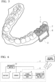
- FIG. 1 is a schematic perspective view of a schematic configuration example of a biometric information detection device 1 according to one embodiment of the present disclosure.
- FIG. 2 and FIG. 3 show a schematic cross-sectional view of a schematic configuration example of the biometric information detection device 1.
- FIG. 2 shows a cross section including a light sensor 5 (to be described below in detail) shown in FIG. 1 .
- FIG. 3 shows a cross section including a mechanical switch 12 (to be described below in detail) shown in FIG. 1.
- FIG. 2 shows a cross section taken along the line II-II shown in FIG. 1 in an arrow direction.
- FIG. 3 shows a cross section taken along the line III-III shown in FIG. 1 in an arrow direction.
- FIG. 4 is an enlarged cross-sectional view of the mechanical switch 12.
- FIG. 5 is a perspective view showing an example of a use state of the biometric information detection device 1.
- FIG. 6 is a block diagram showing a configuration of a biometric information detection module 2 included in the biometric information detection device 1.
- the biometric information detection device 1 is installed in a living body, for example, in the oral cavity, and more specifically, is installed so that it covers a part of teeth T and a part of the gums G.
- the biometric information detection device 1 includes a shell 10 that covers the teeth T and the gums G, and the biometric information detection module 2 built into the shell 10.
- the shell 10 has a has a mouthpiece shape in which an upper part 10A covering the teeth T and a lower part 10B covering the gums G are integrated, and is made of, for example, a thermoplastic polymer compound.
- a thermoplastic polymer compound for example, compounds including polyethylene, polyurethane, acrylic or the like, can be applied.
- the biometric information detection module 2 is embedded in the lower part 10B so that it is sealed from the outside. Therefore, the lower part 10B of the shell 10 is one specific example corresponding to a "sealing member" of the present disclosure.
- FIG. 1 shows a state in which a part of the shell 10 covering the biometric information detection module 2 is removed in order to improve the visibility.
- the biometric information detection module 2 is covered with the shell 10, it is not visible from the outside unless the shell 10 is transparent.
- a battery 6, the mechanical switch 12, a transmitting and receiving module 8, and the light sensor 5 are disposed on a mounting board 11 (refer to FIGS. 1, 2 , and 6 ).
- the mounting board 11 is, for example, a sheet-like flexible board on which a wiring is printed.
- the battery 6 functions as a power supply configured to supply power for driving the light sensor 5 and the transmitting and receiving module 8, to the light sensor 5 and the transmitting and receiving module 8.
- the battery 6 is, for example, a button type or coin type primary battery.
- a secondary battery may be applied as long as it can perform non-contact charging.
- the structure of the battery 6 is not particularly limited, and a laminate in which a positive electrode and a negative electrode are alternatively laminated with an electrolyte therebetween may be housed in a housing made of a metal or the like for an electrode structure, or additionally a wound structure in which the laminate is wound may be housed in a housing for an electrode structure.
- the mechanical switch 12 is disposed between the battery 6 and the transmitting and receiving module 8 on the mounting board 11, and turns supply of power from the battery 6 to the light sensor 5 and the transmitting and receiving module 8 on or off.
- the mechanical switch 12 is a so-called alternate type self-holding type switch.
- the mechanical switch 12 includes a main body 123 in which a first conductor 121 and a second conductor 122 are housed, and an operation unit 124.
- the main body 123 is a housing in which the first conductor 121 and the second conductor 122 are housed, and includes a bottom part 123A and a wall part 123B which stands along the circumference of the bottom part 123A and surrounds the first conductor 121 and the second conductor 122.
- the operation unit 124 when the operation unit 124 is operated, contact and separation between the first conductor 121 and the second conductor 122 are repeated inside the main body 123.
- the operation unit 124 is fixed to the first conductor 121, and performs a contact operation of bringing the first conductor 121 into contact with the second conductor 122 and a separation operation of separating the first conductor 121 from the second conductor 122. As shown in FIG.
- FIG. 4 shows an example in which the second conductor 122 is fixed to the main body 123, and the first conductor 121 is displaceable relative to the second conductor 122.
- the first conductor 121 in an on state is indicated by a dashed line and the first conductor 121 in an off state is indicated by a solid line.
- the transmitting and receiving module 8 includes, for example a transmitting and receiving unit 3 and a signal processing unit 4. Generally, chips in which the transmitting and receiving unit 3 and the signal processing unit 4 are integrated are distributed.
- the transmitting and receiving unit 3 is an antenna that performs wireless type data communication with a network connector 7 provided outside the biometric information detection module 2.
- the network connector 7 is a communication device, for example, a personal computer, a tablet terminal, or a smartphone, that can be connected to a network such as the Internet.
- the signal processing unit 4 is, for example, a signal processing circuit including a memory, a microprocessor, an analog-to-digital (A/D) converter, and the like.
- a detection signal (output signal) from the light sensor 5 is input to the signal processing unit 4.
- the signal processing unit 4 is driven by receiving supply of power from the battery 6, and generates a digital data signal that can be transmitted through the transmitting and receiving unit 3, based on the output signal from the light sensor 5.
- the transmitting and receiving unit 3 is driven by receiving supply of power from the battery 6, and can transmit the digital data signal wirelessly from the signal processing unit 4 to an external network through the network connector 7.
- the transmitting and receiving unit 3 can receive a control signal wirelessly from the external network through the network connector 7.
- the mounting board 11 has a rectangular planar shape, and the battery 6, the transmitting and receiving module 8, and the light sensor 5 are disposed in a row.
- the present disclosure is not limited thereto, and the layout of the battery 6, the transmitting and receiving module 8 and the light sensor 5 can be arbitrarily set.
- the light sensor 5 is, for example, a reflective photoelectric sensor, and includes a light emitting element 5A that can emit light such as a light emitting diode and a light receiving element 5B that can receive light emitted from the light emitting element 5A such as a photodiode.
- Light emitted from the light emitting element 5A has, for example, a wavelength of 400 nm or more and 1,000 nm or less.
- a part of the lower part 10B of the shell 10 covering the biometric information detection module 2, which covers the light emitting element 5A, is a first light-transmitting part 10T1 that can transmit light emitted from the light emitting element 5A (refer to FIG. 2 ).
- a part of the lower part 10B of the shell 10, which covers the light receiving element 5B, is a second light-transmitting part 10T2 that can transmit light that is reflected from the inside of the gums G or the vicinity of the surface of the gums G from light emitted from the light emitting element 5A (refer to FIG. 2 ).
- the first light-transmitting part 10T1 and the second light-transmitting part 10T2 may also be made of a thermoplastic polymer compound.
- a constituent material of the first light-transmitting part 10T1 and a constituent material of the second light-transmitting part 10T2 may be substantially the same material, and, they may be constituted using, for example, a transparent material among the above-described thermoplastic polymer compounds.
- the first light-transmitting part 10T1 and the second light-transmitting part 10T2 need not be separated, and may be continuously formed. This is advantageous for integrated formation.
- the entire lower part 10B may be transparent, and the entire shell 10 in which the upper part 10A is incorporated into the lower part 10B may be transparent.
- the first light-transmitting part 10T1 covering the light emitting element 5A and the second light-transmitting part 10T2 covering the light receiving element 5B may have light transmitting properties, and parts other than the light-transmitting part 10T may have light shielding properties or light transmitting properties.
- the light emitting element 5A is disposed to face the gums G with the first light-transmitting part 10T1 therebetween.
- the light receiving element 5B is disposed near the light emitting element 5A so that it faces the gums G with the second light-transmitting part 10T2 therebetween. Therefore, light emitted from the light emitting element 5A passes through the first light-transmitting part 10T1 of the shell 10, reaches the gums G, and is reflected at the gums G. Light reflected from the gums G passes through the second light-transmitting part 10T2 of the shell 10 and enters the light receiving element 5B. Reflected light incident on the light receiving element 5B includes, for example, biometric information such as a blood flow rate.
- the light sensor 5 is, for example, a pulse wave sensor configured to detect a pulse wave using the above biometric information, a pulse oximeter configured to detect percutaneous arterial oxygen saturation (SpOz) and a pulse rate using the above biometric information, or a glucose sensor configured to detect a glucose concentration using the above biometric information.
- the light receiving element 5B of the light sensor 5 has different light receiving wavelength ranges according to types of biometric information to be acquired.
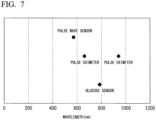
- FIG. 7 shows light receiving wavelength ranges in devices suitable for acquiring various types of biometric information. As shown in FIG.
- the light receiving element 5B that can receive light with a wavelength of about 570 nm is used for the pulse wave sensor
- the light receiving element 5B that can receive light with a wavelength of about 600 nm to 1,000 nm is used for the pulse oximeter configured to measure percutaneous arterial oxygen saturation
- the light receiving element 5B that can receive light with a wavelength of about 750 nm is used for a glucose sensor configured to detect a glucose concentration.
- FIG. 8A is an explanatory diagram showing one process of the method of producing the biometric information detection device 1
- FIG. 8B is an explanatory diagram showing one process following FIG. 8A .
- FIG. 8A and FIG. 8B are schematic diagrams showing only main members related to the explanation of this production process.
- the above biometric information detection module 2 is prepared.
- the biometric information detection module 2 is placed between two sealing films 9A and 9B made of a thermoplastic polymer compound.
- the sealing film 9A is held by a holding member 21 and the sealing film 9B is held by the holding member 21.
- a tooth form 23 matching the teeth T and the gums G of a user who will wear the biometric information detection device 1 is prepared.
- the tooth form 23 can be molded by, for example, stamping or a 3D printer.
- a part of the sealing films 9A and 9B in the vicinity of the light sensor 5 is heated to a temperature of about 280 °C by a heater 24, and as shown in FIG. 8B , the tooth form 23 is pressed against the sealing films 9A and 9B and subjected to molding.
- a heating temperature of the heater 24 is not limited to the above 280 °C, and it can be arbitrarily set, for example, within a range of 100 °C to 300 °C.
- the sealing films 9A and 9B are deformed into a shape conforming to the surface 23S of the tooth form 23 and welded. Then, when the tooth form 23 and the welded sealing films 9A and 9B are cooled, the mouthpiece-like shell 10 in which the upper part 10A and the lower part 10B are integrated is obtained. When the shell 10 is separated from the tooth form 23, the biometric information detection device 1 is obtained. In this manner, since the shell 10 in which the lower part 10B as a sealing member and the upper part 10A as a holding member are integrated is integrally formed by molding, it is possible to efficiently produce the biometric information detection device 1.
- FIG. 8A and FIG. 8B the tooth form 23 having the surface 23S with a very simplified shape is shown. However, actually, the surface 23S of the tooth form 23 has a unique shape according to each user.
- the mechanical switch 12 is provided in the biometric information detection module 2, and switches between a conduction state in which power is supplied from the battery 6 to the light sensor 5 and the transmitting and receiving module 8 and a cutoff state in which supply of the power is blocked. Therefore, the mechanical switch 12 is turned on, and power is supplied to the light sensor 5 and the transmitting and receiving module 8 only when it is desired to detect biometric information, and thus it is not necessary to constantly supply power. Therefore, it is possible to reduce power consumption, and if the battery 6 is a primary battery, it is possible to prolong the lifespan of the battery 6, and if the battery 6 is a secondary battery, it is possible to lower a charging frequency.
- biometric information detection device 1 of the present embodiment since the mechanical switch 12 is provided in the biometric information detection module 2 as described above, and a current can be applied only when it is used, actual use is possible for a long time.
- the light sensor 5 acquires an output signal including biometric information and the output signal is transmitted from the transmitting and receiving unit 3 to the network connector 7 through the signal processing unit 4, and can be additionally transmitted to an external network.
- this output signal is analyzed, it is possible to obtain specific biometric information due to a disease of a patient who is a user to whom the biometric information detection device 1 is attached.
- the first light-transmitting part 10T1 and the second light-transmitting part 10T2 are provided and emit light outside of the lower part 10B of the shell 10 and receive light from the outside. Therefore, the light sensor 5 can obtain biometric information from, for example, the teeth T and the gums G with high accuracy even if it is sealed with the shell 10.
- the sensor 5 can obtain biometric information from, for example, the teeth T and the gums G with high accuracy even if it is sealed with the shell 10.
- the light sensor 5 light is emitted to the gums G from the light emitting element 5A disposed to face the gums G, and light reflected from the gums G is detected by the light receiving element 5B disposed to face the gums G. Therefore, for example, compared with the case in which light is emitted to the skin outside the oral cavity and reflected light is detected, biometric information with higher accuracy is obtained.
- biometric information detection module 2 since the biometric information detection module 2 is always disposed in the oral cavity in a relatively stable temperature environment, biometric information with higher accuracy is obtained compared with the case in which the biometric information detection module 2 is attached outside the oral cavity, for example, to the arms and fingers.
- FIG. 9A is a perspective view of the biometric information detection module 2A when viewed from the front.
- FIG. 9B is a perspective view of the biometric information detection module 2A when viewed from the rear.
- the battery 13 includes an electrode structure 131 and an exterior member 132 enclosing the electrode structure 131.
- the electrode structure 131 is a laminate in which a positive electrode and a negative electrode are alternatively laminated with an electrolyte therebetween.
- the exterior member 132 is obtained by welding two laminated films in which a metal foil and a laminate film are adhered and has high flexibility.
- the exterior member 132 includes a main body area 132A covering the electrode structure 131 and a sealing area 132B protruding from the main body area 132A. In the sealing area 132B, the mounting board 11 on which the light sensor 5, the transmitting and receiving module 8, and the mechanical switch 12 are disposed is placed.
- the mounting board 11, the light sensor 5, and the transmitting and receiving module 8 are not shown.
- the mounting board 11 may be provided in the main body area 132A.
- the sealing area 132B is a welding margin when two laminated films are bonded to each other, and surrounds at least a part of the mechanical switch 12. More specifically, the sealing area 132B of the exterior member 132 is folded back so that it covers the mounting board 11, and has eaves parts 132B1 and 132B2 that are positioned on the side opposite to the main body area 132A of the exterior member 132 when viewed from the operation unit 124.
- the eaves parts 132B1 and 132B2 have substantially semicircular notches 13H1 and 13H2 that are provided at positions corresponding to the operation unit 124.
- the pair of notches 13H1 and 13H2 are separated from and facing each other, and form a substantially circular opening.
- the eaves part 132B1 and the eaves part 132B2 may be adhered to each other, and the pair of notches 13H1 and 13H2 may be integrated to form a circular opening.
- the operation unit 124 of the mechanical switch 12 can be operated.
- the operation unit 124 of the mechanical switch 12 it is practically difficult to operate the operation unit 124 of the mechanical switch 12 unless such a rod-like tool is used. That is, the eaves parts 132B1 and 132B2 are protective members for protection from an inadvertent operation. Therefore, according to the biometric information detection module 2A of this modified example, it is possible to reduce a likelihood of malfunction and it is possible to obtain higher operation reliability.
- FIG. 10A is a cross-sectional view showing a schematic configuration of the biometric information detection device 1A as a second modified example (Modified Example 2) of the present disclosure, and corresponds to FIG. 3 showing the biometric information detection device 1 described in the above embodiment.
- the biometric information detection device 1A has substantially the same configuration as the biometric information detection device 1 of the above embodiment except that the mechanical switch 12A is mounted in place of the mechanical switch 12.
- FIG. 10B shows an enlarged cross section configuration of the mechanical switch 12A.
- a protective part 123G is additionally provided in the main body 123.
- the protective part 123G is, for example, a wall-like part that is provided at a tip of the wall part 123B, and as shown in FIG. 10B , an upper end 123T ( FIG. 10B ) thereof, that is, an end on the side opposite to the bottom part 123A, protrudes from an upper end 124T of the operation unit 124 to the side opposite to the bottom part 123A. Therefore, as shown in FIG.
- a first part 101 covering the operation unit 124 is recessed more than a second part 102 covering the periphery of the operation unit 124.
- a first part 101 covering the operation unit 124 is recessed more than a second part 102 covering the periphery of the operation unit 124.
- the upper part 10A as a holding member and the lower part 10B as a sealing member are integrally formed by molding using the tooth form 23.
- a configuration of the biometric information detection device 1B as a third modified example (Modified Example 3) of the present disclosure shown in FIG. 11 may be used.
- a holding member 25 such as a metal fitting engaging with teeth T is boned to the shell 10C in which the biometric information detection module 2 is embedded.
- a hole 2H into which the teeth T is inserted when it is mounted in the oral cavity is provided in the oral cavity.
- the biometric information detection device 1B is produced by, for example, producing the shell 10 C according to the above vacuum forming and bonding the holding member 25 to the shell 10C.
- the biometric information detection device 1 of the above embodiment emits light to the gums G, receives light reflected from the gums G, and thus detects biometric information.
- a biometric information detection device 1C of a fourth modified example (Modified Example 4) of the present disclosure shown in FIG. 12 emits light to an inner surface of a cheek CH in the oral cavity, receives light reflected from the inner surface of the cheek CH, and thus detects biometric information.
- the biometric information detection device 1C the light emitting element 5A is disposed to face the cheek CH with the first light-transmitting part 10T1 therebetween, and the light receiving element 5B is disposed near the light emitting element 5A so that it faces the cheek CH with the second light-transmitting part 10T2 therebetween. Therefore, the light-transmitting part 10T of the lower part 10B of the shell 10 covering the biometric information detection module 2 is provided on the side opposite to the gums G with the biometric information detection module 2 therebetween. Except for these points, the biometric information detection device 1C has substantially the same configuration as the biometric information detection device 1 of the above embodiment. Also in the biometric information detection device 1C, the same effects as in the biometric information detection device 1 of the above embodiment are obtained. For example, the biometric information detection device 1C of this modified example is beneficial when it is determined that a surface structure of the gums G of a subject is not favorable and it is difficult to obtain stable biometric information.
- FIG. 13 is a cross-sectional view showing a schematic configuration of a biometric information detection device 1D as a fifth modified example (Modified Example 5) of the present disclosure.
- a strain sensor 31 is embedded in a part of the shell 10 covering a crown part TA of the teeth T.
- the strain sensor 31 is connected to the battery 6 through a power line and is connected to the signal processing unit 4 through a communication line.
- the strain sensor 31 receives supply of power from the battery 6 and transmits a detection signal to the signal processing unit 4. Except for these points, the biometric information detection device 1D has substantially the same configuration as the biometric information detection device 1 of the above embodiment.
- the same effects as in the biometric information detection device 1 of the above embodiment are obtained.
- the strain sensor 31 it is possible to measure the biting strength when the teeth of the upper jaw and the teeth of the lower jaw of a subject are engaged and the pressure of the cheek or tongue of a subject in contact with the strain sensor 31.
- information such as the biting strength and the pressure of the cheek and tongue is used, it is possible to obtain structural strength information and teeth alignment information necessary for artificial teeth, for example, dentures and implants.
- the strain sensor 31 for example, a magnetostriction sensor using magnetostriction can be applied.
- a pressure sensor using a piezoelectric element or the like can be applied in place of the strain sensor 31.
- FIG. 14 is a perspective view showing a schematic configuration of a biometric information detection device 1E as a sixth modified example (Modified Example 6) of the present disclosure.
- an acceleration sensor 32 is additionally provided in the biometric information detection module 2.
- the acceleration sensor 32 is connected to the battery 6 through a power line and is connected to the signal processing unit 4 through a communication line.
- the acceleration sensor 32 receives supply of power from the battery 6 and transmits a detection signal to the signal processing unit 4.
- the biometric information detection device 1E has substantially the same configuration as the biometric information detection device 1 of the above embodiment. Therefore, also in the biometric information detection device 1E, the same effects as in the biometric information detection device 1 of the above embodiment are obtained.
- the acceleration sensor 32 when the acceleration sensor 32 is provided, for example, it is possible to detect a movement of the lower jaw with respect to the upper jaw of the subject. When a relative movement between the upper jaw and the lower jaw is detected, for example, it is possible to obtain structural strength information necessary for artificial teeth such as dentures and implants and this may be used for diagnosis of the presence of jaw joint abnormalities.
- a gyro sensor may be used in place of the acceleration sensor 32.
- the biometric information detection device 1 having the shell 10 mounted so that it covers two consecutive crown parts
- the biometric information detection device of the present disclosure is not limited thereto.
- the biometric information detection device of the present disclosure may have, for example, a shell mounted so that it covers only one crown part or a shell mounted so that it covers three or more crown parts.
- the biometric information detection device of the present disclosure may include two or more sensors.
- the biometric information detection device may be mounted on both the upper jaw and the lower jaw.
- the biometric information detection module and the biometric information detection device of the present disclosure are not limited thereto. They may be installed in a living body outside of the oral cavity, for example, in the abdominal cavity. Alternatively, it may be attached to the outside of a living body such as the skin surface rather than the inside of a living body. However, the biometric information detection device according to the invention is configured to be installed in an oral cavity.
Landscapes
- Health & Medical Sciences (AREA)
- Life Sciences & Earth Sciences (AREA)
- Physics & Mathematics (AREA)
- Engineering & Computer Science (AREA)
- Veterinary Medicine (AREA)
- Public Health (AREA)
- General Health & Medical Sciences (AREA)
- Animal Behavior & Ethology (AREA)
- Biophysics (AREA)
- Biomedical Technology (AREA)
- Molecular Biology (AREA)
- Heart & Thoracic Surgery (AREA)
- Medical Informatics (AREA)
- Pathology (AREA)
- Surgery (AREA)
- Dentistry (AREA)
- Oral & Maxillofacial Surgery (AREA)
- Physical Education & Sports Medicine (AREA)
- Orthopedic Medicine & Surgery (AREA)
- Rheumatology (AREA)
- Optics & Photonics (AREA)
- Cardiology (AREA)
- Physiology (AREA)
- Spectroscopy & Molecular Physics (AREA)
- Emergency Medicine (AREA)
- Audiology, Speech & Language Pathology (AREA)
- Epidemiology (AREA)
- Measurement Of The Respiration, Hearing Ability, Form, And Blood Characteristics Of Living Organisms (AREA)
- Measuring Pulse, Heart Rate, Blood Pressure Or Blood Flow (AREA)
- Measuring And Recording Apparatus For Diagnosis (AREA)
Claims (12)
- Vorrichtung (1D) zum Erfassen von biometrischen Informationen, die dafür konfiguriert ist, in einer Mundhöhle installiert zu werden, wobei sie Folgendes umfasst:einen Sensor (5),eine Batterie (6, 13) undeinen mechanischen Schalter (12), der zwischen einem Leitungszustand, in dem Energie von der Batterie (6, 13) dem Sensor (5) zugeführt wird, und einem Ausschaltzustand, in dem die Zufuhr von Energie gesperrt ist, umschaltet, wobei die Vorrichtung (1D) zum Erfassen von biometrischen Informationen ferner Folgendes umfasst:ein Abdichtungselement (10B), das den Sensor (5), die Batterie (6, 13) und den mechanischen Schalter (12) alle abdichtet und Zahnfleisch in der Mundhöhle zu bedecken,ein Halteelement (10A), das dafür konfiguriert ist, Zähne (T) in der Mundhöhle zu bedecken, und das mit dem Abdichtungselement (10B) integriert ist,einen Dehnungssensor (31) undeine Signalverarbeitungseinheit (4), die mit dem Abdichtungselement (10B) abgedichtet ist, dafür konfiguriert ist, eine Zufuhr von Energie von der Batterie (6, 13) zu empfangen, und dafür konfiguriert ist, ein Datensignal auf Grundlage eines Ausgangssignals von dem Sensor (5) zu erzeugen,wobeider mechanische Schalter (12, 12A) eine Bedienungseinheit (124) einschließt, die mit dem Abdichtungselement (10B, 10C) abgedichtet ist und die so positioniert ist, dass sie durch das Zahnfleisch (G) getragen wird, wenn die Vorrichtung zum Erfassen von biometrischen Informationen in der Mundhöhle installiert ist, wobei die Bedienungseinheit dafür konfiguriert ist, eine Schiebebetätigung anzunehmen,der mechanische Schalter (12, 12A) ein Schalter von der selbsthaltenden Art ist,der mechanische Schalter (12, 12A) ferner einen Hauptkörper (123), einen ersten Leiter (121) und einen zweiten Leiter (122) einschließt, wobei der Hauptkörper (123) den ersten Leiter (121) und den zweiten Leiter (122) aufnimmt,die Bedienungseinheit (124) dafür konfiguriert ist, eine Kontaktbetätigung des Bringens des ersten Leiters (121) in Kontakt mit dem zweiten Leiter (122) und eine Trennbetätigung des Trennens des ersten Leiters (121) von dem zweiten Leiter (122) durchzuführen, undder Dehnungssensor (31) durch eine Stromleitung mit der Batterie (6, 13) verbunden ist und durch eine Kommunikationsleitung mit der Signalverarbeitungseinheit (4) verbunden ist, wobei der Dehnungssensor dafür konfiguriert ist, eine Zufuhr von Energie von der Batterie zu empfangen und ein Erfassungssignal an die Signalverarbeitungseinheit zu übermitteln, wobei die Vorrichtung dadurch gekennzeichnet ist, dassder Dehnungssensor (31) in dem Haltelement an einer Position eingebettet ist, die dafür konfiguriert ist, einen Kronenteil der Zähne zu bedecken, wenn die Vorrichtung zum Erfassen von biometrischen Informationen in der Mundhöhle installiert ist.
- Vorrichtung (1D) zum Erfassen von biometrischen Informationen nach Anspruch 1,wobei die Batterie (13) Folgendes aufweist: eine Elektrodenstruktur (131) und ein äußeres Element (132), das einen Hauptkörperbereich (132A), der die Elektrodenstruktur (131) bedeckt, und einen Abdichtungsbereich (132B), der von dem Hauptkörperbereich (132A) aus vorspringt und in dem die Elektrodenstruktur (131) eingeschlossen ist, einschließt, undwobei der Abdichtungsbereich (132B) des äußeren Elements (132) zumindest einen Teil des mechanischen Schalters (12) umschließt.
- Vorrichtung (1D) zum Erfassen von biometrischen Informationen nach Anspruch 2,wobei die Bedienungseinheit (124) in dem Hauptkörperbereich (132A) oder dem Abdichtungsbereich (132B) des äußeren Elements (132) bereitgestellt wird,wobei der Abdichtungsbereich (132B) des äußeren Elements (132) einen Traufenteil (132B1, 132B2) aufweist, der in einer Ansicht von der Bedienungseinheit (124) aus auf der zu dem Hauptkörperbereich (132A) des äußeren Elements (132) entgegengesetzten Seite angeordnet ist, undwobei der Traufenteil (132B1, 132B2) eine Öffnung oder eine Kerbe (13H1, 13H2) aufweist, die an einer Position bereitgestellt wird, die der Bedienungseinheit (124) entspricht.
- Vorrichtung (1D) zum Erfassen von biometrischen Informationen nach Ansprüche 1 bis 3,wobei der Sensor (5) ein Licht emittierendes Element (5A), das dazu in der Lage ist, Licht zu emittieren, und ein Licht aufnehmendes Element (5B), das dazu in der Lage ist, das Licht aufzunehmen, das von dem Licht emittierenden Element (5A) emittiert wird, einschließt, undwobei das Abdichtungselement (10B) einen ersten Licht durchlassenden Teil (10T1), der das Licht emittierende Element (5A) bedeckt und dazu in der Lage ist, das Licht durchzulassen, und einen zweiten Licht durchlassenden Teil (10T2), der das Licht aufnehmende Element (5B) bedeckt und dazu in der Lage ist, das Licht durchzulassen, einschließt.
- Vorrichtung (1D) zum Erfassen von biometrischen Informationen nach Anspruch 4,wobei das Licht emittierende Element (5A) dafür konfiguriert ist, so angeordnet zu werden, dass es mit dem ersten Licht durchlassenden Teil (10T1) dazwischen zu dem Zahnfleisch in der Mundhöhle zeigt, undwobei das Licht aufnehmende Element (5B) so angeordnet ist, dass es mit dem zweiten Licht durchlassenden Teil (10T2) dazwischen zu dem Zahnfleisch in der Mundhöhle zeigt.
- Vorrichtung (1D) zum Erfassen von biometrischen Informationen nach Anspruch 4 oder Anspruch 5,
wobei das Licht eine Wellenlänge von 400 nm oder mehr und 1 000 nm oder weniger aufweist. - Vorrichtung (1D) zum Erfassen von biometrischen Informationen nach Ansprüche 4 bis 6, die ferner Folgendes umfasst:
eine Sende- und Empfangseinheit (3), die mit dem Abdichtungselement (10B, 10C) abgedichtet ist und eine Zufuhr von Energie von der Batterie (6, 13) empfängt, dazu in der Lage ist, das Datensignal von der Signalverarbeitungseinheit (4) zu einer externen Vorrichtung (7) zu übermitteln, und dazu in der Lage ist, ein Steuersignal von der externen Vorrichtung (7) zu empfangen. - Vorrichtung (1D) zum Erfassen von biometrischen Informationen nach Ansprüche 4 bis 7,
wobei der erste Licht durchlassende Teil (10T1) und der zweite Licht durchlassende Teil (10T2) aus einer thermoplastischen Polymerverbindung geformt sind. - Vorrichtung (1D) zum Erfassen von biometrischen Informationen nach Ansprüche 1 bis 8,
wobei der Sensor (5) ein Pulswellensensor, ein Pulsoximeter oder ein Glukosesensor ist. - Vorrichtung (1D) zum Erfassen von biometrischen Informationen nach Ansprüche 1 bis 9,
wobei das Halteelement (10A) und das Abdichtungselement (10B) ein integral geformtes Mundstück sind. - Verfahren zum Herstellen der Vorrichtung (1D) zum Erfassen von biometrischen Informationen nach Anspruch 1, wobei das Verfahren Folgendes umfasst:Vorbereiten des Sensors (5), der Batterie (6, 13) und des mechanischen Schalters (12, 12A),Einsetzen des Sensors (5), der Batterie (6, 13) und des mechanischen Schalters (12, 12A) zwischen einem Paar von Abdichtungsfolien (9A, 9B), danach Erwärmen und Formen des Paares von Abdichtungsfolien (9A, 9B) und dadurch Formen eines Abdichtungselements (10B), mit dem der Sensor (5), die Batterie (6, 13) und der mechanische Schalter (12, 12A) abgedichtet werden, undFormen des Halteelements (10A, 25).
- Verfahren zum Herstellen der Vorrichtung (1D) zum Erfassen von biometrischen Informationen nach Anspruch 11,
wobei das Abdichtungselement (10B) und das Halteelement (10A) durch das Formen integral geformt werden.
Applications Claiming Priority (1)
| Application Number | Priority Date | Filing Date | Title |
|---|---|---|---|
| JP2018141422A JP7104939B2 (ja) | 2018-07-27 | 2018-07-27 | 生体情報検出装置およびその製造方法、生体情報検出モジュールおよびその製造方法 |
Publications (2)
| Publication Number | Publication Date |
|---|---|
| EP3598935A1 EP3598935A1 (de) | 2020-01-29 |
| EP3598935B1 true EP3598935B1 (de) | 2023-08-02 |
Family
ID=66182368
Family Applications (1)
| Application Number | Title | Priority Date | Filing Date |
|---|---|---|---|
| EP19169159.1A Active EP3598935B1 (de) | 2018-07-27 | 2019-04-15 | Vorrichtung zur erfassung biometrischer informationen und verfahren zur herstellung davon |
Country Status (4)
| Country | Link |
|---|---|
| US (1) | US11317864B2 (de) |
| EP (1) | EP3598935B1 (de) |
| JP (1) | JP7104939B2 (de) |
| CN (1) | CN110755082B (de) |
Families Citing this family (7)
| Publication number | Priority date | Publication date | Assignee | Title |
|---|---|---|---|---|
| US11478343B2 (en) * | 2017-12-06 | 2022-10-25 | Seungki MIN | Apparatus configured to be attachable and detachable to and from oral cavity |
| JP7329338B2 (ja) * | 2019-03-05 | 2023-08-18 | セイコーグループ株式会社 | 口腔内生体モニタリング装置 |
| JP7602762B2 (ja) * | 2020-03-13 | 2024-12-19 | セイコーグループ株式会社 | 口腔内センシング装置及びその製造方法 |
| GB2622897B (en) * | 2020-06-05 | 2025-02-19 | Orb Innovations Ltd | Fitness monitoring and tracking device |
| US20220008242A1 (en) * | 2020-07-10 | 2022-01-13 | Robert Graham Kitchell | Methods of Reducing Sleep Disordered Breathing and Structures Formed Therapy |
| JP2025037720A (ja) * | 2023-09-06 | 2025-03-18 | セイコーグループ株式会社 | 口腔内光センサ |
| DE102024116965B4 (de) * | 2024-06-17 | 2026-02-26 | Institut Straumann Ag | Technik zur Herstellung einer individuell angepassten intelligenten Dentalvorrichtung und individuell angepasste intelligente Dentalvorrichtung |
Citations (1)
| Publication number | Priority date | Publication date | Assignee | Title |
|---|---|---|---|---|
| US20060166157A1 (en) * | 2001-10-01 | 2006-07-27 | Tariq Rahman | Compliance monitor and method for a medical device |
Family Cites Families (11)
| Publication number | Priority date | Publication date | Assignee | Title |
|---|---|---|---|---|
| JP4518591B2 (ja) * | 1999-05-31 | 2010-08-04 | 三洋電機株式会社 | 薄型電池を内蔵するパック電池 |
| WO2001058349A1 (en) * | 2000-02-11 | 2001-08-16 | U.S. Army Institute Of Surgical Research | Pacifier pulse oximeter sensor |
| CN1279874C (zh) * | 2002-05-01 | 2006-10-18 | 松下电器产业株式会社 | 活体信息测量用接触装置 |
| JP4264472B2 (ja) | 2002-11-22 | 2009-05-20 | 達次 西原 | 口腔内設置型生体モニター・治療装置 |
| US20090210032A1 (en) * | 2004-07-23 | 2009-08-20 | Ben Zion Beiski | Manufacturing methods, testing methods, and testers for intra-oral electronically embedded devices |
| JP2009284985A (ja) * | 2008-05-27 | 2009-12-10 | Panasonic Electric Works Co Ltd | 歯科漂白用マウスピースおよびその製造方法 |
| JP2011212117A (ja) * | 2010-03-31 | 2011-10-27 | Terumo Corp | 体液成分測定システム |
| AU2012249600B2 (en) * | 2011-04-26 | 2016-05-19 | Incube Labs, Llc | Mouthpiece for measurement of biometric data of a diver and underwater communication |
| JP2016200895A (ja) * | 2015-04-08 | 2016-12-01 | 三菱電機株式会社 | 情報通信端末 |
| EP4670634A3 (de) * | 2016-06-17 | 2026-01-21 | Align Technology, Inc. | System zur bestimmung der patientenkonformität mit einem orthodontischen behandlungs- oder retentionsplan |
| JP6853683B2 (ja) * | 2016-06-27 | 2021-03-31 | 医療法人社団皓有会 | 血中酸素飽和度測定装置 |
-
2018
- 2018-07-27 JP JP2018141422A patent/JP7104939B2/ja active Active
-
2019
- 2019-04-15 US US16/384,029 patent/US11317864B2/en active Active
- 2019-04-15 EP EP19169159.1A patent/EP3598935B1/de active Active
- 2019-05-10 CN CN201910388602.1A patent/CN110755082B/zh active Active
Patent Citations (1)
| Publication number | Priority date | Publication date | Assignee | Title |
|---|---|---|---|---|
| US20060166157A1 (en) * | 2001-10-01 | 2006-07-27 | Tariq Rahman | Compliance monitor and method for a medical device |
Also Published As
| Publication number | Publication date |
|---|---|
| JP7104939B2 (ja) | 2022-07-22 |
| US11317864B2 (en) | 2022-05-03 |
| CN110755082B (zh) | 2024-06-07 |
| EP3598935A1 (de) | 2020-01-29 |
| US20200029898A1 (en) | 2020-01-30 |
| CN110755082A (zh) | 2020-02-07 |
| JP2020014771A (ja) | 2020-01-30 |
Similar Documents
| Publication | Publication Date | Title |
|---|---|---|
| US11317864B2 (en) | Biometric information detection device and method of producing the same, biometric information detection module and method of producing the same | |
| EP3598934A1 (de) | Vorrichtung zur erfassung biometrischer informationen und verfahren zur herstellung davon und modul zur erfassung biometrischer informationen und verfahren zur herstellung davon | |
| US10918290B2 (en) | Multi-channel vitals device | |
| US8413502B2 (en) | Device for measuring infant feeding performance | |
| US8956289B2 (en) | Vital information measuring device | |
| JP5549793B1 (ja) | 生体情報測定装置、生体情報測定装置の測定部、生体情報測定装置の指受け部、およびパルスオキシメータ | |
| CN209529110U (zh) | 一种生命体征实时监测手环 | |
| EP3656344A1 (de) | Am zahn zu befestigende tragbare vorrichtung und die am zahn zu befestigende messvorrichtung | |
| JP2012125455A (ja) | 口腔内撮像装置 | |
| JP7170987B2 (ja) | 生体情報検出装置およびその製造方法 | |
| JP7097569B2 (ja) | 生体情報検出装置およびその製造方法 | |
| US8319401B2 (en) | Air movement energy harvesting with wireless sensors | |
| CN115734749A (zh) | 医疗传感器中的传感器接头包套 | |
| JP6914793B2 (ja) | パルスフォトメトリ用プローブ | |
| JP7126159B2 (ja) | 生体情報検出モジュールおよびそれを備えた生体情報検出装置、生体情報検出モジュールの製造方法、ならびに生体情報検出装置の製造方法 | |
| CN114305327B (zh) | 活体监视装置 | |
| CN114305352A (zh) | 活体监视装置 | |
| JP2005287547A (ja) | 接触式センサ及び接触式センサ実装の計測システム | |
| EP3725216A1 (de) | Wearable-sensor | |
| ES3037166T3 (en) | Integration system of sensing consumables for wearable devices | |
| CN215128519U (zh) | 一种外接手机的健康管理装置 | |
| CN112690785A (zh) | 口腔原位柔性检测装置及其制造方法 | |
| US20240358327A1 (en) | Intra-oral devices and methods for making and using them | |
| RU207002U1 (ru) | Устройство мониторинга показателей жизнедеятельности ребёнка | |
| WO2022234145A1 (en) | Monitoring apparatus |
Legal Events
| Date | Code | Title | Description |
|---|---|---|---|
| PUAI | Public reference made under article 153(3) epc to a published international application that has entered the european phase |
Free format text: ORIGINAL CODE: 0009012 |
|
| STAA | Information on the status of an ep patent application or granted ep patent |
Free format text: STATUS: THE APPLICATION HAS BEEN PUBLISHED |
|
| AK | Designated contracting states |
Kind code of ref document: A1 Designated state(s): AL AT BE BG CH CY CZ DE DK EE ES FI FR GB GR HR HU IE IS IT LI LT LU LV MC MK MT NL NO PL PT RO RS SE SI SK SM TR |
|
| AX | Request for extension of the european patent |
Extension state: BA ME |
|
| STAA | Information on the status of an ep patent application or granted ep patent |
Free format text: STATUS: REQUEST FOR EXAMINATION WAS MADE |
|
| 17P | Request for examination filed |
Effective date: 20200701 |
|
| RBV | Designated contracting states (corrected) |
Designated state(s): AL AT BE BG CH CY CZ DE DK EE ES FI FR GB GR HR HU IE IS IT LI LT LU LV MC MK MT NL NO PL PT RO RS SE SI SK SM TR |
|
| STAA | Information on the status of an ep patent application or granted ep patent |
Free format text: STATUS: EXAMINATION IS IN PROGRESS |
|
| 17Q | First examination report despatched |
Effective date: 20200909 |
|
| RAP1 | Party data changed (applicant data changed or rights of an application transferred) |
Owner name: SEIKO HOLDINGS KABUSHIKI KAISHA (TRADING AS SEIKO HOLDINGS CORPORATION) Owner name: SHOWA UNIVERSITY |
|
| GRAP | Despatch of communication of intention to grant a patent |
Free format text: ORIGINAL CODE: EPIDOSNIGR1 |
|
| STAA | Information on the status of an ep patent application or granted ep patent |
Free format text: STATUS: GRANT OF PATENT IS INTENDED |
|
| RIC1 | Information provided on ipc code assigned before grant |
Ipc: A61B 5/024 20060101ALN20221108BHEP Ipc: A61B 5/021 20060101ALN20221108BHEP Ipc: A61B 5/1455 20060101ALI20221108BHEP Ipc: A61B 5/00 20060101AFI20221108BHEP |
|
| INTG | Intention to grant announced |
Effective date: 20221125 |
|
| INTG | Intention to grant announced |
Effective date: 20221207 |
|
| RAP3 | Party data changed (applicant data changed or rights of an application transferred) |
Owner name: SHOWA UNIVERSITY Owner name: SEIKO GROUP CORPORATION |
|
| GRAJ | Information related to disapproval of communication of intention to grant by the applicant or resumption of examination proceedings by the epo deleted |
Free format text: ORIGINAL CODE: EPIDOSDIGR1 |
|
| STAA | Information on the status of an ep patent application or granted ep patent |
Free format text: STATUS: EXAMINATION IS IN PROGRESS |
|
| GRAP | Despatch of communication of intention to grant a patent |
Free format text: ORIGINAL CODE: EPIDOSNIGR1 |
|
| STAA | Information on the status of an ep patent application or granted ep patent |
Free format text: STATUS: GRANT OF PATENT IS INTENDED |
|
| INTC | Intention to grant announced (deleted) | ||
| RIC1 | Information provided on ipc code assigned before grant |
Ipc: A61B 5/024 20060101ALN20230220BHEP Ipc: A61B 5/021 20060101ALN20230220BHEP Ipc: A61B 5/1455 20060101ALI20230220BHEP Ipc: A61B 5/00 20060101AFI20230220BHEP |
|
| INTG | Intention to grant announced |
Effective date: 20230316 |
|
| GRAS | Grant fee paid |
Free format text: ORIGINAL CODE: EPIDOSNIGR3 |
|
| GRAA | (expected) grant |
Free format text: ORIGINAL CODE: 0009210 |
|
| STAA | Information on the status of an ep patent application or granted ep patent |
Free format text: STATUS: THE PATENT HAS BEEN GRANTED |
|
| AK | Designated contracting states |
Kind code of ref document: B1 Designated state(s): AL AT BE BG CH CY CZ DE DK EE ES FI FR GB GR HR HU IE IS IT LI LT LU LV MC MK MT NL NO PL PT RO RS SE SI SK SM TR |
|
| REG | Reference to a national code |
Ref country code: GB Ref legal event code: FG4D |
|
| REG | Reference to a national code |
Ref country code: CH Ref legal event code: EP |
|
| REG | Reference to a national code |
Ref country code: DE Ref legal event code: R096 Ref document number: 602019033869 Country of ref document: DE |
|
| REG | Reference to a national code |
Ref country code: IE Ref legal event code: FG4D |
|
| REG | Reference to a national code |
Ref country code: LT Ref legal event code: MG9D |
|
| REG | Reference to a national code |
Ref country code: NL Ref legal event code: MP Effective date: 20230802 |
|
| REG | Reference to a national code |
Ref country code: AT Ref legal event code: MK05 Ref document number: 1593718 Country of ref document: AT Kind code of ref document: T Effective date: 20230802 |
|
| PG25 | Lapsed in a contracting state [announced via postgrant information from national office to epo] |
Ref country code: GR Free format text: LAPSE BECAUSE OF FAILURE TO SUBMIT A TRANSLATION OF THE DESCRIPTION OR TO PAY THE FEE WITHIN THE PRESCRIBED TIME-LIMIT Effective date: 20231103 |
|
| PG25 | Lapsed in a contracting state [announced via postgrant information from national office to epo] |
Ref country code: IS Free format text: LAPSE BECAUSE OF FAILURE TO SUBMIT A TRANSLATION OF THE DESCRIPTION OR TO PAY THE FEE WITHIN THE PRESCRIBED TIME-LIMIT Effective date: 20231202 |
|
| PG25 | Lapsed in a contracting state [announced via postgrant information from national office to epo] |
Ref country code: SE Free format text: LAPSE BECAUSE OF FAILURE TO SUBMIT A TRANSLATION OF THE DESCRIPTION OR TO PAY THE FEE WITHIN THE PRESCRIBED TIME-LIMIT Effective date: 20230802 Ref country code: RS Free format text: LAPSE BECAUSE OF FAILURE TO SUBMIT A TRANSLATION OF THE DESCRIPTION OR TO PAY THE FEE WITHIN THE PRESCRIBED TIME-LIMIT Effective date: 20230802 Ref country code: PT Free format text: LAPSE BECAUSE OF FAILURE TO SUBMIT A TRANSLATION OF THE DESCRIPTION OR TO PAY THE FEE WITHIN THE PRESCRIBED TIME-LIMIT Effective date: 20231204 Ref country code: NO Free format text: LAPSE BECAUSE OF FAILURE TO SUBMIT A TRANSLATION OF THE DESCRIPTION OR TO PAY THE FEE WITHIN THE PRESCRIBED TIME-LIMIT Effective date: 20231102 Ref country code: NL Free format text: LAPSE BECAUSE OF FAILURE TO SUBMIT A TRANSLATION OF THE DESCRIPTION OR TO PAY THE FEE WITHIN THE PRESCRIBED TIME-LIMIT Effective date: 20230802 Ref country code: LV Free format text: LAPSE BECAUSE OF FAILURE TO SUBMIT A TRANSLATION OF THE DESCRIPTION OR TO PAY THE FEE WITHIN THE PRESCRIBED TIME-LIMIT Effective date: 20230802 Ref country code: LT Free format text: LAPSE BECAUSE OF FAILURE TO SUBMIT A TRANSLATION OF THE DESCRIPTION OR TO PAY THE FEE WITHIN THE PRESCRIBED TIME-LIMIT Effective date: 20230802 Ref country code: IS Free format text: LAPSE BECAUSE OF FAILURE TO SUBMIT A TRANSLATION OF THE DESCRIPTION OR TO PAY THE FEE WITHIN THE PRESCRIBED TIME-LIMIT Effective date: 20231202 Ref country code: HR Free format text: LAPSE BECAUSE OF FAILURE TO SUBMIT A TRANSLATION OF THE DESCRIPTION OR TO PAY THE FEE WITHIN THE PRESCRIBED TIME-LIMIT Effective date: 20230802 Ref country code: GR Free format text: LAPSE BECAUSE OF FAILURE TO SUBMIT A TRANSLATION OF THE DESCRIPTION OR TO PAY THE FEE WITHIN THE PRESCRIBED TIME-LIMIT Effective date: 20231103 Ref country code: FI Free format text: LAPSE BECAUSE OF FAILURE TO SUBMIT A TRANSLATION OF THE DESCRIPTION OR TO PAY THE FEE WITHIN THE PRESCRIBED TIME-LIMIT Effective date: 20230802 Ref country code: AT Free format text: LAPSE BECAUSE OF FAILURE TO SUBMIT A TRANSLATION OF THE DESCRIPTION OR TO PAY THE FEE WITHIN THE PRESCRIBED TIME-LIMIT Effective date: 20230802 |
|
| PG25 | Lapsed in a contracting state [announced via postgrant information from national office to epo] |
Ref country code: PL Free format text: LAPSE BECAUSE OF FAILURE TO SUBMIT A TRANSLATION OF THE DESCRIPTION OR TO PAY THE FEE WITHIN THE PRESCRIBED TIME-LIMIT Effective date: 20230802 |
|
| PG25 | Lapsed in a contracting state [announced via postgrant information from national office to epo] |
Ref country code: ES Free format text: LAPSE BECAUSE OF FAILURE TO SUBMIT A TRANSLATION OF THE DESCRIPTION OR TO PAY THE FEE WITHIN THE PRESCRIBED TIME-LIMIT Effective date: 20230802 |
|
| PG25 | Lapsed in a contracting state [announced via postgrant information from national office to epo] |
Ref country code: SM Free format text: LAPSE BECAUSE OF FAILURE TO SUBMIT A TRANSLATION OF THE DESCRIPTION OR TO PAY THE FEE WITHIN THE PRESCRIBED TIME-LIMIT Effective date: 20230802 Ref country code: RO Free format text: LAPSE BECAUSE OF FAILURE TO SUBMIT A TRANSLATION OF THE DESCRIPTION OR TO PAY THE FEE WITHIN THE PRESCRIBED TIME-LIMIT Effective date: 20230802 Ref country code: ES Free format text: LAPSE BECAUSE OF FAILURE TO SUBMIT A TRANSLATION OF THE DESCRIPTION OR TO PAY THE FEE WITHIN THE PRESCRIBED TIME-LIMIT Effective date: 20230802 Ref country code: EE Free format text: LAPSE BECAUSE OF FAILURE TO SUBMIT A TRANSLATION OF THE DESCRIPTION OR TO PAY THE FEE WITHIN THE PRESCRIBED TIME-LIMIT Effective date: 20230802 Ref country code: DK Free format text: LAPSE BECAUSE OF FAILURE TO SUBMIT A TRANSLATION OF THE DESCRIPTION OR TO PAY THE FEE WITHIN THE PRESCRIBED TIME-LIMIT Effective date: 20230802 Ref country code: CZ Free format text: LAPSE BECAUSE OF FAILURE TO SUBMIT A TRANSLATION OF THE DESCRIPTION OR TO PAY THE FEE WITHIN THE PRESCRIBED TIME-LIMIT Effective date: 20230802 Ref country code: SK Free format text: LAPSE BECAUSE OF FAILURE TO SUBMIT A TRANSLATION OF THE DESCRIPTION OR TO PAY THE FEE WITHIN THE PRESCRIBED TIME-LIMIT Effective date: 20230802 |
|
| REG | Reference to a national code |
Ref country code: DE Ref legal event code: R097 Ref document number: 602019033869 Country of ref document: DE |
|
| PG25 | Lapsed in a contracting state [announced via postgrant information from national office to epo] |
Ref country code: IT Free format text: LAPSE BECAUSE OF FAILURE TO SUBMIT A TRANSLATION OF THE DESCRIPTION OR TO PAY THE FEE WITHIN THE PRESCRIBED TIME-LIMIT Effective date: 20230802 |
|
| PLBE | No opposition filed within time limit |
Free format text: ORIGINAL CODE: 0009261 |
|
| STAA | Information on the status of an ep patent application or granted ep patent |
Free format text: STATUS: NO OPPOSITION FILED WITHIN TIME LIMIT |
|
| 26N | No opposition filed |
Effective date: 20240503 |
|
| PG25 | Lapsed in a contracting state [announced via postgrant information from national office to epo] |
Ref country code: SI Free format text: LAPSE BECAUSE OF FAILURE TO SUBMIT A TRANSLATION OF THE DESCRIPTION OR TO PAY THE FEE WITHIN THE PRESCRIBED TIME-LIMIT Effective date: 20230802 |
|
| PG25 | Lapsed in a contracting state [announced via postgrant information from national office to epo] |
Ref country code: BG Free format text: LAPSE BECAUSE OF FAILURE TO SUBMIT A TRANSLATION OF THE DESCRIPTION OR TO PAY THE FEE WITHIN THE PRESCRIBED TIME-LIMIT Effective date: 20230802 |
|
| PG25 | Lapsed in a contracting state [announced via postgrant information from national office to epo] |
Ref country code: MC Free format text: LAPSE BECAUSE OF FAILURE TO SUBMIT A TRANSLATION OF THE DESCRIPTION OR TO PAY THE FEE WITHIN THE PRESCRIBED TIME-LIMIT Effective date: 20230802 |
|
| PG25 | Lapsed in a contracting state [announced via postgrant information from national office to epo] |
Ref country code: MC Free format text: LAPSE BECAUSE OF FAILURE TO SUBMIT A TRANSLATION OF THE DESCRIPTION OR TO PAY THE FEE WITHIN THE PRESCRIBED TIME-LIMIT Effective date: 20230802 Ref country code: BG Free format text: LAPSE BECAUSE OF FAILURE TO SUBMIT A TRANSLATION OF THE DESCRIPTION OR TO PAY THE FEE WITHIN THE PRESCRIBED TIME-LIMIT Effective date: 20230802 |
|
| REG | Reference to a national code |
Ref country code: CH Ref legal event code: PL |
|
| PG25 | Lapsed in a contracting state [announced via postgrant information from national office to epo] |
Ref country code: LU Free format text: LAPSE BECAUSE OF NON-PAYMENT OF DUE FEES Effective date: 20240415 |
|
| REG | Reference to a national code |
Ref country code: BE Ref legal event code: MM Effective date: 20240430 |
|
| PG25 | Lapsed in a contracting state [announced via postgrant information from national office to epo] |
Ref country code: LU Free format text: LAPSE BECAUSE OF NON-PAYMENT OF DUE FEES Effective date: 20240415 |
|
| PG25 | Lapsed in a contracting state [announced via postgrant information from national office to epo] |
Ref country code: BE Free format text: LAPSE BECAUSE OF NON-PAYMENT OF DUE FEES Effective date: 20240430 |
|
| PG25 | Lapsed in a contracting state [announced via postgrant information from national office to epo] |
Ref country code: BE Free format text: LAPSE BECAUSE OF NON-PAYMENT OF DUE FEES Effective date: 20240430 Ref country code: CH Free format text: LAPSE BECAUSE OF NON-PAYMENT OF DUE FEES Effective date: 20240430 |
|
| PG25 | Lapsed in a contracting state [announced via postgrant information from national office to epo] |
Ref country code: IE Free format text: LAPSE BECAUSE OF NON-PAYMENT OF DUE FEES Effective date: 20240415 |
|
| PGFP | Annual fee paid to national office [announced via postgrant information from national office to epo] |
Ref country code: DE Payment date: 20250305 Year of fee payment: 7 |
|
| PG25 | Lapsed in a contracting state [announced via postgrant information from national office to epo] |
Ref country code: CY Free format text: LAPSE BECAUSE OF FAILURE TO SUBMIT A TRANSLATION OF THE DESCRIPTION OR TO PAY THE FEE WITHIN THE PRESCRIBED TIME-LIMIT; INVALID AB INITIO Effective date: 20190415 |
|
| PG25 | Lapsed in a contracting state [announced via postgrant information from national office to epo] |
Ref country code: HU Free format text: LAPSE BECAUSE OF FAILURE TO SUBMIT A TRANSLATION OF THE DESCRIPTION OR TO PAY THE FEE WITHIN THE PRESCRIBED TIME-LIMIT; INVALID AB INITIO Effective date: 20190415 |
|
| REG | Reference to a national code |
Ref country code: DE Ref legal event code: R081 Ref document number: 602019033869 Country of ref document: DE Owner name: SEIKO GROUP CORPORATION, JP Free format text: FORMER OWNERS: SEIKO GROUP CORPORATION, TOKYO, JP; SHOWA UNIVERSITY, TOKYO, SHINAGAWA-KU, JP Ref country code: DE Ref legal event code: R081 Ref document number: 602019033869 Country of ref document: DE Owner name: SHOWA MEDICAL UNIVERSITY, TOKYO, JP Free format text: FORMER OWNERS: SEIKO GROUP CORPORATION, TOKYO, JP; SHOWA UNIVERSITY, TOKYO, SHINAGAWA-KU, JP |
|
| PGFP | Annual fee paid to national office [announced via postgrant information from national office to epo] |
Ref country code: GB Payment date: 20260313 Year of fee payment: 8 |
|
| PGFP | Annual fee paid to national office [announced via postgrant information from national office to epo] |
Ref country code: FR Payment date: 20260309 Year of fee payment: 8 |