EP3598564B1 - Passive schutzbatteriemodulstruktur und herstellungsverfahren dafür - Google Patents
Passive schutzbatteriemodulstruktur und herstellungsverfahren dafür Download PDFInfo
- Publication number
- EP3598564B1 EP3598564B1 EP17900751.3A EP17900751A EP3598564B1 EP 3598564 B1 EP3598564 B1 EP 3598564B1 EP 17900751 A EP17900751 A EP 17900751A EP 3598564 B1 EP3598564 B1 EP 3598564B1
- Authority
- EP
- European Patent Office
- Prior art keywords
- fireproof
- thermally insulating
- insulating spacer
- battery cells
- battery
- Prior art date
- Legal status (The legal status is an assumption and is not a legal conclusion. Google has not performed a legal analysis and makes no representation as to the accuracy of the status listed.)
- Active
Links
Images

Classifications
-
- H—ELECTRICITY
- H01—ELECTRIC ELEMENTS
- H01M—PROCESSES OR MEANS, e.g. BATTERIES, FOR THE DIRECT CONVERSION OF CHEMICAL ENERGY INTO ELECTRICAL ENERGY
- H01M10/00—Secondary cells; Manufacture thereof
- H01M10/04—Construction or manufacture in general
-
- H—ELECTRICITY
- H01—ELECTRIC ELEMENTS
- H01M—PROCESSES OR MEANS, e.g. BATTERIES, FOR THE DIRECT CONVERSION OF CHEMICAL ENERGY INTO ELECTRICAL ENERGY
- H01M10/00—Secondary cells; Manufacture thereof
- H01M10/60—Heating or cooling; Temperature control
- H01M10/61—Types of temperature control
- H01M10/613—Cooling or keeping cold
-
- H—ELECTRICITY
- H01—ELECTRIC ELEMENTS
- H01M—PROCESSES OR MEANS, e.g. BATTERIES, FOR THE DIRECT CONVERSION OF CHEMICAL ENERGY INTO ELECTRICAL ENERGY
- H01M10/00—Secondary cells; Manufacture thereof
- H01M10/04—Construction or manufacture in general
- H01M10/0468—Compression means for stacks of electrodes and separators
-
- H—ELECTRICITY
- H01—ELECTRIC ELEMENTS
- H01M—PROCESSES OR MEANS, e.g. BATTERIES, FOR THE DIRECT CONVERSION OF CHEMICAL ENERGY INTO ELECTRICAL ENERGY
- H01M10/00—Secondary cells; Manufacture thereof
- H01M10/60—Heating or cooling; Temperature control
- H01M10/62—Heating or cooling; Temperature control specially adapted for specific applications
- H01M10/625—Vehicles
-
- H—ELECTRICITY
- H01—ELECTRIC ELEMENTS
- H01M—PROCESSES OR MEANS, e.g. BATTERIES, FOR THE DIRECT CONVERSION OF CHEMICAL ENERGY INTO ELECTRICAL ENERGY
- H01M10/00—Secondary cells; Manufacture thereof
- H01M10/60—Heating or cooling; Temperature control
- H01M10/64—Heating or cooling; Temperature control characterised by the shape of the cells
- H01M10/647—Prismatic or flat cells, e.g. pouch cells
-
- H—ELECTRICITY
- H01—ELECTRIC ELEMENTS
- H01M—PROCESSES OR MEANS, e.g. BATTERIES, FOR THE DIRECT CONVERSION OF CHEMICAL ENERGY INTO ELECTRICAL ENERGY
- H01M10/00—Secondary cells; Manufacture thereof
- H01M10/60—Heating or cooling; Temperature control
- H01M10/65—Means for temperature control structurally associated with the cells
- H01M10/658—Means for temperature control structurally associated with the cells by thermal insulation or shielding
-
- H—ELECTRICITY
- H01—ELECTRIC ELEMENTS
- H01M—PROCESSES OR MEANS, e.g. BATTERIES, FOR THE DIRECT CONVERSION OF CHEMICAL ENERGY INTO ELECTRICAL ENERGY
- H01M50/00—Constructional details or processes of manufacture of the non-active parts of electrochemical cells other than fuel cells, e.g. hybrid cells
- H01M50/20—Mountings; Secondary casings or frames; Racks, modules or packs; Suspension devices; Shock absorbers; Transport or carrying devices; Holders
- H01M50/233—Mountings; Secondary casings or frames; Racks, modules or packs; Suspension devices; Shock absorbers; Transport or carrying devices; Holders characterised by physical properties of casings or racks, e.g. dimensions
- H01M50/24—Mountings; Secondary casings or frames; Racks, modules or packs; Suspension devices; Shock absorbers; Transport or carrying devices; Holders characterised by physical properties of casings or racks, e.g. dimensions adapted for protecting batteries from their environment, e.g. from corrosion
-
- H—ELECTRICITY
- H01—ELECTRIC ELEMENTS
- H01M—PROCESSES OR MEANS, e.g. BATTERIES, FOR THE DIRECT CONVERSION OF CHEMICAL ENERGY INTO ELECTRICAL ENERGY
- H01M2200/00—Safety devices for primary or secondary batteries
- H01M2200/10—Temperature sensitive devices
-
- H—ELECTRICITY
- H01—ELECTRIC ELEMENTS
- H01M—PROCESSES OR MEANS, e.g. BATTERIES, FOR THE DIRECT CONVERSION OF CHEMICAL ENERGY INTO ELECTRICAL ENERGY
- H01M2220/00—Batteries for particular applications
- H01M2220/20—Batteries in motive systems, e.g. vehicle, ship, plane
-
- Y—GENERAL TAGGING OF NEW TECHNOLOGICAL DEVELOPMENTS; GENERAL TAGGING OF CROSS-SECTIONAL TECHNOLOGIES SPANNING OVER SEVERAL SECTIONS OF THE IPC; TECHNICAL SUBJECTS COVERED BY FORMER USPC CROSS-REFERENCE ART COLLECTIONS [XRACs] AND DIGESTS
- Y02—TECHNOLOGIES OR APPLICATIONS FOR MITIGATION OR ADAPTATION AGAINST CLIMATE CHANGE
- Y02E—REDUCTION OF GREENHOUSE GAS [GHG] EMISSIONS, RELATED TO ENERGY GENERATION, TRANSMISSION OR DISTRIBUTION
- Y02E60/00—Enabling technologies; Technologies with a potential or indirect contribution to GHG emissions mitigation
- Y02E60/10—Energy storage using batteries
-
- Y—GENERAL TAGGING OF NEW TECHNOLOGICAL DEVELOPMENTS; GENERAL TAGGING OF CROSS-SECTIONAL TECHNOLOGIES SPANNING OVER SEVERAL SECTIONS OF THE IPC; TECHNICAL SUBJECTS COVERED BY FORMER USPC CROSS-REFERENCE ART COLLECTIONS [XRACs] AND DIGESTS
- Y02—TECHNOLOGIES OR APPLICATIONS FOR MITIGATION OR ADAPTATION AGAINST CLIMATE CHANGE
- Y02P—CLIMATE CHANGE MITIGATION TECHNOLOGIES IN THE PRODUCTION OR PROCESSING OF GOODS
- Y02P70/00—Climate change mitigation technologies in the production process for final industrial or consumer products
- Y02P70/50—Manufacturing or production processes characterised by the final manufactured product
Definitions
- the present application relates to PACK for power batteries, more particularly to a battery module structure with passive protection and a fabrication method thereof.
- the ternary battery is advantageous over the phosphoric acid iron batteries in energy densities, but worse in safety.
- the latest announced subsidies for new energy vehicles are tightly linked to the energy density of battery systems of electric vehicles, but the traditional phosphoric acid iron batteries cannot meet higher requirements for the energy density.
- a battery pack includes a plurality of secondary batteries, a housing for containing the secondary batteries, and at least one heat insulating layer for separating the secondary batteries from one another.
- the at least one heat insulating layer includes a foam material capable of foaming at a first predetermined temperature of 110°C, or more and less than 200°C, and the thickness of the heat insulating layer increases when the foam material foams.
- the at least one heat insulating layer includes heat insulating layers each of which is disposed on a surface of each of the secondary batteries. The thickness of the heat insulating layers before the foam material foams is 0.1 to 3 mm.
- a battery module includes a plurality of single cells stacked in sequence along the arrangement direction (D), and the heat insulation pad is bonded between the two adjacent single cells by glue coated on the positive and negative surfaces.
- the heat insulation pad is provided with a through hole for receiving glue, and the glue in the through hole is bonded to two adjacent single cells.
- Each cell has the end faces which are used for bonding the heat insulation pad located on both sides of the cell along the arrangement direction (D), and the side surfaces located on both sides of the cell along the front and rear directions (F).
- a battery module with passive protection structure and a fabrication method thereof are provided by the present invention as a technical solution to the deficiencies of the prior art, which improve the safety of the ternary batteries and delay or even avoid a chain reaction caused by an overheated individual battery cell.
- the present invention provides a battery module structure with passive protection, comprising: a plurality of battery cells 4, a fireproof and thermally insulating spacer 3 and a casing; the plurality of battery cells 4 are arranged in the casing, and the fireproof and thermally insulating spacer 3 is provided between the battery cells 4; and the fireproof and thermally insulating spacer 3 comprises a substrate coated with a fireproof and thermally insulating coating made of a material that foams when heated.
- the substrate of the fireproof and thermally insulating spacer 3 is a mica sheet; whereas, the mica sheet contains more than 90% mica and has a bending strength of at least 160 MPa; a thickness of the mica sheet is 0.2 mm with an error range of 0.02 mm; and a thickness of the fireproof and thermally insulating coating is 0.3 mm with an error range of 0.03 mm; and the mica sheet is coated with the fireproof and thermally insulating coating on one side, and the other side of the mica sheet is coated with an adhesive to bond with a battery cell 4 adjacent to the fireproof and thermally insulating spacer.
- the fireproof and thermally insulating coating of the fireproof and thermally insulating spacer 3 is evenly coated on the substrate and foams to absorb a heat conducted by the substrate at a preset temperature.
- the present invention provides a fabrication method of the battery module structure with passive protection, comprising the following steps:
- the fabrication method further comprises: after a fireproof and thermally insulating coating is applied on the substrate of the fireproof and thermally insulating spacer 3, performing a corona treatment on the fireproof thermal insulation coating.
- the battery module structure with passive protection and the fabrication method thereof are provided by the present invention.
- the battery cells of the battery module are respectively spaced by the fireproof and thermally insulating spacer; and an excellent thermal insulation is achieved by the fireproof and thermally insulating spacer due to a mica sheet and the endothermic foaming of the fireproof and thermally insulating coating when heated, such that the risk of having a thermal runaway or even breaking the explosion-proof valve when the battery cells are overheated is effectively delayed or avoided in case that the adjacent battery cell is overcharged or has a thermal runaway under a high temperature. This gives sufficient time for people in the vehicle to evacuate, ensuring the personnel safety.
- a battery module with passive protection which comprises a plurality of battery cells 4, a fireproof and thermally insulating spacer 3 and a casing.
- the battery cells 4 are provided in the casing, and the fireproof and thermally insulating spacer 3 is provided between the battery cells 4 and comprises a substrate 31 coated with a fireproof and thermally insulating coating 32 made of a material that foams when heated.
- the battery cells in the battery module are respectively spaced by the fireproof and thermally insulating spacer 3.
- An excellent thermal insulation can be achieved by the fireproof and thermally insulating spacer 3 due to a mica sheet and the endothermic foaming of the fireproof and thermally insulating coating when heated, such that the risk of having a thermal runaway or even breaking the explosion-proof valve when the battery cells are overheated can be effectively delayed or avoided in case that the adjacent battery cell is overcharged or has a thermal runaway under a high temperature. This gives sufficient time for people in the vehicle to evacuate, ensuring the personnel safety.
- the substrate 31 of the fireproof and thermally insulating spacer 3 is a mica sheet; a thickness of the mica sheet is 0.2 mm with an error range of 0.02 mm, e.g. the thickness of the substrate 31 could be 0.2 mm.
- the thickness of the fireproof and thermally insulating coating could be 0.3mm with an error range of 0.03 mm, e.g. the thickness of the fireproof and thermally insulating coating could be 0.3 mm.
- the mica sheet is coated with the fireproof and thermally insulating coating on one side, and the other side of mica sheet is covered with an adhesive. The adhesive fixes the fireproof and thermally insulating spacer 3 with a battery cell 4 by bonding.
- the fireproof and thermally insulating coating 31 of the fireproof and thermally insulating spacer 3 is evenly coated on the substrate 31 and massively absorbs the heat conducted by the substrate by foaming rapidly at a preset temperature (e.g. at a temperature of 120°C), and the purpose of fireproofing and thermal insulation is achieved through the chemical foaming mechanism.
- the casing comprises end plates 1 on both ends and a side plate 2 on a side.
- the battery cells 4, the fireproof and thermally insulating spacer 3 provided therebetween and the end plates 1 on both ends are integrally bonded by a double-sided adhesive with a high viscosity; and the end plates 1 are riveted with the side plate 2 through a rivet, such that the battery cells 4 and the fireproof and thermally insulating spacer 3 are packaged in the casing.
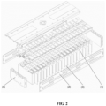
- the battery module with passive protection has various embodiments, and a preferred embodiment of the battery module with passive protection will be described in detail with reference to FIGS. 1-4 .
- a battery module with passive protection with 20 battery cells comprising two end plates 1, two side plates 2, 19 fireproof and thermally insulating spacers 3 and 20 ternary VDA battery cells 4.
- Each end of the 20 ternary VDA battery cells 4 is arranged with an end plate 1.
- the ternary VDA battery cell 4 and the fireproof and thermally insulating spacers 3 are pressed to a desire size by a pressure device and are firmly bonded by a double-sided adhesive.
- the end plates 1 are riveted with the side plates 2 through a rivet.
- the 20 ternary VDA battery cells 4 are respectively spaced by the fireproof and thermally insulating spacers 3, and with the adhesive 33 on the fireproof thermally and insulating spacer 3 and the double-sided adhesive with the high viscosity, the ternary VDA battery cells 4 are firmly bonded with the fireproof and thermally insulating spacers 3.
- the size of a rivet hole on the side plate 2 is designed to be sufficient when the ternary VDA battery cells 4 and the fireproof and thermally insulating spacers 3 are pressed to a desired size with a preset pressure that is over 100Kg, such that the side plates 2 are riveted with the end plates 1 by a stainless steel rivet of shear resistance as a whole frame after the rivet holes on the side plates 2 aligned with the rivet holes on the end plates 1.
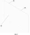
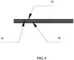
- the fireproof and thermally insulating spacer 3 comprises a mica sheet substrate 31, the fireproof and thermally insulating coating 32 and the adhesive 33 on a back of the mica sheet.
- the mica sheet substrate 31 contains more than 90% mica and has a bending strength of at least 160 MPa, which provides a sufficient mechanical strength while having a great thermal insulation and insulation performance, so the required strength of the substrate for applying the fireproof and thermally insulating coatings is reached.
- the chemical compositions of the fireproof and thermally insulating coating 32 has a polymer structure which can rapidly foam at a high temperature to absorb a large amount of heat, achieving the purpose of fireproofing and thermal insulation through a chemical foaming mechanism.
- the double-sided adhesive between the ternary VDA battery cell 4 and the fireproof and thermally insulating spacer 3 and the adhesive 33 on the fireproof and thermally insulating spacer 3 are required to withstand a high temperature of at least 80°C and with a viscosity larger than 24 hrs/0.5 Kg.
- the safety of the battery module is greatly improved by providing a spacer excellent in fireproofing and thermal insulating between the ternary VDA battery cells of the battery module with passive protection of the embodiment, which prevents the abnormality of one battery cell from spreading over the whole battery module and causes no threat to personnel safety.
- Step 102 the battery cells 4 and the fireproof and thermally insulating spacers 3 are bonded via the double-sided adhesive with a high viscosity and are fixed by a pressure transferred from the end plates 1 on both ends.
- the fabrication method further comprises the following steps: after the fireproof and thermally insulating coating is applied on the substrate of the fireproof and thermally insulating spacer 3, the corona treatment is performed on the fireproof and thermally insulating coating, such that the battery cell is firmly bonded with the double-sided adhesive.
- the fabrication method is provided based on the battery module with passive protection provided in the first aspect. It should be noted that the fabrication method will change as the battery module with passive protection changes, so it will not be limited herein.
- the battery cells in the battery module are respectively spaced by the fireproof and thermally insulating spacers.
- An excellent thermal insulation can be achieved by the fireproof and thermally insulating spacers due to a mica sheet and the endothermic foaming of the fireproof and thermally insulating coating when heated, such that the risk of having a thermal runaway or even breaking the explosion-proof valve when the battery cells are overheated can be effectively delayed or avoided in case that the adjacent battery cell is overcharged or has a thermal runaway under a high temperature. This gives sufficient time for people in the vehicle to evacuate, ensuring the personnel safety.
- the present invention provides a battery module with passive protection and a fabrication thereof, relating to PACK of the power battery.
- the cells in the battery module are respectively spaced by the fireproof and thermally insulating spacers.
- An excellent thermal insulation can be provided by the fireproof and thermally insulating spacer due to a mica sheet and the endothermic foaming of the fireproof and thermally insulating coating when heated, such that the risk of having a thermal runaway or even breaking the explosion-proof valve when the battery cells are overheated can be effectively delayed or avoided in case that the adjacent battery cell is overcharged or has a thermal runaway under a high temperature, which gives sufficient time for people in the vehicle to evacuate, thus ensuring the personnel safety. Therefore, the present application has excellent industrial application prospects.
Landscapes
- Chemical & Material Sciences (AREA)
- Chemical Kinetics & Catalysis (AREA)
- Electrochemistry (AREA)
- General Chemical & Material Sciences (AREA)
- Engineering & Computer Science (AREA)
- Manufacturing & Machinery (AREA)
- Battery Mounting, Suspending (AREA)
- Secondary Cells (AREA)
Claims (4)
- Batteriemodulstruktur mit passivem Schutz, die eine Vielzahl von Batteriezellen (4), einen feuerfesten und wärmedämmenden Abstandshalter (3) und ein Gehäuse umfasst;dadurch gekennzeichnet, dass die Batteriezellen (4) in dem Gehäuse angeordnet sind und der feuerfeste und wärmedämmende Abstandshalter (3) zwischen den Batteriezellen (4) vorgesehen ist; unddass der feuerfeste und wärmedämmende Abstandshalter (3) ein Substrat (31) umfasst, das mit einer feuerfesten und wärmedämmenden Beschichtung (32) aus einem Material beschichtet ist, das bei Erwärmung aufschäumt;dass das Substrat (31) des feuerfesten und wärmedämmenden Abstandshalters (3) eine Glimmerfolie ist, wobei die Glimmerfolie mehr als 90 % Glimmer enthält und eine Biegefestigkeit von mindestens 160 MPa aufweist, wobei eine Dicke der Glimmerfolie 0,2 mm mit einem Fehlerbereich von 0,02 mm beträgt; wobei eine Dicke der feuerfesten und wärmedämmenden Beschichtung (32) 0,3 mm mit einem Fehlerbereich von 0,03 mm beträgt; unddass die Glimmerfolie auf einer Seite mit der feuerfesten und wärmedämmenden Beschichtung (32) beschichtet ist und die andere Seite der Glimmerfolie mit einem Klebstoff (33) beschichtet ist, um sie mit einer an das feuerfeste und wärmedämmenden Abstandshalter (3) angrenzenden Batteriezelle (4) zu verbinden.
- Batteriemodulstruktur nach Anspruch 1, dadurch gekennzeichnet, dass die feuerfeste und wärmedämmende Beschichtung des feuerfesten und wärmedämmenden Abstandshalters (3) gleichmäßig auf das Substrat (31) aufgetragen ist und aufschäumt, um eine durch das Substrat bei einer vorgegebenen Temperatur geleitete Wärme zu aufzunehmen.
- Herstellungsverfahren der Batteriemodulstruktur nach einem der Ansprüche 1-2, umfassend:Bereitstellen der Batteriezellen (4) im Gehäuse;Befestigen des feuerfesten und wärmedämmenden Abstandshalters (3) zwischen den Batteriezellen (4); wobei der feuerfeste und wärmedämmenden Abstandshalter (3) das mit der feuerfesten und wärmedämmenden Beschichtung aufgetragene Substrat umfasst, das aus dem Material besteht, das bei Erwärmung aufschäumt; undAufbringen eines Drucks, der größer als ein voreingestellter Druck ist, auf die Batteriezellen (4) über die Endplatten (1) an beiden Enden des Gehäuses, um die Endplatten (1) an beiden Enden in Richtung der Batteriezellen (4) zu bewegen, und Fixieren der Endplatten (1) mit der Seitenplatte (2) des Gehäuses durch den Niet nach Erreichen einer Grenzposition.
- Herstellungsverfahren nach Anspruch 3, das ferner umfasst:
nach dem Aufbringen einer feuerfesten und wärmedämmenden Beschichtung auf das Substrat des feuerfesten und wärmeisolierenden Abstandshalters (3), Durchführen einer Koronabehandlung auf der feuerfesten wärmedämmenden Beschichtung.
Applications Claiming Priority (2)
| Application Number | Priority Date | Filing Date | Title |
|---|---|---|---|
| CN201710150039.5A CN106785225A (zh) | 2017-03-14 | 2017-03-14 | 被动防护电池模组结构及其制作方法 |
| PCT/CN2017/109409 WO2018166216A1 (zh) | 2017-03-14 | 2017-11-03 | 被动防护电池模组结构及其制作方法 |
Publications (4)
| Publication Number | Publication Date |
|---|---|
| EP3598564A1 EP3598564A1 (de) | 2020-01-22 |
| EP3598564A4 EP3598564A4 (de) | 2020-12-02 |
| EP3598564B1 true EP3598564B1 (de) | 2023-07-19 |
| EP3598564C0 EP3598564C0 (de) | 2023-07-19 |
Family
ID=58962628
Family Applications (1)
| Application Number | Title | Priority Date | Filing Date |
|---|---|---|---|
| EP17900751.3A Active EP3598564B1 (de) | 2017-03-14 | 2017-11-03 | Passive schutzbatteriemodulstruktur und herstellungsverfahren dafür |
Country Status (3)
| Country | Link |
|---|---|
| EP (1) | EP3598564B1 (de) |
| CN (1) | CN106785225A (de) |
| WO (1) | WO2018166216A1 (de) |
Families Citing this family (39)
| Publication number | Priority date | Publication date | Assignee | Title |
|---|---|---|---|---|
| CN106785225A (zh) * | 2017-03-14 | 2017-05-31 | 合肥国轩高科动力能源有限公司 | 被动防护电池模组结构及其制作方法 |
| CN107834632A (zh) * | 2017-11-09 | 2018-03-23 | 威艾能源(惠州)有限公司 | 一种电池包 |
| CN109888412B (zh) * | 2017-12-06 | 2023-05-05 | 蔚来控股有限公司 | 电池系统热失控模拟装置及模拟方法 |
| KR102282482B1 (ko) * | 2018-02-06 | 2021-07-26 | 주식회사 엘지에너지솔루션 | 배터리 모듈 및 이를 포함하는 배터리 팩 |
| CN108899464B (zh) * | 2018-07-02 | 2024-09-10 | 蜂巢能源(武汉)有限公司 | 一种电池模组的汇流排和电池模组 |
| CN209249548U (zh) * | 2018-12-30 | 2019-08-13 | 宁德时代新能源科技股份有限公司 | 一种电池模块及电池包 |
| KR102380225B1 (ko) * | 2019-03-06 | 2022-03-28 | 주식회사 엘지에너지솔루션 | 화염의 외부 노출을 방지할 수 있는 구조를 갖는 ess 모듈 및 이를 포함하는 배터리 팩 |
| CN111668404B (zh) * | 2019-03-07 | 2024-12-03 | 宁德时代新能源科技股份有限公司 | 一种电池模块及电池包 |
| CN112011293B (zh) * | 2019-05-28 | 2022-10-04 | 3M创新有限公司 | 可固化压敏胶组合物,可固化压敏胶带和电池组 |
| JP7580400B2 (ja) * | 2019-05-28 | 2024-11-11 | スリーエム イノベイティブ プロパティズ カンパニー | 硬化性感圧接着剤組成物、硬化性感圧接着テープ、及びバッテリーパック |
| CN110435269A (zh) * | 2019-06-27 | 2019-11-12 | 惠州市保瑞新材料有限公司 | 一种耐高温防火复合材料及其制备方法 |
| KR102748983B1 (ko) | 2019-07-03 | 2024-12-30 | 주식회사 엘지에너지솔루션 | 방염 플레이트를 구비한 배터리 모듈, 이를 포함하는 배터리 랙 및 전력 저장 장치 |
| US12090354B2 (en) | 2019-09-05 | 2024-09-17 | Samsung Sdi Co., Ltd. | Energy storage module |
| US11735795B2 (en) | 2019-09-05 | 2023-08-22 | Samsung Sdi Co., Ltd. | Energy storage module |
| US12057598B2 (en) | 2019-09-05 | 2024-08-06 | Samsung Sdi Co., Ltd. | Energy storage module including extinguisher sheet |
| US11848461B2 (en) | 2019-09-05 | 2023-12-19 | Samsung Sdi Co., Ltd. | Energy storage module |
| US11764430B2 (en) | 2019-09-05 | 2023-09-19 | Samsung Sdi Co., Ltd. | Energy storage module |
| US12300848B2 (en) | 2019-09-05 | 2025-05-13 | Samsung Sdi Co., Ltd. | Energy storage module including extinguisher sheet |
| CN110459715A (zh) * | 2019-09-05 | 2019-11-15 | 台州市黄岩双盛塑模有限公司 | 一种复合材料电池盒 |
| US12288895B2 (en) | 2019-09-05 | 2025-04-29 | Samsung Sdi Co., Ltd. | Energy storage module |
| US11764438B2 (en) | 2019-09-05 | 2023-09-19 | Samsung Sdi Co., Ltd. | Energy storage module having extinguisher sheet |
| US11728541B2 (en) | 2019-09-05 | 2023-08-15 | Samsung Sdi Co., Ltd. | Energy storage module |
| US12355098B2 (en) | 2019-09-05 | 2025-07-08 | Samsung Sdi Co., Ltd. | Energy storage module |
| US11569546B2 (en) | 2019-09-05 | 2023-01-31 | Samsung Sdi Co., Ltd. | Energy storage module |
| US11735788B2 (en) | 2019-09-05 | 2023-08-22 | Samsung Sdi Co., Ltd. | Energy storage module including insulation spacers and an extinguisher sheet |
| US11771935B2 (en) | 2019-09-05 | 2023-10-03 | Samsung Sdi Co., Ltd. | Energy storage module |
| US11799167B2 (en) | 2019-09-05 | 2023-10-24 | Samsung Sdi Co., Ltd. | Energy storage module having extinguisher sheet |
| CN110605777B (zh) * | 2019-09-17 | 2024-04-30 | 苏州可川电子科技股份有限公司 | 一种解决3d立体云母表面贴胶的工艺 |
| CN111129371A (zh) * | 2019-12-24 | 2020-05-08 | 奇瑞新能源汽车股份有限公司 | 一种电动汽车动力电池热失控的防护装置和方法 |
| CN111293249B (zh) * | 2020-03-13 | 2023-08-29 | 苏州清陶新能源科技有限公司 | 一种软包电池模组及其装配方法 |
| CN113540657B (zh) * | 2020-04-15 | 2022-10-14 | 上海汽车集团股份有限公司 | 一种高效动力电池热失控冲击防护的方法及装置 |
| CN111725454B (zh) * | 2020-06-12 | 2022-11-22 | 上汽通用汽车有限公司 | 电池模组及电池包总成 |
| KR102929045B1 (ko) * | 2020-08-07 | 2026-02-19 | 주식회사 엘지에너지솔루션 | 전지 모듈 및 이를 포함하는 전지 팩 |
| CN114141460B (zh) * | 2020-09-03 | 2024-08-16 | 上海大学 | 一种mov防火包封方法 |
| CN214068782U (zh) * | 2021-01-18 | 2021-08-27 | 中国第一汽车股份有限公司 | 一种延缓热失控的保护罩及电池总成 |
| CN113206338B (zh) * | 2021-03-24 | 2024-08-16 | 合众新能源汽车股份有限公司 | 一种延迟电动汽车动力电池热失控时间的结构 |
| CN113451698A (zh) * | 2021-07-23 | 2021-09-28 | 湖北亿纬动力有限公司 | 一种ctp电池包及汽车 |
| KR102910589B1 (ko) * | 2022-12-02 | 2026-01-12 | 주식회사 엘지에너지솔루션 | 배터리 모듈 |
| JP7791313B2 (ja) * | 2022-12-02 | 2025-12-23 | エルジー エナジー ソリューション リミテッド | バッテリーモジュール |
Family Cites Families (16)
| Publication number | Priority date | Publication date | Assignee | Title |
|---|---|---|---|---|
| CN1967928A (zh) * | 2006-11-09 | 2007-05-23 | 曾坚义 | 高倍率锂离子电池串并联方法 |
| US20080280198A1 (en) * | 2007-05-07 | 2008-11-13 | Ajith Kuttannair Kumar | Battery mechanical packaging |
| JP5269200B2 (ja) * | 2009-06-08 | 2013-08-21 | パナソニック株式会社 | 電池パック |
| CN201629380U (zh) * | 2010-03-19 | 2010-11-10 | 江苏双登集团有限公司 | 电动汽车用软包装动力锂离子电池组 |
| EP2555276A1 (de) * | 2010-03-30 | 2013-02-06 | Panasonic Corporation | Batteriepack |
| JP2012033464A (ja) * | 2010-07-02 | 2012-02-16 | Sanyo Electric Co Ltd | パック電池 |
| CN103296334B (zh) * | 2013-03-07 | 2015-02-18 | 上海电气钠硫储能技术有限公司 | 一种钠硫电池模块 |
| CN205355091U (zh) * | 2015-12-16 | 2016-06-29 | 东莞新能德科技有限公司 | 一种具有纳米漆结构的电池及电池组 |
| CN205231210U (zh) * | 2015-12-29 | 2016-05-11 | 宁德时代新能源科技股份有限公司 | 动力电池模组 |
| CN205609583U (zh) * | 2016-04-22 | 2016-09-28 | 宁德时代新能源科技股份有限公司 | 电池模组 |
| CN205828455U (zh) * | 2016-05-06 | 2016-12-21 | 中信国安盟固利动力科技有限公司 | 一种动力电池模组 |
| CN205828458U (zh) * | 2016-05-31 | 2016-12-21 | 北京华特时代电动汽车技术有限公司 | 动力电池箱 |
| CN205900627U (zh) * | 2016-07-21 | 2017-01-18 | 北京新能源汽车股份有限公司 | 动力电池和具有其的汽车 |
| CN106450569A (zh) * | 2016-10-18 | 2017-02-22 | 华霆(合肥)动力技术有限公司 | 一种动力电池模组及动力电池包安全装置 |
| CN206564306U (zh) * | 2017-03-14 | 2017-10-17 | 合肥国轩高科动力能源有限公司 | 被动防护电池模组结构 |
| CN106785225A (zh) * | 2017-03-14 | 2017-05-31 | 合肥国轩高科动力能源有限公司 | 被动防护电池模组结构及其制作方法 |
-
2017
- 2017-03-14 CN CN201710150039.5A patent/CN106785225A/zh active Pending
- 2017-11-03 EP EP17900751.3A patent/EP3598564B1/de active Active
- 2017-11-03 WO PCT/CN2017/109409 patent/WO2018166216A1/zh not_active Ceased
Also Published As
| Publication number | Publication date |
|---|---|
| WO2018166216A1 (zh) | 2018-09-20 |
| EP3598564C0 (de) | 2023-07-19 |
| EP3598564A4 (de) | 2020-12-02 |
| EP3598564A1 (de) | 2020-01-22 |
| CN106785225A (zh) | 2017-05-31 |
Similar Documents
| Publication | Publication Date | Title |
|---|---|---|
| EP3598564B1 (de) | Passive schutzbatteriemodulstruktur und herstellungsverfahren dafür | |
| JP7354842B2 (ja) | 仕切り部材及び組電池 | |
| JP7821111B2 (ja) | 電池用熱管理多層シート | |
| US11355797B2 (en) | Battery module and manufacturing method thereof | |
| EP4044346A1 (de) | Batteriemodul, das zum verzögern des thermischen durchgehens fähig ist, und fahrzeug damit | |
| EP4164041A1 (de) | Batteriemodul und batteriepack damit | |
| US20170025722A1 (en) | Heater for electric vehicle batteries | |
| US20210305640A1 (en) | Power supply device | |
| US20130029201A1 (en) | Cell module | |
| KR101772800B1 (ko) | 이차전지 | |
| WO2022138779A1 (ja) | 組電池 | |
| EP3255722B1 (de) | Batteriemodul mit verbesserter kühlstruktur | |
| KR20180128770A (ko) | 이차 전지용 배터리 셀의 전극 조립체 제조 방법 | |
| CN113690504A (zh) | 具有调温的电池模块 | |
| US9048463B2 (en) | Pouch-cell battery arrangement and corresponding production method and use | |
| EP4513633A1 (de) | Batteriemodul mit wärmeableitungs- und isolationsfunktion sowie batteriepack damit | |
| WO2013164932A1 (ja) | 電池装置 | |
| CN214706141U (zh) | 电池组 | |
| JP7297370B2 (ja) | 電池モジュール、その製造方法および電池パック | |
| CN206564306U (zh) | 被动防护电池模组结构 | |
| US10116014B2 (en) | Method for manufacturing an energy store | |
| KR102272268B1 (ko) | 전지 모듈용 집전시스템, 전지 모듈 및 자동차 | |
| CN116171502B (zh) | 电池组 | |
| JP7670514B2 (ja) | 組電池用熱制御シート及び組電池 | |
| CN211828870U (zh) | 电池模组 |
Legal Events
| Date | Code | Title | Description |
|---|---|---|---|
| STAA | Information on the status of an ep patent application or granted ep patent |
Free format text: STATUS: THE INTERNATIONAL PUBLICATION HAS BEEN MADE |
|
| PUAI | Public reference made under article 153(3) epc to a published international application that has entered the european phase |
Free format text: ORIGINAL CODE: 0009012 |
|
| STAA | Information on the status of an ep patent application or granted ep patent |
Free format text: STATUS: REQUEST FOR EXAMINATION WAS MADE |
|
| 17P | Request for examination filed |
Effective date: 20191014 |
|
| AK | Designated contracting states |
Kind code of ref document: A1 Designated state(s): AL AT BE BG CH CY CZ DE DK EE ES FI FR GB GR HR HU IE IS IT LI LT LU LV MC MK MT NL NO PL PT RO RS SE SI SK SM TR |
|
| AX | Request for extension of the european patent |
Extension state: BA ME |
|
| DAV | Request for validation of the european patent (deleted) | ||
| DAX | Request for extension of the european patent (deleted) | ||
| A4 | Supplementary search report drawn up and despatched |
Effective date: 20201103 |
|
| RIC1 | Information provided on ipc code assigned before grant |
Ipc: H01M 10/647 20140101ALI20201028BHEP Ipc: H01M 10/625 20140101ALI20201028BHEP Ipc: H01M 2/10 20060101ALI20201028BHEP Ipc: H01M 10/658 20140101ALI20201028BHEP Ipc: H01M 10/613 20140101AFI20201028BHEP Ipc: H01M 10/04 20060101ALI20201028BHEP |
|
| REG | Reference to a national code |
Ref country code: DE Ref legal event code: R079 Free format text: PREVIOUS MAIN CLASS: H01M0010613000 Ipc: H01M0050240000 Ref document number: 602017071649 Country of ref document: DE |
|
| GRAP | Despatch of communication of intention to grant a patent |
Free format text: ORIGINAL CODE: EPIDOSNIGR1 |
|
| STAA | Information on the status of an ep patent application or granted ep patent |
Free format text: STATUS: GRANT OF PATENT IS INTENDED |
|
| RIC1 | Information provided on ipc code assigned before grant |
Ipc: H01M 10/04 19740701ALI20230109BHEP Ipc: H01M 10/658 20140101ALI20230109BHEP Ipc: H01M 10/647 20140101ALI20230109BHEP Ipc: H01M 10/625 20140101ALI20230109BHEP Ipc: H01M 10/613 20140101ALI20230109BHEP Ipc: H01M 50/24 20210101AFI20230109BHEP |
|
| INTG | Intention to grant announced |
Effective date: 20230207 |
|
| GRAS | Grant fee paid |
Free format text: ORIGINAL CODE: EPIDOSNIGR3 |
|
| GRAA | (expected) grant |
Free format text: ORIGINAL CODE: 0009210 |
|
| STAA | Information on the status of an ep patent application or granted ep patent |
Free format text: STATUS: THE PATENT HAS BEEN GRANTED |
|
| AK | Designated contracting states |
Kind code of ref document: B1 Designated state(s): AL AT BE BG CH CY CZ DE DK EE ES FI FR GB GR HR HU IE IS IT LI LT LU LV MC MK MT NL NO PL PT RO RS SE SI SK SM TR |
|
| REG | Reference to a national code |
Ref country code: GB Ref legal event code: FG4D |
|
| REG | Reference to a national code |
Ref country code: CH Ref legal event code: EP |
|
| REG | Reference to a national code |
Ref country code: DE Ref legal event code: R096 Ref document number: 602017071649 Country of ref document: DE |
|
| REG | Reference to a national code |
Ref country code: IE Ref legal event code: FG4D |
|
| U01 | Request for unitary effect filed |
Effective date: 20230719 |
|
| U07 | Unitary effect registered |
Designated state(s): AT BE BG DE DK EE FI FR IT LT LU LV MT NL PT SE SI Effective date: 20230725 |
|
| REG | Reference to a national code |
Ref country code: LT Ref legal event code: MG9D |
|
| U20 | Renewal fee for the european patent with unitary effect paid |
Year of fee payment: 7 Effective date: 20231122 |
|
| PG25 | Lapsed in a contracting state [announced via postgrant information from national office to epo] |
Ref country code: GR Free format text: LAPSE BECAUSE OF FAILURE TO SUBMIT A TRANSLATION OF THE DESCRIPTION OR TO PAY THE FEE WITHIN THE PRESCRIBED TIME-LIMIT Effective date: 20231020 |
|
| PG25 | Lapsed in a contracting state [announced via postgrant information from national office to epo] |
Ref country code: IS Free format text: LAPSE BECAUSE OF FAILURE TO SUBMIT A TRANSLATION OF THE DESCRIPTION OR TO PAY THE FEE WITHIN THE PRESCRIBED TIME-LIMIT Effective date: 20231119 |
|
| PG25 | Lapsed in a contracting state [announced via postgrant information from national office to epo] |
Ref country code: RS Free format text: LAPSE BECAUSE OF FAILURE TO SUBMIT A TRANSLATION OF THE DESCRIPTION OR TO PAY THE FEE WITHIN THE PRESCRIBED TIME-LIMIT Effective date: 20230719 Ref country code: NO Free format text: LAPSE BECAUSE OF FAILURE TO SUBMIT A TRANSLATION OF THE DESCRIPTION OR TO PAY THE FEE WITHIN THE PRESCRIBED TIME-LIMIT Effective date: 20231019 Ref country code: IS Free format text: LAPSE BECAUSE OF FAILURE TO SUBMIT A TRANSLATION OF THE DESCRIPTION OR TO PAY THE FEE WITHIN THE PRESCRIBED TIME-LIMIT Effective date: 20231119 Ref country code: HR Free format text: LAPSE BECAUSE OF FAILURE TO SUBMIT A TRANSLATION OF THE DESCRIPTION OR TO PAY THE FEE WITHIN THE PRESCRIBED TIME-LIMIT Effective date: 20230719 Ref country code: GR Free format text: LAPSE BECAUSE OF FAILURE TO SUBMIT A TRANSLATION OF THE DESCRIPTION OR TO PAY THE FEE WITHIN THE PRESCRIBED TIME-LIMIT Effective date: 20231020 |
|
| PG25 | Lapsed in a contracting state [announced via postgrant information from national office to epo] |
Ref country code: PL Free format text: LAPSE BECAUSE OF FAILURE TO SUBMIT A TRANSLATION OF THE DESCRIPTION OR TO PAY THE FEE WITHIN THE PRESCRIBED TIME-LIMIT Effective date: 20230719 |
|
| REG | Reference to a national code |
Ref country code: DE Ref legal event code: R097 Ref document number: 602017071649 Country of ref document: DE |
|
| PG25 | Lapsed in a contracting state [announced via postgrant information from national office to epo] |
Ref country code: ES Free format text: LAPSE BECAUSE OF FAILURE TO SUBMIT A TRANSLATION OF THE DESCRIPTION OR TO PAY THE FEE WITHIN THE PRESCRIBED TIME-LIMIT Effective date: 20230719 |
|
| PG25 | Lapsed in a contracting state [announced via postgrant information from national office to epo] |
Ref country code: SM Free format text: LAPSE BECAUSE OF FAILURE TO SUBMIT A TRANSLATION OF THE DESCRIPTION OR TO PAY THE FEE WITHIN THE PRESCRIBED TIME-LIMIT Effective date: 20230719 Ref country code: RO Free format text: LAPSE BECAUSE OF FAILURE TO SUBMIT A TRANSLATION OF THE DESCRIPTION OR TO PAY THE FEE WITHIN THE PRESCRIBED TIME-LIMIT Effective date: 20230719 Ref country code: ES Free format text: LAPSE BECAUSE OF FAILURE TO SUBMIT A TRANSLATION OF THE DESCRIPTION OR TO PAY THE FEE WITHIN THE PRESCRIBED TIME-LIMIT Effective date: 20230719 Ref country code: CZ Free format text: LAPSE BECAUSE OF FAILURE TO SUBMIT A TRANSLATION OF THE DESCRIPTION OR TO PAY THE FEE WITHIN THE PRESCRIBED TIME-LIMIT Effective date: 20230719 Ref country code: SK Free format text: LAPSE BECAUSE OF FAILURE TO SUBMIT A TRANSLATION OF THE DESCRIPTION OR TO PAY THE FEE WITHIN THE PRESCRIBED TIME-LIMIT Effective date: 20230719 |
|
| PLBE | No opposition filed within time limit |
Free format text: ORIGINAL CODE: 0009261 |
|
| STAA | Information on the status of an ep patent application or granted ep patent |
Free format text: STATUS: NO OPPOSITION FILED WITHIN TIME LIMIT |
|
| 26N | No opposition filed |
Effective date: 20240422 |
|
| REG | Reference to a national code |
Ref country code: CH Ref legal event code: PL |
|
| PG25 | Lapsed in a contracting state [announced via postgrant information from national office to epo] |
Ref country code: MC Free format text: LAPSE BECAUSE OF FAILURE TO SUBMIT A TRANSLATION OF THE DESCRIPTION OR TO PAY THE FEE WITHIN THE PRESCRIBED TIME-LIMIT Effective date: 20230719 |
|
| PG25 | Lapsed in a contracting state [announced via postgrant information from national office to epo] |
Ref country code: CH Free format text: LAPSE BECAUSE OF NON-PAYMENT OF DUE FEES Effective date: 20231130 |
|
| PG25 | Lapsed in a contracting state [announced via postgrant information from national office to epo] |
Ref country code: MC Free format text: LAPSE BECAUSE OF FAILURE TO SUBMIT A TRANSLATION OF THE DESCRIPTION OR TO PAY THE FEE WITHIN THE PRESCRIBED TIME-LIMIT Effective date: 20230719 Ref country code: CH Free format text: LAPSE BECAUSE OF NON-PAYMENT OF DUE FEES Effective date: 20231130 |
|
| REG | Reference to a national code |
Ref country code: IE Ref legal event code: MM4A |
|
| PG25 | Lapsed in a contracting state [announced via postgrant information from national office to epo] |
Ref country code: IE Free format text: LAPSE BECAUSE OF NON-PAYMENT OF DUE FEES Effective date: 20231103 |
|
| PG25 | Lapsed in a contracting state [announced via postgrant information from national office to epo] |
Ref country code: IE Free format text: LAPSE BECAUSE OF NON-PAYMENT OF DUE FEES Effective date: 20231103 |
|
| U20 | Renewal fee for the european patent with unitary effect paid |
Year of fee payment: 8 Effective date: 20241125 |
|
| PG25 | Lapsed in a contracting state [announced via postgrant information from national office to epo] |
Ref country code: CY Free format text: LAPSE BECAUSE OF FAILURE TO SUBMIT A TRANSLATION OF THE DESCRIPTION OR TO PAY THE FEE WITHIN THE PRESCRIBED TIME-LIMIT; INVALID AB INITIO Effective date: 20171103 |
|
| PG25 | Lapsed in a contracting state [announced via postgrant information from national office to epo] |
Ref country code: HU Free format text: LAPSE BECAUSE OF FAILURE TO SUBMIT A TRANSLATION OF THE DESCRIPTION OR TO PAY THE FEE WITHIN THE PRESCRIBED TIME-LIMIT; INVALID AB INITIO Effective date: 20171103 |
|
| PG25 | Lapsed in a contracting state [announced via postgrant information from national office to epo] |
Ref country code: TR Free format text: LAPSE BECAUSE OF FAILURE TO SUBMIT A TRANSLATION OF THE DESCRIPTION OR TO PAY THE FEE WITHIN THE PRESCRIBED TIME-LIMIT Effective date: 20230719 |
|
| U20 | Renewal fee for the european patent with unitary effect paid |
Year of fee payment: 9 Effective date: 20251127 |
|
| PGFP | Annual fee paid to national office [announced via postgrant information from national office to epo] |
Ref country code: GB Payment date: 20251126 Year of fee payment: 9 |