EP3597802B1 - Card clothing formed from metal strips and its manufacturing process - Google Patents
Card clothing formed from metal strips and its manufacturing process Download PDFInfo
- Publication number
- EP3597802B1 EP3597802B1 EP19195680.4A EP19195680A EP3597802B1 EP 3597802 B1 EP3597802 B1 EP 3597802B1 EP 19195680 A EP19195680 A EP 19195680A EP 3597802 B1 EP3597802 B1 EP 3597802B1
- Authority
- EP
- European Patent Office
- Prior art keywords
- wire
- tooth
- section
- temperature
- frequency
- Prior art date
- Legal status (The legal status is an assumption and is not a legal conclusion. Google has not performed a legal analysis and makes no representation as to the accuracy of the status listed.)
- Active
Links
- 238000004519 manufacturing process Methods 0.000 title claims description 3
- 239000002184 metal Substances 0.000 title 1
- 230000007704 transition Effects 0.000 claims description 30
- 238000010438 heat treatment Methods 0.000 claims description 24
- 238000000034 method Methods 0.000 claims description 24
- 229910000831 Steel Inorganic materials 0.000 claims description 21
- 239000010959 steel Substances 0.000 claims description 21
- 238000010791 quenching Methods 0.000 claims description 19
- 230000000171 quenching effect Effects 0.000 claims description 18
- 230000006698 induction Effects 0.000 claims description 7
- 230000001681 protective effect Effects 0.000 claims description 6
- 238000009960 carding Methods 0.000 claims description 4
- 239000002826 coolant Substances 0.000 claims description 3
- 238000012545 processing Methods 0.000 claims description 2
- 239000000126 substance Substances 0.000 claims description 2
- 238000010002 mechanical finishing Methods 0.000 claims 1
- 239000002994 raw material Substances 0.000 claims 1
- 238000004080 punching Methods 0.000 description 18
- 239000007789 gas Substances 0.000 description 9
- IJGRMHOSHXDMSA-UHFFFAOYSA-N Atomic nitrogen Chemical compound N#N IJGRMHOSHXDMSA-UHFFFAOYSA-N 0.000 description 6
- 239000011261 inert gas Substances 0.000 description 5
- 239000000463 material Substances 0.000 description 5
- 238000005259 measurement Methods 0.000 description 4
- 229910052757 nitrogen Inorganic materials 0.000 description 3
- 238000005496 tempering Methods 0.000 description 3
- XKRFYHLGVUSROY-UHFFFAOYSA-N Argon Chemical compound [Ar] XKRFYHLGVUSROY-UHFFFAOYSA-N 0.000 description 2
- 238000000137 annealing Methods 0.000 description 2
- 238000005452 bending Methods 0.000 description 2
- 210000000481 breast Anatomy 0.000 description 2
- 238000001816 cooling Methods 0.000 description 2
- 230000007423 decrease Effects 0.000 description 2
- 230000000694 effects Effects 0.000 description 2
- 238000005338 heat storage Methods 0.000 description 2
- 238000002844 melting Methods 0.000 description 2
- 230000008018 melting Effects 0.000 description 2
- 238000004886 process control Methods 0.000 description 2
- XLYOFNOQVPJJNP-UHFFFAOYSA-N water Substances O XLYOFNOQVPJJNP-UHFFFAOYSA-N 0.000 description 2
- 239000000443 aerosol Substances 0.000 description 1
- 229910052786 argon Inorganic materials 0.000 description 1
- 230000001680 brushing effect Effects 0.000 description 1
- 238000012993 chemical processing Methods 0.000 description 1
- 238000004140 cleaning Methods 0.000 description 1
- 238000013461 design Methods 0.000 description 1
- 230000001627 detrimental effect Effects 0.000 description 1
- 238000010586 diagram Methods 0.000 description 1
- 230000005611 electricity Effects 0.000 description 1
- 239000000839 emulsion Substances 0.000 description 1
- 230000001939 inductive effect Effects 0.000 description 1
- VNWKTOKETHGBQD-UHFFFAOYSA-N methane Chemical compound C VNWKTOKETHGBQD-UHFFFAOYSA-N 0.000 description 1
- 239000000203 mixture Substances 0.000 description 1
- 239000003921 oil Substances 0.000 description 1
- 238000013021 overheating Methods 0.000 description 1
- 238000012805 post-processing Methods 0.000 description 1
- 230000005855 radiation Effects 0.000 description 1
- 238000007493 shaping process Methods 0.000 description 1
- 239000003351 stiffener Substances 0.000 description 1
Images
Classifications
-
- C—CHEMISTRY; METALLURGY
- C21—METALLURGY OF IRON
- C21D—MODIFYING THE PHYSICAL STRUCTURE OF FERROUS METALS; GENERAL DEVICES FOR HEAT TREATMENT OF FERROUS OR NON-FERROUS METALS OR ALLOYS; MAKING METAL MALLEABLE, e.g. BY DECARBURISATION OR TEMPERING
- C21D1/00—General methods or devices for heat treatment, e.g. annealing, hardening, quenching or tempering
- C21D1/34—Methods of heating
- C21D1/42—Induction heating
-
- D—TEXTILES; PAPER
- D01—NATURAL OR MAN-MADE THREADS OR FIBRES; SPINNING
- D01G—PRELIMINARY TREATMENT OF FIBRES, e.g. FOR SPINNING
- D01G15/00—Carding machines or accessories; Card clothing; Burr-crushing or removing arrangements associated with carding or other preliminary-treatment machines
- D01G15/84—Card clothing; Manufacture thereof not otherwise provided for
- D01G15/88—Card clothing; Manufacture thereof not otherwise provided for formed from metal sheets or strips
-
- C—CHEMISTRY; METALLURGY
- C21—METALLURGY OF IRON
- C21D—MODIFYING THE PHYSICAL STRUCTURE OF FERROUS METALS; GENERAL DEVICES FOR HEAT TREATMENT OF FERROUS OR NON-FERROUS METALS OR ALLOYS; MAKING METAL MALLEABLE, e.g. BY DECARBURISATION OR TEMPERING
- C21D1/00—General methods or devices for heat treatment, e.g. annealing, hardening, quenching or tempering
- C21D1/06—Surface hardening
- C21D1/09—Surface hardening by direct application of electrical or wave energy; by particle radiation
- C21D1/10—Surface hardening by direct application of electrical or wave energy; by particle radiation by electric induction
-
- C—CHEMISTRY; METALLURGY
- C21—METALLURGY OF IRON
- C21D—MODIFYING THE PHYSICAL STRUCTURE OF FERROUS METALS; GENERAL DEVICES FOR HEAT TREATMENT OF FERROUS OR NON-FERROUS METALS OR ALLOYS; MAKING METAL MALLEABLE, e.g. BY DECARBURISATION OR TEMPERING
- C21D9/00—Heat treatment, e.g. annealing, hardening, quenching or tempering, adapted for particular articles; Furnaces therefor
- C21D9/24—Heat treatment, e.g. annealing, hardening, quenching or tempering, adapted for particular articles; Furnaces therefor for saw blades
-
- C—CHEMISTRY; METALLURGY
- C21—METALLURGY OF IRON
- C21D—MODIFYING THE PHYSICAL STRUCTURE OF FERROUS METALS; GENERAL DEVICES FOR HEAT TREATMENT OF FERROUS OR NON-FERROUS METALS OR ALLOYS; MAKING METAL MALLEABLE, e.g. BY DECARBURISATION OR TEMPERING
- C21D9/00—Heat treatment, e.g. annealing, hardening, quenching or tempering, adapted for particular articles; Furnaces therefor
- C21D9/26—Heat treatment, e.g. annealing, hardening, quenching or tempering, adapted for particular articles; Furnaces therefor for needles; for teeth for card-clothing
-
- Y—GENERAL TAGGING OF NEW TECHNOLOGICAL DEVELOPMENTS; GENERAL TAGGING OF CROSS-SECTIONAL TECHNOLOGIES SPANNING OVER SEVERAL SECTIONS OF THE IPC; TECHNICAL SUBJECTS COVERED BY FORMER USPC CROSS-REFERENCE ART COLLECTIONS [XRACs] AND DIGESTS
- Y02—TECHNOLOGIES OR APPLICATIONS FOR MITIGATION OR ADAPTATION AGAINST CLIMATE CHANGE
- Y02P—CLIMATE CHANGE MITIGATION TECHNOLOGIES IN THE PRODUCTION OR PROCESSING OF GOODS
- Y02P10/00—Technologies related to metal processing
- Y02P10/25—Process efficiency
Definitions
- the invention relates to a method for producing a clothing wire for an all-steel clothing and a clothing wire with inductively hardened teeth.
- a clothing wire sawtooth wire
- Such a clothing wire has a foot section of greater thickness and a toothed wall section extending away from the foot section.
- the teeth formed there are hardened, especially near the tip of the tooth.
- the clothing wire has four zones of different hardness. In a first section starting from the tip of the tooth and reaching approximately half the height of the tooth, the clothing wire has a hardness of at least 60 HRC. In the subsequent zone, the hardness is set to a value of 60 HRC to 55 HRC.
- a hardness of 50 HRC to 55 HRC is provided in such a way that there is still a hardness of around 40 HRC in the area of the tooth root.
- the remaining zone, which is occupied by the base part of the wire, is not hardened.
- hardenable steel is first brought to a high temperature and then quenched.
- the CH 670455 A5 provides for the teeth of a clothing wire to be briefly heated to a temperature in the austenitizing temperature range using a CO 2 gas laser using individual pulses or pulse packets. Due to the low heat capacity of a tooth, it then cools down very quickly in the air, which causes quench hardening. A hardness of 950 HV can be achieved in the toothed area, although the hardness here at the base of the tooth is only 200 HV. The boundary between hardened and unhardened material is a curved or straight line.
- the DE 101 06 673 A1 is based on the knowledge that it is difficult to always limit the heat treatment during hardening to defined areas. It suggests hardening the clothing wire inductively and heating it at the highest possible frequency so that the hardening effect is essentially limited to the tooth tips and the surface of the teeth of the clothing wire. A frequency of 1 to 2 MHz is provided for this purpose.
- the heating can take place under protective gas.
- the hardening process takes place by quenching in water, air or oil.
- the clothing wire is then treated at a very low tempering temperature of, for example, just 130 ° C in order to eliminate unwanted tensions without the clothing wire losing its hardness.
- CN 1 594 606 A discloses an all-steel set with a hardened section and a transition zone.
- EP 1 728 878 A2 , WO 91/15605 A1 and JP 2 909774 B2 describe methods for producing an all-steel clothing for carding machines according to the state of the art.
- the wire intended for producing the clothing is first subjected to a heating process in a first station, in which the wire is heated throughout both its foot section and its wall section.
- the heating can be achieved, for example, by any method in which thermal energy is transferred to or generated in the wire and in particular its foot section.
- the wire may be passed through a heating oven in which heat is transferred to the wire by radiation and/or natural and/or assisted convection. It is also possible to heat the wire by conducting current using its ohmic resistance.
- the wire can be passed between two opposite electrodes supplied with direct current or low-frequency alternating current (eg 50 Hz), for example carbon electrodes, which touch the wire on side surfaces.
- the heating station may include one or more heat sources.
- the wire and at least its foot section are heated inductively in the first heating station.
- a first frequency is used and the field of the inductor is aligned so that the foot section in particular runs through the field.
- the first frequency is preferably chosen so that the eddy currents arising in the wire predominantly pass through the foot section, but less through the teeth.
- the inductor and the magnetic field generated by it are aligned such that the eddy current flows around the longitudinal axis of the wire, i.e. the axis of the magnetic field at least approximately coincides with the longitudinal axis of the wire.
- the teeth thus remain predominantly free of eddy currents.
- the first heating station may include one or more inductors that operate at the same or different frequency.
- the entire wire or at least its base section is preheated to the first temperature.
- the wire then goes through a second cycle in a preheated state (at least at the foot section).
- Induction heating station wherein the inductor of the second station operates at a second frequency which is higher than the first frequency.
- the field of the inductor is preferably aligned so that it only detects the wall section, ie the teeth formed there.
- the second frequency is so higher than the first frequency that the teeth are heated evenly right down to the tips of the teeth.
- the second temperature is higher than the first temperature. It is particularly in the austenitization temperature range.
- the second station may include one or more inductors operating at the same or different frequency. It is true that the frequencies of the second inductors are greater than the frequencies of the first inductors.
- At least the wall section with the teeth, but preferably the entire wire is quenched in a cooling medium as it passes through.
- the cooling medium can be gas, an inert gas, air, an aerosol, oil, water, an emulsion or another inert, inert or reactive medium.
- this transition zone can be straight in a strip-like manner be designed and have a strip width of, for example, a maximum of 0.5 mm.
- the aim is for a width of the transition zone that is a maximum of 20% of the tooth height, measured from the base of the tooth to the tip of the tooth.
- the zone width is measured in the same direction as the tooth height perpendicular to the longitudinal direction of the wire. This applies both to measurements in front of the tooth breast and to measurements behind the back of the tooth.
- the small-scale temperature gradation during hardening results in a limitation of the width of the hardness transition zone to an almost line-like strip. This results in significantly improved operating behavior compared to flame-hardened clothing wires. Teeth deform elastically or break. Plastic deformation of the teeth, ie lateral bending of the teeth, which significantly disrupts the carding process, is avoided.
- the recesses provided in the wall section for forming the teeth can be created in a continuous punching process.
- the wire can be moved step by step through a punching station.
- the punching station can be moved with the wire during the punching process and moved back to its starting position after the punching tool has been opened.
- the latter enables a particularly uniform wire feed movement, especially in the inductors and the quenching station. It is also possible to form a wire loop between the punching station and the inductors, which adjusts the jerky wire movement in the punching station to the uniform wire movement in the inductors.
- the temperature t1 generated by the first inductor is below an austenitizing temperature range tA, while the temperature t2 generated by the second inductor is within the austenitizing temperature range tA.
- the first temperature t1 is above 500°C and below 900°C (eg 700 - 750°C), while the second temperature t2 can be around 950°C.
- the first temperature t1 is a soft annealing temperature and is preferably set so high that the heat loss of the teeth after passing through the second inductor is so low that the teeth still have a temperature within the austenitizing temperature range when they enter the quenching station.
- the residence time in the second heating station and until quenching is also so short that the foot section in the second heating station does not experience a significant temperature increase that is relevant to hardening, neither due to eddy currents nor due to heat conduction from the teeth. Rather, it is ensured that the foot area has a soft annealing temperature of, for example, a maximum of 680° when entering the quenching station. In this way, random hardening is avoided and good process control is achieved.
- the first inductor (or the other first heating station) and/or the second inductor can be operated under protective gas. Inert or inert gases, such as nitrogen, argon or the like, are particularly suitable as protective gases.
- the term “protective gas” here also includes reactive, especially reducing gases that can contribute to surface cleaning.
- the second frequency f2 is at least 5 times the first frequency f1.
- the first frequency can be set to a maximum of 5 MHz, preferably a maximum of 3 MHz. In the preferred embodiment it can be between 1 and 5 MHz.
- the second frequency f2 is preferably at least 10 MHz, more preferably at least 15 MHz. In a preferred embodiment it is 20 MHz to 30 MHz, preferably 27 MHz. With this definition, consistent quality and good process control can be achieved.
- the wire After quenching, the wire can be passed through a third inductor operating at a third frequency f3, which is less than the second frequency f2.
- the wire can be heated to a third temperature t3, which is at least lower than the second temperature t2 and preferably also lower than the first temperature t1. This can be used to cause inductive starting.
- induction heating in both inductors takes place under inert gas, for example nitrogen.
- inert gas for example nitrogen.
- the result is a bare all-steel set without scaling, without tip melting of the teeth and with a controlled hardness curve.
- Mechanical shape-changing post-processing, such as grinding the tooth tips and/or chemical processing or the like, is not necessary in the hardened state.
- the wire is brushed on at least one side surface. This allows the punching burr generated in the punching station to be eliminated. Due to the hardness of the material, the punching burr can easily break off and therefore be brushed off.
- a clothing wire produced using the method mentioned has at least one and preferably only one brushed side surface. Due to induction hardening under protective gas, the unbrushed side surface, the tooth face and the tooth back of each tooth have the same chemical composition. Foreign atoms that come from the brush can only be found on one side flank of the clothing wire.
- the clothing wire according to the invention has a foot section with a thickness that is greater than the thickness of the wall section and the thickness of the teeth.
- the teeth are hardened.
- the boundary between the hardened area of the teeth and the unhardened material preferably has the shape of a straight strip whose width is at most 0.5 mm.
- the height is preferably at most 20% of the tooth height.
- the tooth preferably consists only of completely or, in the small transition zone, partially hardened material. It preferably has no unhardened and therefore ductile material.
- the hardness outside this zone is uniformly high on the tooth and uniformly low on the foot section. Local hardness maxima and, in particular, increases in hardness from the tooth tip towards the tooth base are not recorded.
- the strip-shaped transition zone is preferably at least 3 mm away from the tip of the tooth.
- the aim is for at least 70%, preferably at least 80%, of the tooth height to be fully hardened. This applies both to measurements in front of the tooth face and to measurements behind the back of the tooth, because the transition zone is preferably oriented parallel to the longitudinal direction of the wire. This prevents any detrimental lateral bending of the teeth.
- the transition zone preferably ends slightly above the base of the tooth. However, it is also possible to set the transition zone so that it touches the base of the tooth. In this way, a tooth breast with maximum resistance is obtained without restricting the flexibility of the wire too much. Such a precise definition of the hardness limit can be achieved in a process-reliable manner using the method according to the invention.
- the wall sections and/or the teeth can be trapezoidal or triangular in cross section and tapered away from the foot section. Even if the thickness of the teeth decreases significantly from the tooth base to the tooth tip, the tooth heating, especially in the second inductor, can proceed in such a controlled manner that tooth tip melting, which is particularly to be feared when heating with a gas flame, does not occur here.
- the tooth thickness can decrease by more than a third from the tooth base to the tooth tip, for example from 0.6 to 0.37 mm.
- the method according to the invention can be used to create an all-steel set in which the teeth have a straight course starting from the base of the tooth and continuing to the tip of the tooth. This is particularly because regrinding of the tooth tips is not necessary due to the induction hardening according to the invention.
- FIG 1 a device 10 for producing a wire 11 is illustrated, as is needed to build an all-steel clothing of a clothing roller.
- the device 10 is used to produce this wire 11 from a profile wire 12, which is moved in its longitudinal direction L through the stations of the device 10.
- the device 10 includes, among other things, a punching station 13, which serves to make recesses 14 on the profile wire 12 ( Figure 2 ) and thus teeth 15 to form.
- a punching station 13 which serves to make recesses 14 on the profile wire 12 ( Figure 2 ) and thus teeth 15 to form.
- One or more straightening stations or other stations can be provided in front of the punching station 13.
- a grinding station or the like can be arranged after the punching station. Further stations arranged before or after the punching station 13, for example for straightening the profile wire 12 or the wire 11, can be provided if necessary, but are not shown.
- the punching station 13 is followed by a heating station, for example in the form of a first inductor 16, which serves to inductively heat the wire 11.
- the first inductor 16 generates a field that also detects at least the foot section 17 of the wire 11, but possibly also its teeth 15.
- the first inductor 16 operates with the first frequency f1 between 100 kHz and 5 MHz, preferably between 500 kHz and 2 MHz, in the present exemplary embodiment with 1 MHz.
- the wire 11 is heated to a first temperature t1 of preferably more than 300 ° C, particularly in the area of its foot section 17.
- the temperature t1 is 700°C to 750°C.
- she is preferably set in such a way that no hardening of the foot area 17 occurs during subsequent quenching.
- a second inductor 18 which operates at a significantly higher frequency f2. This is at least 5, preferably at least 10 and most preferably at least 20 times as high as the first frequency f1.
- the second frequency f2 is 20 MHz to 30 MHz, preferably 27 MHz.
- the second inductor 18 is preferably designed so that it only detects the teeth 15 or a section of each tooth 15. No active cooling of the wire 11 is provided between the inductors 16 and 18. Rather, the wire 11 passes through the distance in less than 2, preferably less than 1 s.
- Figure 4 illustrates a tooth 15 with a tooth height H15, which extends perpendicular to the longitudinal direction from the tooth base 21 to the tooth tip 20.
- a section 19 of the tooth 15 is defined, which extends from the tooth tip 20 to approximately its middle or slightly further towards the tooth base 21.
- the section 19 has a height H19, which is preferably greater than 70%, better greater than 80% of the tooth height H15.
- the second inductor 18 detects at least the section 19 of each tooth 15 or even a slightly larger area, but not the base of the tooth.
- the second inductor 18 and, if desired, also the first inductor 16 can work in an inert gas atmosphere, for example nitrogen. This can be brought up to a quenching station 22.
- the foot section 17 has a temperature t1 that is below the austenitization temperature range tA, while the section 19 of each tooth 15 has a temperature t2 that is in the austenitization temperature range tA.
- the temperature gradient from the section 19 to the foot section 17 causes the wire 11 to harden evenly when entering the quenching station 22, particularly at the section 19, but the wire 11 otherwise remains unhardened.
- the foot section 17 has a thickness D17 to be measured transversely to the longitudinal direction and perpendicular to the side surface, which is greater than the thickness D15 to be measured on each tooth 15.
- the heat storage capacity of the foot D17 is greater than the heat storage capacity of each tooth 15.
- excessive heat flow from the tooth 15 to the foot section 17 before reaching the quenching station 22 is avoided by increasing the temperature of the foot section 17 to the first temperature t1.
- the wall section 23 extends away from the foot section 17, which is typically rectangular in cross section, and can have a triangular or, as shown, trapezoidal cross section.
- a temperature transition zone 24 is formed on the wire 11, in which the temperature drops from the wide high temperature t2 (for example 950 ° C) to the first low temperature t1 (for example 550 ° C), which is to be measured below the temperature transition zone 24 on the remaining section of the wall 23 and the foot section 17.
- the in Figure 5 illustrated hardness curve.
- a uniform high hardness of over 800 HV 0.5 is achieved.
- a transition zone 24 of the hardness transition has formed from the temperature transition zone 24, in which the hardness drops from over 800 HV 0.5 to approximately 200 HV 0.5 or below.
- This zone has a vertical extent H24, measured away from the foot section 17, of preferably only 20% of the tooth height H15.
- the temperature transition zone 24 forms a straight strip extending in the longitudinal direction L with a width that corresponds to the height H24.
- This stiffener can be arranged at a distance A from the tooth base 24. However, it is also possible and advantageous to reduce the distance A to zero, so that the zone 24 touches the tooth base 21 with its boundary on the foot section side. It is also possible to set the transition zone 24 even deeper, so that the tooth base 21 lies in the area of the hardness transition of the transition zone 24.
- Figure 6 illustrates the transition zone 24 in cross section.
- the transition zone 24 is delimited from the hardened or non-hardened area across the wall section along curved lines 27, 28.
- the lines 27, 28 follow arcs that are curved towards the base 17a.
- the center of curvature is preferably on the side of each line 27, 28 lying away from the foot section 17, again preferably within the cross section of the tooth 15.
- the boundaries of the transition zone 24 are visible in the cross section of the all-steel set.
- the thermal load (source or sink) of the foot section 17 can be adjusted in this way that the lines 25 and/or 26 run obliquely to the base surface 17a. It then applies to the lines 27 and/or 28 that they end at different heights on the two sides of the tooth 15.
- a wire 11 provided with teeth 15 successively passes through a first inductor 16 and a second inductor 18.
- the inductors 16, 18 operate at different frequencies f1, f2 and generate different temperatures t1, t2.
- the first inductor 16 heats in particular the foot sections 17 that are not to be hardened to a high temperature t1 below the austenitization temperature range tA.
- the second inductor 18 heats the teeth 15 to an even higher second temperature t2, which lies in the austenitizing temperature range tA. Quenching produces defined, hardened teeth of consistently high quality.
- the wire can pass through a third inductor 29.
- the frequency f3 can match the first frequency f1.
- the temperature t3 generated by the third inductor 29 is a tempering temperature of, for example, a few hundred degrees Celsius.
- the wire 11 can be passed through a deburring station before or after tempering.
- punching burrs that may have arisen when punching out the recesses 14 can be removed, for example, by brushing, which, for example, only acts on one flat side of the teeth 15.
- a wire 11 provided with teeth 15 successively passes through a first inductor 16 and a second inductor 18.
- the inductors 16, 18 operate at different frequencies and generate different temperatures.
- the first inductor 16 heats in particular the foot section 17 that is not to be hardened to a high temperature below the austenitization temperature range.
- the second inductor 18 heats the teeth 15 to an even higher second temperature within the austenitizing temperature range. Quenching produces defined, hardened teeth of consistently high quality.
Landscapes
- Chemical & Material Sciences (AREA)
- Engineering & Computer Science (AREA)
- Materials Engineering (AREA)
- Thermal Sciences (AREA)
- Crystallography & Structural Chemistry (AREA)
- Mechanical Engineering (AREA)
- Physics & Mathematics (AREA)
- Metallurgy (AREA)
- Organic Chemistry (AREA)
- Textile Engineering (AREA)
- Heat Treatment Of Articles (AREA)
- General Induction Heating (AREA)
- Preliminary Treatment Of Fibers (AREA)
Description
Die Erfindung betrifft ein Verfahren zur Herstellung eines Garniturdrahts für eine Ganzstahlgarnitur sowie einen Garniturdraht mit induktiv gehärteten Zähnen.The invention relates to a method for producing a clothing wire for an all-steel clothing and a clothing wire with inductively hardened teeth.
Zur Herstellung von Ganzstahlgarnituren wird ein Garniturdraht (Sägezahndraht) verwendet, wie er beispielsweise aus der
Zum Härten wird härtbarer Stahl zunächst auf eine hohe Temperatur gebracht und dann abgeschreckt.For hardening, hardenable steel is first brought to a high temperature and then quenched.
Die
Zwar bewirkt die hohe Energie der Laserstrahlen ein schnelles Erhitzen, jedoch können sich Probleme bei der Gleichmäßigkeit des Energieeintrags und infolgedessen lokale Überhitzungen ergeben.Although the high energy of the laser beams causes rapid heating, problems with the uniformity of the energy input and, as a result, local overheating can arise.
Die
Es ist Aufgabe der Erfindung, ein verbessertes Konzept zur Erstellung und Gestaltung von Ganzstahlgarnituren zu schaffen. Insbesondere sollen dabei Zähne mit geometrisch präzisen Zahnspitzen ohne Nacharbeit erhalten werden.It is the object of the invention to create an improved concept for the creation and design of all-steel fittings. In particular, teeth with geometrically precise tooth tips should be obtained without rework.
Diese Aufgabe wird mit dem Verfahren nach Anspruch 9 gelöst.This task is solved using the method according to claim 9.
Bei dem erfindungsgemäßen Verfahren wird der zur Herstellung der Garnitur vorgesehene Draht zunächst in einer ersten Station einem Erhitzungsprozess unterzogen, bei dem der Draht im Durchlauf sowohl in seinem Fußabschnitt als auch in seinem Wandabschnitt erwärmt wird. Die Erhitzung kann z.B. durch jedes Verfahren geleistet werden, bei dem Wärmeenergie auf den Draht und dabei insbesondere seinen Fußabschnitt übertragen oder in diesem erzeugt wird. Z.B. kann der Draht durch einen Heizofen geführt werden, in dem Wärme durch Strahlung und/oder natürliche und/oder unterstützte Konvektion auf den Draht übertragen wird. Auch ist es möglich, den Draht unter Ausnutzung seines Ohm'schen Widerstands durch Stromdurchleitung zu erwärmen. Dazu kann der Draht zwischen zwei einander gegenüberliegenden mit Gleichstrom oder niederfrequentem Wechselstrom (z.B. 50 Hz) versorgten Elektroden, z.B. Kohleelektroden hindurchgeführt werden, die den Draht an Seitenflächen berühren. Dadurch wird der Draht insbesondere und vorzugsweise vorwiegend an seinem Fußabschnitt in Querrichtung elektrisch durchströmt und somit erwärmt. Auch ist es möglich, zwei Elektroden oder auch zwei Elektrodenpaare oder mehrere Elektrodengruppen in Drahtlängsrichtung voneinander beabstandet so anzuordnen, dass Strom an in Drahtlaufrichtung beabstandeten Stellen in den Draht ein- und ausgeleitet wird. Die Längsdurchströmung des Drahts verteilt die Heizwirkung des Stroms im sich bewegenden Draht auf einen längeren Abschnitt und ermöglicht so eine gleichmäßige Erwärmung insbesondere des Fußabschnitts. Bei beiden Verfahren wird vor allem der Fußabschnitt durchströmt und erwärmt. Die Heizstation kann eine oder mehrere Wärmequellen umfassen.In the method according to the invention, the wire intended for producing the clothing is first subjected to a heating process in a first station, in which the wire is heated throughout both its foot section and its wall section. The heating can be achieved, for example, by any method in which thermal energy is transferred to or generated in the wire and in particular its foot section. For example, the wire may be passed through a heating oven in which heat is transferred to the wire by radiation and/or natural and/or assisted convection. It is also possible to heat the wire by conducting current using its ohmic resistance. For this purpose, the wire can be passed between two opposite electrodes supplied with direct current or low-frequency alternating current (eg 50 Hz), for example carbon electrodes, which touch the wire on side surfaces. As a result, electricity flows through the wire in the transverse direction in particular and preferably predominantly at its foot section and is thus heated. It is also possible to have two electrodes or two pairs of electrodes or several groups of electrodes Arrange the wire at a distance from one another in the longitudinal direction so that current is fed in and out of the wire at points spaced apart in the direction of the wire. The longitudinal flow through the wire distributes the heating effect of the current in the moving wire over a longer section and thus enables uniform heating, particularly of the foot section. In both processes, the foot section in particular is flowed through and heated. The heating station may include one or more heat sources.
Erfindungsgemäß wird der Draht und dabei wenigstens sein Fußabschnitt in der ersten Heizstation induktiv erwärmt. Dabei wird mit einer ersten Frequenz gearbeitet und das Feld des Induktors so ausgerichtet, dass insbesondere der Fußabschnitt durch das Feld läuft. Die erste Frequenz ist vorzugsweise so gewählt, dass die im Draht entstehenden Wirbelströme vorwiegend den Fußabschnitt, weniger aber die Zähne durchsetzen. Vorzugsweise sind der Induktor und das von ihm erzeugte Magnetfeld dazu so ausgerichtet, dass der Wirbelstrom um die Drahtlängsachse fließt, d.h. die Achse des Magnetfeldes wenigstens näherungsweise mit der Längsachse des Drahts übereinstimmt. Die Zähne bleiben so von Wirbelströmen vorwiegend frei. Es ist aber auch möglich, die Achse des Magnetfeldes quer zu dem Draht zu orientieren. Die erste Heizstation kann einen oder mehrere Induktoren umfassen, die mit gleicher oder unterschiedlicher Frequenz arbeiten.According to the invention, the wire and at least its foot section are heated inductively in the first heating station. A first frequency is used and the field of the inductor is aligned so that the foot section in particular runs through the field. The first frequency is preferably chosen so that the eddy currents arising in the wire predominantly pass through the foot section, but less through the teeth. Preferably, the inductor and the magnetic field generated by it are aligned such that the eddy current flows around the longitudinal axis of the wire, i.e. the axis of the magnetic field at least approximately coincides with the longitudinal axis of the wire. The teeth thus remain predominantly free of eddy currents. However, it is also possible to orient the axis of the magnetic field transversely to the wire. The first heating station may include one or more inductors that operate at the same or different frequency.
In der ersten Station wird der Draht im ganzen oder wenigstens an seinem Fußabschnitt auf die erste Temperatur vorerwärmt. Danach durchläuft der Draht in (wenigstens am Fußabschnitt) vorerwärmten Zustand eine zweite Station zum Induktionserhitzen, wobei der Induktor der zweiten Station mit einer zweiten Frequenz arbeitet, die höher ist als die erste Frequenz. Das Feld des Induktors ist vorzugsweise so ausgerichtet, dass es nur den Wandabschnitt, d.h. die dort ausgebildeten Zähne erfasst. Die zweite Frequenz ist derart höher als die erste Frequenz, dass eine gleichmäßige Erwärmung der Zähne bis in die Zahnspitzen erreicht wird. Außerdem ist die zweite Temperatur höher als die erste Temperatur. Sie liegt insbesondere im Austenitisierungstemperaturbereich. Die zweite Station kann einen oder mehrere Induktoren umfassen, die mit gleicher oder unterschiedlicher Frequenz arbeiten. Es gilt, dass die Frequenzen der zweiten Induktoren größer sind als die Frequenzen der ersten Induktoren.In the first station, the entire wire or at least its base section is preheated to the first temperature. The wire then goes through a second cycle in a preheated state (at least at the foot section). Induction heating station, wherein the inductor of the second station operates at a second frequency which is higher than the first frequency. The field of the inductor is preferably aligned so that it only detects the wall section, ie the teeth formed there. The second frequency is so higher than the first frequency that the teeth are heated evenly right down to the tips of the teeth. In addition, the second temperature is higher than the first temperature. It is particularly in the austenitization temperature range. The second station may include one or more inductors operating at the same or different frequency. It is true that the frequencies of the second inductors are greater than the frequencies of the first inductors.
Nach Durchlaufen des (mindestens einen) zweiten Induktors wird mindestens der Wandabschnitt mit den Zähnen, vorzugsweise aber der gesamte Draht im Durchlauf in einem Kühlmedium abgeschreckt. Das Kühlmedium kann Gas, ein Inertgas, Luft, ein Aerosol, Öl, Wasser, eine Emulsion oder ein sonstiges inertes, reaktionsträges oder reaktionsfreudiges Medium sein. Durch die Vorerwärmung des Drahts in der ersten Station auf eine erste Temperatur und der Zuführung dieses erwärmten Drahts dem zweiten Induktor unter weitgehender Vermeidung einer Zwischenabkühlung wird verhindert, dass die Zähne nach Durchlaufen des zweiten Induktors durch die Wärmeabgabe an den Fußabschnitt ein Härtemaximum im Abstand zur Zahnspitze ausbilden. Vielmehr wird erreicht, dass ausgehend von der Zahnspitze eine gleichmäßige hohe Härte erreicht wird, die sich bis zu einer Übergangszone erstreckt. Vorzugsweise kann diese Übergangszone streifenartig geradlinig ausgebildet sein und eine Streifenbreite von zum Beispiel höchstens 0,5 mm aufweisen. Abhängig von der Zahngröße wird eine Breite der Übergangszone angestrebt, die höchstens 20% der Zahnhöhe, gemessen vom Zahngrund zur Zahnspitze, beträgt. Die Zonenbreite wird dabei in der gleichen Richtung wie die Zahnhöhe senkrecht zur Drahtlängsrichtung gemessen. Dies gilt sowohl für Messungen vor der Zahnbrust als auch für Messungen hinter dem Zahnrücken. Die mit dem erfindungsgemäßen Verfahren erreichbare kleinräumige Temperaturabstufung beim Härten hat eine Beschränkung der Breite der Härte-Übergangszone auf einen fast linieartigen Streifen zur Folge. Dies ergibt gegenüber flammgehärteten Garniturdrähten ein deutlich verbessertes Betriebsverhalten. Zähne verformen sich elastisch oder brechen. Plastische Verformungen der Zähne, d.h. seitliche Verbiegungen derselben, die den Kardierprozess erheblich stören, werden vermieden.After passing through the (at least one) second inductor, at least the wall section with the teeth, but preferably the entire wire, is quenched in a cooling medium as it passes through. The cooling medium can be gas, an inert gas, air, an aerosol, oil, water, an emulsion or another inert, inert or reactive medium. By preheating the wire in the first station to a first temperature and feeding this heated wire to the second inductor while largely avoiding intermediate cooling, the teeth are prevented from reaching a hardness maximum at a distance from the tooth tip after passing through the second inductor due to the heat being released to the foot section form. Rather, what is achieved is that, starting from the tip of the tooth, a uniform, high level of hardness is achieved, which extends to a transition zone. Preferably, this transition zone can be straight in a strip-like manner be designed and have a strip width of, for example, a maximum of 0.5 mm. Depending on the tooth size, the aim is for a width of the transition zone that is a maximum of 20% of the tooth height, measured from the base of the tooth to the tip of the tooth. The zone width is measured in the same direction as the tooth height perpendicular to the longitudinal direction of the wire. This applies both to measurements in front of the tooth breast and to measurements behind the back of the tooth. The small-scale temperature gradation during hardening that can be achieved with the method according to the invention results in a limitation of the width of the hardness transition zone to an almost line-like strip. This results in significantly improved operating behavior compared to flame-hardened clothing wires. Teeth deform elastically or break. Plastic deformation of the teeth, ie lateral bending of the teeth, which significantly disrupts the carding process, is avoided.
Die in dem Wandabschnitt vorgesehenen Ausnehmungen zur Ausbildung der Zähne können im Durchlauf in einem Stanzprozess erzeugt werden. Dazu kann der Draht schrittweise durch eine Stanzstation bewegt werden. Alternativ kann die Stanzstation während des Stanzprozesses mit dem Draht mitbewegt und nach Öffnen des Stanzwerkzeugs wieder in ihre Ausgangsposition zurückgefahren werden. Letzteres ermöglicht eine besonders gleichmäßige Drahtvorschubbewegung insbesondere in den Induktoren und der Abschreckstation. Es ist auch möglich, zwischen der Stanzstation und den Induktoren eine Drahtschleife auszubilden, die die ruckartige Drahtbewegung in der Stanzstation an die gleichmäßige Drahtbewegung in den Induktoren angleicht.The recesses provided in the wall section for forming the teeth can be created in a continuous punching process. To do this, the wire can be moved step by step through a punching station. Alternatively, the punching station can be moved with the wire during the punching process and moved back to its starting position after the punching tool has been opened. The latter enables a particularly uniform wire feed movement, especially in the inductors and the quenching station. It is also possible to form a wire loop between the punching station and the inductors, which adjusts the jerky wire movement in the punching station to the uniform wire movement in the inductors.
Vorzugsweise liegt die von dem ersten Induktor erzeugte Temperatur t1 unterhalb eines Austenitisierungstemperaturbereichs tA, während die von dem zweiten Induktor erzeugte Temperatur t2 innerhalb des Austenitisierungstemperaturbereichs tA liegt. Vorzugsweise liegt die erste Temperatur t1 oberhalb von 500°C und unterhalb von 900 °C (z.B. 700 - 750 °C), während die zweite Temperatur t2 bei etwa 950 °C liegen kann. Die erste Temperatur t1 ist eine Weichglühtemperatur und wird dabei vorzugsweise so hoch festgelegt, dass der Wärmeverlust der Zähne nach Durchlaufen des zweiten Induktors so gering ist, dass die Zähne beim Eintreten in die Abschreckstation noch eine Temperatur innerhalb des Austenitisierungstemperaturbereichs haben. Andererseits ist die Verweilzeit in der zweiten Heizstation und bis zum Abschrecken auch so gering, dass der Fußabschnitt in der zweiten Heizstation weder durch Wirbelströme noch durch Wärmeleitung aus den Zähnen eine wesentliche, hinsichtlich des Härtens relevante Temperaturerhöhung erfährt. Vielmehr ist sichergestellt, dass der Fußbereich beim Eintritt in die Abschreckstation eine Weichglühtemperatur von z.B. höchstens 680° aufweist. Auf diese Weise wird eine Zufallshärtung vermieden und eine gute Prozesskontrolle erreicht. Der erste Induktor (oder die sonstige erste Heizstation) und/oder der zweite Induktor können unter Schutzgas betrieben werden. Als Schutzgas eignen sich insbesondere reaktionsträge oder inerte Gase, wie, z.B. Stickstoff, Argon oder dergleichen. Der Begriff "Schutzgas" umfasst hier aber auch reaktionsfreudige, insbesondere reduzierende Gase, die zur Oberflächenreinigung beitragen können.Preferably, the temperature t1 generated by the first inductor is below an austenitizing temperature range tA, while the temperature t2 generated by the second inductor is within the austenitizing temperature range tA. Preferably, the first temperature t1 is above 500°C and below 900°C (eg 700 - 750°C), while the second temperature t2 can be around 950°C. The first temperature t1 is a soft annealing temperature and is preferably set so high that the heat loss of the teeth after passing through the second inductor is so low that the teeth still have a temperature within the austenitizing temperature range when they enter the quenching station. On the other hand, the residence time in the second heating station and until quenching is also so short that the foot section in the second heating station does not experience a significant temperature increase that is relevant to hardening, neither due to eddy currents nor due to heat conduction from the teeth. Rather, it is ensured that the foot area has a soft annealing temperature of, for example, a maximum of 680° when entering the quenching station. In this way, random hardening is avoided and good process control is achieved. The first inductor (or the other first heating station) and/or the second inductor can be operated under protective gas. Inert or inert gases, such as nitrogen, argon or the like, are particularly suitable as protective gases. The term “protective gas” here also includes reactive, especially reducing gases that can contribute to surface cleaning.
Es ist zweckmäßig, wenn die zweite Frequenz f2 wenigstens das 5fache der ersten Frequenz f1 ist. Beispielsweise kann die erste Frequenz auf höchstens 5 MHz vorzugsweise höchstens 3 MHz festgelegt sein. Im bevorzugten Ausführungsbeispiel kann sie zwischen 1 und 5 MHz liegen. Die zweite Frequenz f2 beträgt vorzugsweise mindestens 10 MHz, weiter vorzugsweise mindestens 15 MHz. Bei einem bevorzugten Ausführungsbeispiel beträgt sie 20 MHz bis 30 MHz, vorzugsweise 27 MHz. Mit dieser Festlegung lässt sich eine gleich bleibende Qualität und eine gute Prozesskontrolle erzielen.It is expedient if the second frequency f2 is at least 5 times the first frequency f1. For example, the first frequency can be set to a maximum of 5 MHz, preferably a maximum of 3 MHz. In the preferred embodiment it can be between 1 and 5 MHz. The second frequency f2 is preferably at least 10 MHz, more preferably at least 15 MHz. In a preferred embodiment it is 20 MHz to 30 MHz, preferably 27 MHz. With this definition, consistent quality and good process control can be achieved.
Nach dem Abschrecken kann der Draht durch einen dritten Induktor geführt werden, der mit einer dritten Frequenz f3 betrieben wird, die geringer ist als die zweite Frequenz f2. Der Draht kann auf eine dritte Temperatur t3 erwärmt werden, die mindestens geringer ist als die zweite Temperatur t2 und vorzugsweise auch geringer als die erste Temperatur t1. Damit kann ein induktives Anlassen bewirkt werden.After quenching, the wire can be passed through a third inductor operating at a third frequency f3, which is less than the second frequency f2. The wire can be heated to a third temperature t3, which is at least lower than the second temperature t2 and preferably also lower than the first temperature t1. This can be used to cause inductive starting.
Es ist vorteilhaft, wenn das Induktionserhitzen in beiden Induktoren unter Inertgas, beispielsweise Stickstoff, erfolgt. Es entsteht eine blanke Ganzstahlgarnitur ohne Verzunderung, ohne Spitzenanschmelzungen der Zähne und mit kontrolliertem Härteverlauf. Insbesondere ist es möglich, die formgebende Bearbeitung vollständig im ungehärteten Zustand auszuführen. Mechanische formverändernde Nachbearbeitung, wie das Schleifen der Zahnspitzen und/oder eine chemische Bearbeitung oder dergleichen, ist im gehärteten Zustand nicht erforderlich.It is advantageous if the induction heating in both inductors takes place under inert gas, for example nitrogen. The result is a bare all-steel set without scaling, without tip melting of the teeth and with a controlled hardness curve. In particular, it is possible to carry out the shaping processing completely in the unhardened state. Mechanical shape-changing post-processing, such as grinding the tooth tips and/or chemical processing or the like, is not necessary in the hardened state.
Weiter ist es vorteilhaft, wenn der Draht an mindestens einer Seitenfläche gebürstet wird. Damit kann der in der Stanzstation erzeugte Stanzgrat beseitigt werden. Aufgrund der Härte des Materials kann der Stanzgrat leicht abbrechen und somit abgebürstet werden.It is also advantageous if the wire is brushed on at least one side surface. This allows the punching burr generated in the punching station to be eliminated. Due to the hardness of the material, the punching burr can easily break off and therefore be brushed off.
Ein mit dem genannten Verfahren hergestellter Garniturdraht hat wenigstens eine und vorzugsweise lediglich eine gebürstete Seitenfläche. Aufgrund der Induktionshärtung unter Schutzgas haben die ungebürsteten Seitenfläche, die Zahnbrustfläche und der Zahnrücken jedes Zahns die gleiche chemische Zusammensetzung. Fremdatome, die von der Bürste herrühren, sind lediglich an einer Seitenflanke des Garniturdrahts zu finden.A clothing wire produced using the method mentioned has at least one and preferably only one brushed side surface. Due to induction hardening under protective gas, the unbrushed side surface, the tooth face and the tooth back of each tooth have the same chemical composition. Foreign atoms that come from the brush can only be found on one side flank of the clothing wire.
Der erfindungsgemäße, in Anspruch 1 definierte Garniturdraht weist einen Fußabschnitt mit einer Dicke auf, die größer ist, als die Dicke des Wandabschnitts und die Dicke der Zähne. Die Zähne sind gehärtet. Die Grenze zwischen dem gehärteten Bereich der Zähne und dem nicht gehärteten Material hat vorzugsweise die Form eines geraden Streifens, dessen Breite höchstens 0,5 mm beträgt. Die Höhe beträgt vorzugsweise höchstens 20% der Zahnhöhe. So besteht der Zahn vorzugsweise nur aus ganz oder, in der kleinen Übergangszone, teilweise gehärtetem Material. Er weist vorzugsweise kein ungehärtetes und somit duktiles Material auf. Vorzugsweise ist die Härte außerhalb dieser Zone jeweils am Zahn einheitlich hoch und am Fußabschnitt einheitlich niedrig. Lokale Härtemaxima sowie insbesondere Härtezunahmen von der Zahnspitze weg zum Zahnfuß werden nicht verzeichnet.The clothing wire according to the invention, defined in
Die streifenförmige Übergangszone ist bei größeren Zähnen von der Zahnspitze vorzugsweise z.B. mindestens 3 mm entfernt. Jedenfalls aber wird angestrebt, dass mindestens 70%, vorzugsweise mindestens 80% der Zahnhöhe durchgehärtet sind. Dies gilt sowohl für Messungen vor der Zahnbrust als auch für Messungen hinter dem Zahnrücken, weil die Übergangszone vorzugsweise parallel zu der Drahtlängsrichtung orientiert ist. So wird ein nachteiliges seitliches Verbiegen der Zähne ausgeschlossen. Vorzugsweise endet die Übergangszone etwas oberhalb des Zahngrundes. Es ist jedoch auch möglich, die Übergangszone so festzulegen, dass sie den Zahngrund berührt. Auf diese Weise wird eine maximal widerstandsfähige Zahnbrust erhalten, ohne die Biegsamkeit des Drahts zu stark einzuschränken. Eine derart präzise Festlegung der Härtegrenze lässt sich prozesssicher mit dem erfindungsgemäßen Verfahren erzielen.For larger teeth, the strip-shaped transition zone is preferably at least 3 mm away from the tip of the tooth. In any case, the aim is for at least 70%, preferably at least 80%, of the tooth height to be fully hardened. This applies both to measurements in front of the tooth face and to measurements behind the back of the tooth, because the transition zone is preferably oriented parallel to the longitudinal direction of the wire. This prevents any detrimental lateral bending of the teeth. The transition zone preferably ends slightly above the base of the tooth. However, it is also possible to set the transition zone so that it touches the base of the tooth. In this way, a tooth breast with maximum resistance is obtained without restricting the flexibility of the wire too much. Such a precise definition of the hardness limit can be achieved in a process-reliable manner using the method according to the invention.
Die Wandabschnitte und/oder die Zähne können im Querschnitt trapezförmig oder dreieckig und sich von dem Fußabschnitt weg verjüngend ausgebildet sein. Selbst bei erheblicher Dickenabnahme der Zähne vom Zahnfuß zur Zahnspitze hin kann die Zahnerwärmung, insbesondere im zweiten Induktor so kontrolliert ablaufen, dass Zahnspitzenanschmelzungen, wie sie insbesondere bei Erhitzung mit Gasflamme zu befürchten sind, hier nicht auftreten. Zum Beispiel kann die Zahndicke vom Zahnfuß zur Zahnspitze hin um mehr als ein Drittel abnehmen, beispielsweise von 0,6 auf 0,37 mm.The wall sections and/or the teeth can be trapezoidal or triangular in cross section and tapered away from the foot section. Even if the thickness of the teeth decreases significantly from the tooth base to the tooth tip, the tooth heating, especially in the second inductor, can proceed in such a controlled manner that tooth tip melting, which is particularly to be feared when heating with a gas flame, does not occur here. For example, the tooth thickness can decrease by more than a third from the tooth base to the tooth tip, for example from 0.6 to 0.37 mm.
Weiter lässt sich mit dem erfindungsgemäßen Verfahren eine Ganzstahlgarnitur schaffen, bei dem die Zähne vom Zahngrund ausgehend einen sich bis zur Zahnspitze hin fortsetzenden geraden Verlauf haben. Dies insbesondere deshalb, weil ein Nachschleifen der Zahnspitzen aufgrund der erfindungsgemäßen Induktionshärtung nicht erforderlich ist.Furthermore, the method according to the invention can be used to create an all-steel set in which the teeth have a straight course starting from the base of the tooth and continuing to the tip of the tooth. This is particularly because regrinding of the tooth tips is not necessary due to the induction hardening according to the invention.
Weitere Einzelheiten vorteilhafter Details der Erfindung ergeben sich aus den Ansprüchen, der Zeichnung oder der Beschreibung. Es zeigen:
-
Figur 1 -
Figur 2 -
Figur 3Draht nach Figur 2 , in einer Querschnittsdarstellung. -
Figur 4Draht nach Figur 3 , in einer ausschnittsweisen Seitenansicht. -
Figur 5Figur 3 undbis 4 -
Figur 6 eine ausschnittsweise Querschnittsdarstellung des Drahts ähnlichFigur 3 mit Veranschaulichung der Zone des Härteübergangs.
-
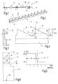
Figure 1 the process sequence for the induction hardening of a wire of an all-steel set according to the invention, in a schematic block diagram. -
Figure 2 the wire for producing an all-steel set, in a schematic perspective view. -
Figure 3 the wireFigure 2 , in a cross-sectional view. -
Figure 4 the wireFigure 3 , in a partial side view. -
Figure 5 the hardness curve of a tooth of the wireFigures 3 to 4 and -
Figure 6 a partial cross-sectional view of the wire is similarFigure 3 with illustration of the hardness transition zone.
In
Die Vorrichtung 10 umfasst unter anderem eine Stanzstation 13, die dazu dient, an dem Profildraht 12 Ausnehmungen 14 anzubringen (
Der Stanzstation 13 ist eine Heizstation, z.B. in Form eines ersten Induktors 16 nachgeordnet, der zur induktiven Erwärmung des Drahts 11 mit dient. Der erste Induktor 16 erzeugt dabei ein Feld, das mindestens den Fußabschnitt 17 des Drahts 11, gegebenenfalls aber auch seine Zähne 15 miterfasst. Der erste Induktor 16 arbeitet mit der ersten Frequenz f1 zwischen 100 kHz und 5 MHz, vorzugsweise zwischen 500 kHz und 2 MHz, im vorliegenden Ausführungsbeispiel mit 1 MHz. Vorzugsweise wird der Draht 11 dabei insbesondere im Bereich seines Fußabschnitts 17 auf eine erste Temperatur t1 von vorzugsweise mehr als 300°C erwärmt. Im vorliegenden Ausführungsbeispiel beträgt die Temperatur t1 700°C bis 750°C. Sie ist vorzugsweise so festgelegt, dass beim späteren Abschrecken keine Härtung des Fußbereichs 17 erfolgt.The punching
In einigem Abstand (z.B. wenige Dezimeter) zu dem ersten Induktor 16 ist ein zweiter Induktor 18 vorgesehen, der mit einer deutlich höheren Frequenz f2 arbeitet. Diese ist wenigstens 5, vorzugsweise wenigstens 10 und am meisten bevorzugt wenigstens 20 mal so hoch wie die erste Frequenz f1. Beispielsweise beträgt die zweite Frequenz f2 20 MHz bis 30 MHz, vorzugsweise 27 MHz. Der zweite Induktor 18 ist dabei vorzugsweise so ausgebildet, dass er lediglich die Zähne 15 oder einen Abschnitt jedes Zahns 15 erfasst. Zwischen den Induktoren 16 und 18 ist keine aktive Abkühlung des Drahts 11 vorgesehen. Vielmehr durchläuft der Draht 11 den Abstand in weniger als 2, vorzugsweise weniger als 1 s.At some distance (e.g. a few decimeters) from the
Nach Durchlauf durch die Induktoren 16 und 18 erreicht der Draht 11 die Abschreckstation 22 in heißem Zustand. Dabei hat der Fußabschnitt 17 eine unterhalb des Austenitisierungstemperaturbereichs tA liegende Temperatur t1, während der Abschnitt 19 jedes Zahns 15 eine im Austenitisierungstemperaturbereich tA liegende Temperatur t2 aufweist. Das Temperaturgefälle von dem Abschnitt 19 zu dem Fußabschnitt 17 bewirkt, dass der Draht 11 beim Einlaufen in die Abschreckstation 22 insbesondere an dem Abschnitt 19 gleichmäßig härtet, der Draht 11 im Übrigen jedoch ungehärtet bleibt.After passing through the
Wie aus
Von dem im Querschnitt typischerweise rechteckigen Fußabschnitt 17 erstreckt sich der Wandabschnitt 23 weg, der einen dreieckigen oder, wie dargestellt, trapezförmigen Querschnitt haben kann. Nach Durchlauf durch den zweiten Induktor 18 ist an dem Draht 11 eine Temperaturübergangszone 24 ausgebildet, in der die Temperatur von der weiten hohen Temperatur t2 (zum Beispiel 950°C) auf die erste niedrige Temperatur t1 (z.B. 550°C) abfällt, die unterhalb der Temperaturübergangszone 24 an dem verbleibenden Abschnitt der Wand 23 und dem Fußabschnitt 17 zu messen ist. Entsprechend ergibt sich beim Abschrecken nach Durchlauf durch die Abschreckstation 22 in dem Draht 11 der in
Bei dem erfindungsgemäßen Verfahren durchläuft ein mit Zähnen 15 versehener Draht 11 nacheinander einen ersten Induktor 16 und einen zweiten Induktor 18. Die Induktoren 16, 18 arbeiten mit unterschiedlichen Frequenzen f1, f2 und erzeugen unterschiedliche Temperaturen t1, t2. Der erste Induktor 16 erwärmt insbesondere die nicht zu härtenden Fußabschnitte 17 auf eine hohe Temperatur t1 unterhalb des Austenitisierungstemperaturbereichs tA. Der zweite Induktor 18 erwärmt die Zähne 15 auf eine noch höhere zweite im Austenitisierungstemperaturbereich tA liegende Temperatur t2. Beim Abschrecken ergeben sich definiert gehärtete Zähne gleichbleibend hoher Qualität.In the method according to the invention, a
Zur Verbesserung der Eigenschaften des Drahts 11, insbesondere zum Abbau von Spannungen, kann der Draht einen dritten Induktor 29 durchlaufen. Dieser arbeitet mit einer dritten Frequenz f3, die zwischen 500 kHz und 5 MHz liegen kann und vorzugsweise zwischen 1 MHz und 2 MHz liegt. Die Frequenz f3 kann mit der ersten Frequenz f1 übereinstimmen. Die durch den dritten Induktor 29 erzeugte Temperatur t3 ist eine Anlasstemperatur von z.B. wenigen hundert Grad Celsius.To improve the properties of the
Außerdem kann der Draht 11 vor oder nach dem Anlassen durch eine Entgratungsstation geführt werden. In dieser können Stanzgrate, die beim Ausstanzen der Ausnehmungen 14 entstanden sein können, z.B. durch Bürsten beseitigt werden, die z.B. auf nur eine Flachseite der Zähne 15 einwirken.In addition, the
Bei dem erfindungsgemäßen Verfahren durchläuft ein mit Zähnen 15 versehener Draht 11 nacheinander einen ersten Induktor 16 und einen zweiten Induktor 18. Die Induktoren 16,18 arbeiten mit unterschiedlichen Frequenzen und erzeugen unterschiedliche Temperaturen. Der erste Induktor 16 erwärmt insbesondere den nicht zu härtenden Fußabschnitt 17 auf eine hohe Temperatur unterhalb des Austenitisierungstemperaturbereichs. Der zweite Induktor 18 erwärmt die Zähne 15 auf eine noch höhere zweite innerhalb des Austenitisierungstemperaturbereichs liegende Temperatur. Beim Abschrecken ergeben sich definiert gehärtete Zähne gleichbleibend hoher Qualität.In the method according to the invention, a
- 1010
- Vorrichtungcontraption
- 1111
- Drahtwire
- 1212
- Profildrahtprofile wire
- 1313
- Stanzstationpunching station
- 1414
- Ausnehmungenrecesses
- 1515
- ZähneTeeth
- H15H15
- ZahnhöheTooth height
- 1616
- Erster Induktor oder sonstige WärmequelleFirst inductor or other heat source
- 1717
- Fußabschnittfoot section
- t1t1
- Erste TemperaturFirst temperature
- f1f1
- Erste FrequenzFirst frequency
- 1818
- Zweiter InduktorSecond inductor
- t2t2
- Zweite TemperaturSecond temperature
- f2f2
- Zweite FrequenzSecond frequency
- 1919
-
Abschnitt des Zahns 15Section of
tooth 15 - 2020
-
Spitze des Zahns 15Tip of
tooth 15 - 2121
- Zahngrundbase of the tooth
- H19H19
-
Höhe des Abschnitts 19Height of
section 19 - 2222
- Abschreckstationquenching station
- tAtA
- AustenitisierungstemperaturbereichAustenitizing temperature range
- D17D17
-
Dicke des Fußabschnitts 17Thickness of the
foot section 17 - D15D15
-
Dicke des Zahns 15
Tooth thickness 15 - 2323
- WandabschnittWall section
- 2424
- TemperaturübergangszoneTemperature transition zone
- H24H24
- Höhe der ZoneHeight of the zone
- AA
- AbstandDistance
- 25,26,27,2825,26,27,28
- Linienlines
- f3f3
- Dritte FrequenzThird frequency
- t3t3
- Dritte TemperaturThird temperature
- 2929
- Dritter Induktor / sonstige WärmequelleThird inductor/other heat source
- 3030
- Zahnrückenback of teeth
Claims (15)
- An all-steel card clothing for carding machines comprising a wire (11) defining a longitudinal direction (L), said wire (11) having a base section (17) and a wall section (23) with teeth (15) having a tooth height (H15), said wall section having at least one hardened section (19) and extending away from the base section (17),wherein the base section (17) has a greater thickness (D17) than the wall section (23),whereinthe wall section (23) has a boundary following a straight line in the form of a transition zone (24) extending parallel to the longitudinal direction (L), in which transition zone the increased hardness beginscharacterized inthat the transition zone (24) is delimited from the hardened section (19) and the unhardened region transversely through the wall section (23) along curved lines (27, 28).
- All-steel card clothing according to claim 1, characterized in that the height (H24) amounts to at most 20% of the tooth height (H15).
- All-steel card clothing according to claim 1 or 2, characterized in that the transition zone (24) is formed within the teeth.
- All-steel card clothing according to previous claims, characterized in that a tooth gullet (21) is formed between the teeth (15), in which case the distance of the transition zone (24) from the tooth tip (20) amounts to preferably at least 70% of the tooth height (H15).
- All-steel card clothing according to Claim 1 to 3, characterized in that the wall section (23) has teeth (15) between which one tooth gullet (21), respectively, is formed, and that the transition zone (24) contacts or contains the tooth gullet (21), or extends below said tooth gullet.
- All-steel card clothing according to one of the previous claims, characterized in that the wall section (23) has a cross-section that is formed being tapered away from the base section (17) in a trapezoidal or triangular manner.
- All-steel card clothing according to one of the previous claims, characterized in that each tooth (15) has a tooth tip (20) and a straight tooth back (30), said tooth back extending up to the tooth tip (20).
- All-steel card clothing according to one of the previous claims, characterized in that it is largely metallic bright and free of scales, respectively, in which case said card clothing is free of traces of a chemical burr removal or subsequent processing, as well as free of traces of any mechanical finishing on both sides.
- Method for the production of an all-steel card clothing for carding machines, wherein the method comprises the following steps ofproviding a wire (11) having a base section (17) and a wall section (23) that extends away from the base section (17) and has a lower thickness (D15) than said base section,applying recesses (14) in the wall section (23) of the raw material wire (12) in order to form teeth (15), between which one tooth gullet (21), respectively, is formed,in feed-through mode, heating of at least the base section (17) of the wire (11) by means of at least one first inductor (16) at a first frequency (f1) to a first temperature (t1),in feed-through mode, at least section by section induction heating of the wall section (23) of the wire (11), said wire having been preheated at least on the base section (17), by means of at least one second inductor (18) at a specific second frequency (f2) to a second temperature (t2), wherein the second temperature (t2) is higher than the first temperature (t1),in feed-through mode, quenching of at least the wall section (23) of the wire (11) with a cooling medium.
- Method according to Claim 9, characterized in that the first temperature (f1) is below an austenitizing temperature range (tA) and that the second temperature is within the austenitizing temperature range (tA).
- Method according to the Claim 9 or 10, characterized in that the second frequency (f2) is higher than the first frequency (f1).
- Method according to Claim 11, characterized in that the first frequency (f1) is at most 5 MHz, preferably at most 3 MHz, and that the second frequency is at least 10 MHz, preferably at least 15 MHz.
- Method according to one of the Claim 11 or 12, characterized in that, after quenching, the wire (11) is passed through a third inductor (29) that is operated at a third frequency (f3) that is lower than the second frequency (f2) in order to heat the wire to a third temperature that is at least lower than the second temperature (t2) and preferably lower than the first temperature (t1).
- Method according to one of the Claims 11 to 13, characterized in that at least the induction heating at the second frequency (f2) to the second temperature (t2) takes place under protective gas.
- Method according to one of the Claims 9 to 14, characterized in that the wire (11) is brushed at least on one lateral surface.
Priority Applications (1)
| Application Number | Priority Date | Filing Date | Title |
|---|---|---|---|
| EP19195680.4A EP3597802B1 (en) | 2014-05-09 | 2014-05-09 | Card clothing formed from metal strips and its manufacturing process |
Applications Claiming Priority (2)
| Application Number | Priority Date | Filing Date | Title |
|---|---|---|---|
| EP14167767.4A EP2942425B1 (en) | 2014-05-09 | 2014-05-09 | Card clothing formed from metal strips |
| EP19195680.4A EP3597802B1 (en) | 2014-05-09 | 2014-05-09 | Card clothing formed from metal strips and its manufacturing process |
Related Parent Applications (2)
| Application Number | Title | Priority Date | Filing Date |
|---|---|---|---|
| EP14167767.4A Division EP2942425B1 (en) | 2014-05-09 | 2014-05-09 | Card clothing formed from metal strips |
| EP14167767.4A Division-Into EP2942425B1 (en) | 2014-05-09 | 2014-05-09 | Card clothing formed from metal strips |
Publications (3)
| Publication Number | Publication Date |
|---|---|
| EP3597802A1 EP3597802A1 (en) | 2020-01-22 |
| EP3597802B1 true EP3597802B1 (en) | 2023-12-20 |
| EP3597802C0 EP3597802C0 (en) | 2023-12-20 |
Family
ID=50685790
Family Applications (2)
| Application Number | Title | Priority Date | Filing Date |
|---|---|---|---|
| EP14167767.4A Active EP2942425B1 (en) | 2014-05-09 | 2014-05-09 | Card clothing formed from metal strips |
| EP19195680.4A Active EP3597802B1 (en) | 2014-05-09 | 2014-05-09 | Card clothing formed from metal strips and its manufacturing process |
Family Applications Before (1)
| Application Number | Title | Priority Date | Filing Date |
|---|---|---|---|
| EP14167767.4A Active EP2942425B1 (en) | 2014-05-09 | 2014-05-09 | Card clothing formed from metal strips |
Country Status (8)
| Country | Link |
|---|---|
| US (1) | US11414792B2 (en) |
| EP (2) | EP2942425B1 (en) |
| JP (2) | JP6794263B2 (en) |
| KR (1) | KR102455649B1 (en) |
| CN (3) | CN106661646B (en) |
| BR (1) | BR112016025607B1 (en) |
| RU (1) | RU2682530C2 (en) |
| WO (1) | WO2015169797A1 (en) |
Families Citing this family (2)
| Publication number | Priority date | Publication date | Assignee | Title |
|---|---|---|---|---|
| EP2942425B1 (en) * | 2014-05-09 | 2019-11-20 | Groz-Beckert KG | Card clothing formed from metal strips |
| DE102021102373A1 (en) | 2021-02-02 | 2022-08-04 | Groz-Beckert Kommanditgesellschaft | Process for laser hardening a clothing wire |
Citations (2)
| Publication number | Priority date | Publication date | Assignee | Title |
|---|---|---|---|---|
| DE10238065A1 (en) * | 2001-10-02 | 2003-04-17 | Holding Fuer Industriebeteilig | Roller to break down sliver into separate fibers, for a rotor spinning machine, has a toothed clothing of radially projecting teeth in rows separated by grooves at an angle to the peripheral direction |
| CN1594606A (en) * | 2003-09-12 | 2005-03-16 | 中国科学院力学研究所 | System and method for metal card clothing quenching treatment adopting YAG laser |
Family Cites Families (31)
| Publication number | Priority date | Publication date | Assignee | Title |
|---|---|---|---|---|
| DE10542C (en) | J. ENGEL in Berlin, Hochstrafse 421 | Removable roasting oven attachment for cooking stoves | ||
| US2326674A (en) * | 1940-07-26 | 1943-08-10 | Simonds Saw And Steel Co | Induction hardening of saw teeth |
| DE2332685A1 (en) | 1973-06-27 | 1975-01-23 | Stromeyer Albrecht Dr | Wire forming for saw-tooth steel wires - features radially guided periodically acting tools such as stamping or notching blades |
| US4109127A (en) * | 1973-07-25 | 1978-08-22 | Frank Frungel | Apparatus and method for case hardening steel tools by application of heating pulses |
| DE2904841A1 (en) | 1979-02-09 | 1980-08-21 | Fritz Stahlecker | Fibre loosening roller wire - has saw teeth with different hardness zones |
| JPS5641320A (en) | 1979-09-11 | 1981-04-18 | Kanai Hiroyuki | Continuous annealing method for metallic card cloth |
| JPH0615726B2 (en) | 1985-01-07 | 1994-03-02 | 金井 宏之 | Metallic wire for spinning machine and method for manufacturing the same |
| US5096506A (en) | 1988-11-18 | 1992-03-17 | Hollingsworth John D | Method for making card clothing |
| US4964195A (en) * | 1988-11-18 | 1990-10-23 | Hollingsworth John D | Metallic card clothing |
| JP2909774B2 (en) * | 1990-12-28 | 1999-06-23 | 金井 宏之 | Heat treatment method of metallic wire for spinning machine |
| JPH07118935A (en) * | 1993-10-29 | 1995-05-09 | Kanai Hiroyuki | Metallic wire for spinning machine |
| DE19940845C1 (en) | 1999-08-27 | 2000-12-21 | Graf & Co Ag | Fine wire production process, especially for producing steel wires for textile fiber carding, uses the same furnace and-or cooling system for pre-annealing and drawn wire hardening treatment |
| DE10007567C2 (en) | 2000-02-18 | 2003-08-07 | Graf & Co Ag | Method and device for producing a wire |
| DE10106673A1 (en) | 2001-02-14 | 2002-08-29 | Rieter Ingolstadt Spinnerei | A method for producing an opening roller of an open-end spinning device and an opening roller produced using such a method |
| JP2004244748A (en) * | 2003-02-13 | 2004-09-02 | Kanai Hiroaki | Metallic wire for carding machine |
| JP4241120B2 (en) | 2003-03-24 | 2009-03-18 | 富士ゼロックス株式会社 | Information management apparatus, information management method, and information management program |
| RU2359431C2 (en) * | 2004-04-21 | 2009-06-20 | Индактохит, Инк. | Thermal processing objects through multi-frequency induction heating |
| DE102005025627B3 (en) * | 2005-06-03 | 2006-10-05 | Graf + Cie Ag | Production of sawtooth wire clothing for textile carding comprises cutting saw teeth in wire and hardening it by heating in protective atmosphere to austenite-forming temperature and rapidly cooling it, wire then being annealed |
| DE102006030418B4 (en) | 2006-06-29 | 2021-06-10 | Trützschler GmbH & Co Kommanditgesellschaft | Saw-tooth wire for the production of a saw-tooth all-steel clothing for a roller or a carding element of a spinning machine |
| US7735201B1 (en) * | 2008-08-06 | 2010-06-15 | Nv Bekaert Sa | Multiple wire card wiring, carding cylinder, and method of making such |
| EP2567010B1 (en) | 2010-05-04 | 2014-09-24 | NV Bekaert SA | Wire profile for card clothing |
| WO2012019841A1 (en) * | 2010-08-09 | 2012-02-16 | Nv Bekaert Sa | Wire profile for card clothing |
| WO2013037711A1 (en) * | 2011-09-15 | 2013-03-21 | Nv Bekaert Sa | Card wire with improved tooth shape |
| US9404201B2 (en) * | 2011-11-15 | 2016-08-02 | Groz-Beckert Kg | Metallic card wire |
| EP2918710A1 (en) * | 2014-03-12 | 2015-09-16 | Groz-Beckert KG | Card clothing wire and method for the preparation of staple fibre non-woven fabrics |
| EP2942425B1 (en) | 2014-05-09 | 2019-11-20 | Groz-Beckert KG | Card clothing formed from metal strips |
| EP2944712B1 (en) * | 2014-05-16 | 2018-09-05 | Groz-Beckert KG | Metallic card wire for card clothing |
| CA2960321C (en) * | 2014-09-12 | 2022-08-16 | Aleris Aluminum Duffel Bvba | Method of annealing aluminium alloy sheet material |
| CH711166A1 (en) * | 2015-06-05 | 2016-12-15 | Graf + Cie Ag | Stainless steel. |
| CH713140A1 (en) * | 2016-11-16 | 2018-05-31 | Graf Cie Ag | Clothing wire. |
| JP7118935B2 (en) | 2019-09-10 | 2022-08-16 | 矢崎総業株式会社 | Ground fault detector |
-
2014
- 2014-05-09 EP EP14167767.4A patent/EP2942425B1/en active Active
- 2014-05-09 EP EP19195680.4A patent/EP3597802B1/en active Active
-
2015
- 2015-05-05 KR KR1020167031055A patent/KR102455649B1/en active IP Right Grant
- 2015-05-05 CN CN201580024128.4A patent/CN106661646B/en active Active
- 2015-05-05 BR BR112016025607-7A patent/BR112016025607B1/en active IP Right Grant
- 2015-05-05 RU RU2016141256A patent/RU2682530C2/en active
- 2015-05-05 JP JP2016567226A patent/JP6794263B2/en active Active
- 2015-05-05 CN CN202011267008.6A patent/CN112553421A/en active Pending
- 2015-05-05 WO PCT/EP2015/059839 patent/WO2015169797A1/en active Application Filing
- 2015-05-05 CN CN202111013753.2A patent/CN113699329A/en active Pending
- 2015-05-05 US US15/309,745 patent/US11414792B2/en active Active
-
2020
- 2020-11-11 JP JP2020188156A patent/JP7537069B2/en active Active
Patent Citations (2)
| Publication number | Priority date | Publication date | Assignee | Title |
|---|---|---|---|---|
| DE10238065A1 (en) * | 2001-10-02 | 2003-04-17 | Holding Fuer Industriebeteilig | Roller to break down sliver into separate fibers, for a rotor spinning machine, has a toothed clothing of radially projecting teeth in rows separated by grooves at an angle to the peripheral direction |
| CN1594606A (en) * | 2003-09-12 | 2005-03-16 | 中国科学院力学研究所 | System and method for metal card clothing quenching treatment adopting YAG laser |
Also Published As
| Publication number | Publication date |
|---|---|
| CN106661646B (en) | 2021-08-17 |
| WO2015169797A1 (en) | 2015-11-12 |
| JP7537069B2 (en) | 2024-08-21 |
| BR112016025607A2 (en) | 2017-08-15 |
| JP2017519104A (en) | 2017-07-13 |
| CN112553421A (en) | 2021-03-26 |
| CN106661646A (en) | 2017-05-10 |
| RU2016141256A (en) | 2018-06-09 |
| EP2942425A1 (en) | 2015-11-11 |
| US11414792B2 (en) | 2022-08-16 |
| EP3597802C0 (en) | 2023-12-20 |
| RU2682530C2 (en) | 2019-03-19 |
| US20170145600A1 (en) | 2017-05-25 |
| JP6794263B2 (en) | 2020-12-02 |
| KR102455649B1 (en) | 2022-10-19 |
| RU2016141256A3 (en) | 2018-08-31 |
| CN113699329A (en) | 2021-11-26 |
| JP2021038462A (en) | 2021-03-11 |
| KR20160149212A (en) | 2016-12-27 |
| EP2942425B1 (en) | 2019-11-20 |
| EP3597802A1 (en) | 2020-01-22 |
| BR112016025607B1 (en) | 2022-03-15 |
Similar Documents
| Publication | Publication Date | Title |
|---|---|---|
| DE112009000750B4 (en) | Steel article, method of making the steel article and apparatus for making a steel article | |
| EP2028281B1 (en) | Heat treatment of flexibly rolled sheet | |
| EP2014777B1 (en) | Method and device for thermal treatment of metal sheet | |
| EP2907881A2 (en) | Thermoforming line and method for the preparation of thermoformed sheet metal products | |
| WO2016012442A1 (en) | Method for heating up steel sheets and device for carrying out the method | |
| EP2883967B1 (en) | Method and device for post-treatment of a hardened metallic moulded part by means of electrical resistance heating | |
| DE102014106574B4 (en) | Metallic wire | |
| EP3597802B1 (en) | Card clothing formed from metal strips and its manufacturing process | |
| DE102011007590B4 (en) | Method and device for sliding bending | |
| WO2016177733A1 (en) | Method and device for inductive progressive hardening by means of controllable preheating and an inductor configured for preheating and hardening | |
| DE102006015669B3 (en) | Method for converting the metallic structure of a plasticizing screw comprises impinging the wear region with an alternating current, producing resistance heat to raise the wear region to a hardening temperature and cooling the region | |
| EP2371983A1 (en) | Method for heat treating a moulded component and moulded component produced using the method | |
| EP0442864B1 (en) | Method and arrangement for rolling of rods and wires | |
| CH711031B1 (en) | Method for producing guide rails for a linear roller bearing. | |
| DE102019202000A1 (en) | Device and method for inductive feed hardening of roller bearing raceways | |
| AT513628B1 (en) | Method and apparatus for heat treating long products | |
| AT514367B1 (en) | Hollow rack and method of making the same | |
| CH712700A2 (en) | Method for producing guide rails for a linear roller bearing. | |
| EP4261295A1 (en) | Method for producing a blade | |
| WO2013030017A1 (en) | Device for hardening a surface having rib-like or tooth-like elements | |
| DE3234299C2 (en) | Method for surface hardening of workpieces and device for carrying out the method | |
| EP3985133A2 (en) | Method for making a steel plate and temperature control station | |
| DE102015122390A1 (en) | Process for the conductive heating of a flat metallic component | |
| DE102018219930A1 (en) | Hot-forming and press-hardening tool and method for producing a molded component with at least two structural areas of different ductility | |
| DE102017004935A1 (en) | Heating device for generating Joule'scher heat in the heating of preferably thin-walled sheet metal parts by means of medium-frequency power |
Legal Events
| Date | Code | Title | Description |
|---|---|---|---|
| PUAI | Public reference made under article 153(3) epc to a published international application that has entered the european phase |
Free format text: ORIGINAL CODE: 0009012 |
|
| STAA | Information on the status of an ep patent application or granted ep patent |
Free format text: STATUS: REQUEST FOR EXAMINATION WAS MADE |
|
| 17P | Request for examination filed |
Effective date: 20190905 |
|
| AC | Divisional application: reference to earlier application |
Ref document number: 2942425 Country of ref document: EP Kind code of ref document: P |
|
| AK | Designated contracting states |
Kind code of ref document: A1 Designated state(s): AL AT BE BG CH CY CZ DE DK EE ES FI FR GB GR HR HU IE IS IT LI LT LU LV MC MK MT NL NO PL PT RO RS SE SI SK SM TR |
|
| STAA | Information on the status of an ep patent application or granted ep patent |
Free format text: STATUS: EXAMINATION IS IN PROGRESS |
|
| 17Q | First examination report despatched |
Effective date: 20220603 |
|
| RIC1 | Information provided on ipc code assigned before grant |
Ipc: C21D 9/24 20060101ALN20230420BHEP Ipc: C21D 1/42 20060101ALI20230420BHEP Ipc: C21D 1/10 20060101ALI20230420BHEP Ipc: C21D 9/26 20060101ALI20230420BHEP Ipc: D01G 15/88 20060101AFI20230420BHEP |
|
| GRAP | Despatch of communication of intention to grant a patent |
Free format text: ORIGINAL CODE: EPIDOSNIGR1 |
|
| STAA | Information on the status of an ep patent application or granted ep patent |
Free format text: STATUS: GRANT OF PATENT IS INTENDED |
|
| RIC1 | Information provided on ipc code assigned before grant |
Ipc: C21D 9/24 20060101ALN20230627BHEP Ipc: C21D 1/42 20060101ALI20230627BHEP Ipc: C21D 1/10 20060101ALI20230627BHEP Ipc: C21D 9/26 20060101ALI20230627BHEP Ipc: D01G 15/88 20060101AFI20230627BHEP |
|
| INTG | Intention to grant announced |
Effective date: 20230713 |
|
| GRAS | Grant fee paid |
Free format text: ORIGINAL CODE: EPIDOSNIGR3 |
|
| GRAA | (expected) grant |
Free format text: ORIGINAL CODE: 0009210 |
|
| STAA | Information on the status of an ep patent application or granted ep patent |
Free format text: STATUS: THE PATENT HAS BEEN GRANTED |
|
| AC | Divisional application: reference to earlier application |
Ref document number: 2942425 Country of ref document: EP Kind code of ref document: P |
|
| AK | Designated contracting states |
Kind code of ref document: B1 Designated state(s): AL AT BE BG CH CY CZ DE DK EE ES FI FR GB GR HR HU IE IS IT LI LT LU LV MC MK MT NL NO PL PT RO RS SE SI SK SM TR |
|
| REG | Reference to a national code |
Ref country code: GB Ref legal event code: FG4D Free format text: NOT ENGLISH |
|
| REG | Reference to a national code |
Ref country code: CH Ref legal event code: EP |
|
| REG | Reference to a national code |
Ref country code: DE Ref legal event code: R096 Ref document number: 502014016745 Country of ref document: DE |
|
| REG | Reference to a national code |
Ref country code: IE Ref legal event code: FG4D Free format text: LANGUAGE OF EP DOCUMENT: GERMAN |
|
| U01 | Request for unitary effect filed |
Effective date: 20231222 |
|
| U07 | Unitary effect registered |
Designated state(s): AT BE BG DE DK EE FI FR IT LT LU LV MT NL PT SE SI Effective date: 20240109 |
|
| PG25 | Lapsed in a contracting state [announced via postgrant information from national office to epo] |
Ref country code: GR Free format text: LAPSE BECAUSE OF FAILURE TO SUBMIT A TRANSLATION OF THE DESCRIPTION OR TO PAY THE FEE WITHIN THE PRESCRIBED TIME-LIMIT Effective date: 20240321 |
|
| PG25 | Lapsed in a contracting state [announced via postgrant information from national office to epo] |
Ref country code: ES Free format text: LAPSE BECAUSE OF FAILURE TO SUBMIT A TRANSLATION OF THE DESCRIPTION OR TO PAY THE FEE WITHIN THE PRESCRIBED TIME-LIMIT Effective date: 20231220 |
|
| PG25 | Lapsed in a contracting state [announced via postgrant information from national office to epo] |
Ref country code: GR Free format text: LAPSE BECAUSE OF FAILURE TO SUBMIT A TRANSLATION OF THE DESCRIPTION OR TO PAY THE FEE WITHIN THE PRESCRIBED TIME-LIMIT Effective date: 20240321 Ref country code: ES Free format text: LAPSE BECAUSE OF FAILURE TO SUBMIT A TRANSLATION OF THE DESCRIPTION OR TO PAY THE FEE WITHIN THE PRESCRIBED TIME-LIMIT Effective date: 20231220 |
|
| PGFP | Annual fee paid to national office [announced via postgrant information from national office to epo] |
Ref country code: GB Payment date: 20240321 Year of fee payment: 11 |
|
| PG25 | Lapsed in a contracting state [announced via postgrant information from national office to epo] |
Ref country code: RS Free format text: LAPSE BECAUSE OF FAILURE TO SUBMIT A TRANSLATION OF THE DESCRIPTION OR TO PAY THE FEE WITHIN THE PRESCRIBED TIME-LIMIT Effective date: 20231220 Ref country code: NO Free format text: LAPSE BECAUSE OF FAILURE TO SUBMIT A TRANSLATION OF THE DESCRIPTION OR TO PAY THE FEE WITHIN THE PRESCRIBED TIME-LIMIT Effective date: 20240320 Ref country code: HR Free format text: LAPSE BECAUSE OF FAILURE TO SUBMIT A TRANSLATION OF THE DESCRIPTION OR TO PAY THE FEE WITHIN THE PRESCRIBED TIME-LIMIT Effective date: 20231220 |
|
| PG25 | Lapsed in a contracting state [announced via postgrant information from national office to epo] |
Ref country code: IS Free format text: LAPSE BECAUSE OF FAILURE TO SUBMIT A TRANSLATION OF THE DESCRIPTION OR TO PAY THE FEE WITHIN THE PRESCRIBED TIME-LIMIT Effective date: 20240420 |
|
| U20 | Renewal fee paid [unitary effect] |
Year of fee payment: 11 Effective date: 20240531 |
|
| PGFP | Annual fee paid to national office [announced via postgrant information from national office to epo] |
Ref country code: CH Payment date: 20240602 Year of fee payment: 11 |
|
| PG25 | Lapsed in a contracting state [announced via postgrant information from national office to epo] |
Ref country code: CZ Free format text: LAPSE BECAUSE OF FAILURE TO SUBMIT A TRANSLATION OF THE DESCRIPTION OR TO PAY THE FEE WITHIN THE PRESCRIBED TIME-LIMIT Effective date: 20231220 |
|
| PG25 | Lapsed in a contracting state [announced via postgrant information from national office to epo] |
Ref country code: SK Free format text: LAPSE BECAUSE OF FAILURE TO SUBMIT A TRANSLATION OF THE DESCRIPTION OR TO PAY THE FEE WITHIN THE PRESCRIBED TIME-LIMIT Effective date: 20231220 |
|
| PG25 | Lapsed in a contracting state [announced via postgrant information from national office to epo] |
Ref country code: SM Free format text: LAPSE BECAUSE OF FAILURE TO SUBMIT A TRANSLATION OF THE DESCRIPTION OR TO PAY THE FEE WITHIN THE PRESCRIBED TIME-LIMIT Effective date: 20231220 Ref country code: SK Free format text: LAPSE BECAUSE OF FAILURE TO SUBMIT A TRANSLATION OF THE DESCRIPTION OR TO PAY THE FEE WITHIN THE PRESCRIBED TIME-LIMIT Effective date: 20231220 Ref country code: RO Free format text: LAPSE BECAUSE OF FAILURE TO SUBMIT A TRANSLATION OF THE DESCRIPTION OR TO PAY THE FEE WITHIN THE PRESCRIBED TIME-LIMIT Effective date: 20231220 Ref country code: IS Free format text: LAPSE BECAUSE OF FAILURE TO SUBMIT A TRANSLATION OF THE DESCRIPTION OR TO PAY THE FEE WITHIN THE PRESCRIBED TIME-LIMIT Effective date: 20240420 Ref country code: CZ Free format text: LAPSE BECAUSE OF FAILURE TO SUBMIT A TRANSLATION OF THE DESCRIPTION OR TO PAY THE FEE WITHIN THE PRESCRIBED TIME-LIMIT Effective date: 20231220 |
|
| PG25 | Lapsed in a contracting state [announced via postgrant information from national office to epo] |
Ref country code: PL Free format text: LAPSE BECAUSE OF FAILURE TO SUBMIT A TRANSLATION OF THE DESCRIPTION OR TO PAY THE FEE WITHIN THE PRESCRIBED TIME-LIMIT Effective date: 20231220 |
|
| PG25 | Lapsed in a contracting state [announced via postgrant information from national office to epo] |
Ref country code: PL Free format text: LAPSE BECAUSE OF FAILURE TO SUBMIT A TRANSLATION OF THE DESCRIPTION OR TO PAY THE FEE WITHIN THE PRESCRIBED TIME-LIMIT Effective date: 20231220 |
|
| PGFP | Annual fee paid to national office [announced via postgrant information from national office to epo] |
Ref country code: TR Payment date: 20240422 Year of fee payment: 11 |