EP3597489A1 - Kraftfahrzeugsitz mit einem gurtsystem - Google Patents
Kraftfahrzeugsitz mit einem gurtsystem Download PDFInfo
- Publication number
- EP3597489A1 EP3597489A1 EP19159346.6A EP19159346A EP3597489A1 EP 3597489 A1 EP3597489 A1 EP 3597489A1 EP 19159346 A EP19159346 A EP 19159346A EP 3597489 A1 EP3597489 A1 EP 3597489A1
- Authority
- EP
- European Patent Office
- Prior art keywords
- belt
- piece
- tongue
- motor vehicle
- vehicle seat
- Prior art date
- Legal status (The legal status is an assumption and is not a legal conclusion. Google has not performed a legal analysis and makes no representation as to the accuracy of the status listed.)
- Granted
Links
Images


Classifications
-
- B—PERFORMING OPERATIONS; TRANSPORTING
- B60—VEHICLES IN GENERAL
- B60R—VEHICLES, VEHICLE FITTINGS, OR VEHICLE PARTS, NOT OTHERWISE PROVIDED FOR
- B60R22/00—Safety belts or body harnesses in vehicles
- B60R22/02—Semi-passive restraint systems, e.g. systems applied or removed automatically but not both ; Manual restraint systems
- B60R22/023—Three-point seat belt systems comprising two side lower and one side upper anchoring devices
-
- A—HUMAN NECESSITIES
- A61—MEDICAL OR VETERINARY SCIENCE; HYGIENE
- A61G—TRANSPORT, PERSONAL CONVEYANCES, OR ACCOMMODATION SPECIALLY ADAPTED FOR PATIENTS OR DISABLED PERSONS; OPERATING TABLES OR CHAIRS; CHAIRS FOR DENTISTRY; FUNERAL DEVICES
- A61G3/00—Ambulance aspects of vehicles; Vehicles with special provisions for transporting patients or disabled persons, or their personal conveyances, e.g. for facilitating access of, or for loading, wheelchairs
- A61G3/08—Accommodating or securing wheelchairs or stretchers
- A61G3/0808—Accommodating or securing wheelchairs
-
- A—HUMAN NECESSITIES
- A61—MEDICAL OR VETERINARY SCIENCE; HYGIENE
- A61G—TRANSPORT, PERSONAL CONVEYANCES, OR ACCOMMODATION SPECIALLY ADAPTED FOR PATIENTS OR DISABLED PERSONS; OPERATING TABLES OR CHAIRS; CHAIRS FOR DENTISTRY; FUNERAL DEVICES
- A61G2220/00—Adaptations of particular transporting means
- A61G2220/16—Buses
-
- B—PERFORMING OPERATIONS; TRANSPORTING
- B60—VEHICLES IN GENERAL
- B60R—VEHICLES, VEHICLE FITTINGS, OR VEHICLE PARTS, NOT OTHERWISE PROVIDED FOR
- B60R22/00—Safety belts or body harnesses in vehicles
- B60R22/02—Semi-passive restraint systems, e.g. systems applied or removed automatically but not both ; Manual restraint systems
- B60R2022/027—Four-point seat belt systems, e.g. with the two upper points connected together
Definitions
- the present invention relates to a motor vehicle seat with a belt system.
- motor vehicle seats that is to say seats in a motor vehicle, for example in a car or in a bus
- belt systems as restraint systems for occupants of the motor vehicle, in order to reduce the risk of injury, in particular in the event of an accident in the motor vehicle.
- the most widespread are three-point belt systems, wherein a belt tongue on a vertical belt can be inserted into a belt buckle which is arranged fixed to the vehicle, usually at a height between a backrest and a seat on the motor vehicle seat.
- So-called H-belt systems are also known, two vertical belts being provided for an occupant and a horizontal connecting belt being provided at an approximately medium height of the vertical belts.
- a motor vehicle seat with a belt system comprising a first three-point belt system and a second three-point belt system, with the first three-point belt system a first person being able to be buckled onto the motor vehicle seat and with the second three-point belt system simultaneously being different from the first person second person can be buckled on the motor vehicle seat, the first three-point belt system being designed to be connected via a cross-connection to the second three-point belt system in order to form an H-belt, so that alternatively by means of the H-belt a single person instead of the first and second Person is buckled on the motor vehicle seat.
- a belt system for a motor vehicle seat which can also be wide and thus can form a bench, on the one hand comprises two complete three-point belt systems, so that two people can be buckled onto the motor vehicle seat using a three-point belt.
- parts of the three-point belts can be used in order to belt a person instead using a H-belt system, preferably between the sitting positions for which the three-point belts are intended.
- the first belt which comprises a first belt tongue
- the second belt which comprises a second belt tongue
- the motor vehicle seat and the belt system are preferably arranged such that the seat position of the only person when using the belt system as an H-belt is approximately in the middle between the seat positions of the first and second person when using the belt system as two three-point belt systems.
- the first three-point belt system comprises a first upper belt piece and a first lower belt piece, a first belt tongue being arranged between the first upper belt piece and the first lower belt piece, the first three-point belt system comprising a first buckle for receiving the first belt tongue, the second three-point belt system comprises a second upper belt piece and a second lower belt piece, a second belt tongue being arranged between the second upper belt piece and the second lower belt piece, the second three-point belt system comprising a second buckle for receiving the second belt tongue, being between the first upper belt piece and the is arranged a first lower belt piece, a cross connection, the cross connection having a third belt tongue or a third belt buckle and wherein between the second upper belt piece and the second lower belt piece a suitable counter element, that is, a third belt buckle oss or a third belt tongue is arranged.
- a third belt tongue or, alternatively, a third belt buckle is formed on the cross connector, and at the other end, namely on the second belt, the matching counterpart is arranged, namely a third belt buckle or a third belt tongue.
- first, second and third for the belt tongues and belt buckles etc. in this document each mean separate, different components.
- the third counterpart namely a third belt tongue, can also be formed by the second belt tongue.
- the third belt tongue can also be formed by the first belt tongue.
- the designations "upper” and “lower” belt piece need not be distinguishable, different belts. Rather, these belt pieces are usually formed by a common belt and the belt tongues arranged between these belt pieces can be displaced along the respective belts, so that the lengths of the “upper” and “lower” belt pieces can change continuously.
- the cross connection preferably comprises a third belt piece and the third belt tongue or the third belt buckle is formed at one end of the third belt piece.
- a belt roller is preferably arranged at the upper end of the first three-point belt system, in particular the first upper belt piece, and / or a belt roller is arranged at the upper end of the second three-point belt system, in particular the second upper belt piece.
- the first upper belt piece and the first lower belt piece are preferably formed by a common first belt and / or the second upper belt piece and the second lower belt piece are formed by a common second belt.
- the first belt tongue is preferably slidably arranged between the first upper belt piece and the first lower belt piece and / or the second belt tongue is slidably arranged between the second upper belt piece and the second lower belt piece and / or the cross connector, in particular the third belt piece, is slidably between arranged the first upper belt piece and the first lower belt piece.
- the cross connector and the first belt tongue can be formed on a common first carrier element.
- the second belt tongue and the third belt buckle or alternatively the third belt tongue can be formed on a common second carrier element.
- the carrier element can be a fixed component that can be moved on the first or second belt.
- the second belt tongue between the second upper belt piece and the second lower belt piece can be pivoted from a vertical orientation into a horizontal orientation, so that the second belt tongue forms the third belt tongue in the horizontal orientation, the transverse connection being a third belt buckle for receiving the second strap tongue in a horizontal orientation.
- FIG. 1 A motor vehicle seat according to the invention is shown with a belt system.
- the motor vehicle seat has a seat surface 18 that is wide enough so that two passengers can sit on the seat surface 18.
- the motor vehicle seat is thus designed as a bank.
- the seat 18 is in the Fig. 1 in a normal position of use, in which the seat 18 is aligned horizontally.
- the motor vehicle seat 1 is equipped with a belt system, the belt system comprising a first three-point belt system 2 for a first passenger and a second three-point belt system 3 for a second passenger.
- the first three-point belt system 2 comprises a first upper belt piece 4 and a first lower belt piece 5.
- a first belt tongue 6 is arranged between the first upper belt piece 4 and the first lower belt piece 5.
- the first three-point belt system 2 comprises a first buckle 7 for receiving the first belt tongue 6.
- the second three-point belt system 3 comprises a second upper belt piece 8 and a second lower belt piece 9, with a second between the second upper belt piece 8 and the second lower belt piece 9
- Belt tongue 10 is arranged, wherein the second three-point belt system 3 a second buckle 11 includes for receiving the second belt tongue 10.
- the two three-point belt systems 2, 3 are thus completely designed for belting two passengers.
- a belt roller 15 is arranged in each case.
- the first upper belt piece 4 and the first lower belt piece 5 are formed by a common first belt and the second upper belt piece 8 and the second lower belt piece 9 are formed by a common second belt.
- the first belt tongue 6 is slidably arranged on the first belt between the first upper belt piece 4 and the first lower belt piece 5 and the second belt tongue 10 is slidably arranged on the second belt between the second upper belt piece 8 and the second lower belt piece 9.
- a cross connection 12 is arranged between the first upper belt piece 4 and the first lower belt piece 5, the cross connection 12 having a third belt tongue 13 (alternatively a third belt buckle) and a suitable one between the second upper belt piece 8 and the second lower belt piece 9
- a third belt buckle 14 (alternatively a third belt tongue) is arranged.
- the cross-connection 12 comprises a third belt piece and the third belt tongue 13 is formed at one end of the third belt piece.
- the cross connector 12 is slidably arranged on the first belt, between the first upper belt piece 4 and the first lower belt piece 5.
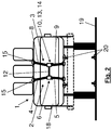
- the third belt tongue 13 of the first three-point belt system 2 can be inserted into the third belt buckle 14 of the second three-point belt system 3 in order to form an H-belt. See also Fig. 2 , A H-belt which is closed in this way allows a passenger to be belted in, in particular in a seating position between the two seating positions of passengers who can be secured with the three-point belt systems 2, 3.
- the first three-point belt system 2 and thus the cross connector 12 is the front view of the 1 to 5 shown on the left, of course the cross connector 12 and thus the "first" three-point belt system 2 could also be located on the right.
- Fastening points 20 for fastening a wheelchair can be arranged on the motor vehicle seat 1 and / or on the vehicle floor 19 in the region of the motor vehicle seat 1.
- the fastening points can be part of a further belt system and can also be formed, for example, by belt buckles and / or belt tongues.
- the attachment of a wheelchair in the area of the motor vehicle seat 1 can be in particular in a state of the motor vehicle seat 1 as shown in FIG Fig. 2 shown is done.
- the motor vehicle seat 1 which in Fig. 2 is shown, the seat surface 18 is pivoted upward and is located vertically, essentially parallel to the backrest of the motor vehicle seat 1.
- the space previously occupied by the seat surface 18, which in FIG Fig. 2 Shown in dashed lines is now free, so that a wheelchair user can drive his wheelchair closer to the backrest and closer to the belt system of the motor vehicle seat 1.
- Wheelchair users are seated on their wheelchair using an H-belt system on vehicle seat 1.
- Fig. 3 finally shows the belt system of a motor vehicle seat 1 according to the invention, together with the fastening points 20, which may be suitable for fastening a wheelchair.
- the position of the details X and Y is shown, which in the Fig. 4 respectively.
- Fig. 5 are shown in more detail.
- Fig. 4 is a partial view of the first belt of the belt system according to detail X of the Fig. 3 ,
- Fig. 5 is a partial view of the second belt of the belt system according to detail Y of Fig. 3 ,
- the cross connector 12 and the first belt tongue 6 are formed on a common first carrier element 16 which is displaceable on the first belt.
- the second belt tongue 10 and the third belt buckle 14 are formed on a common second carrier element 17 which is slidably arranged on the second belt.
- the third belt tongue 13 is located at the end of the cross connector 12, which is formed by a belt piece. This can be inserted in the belt buckle 14 on the second belt, namely in the second carrier element 17, in order to close the H-belt.
- the second belt tongue 10 could also be pivotable between the second upper belt piece 8 and the second lower belt piece 9 from a vertical orientation to a horizontal orientation to form the third belt tongue 13 and the third belt buckle 14 be formed at the end of the cross connector 12, so that the belt tongue 10, 13 can be inserted into the third belt buckle 14 at the end of the cross connection 12 in order to close the H-belt.
Landscapes
- Health & Medical Sciences (AREA)
- Public Health (AREA)
- Life Sciences & Earth Sciences (AREA)
- Animal Behavior & Ethology (AREA)
- General Health & Medical Sciences (AREA)
- Veterinary Medicine (AREA)
- Engineering & Computer Science (AREA)
- Mechanical Engineering (AREA)
- Automotive Seat Belt Assembly (AREA)
- Seats For Vehicles (AREA)
Abstract
Description
- Die vorliegende Erfindung betrifft ein Kraftfahrzeugsitz mit einem Gurtsystem.
- Es ist bekannt, dass Kraftfahrzeugsitze, also Sitze in einem Kraftfahrzeug, beispielsweise in einem PKW oder in einem Bus, mit Gurtsystemen als Rückhaltesysteme für Insassen des Kraftfahrzeugs, zur Reduzierung der Verletzungsgefahr insbesondere bei einem Unfall des Kraftfahrzeuges, ausgestattet sind. Am weitesten verbreitet sind Dreipunktgurtsysteme, wobei eine Gurtzunge an einem vertikalen Gurt in ein Gurtschloss gesteckt werden kann, das fahrzeugfest, üblicherweise auf einer Höhe zwischen einer Lehne und einer Sitzfläche am Kraftfahrzeugsitz, angeordnet ist. Bekannt sind auch sogenannte H-Gurtsysteme, wobei für einen Insassen zwei vertikale Gurte und auf einer etwa mittleren Höhe der vertikalen Gurte ein horizontaler Verbindungsgurt vorgesehen ist.
- Es ist eine Aufgabe der Erfindung, einen Kraftfahrzeugsitz mit einem Gurtsystem anzugeben, wobei das Gurtsystem flexibel ist, so dass das selbe Gurtsystem für eine Belegung des Kraftfahrzeugsitzes durch eine unterschiedliche Anzahl von Passagieren auf dem Kraftfahrzeugsitz vorbereitet ist und/oder für eine Belegung des Kraftfahrzeugsitzes durch eine unterschiedliche Art von Passagieren auf dem Kraftfahrzeugsitz vorbereitet ist, insbesondere durch Passagiere mit Rollstuhl oder ohne Rollstuhl.
- Die Lösung der Aufgabe erfolgt durch einen Kraftfahrzeugsitz mit einem Gurtsystem, wobei das Gurtsystem ein erstes Dreipunktgurtsystem und ein zweites Dreipunktgurtsystem umfasst, wobei mit dem ersten Dreipunktgurtsystem eine erste Person auf dem Kraftfahrzeugsitz anschnallbar ist und wobei mit dem zweiten Dreipunktgurtsystem gleichzeitig eine von der ersten Person verschiedene zweite Person auf dem Kraftfahrzeugsitz anschnallbar ist, wobei das erste Dreipunktgurtsystem dazu ausgebildet ist, über eine Querverbindung mit dem zweiten Dreipunktgurtsystem verbunden zu werden um einen H-Gurt zu bilden, so dass alternativ mittels des H-Gurts eine einzige Person statt der ersten und zweiten Person auf dem Kraftfahrzeugsitz anschnallbar ist.
- Erfindungsgemäß umfasst ein Gurtsystem für einen Kraftfahrzeugsitz, der auch breit ausgebildet sein kann und somit eine Bank bilden kann, einerseits zwei vollständige Dreipunktgurtsysteme, so dass zwei Personen auf dem Kraftfahrzeugsitz mittels Dreipunktgurt angeschnallt werden können. Alternativ können aber Teile der Dreipunktgurte verwendet werden, um stattdessen eine Person - bevorzugt zwischen den Sitz-Positionen für welche die Dreipunktgurte vorgesehen sind - mittels H-Gurtsystem anzugurten. Dazu werden der erste Gurt, welcher eine erste Gurtzunge umfasst und der zweite Gurt, welcher eine zweite Gurtzunge umfasst, als vertikale Teile des H-Gurtsystems verwendet und miteinander über einen Querverbinder, insbesondere ein zusätzliches Gurtstück, verbunden.
- Der Kraftfahrzeugsitz und das Gurtsystem sind bevorzugt so angeordnet, dass die Sitzposition der einzigen Person bei Verwendung des Gurtsystems als H-Gurt etwa mittig zwischen den Sitzpositionen der ersten und zweiten Person bei Verwendung des Gurtsystems als zwei Dreipunktgurtsysteme liegt.
- Vorzugsweise umfasst das erste Dreipunktgurtsystem ein erstes oberes Gurtstück und ein erstes unteres Gurtstück, wobei zwischen dem ersten oberen Gurtstück und dem ersten unteren Gurtstück eine erste Gurtzunge angeordnet ist, wobei das erste Dreipunktgurtsystem ein erstes Gutschloss umfasst zur Aufnahme der ersten Gurtzunge, wobei das zweite Dreipunktgurtsystem ein zweites oberes Gurtstück und ein zweites unteres Gurtstück umfasst, wobei zwischen dem zweiten oberen Gurtstück und dem zweiten unteren Gurtstück eine zweite Gurtzunge angeordnet ist, wobei das zweite Dreipunktgurtsystem ein zweites Gutschloss umfasst zur Aufnahme der zweiten Gurtzunge, wobei zwischen dem ersten oberen Gurtstück und dem ersten unteren Gurtstück eine Querverbindung angeordnet ist, wobei die Querverbindung eine dritte Gurtzunge oder ein drittes Gurtschloss aufweist und wobei zwischen dem zweiten oberen Gurtstück und dem zweiten unteren Gurtstück ein passendes Gegenelement, also ein drittes Gurtschloss oder eine dritte Gurtzunge, angeordnet ist.
- Am Querverbinder ist dazu entweder eine dritte Gurtzunge, oder alternativ ein drittes Gurtschloss ausgebildet und am anderen Ende, nämlich am zweiten Gurt, ist das passende Gegenstück angeordnet, nämlich ein drittes Gurtschloss oder eine dritte Gurtzunge.
- Allgemein bedeuten dabei die Bezeichnungen "erstes", "zweites" und "drittes" für die Gurtzungen und Gurtschlösser etc. in dieser Schrift jeweils separate, voneinander verschiedene Bauteile. Das dritte Gegenstück, nämlich eine dritte Gurtzunge, kann jedoch auch von der zweiten Gurtzunge gebildet werden. Wenn die erste Gurtzunge am Querverbinder befestigt ist, kann die dritte Gurtzunge auch durch die erste Gurtzunge gebildet sein.
- Bei den Bezeichnungen "oberes" und "unteres" Gurtstück muss es sich nicht um unterscheidbare, voneinander verschiedene Gurte handeln. Vielmehr werden diese Gurtstücke üblicherweise von einem gemeinsamen Gurt gebildet und sind die zwischen diesen Gurtstücken angeordneten Gurtzungen entlang der jeweiligen Gurte verschiebbar, so dass sich die Längen der "oberen" und "unteren" Gurtstücke laufend verändern können.
- Vorzugsweise umfasst die Querverbindung ein drittes Gurtstück und ist die dritte Gurtzunge oder das dritte Gurtschloss an einem Ende des dritten Gurtstücks ausgebildet.
- Bevorzugt ist am oberen Ende des ersten Dreipunktgurtsystems, insbesondere des ersten oberen Gurtstücks, ein Gurtroller angeordnet und/oder ist am oberen Ende des zweiten Dreipunktgurtsystems, insbesondere des zweiten oberen Gurtstücks, ein Gurtroller angeordnet.
- Bevorzugt sind das erste obere Gurtstück und das erste untere Gurtstück durch einen gemeinsamen ersten Gurt gebildet und /oder das zweite obere Gurtstück und das zweite untere Gurtstück durch einen gemeinsamen zweiten Gurt gebildet.
- Bevorzugt ist die erste Gurtzunge verschiebbar zwischen dem ersten oberen Gurtstück und dem ersten unteren Gurtstück angeordnet und/oder ist die zweite Gurtzunge verschiebbar zwischen dem zweiten oberen Gurtstück und dem zweiten unteren Gurtstück angeordnet und/oder ist der Querverbinder, insbesondere das dritte Gurtstück, verschiebbar zwischen dem ersten oberen Gurtstück und dem ersten unteren Gurtstück angeordnet.
- Der Querverbinder und die erste Gurtzunge können an einem gemeinsamen ersten Trägerelement ausgebildet sein. Die zweite Gurtzunge und das dritte Gurtschloss oder alternativ die dritte Gurtzunge können an einem gemeinsamen zweiten Trägerelement ausgebildet sein. Das Trägerelement kann ein am ersten bzw. zweiten Gurt verschiebbares festes Bauteil sein.
- Gemäß einer Ausführungsform ist die zweite Gurtzunge zwischen dem zweiten oberen Gurtstück und dem zweiten unteren Gurtstück von einer vertikalen Ausrichtung in eine horizontale Ausrichtung schwenkbar, so dass die zweite Gurtzunge in der horizontalen Ausrichtung die dritte Gurtzunge bildet, wobei die Querverbindung ein drittes Gurtschloss zur Aufnahme der zweiten Gurtzunge in horizontaler Ausrichtung aufweist.
- Die Erfindung wird im Folgenden beispielhaft unter Bezugnahme auf die Zeichnungen beschrieben.
- Fig. 1
- ist eine schematische Darstellung eines erfindungsgemäßen Kraftfahrzeugsitzes mit einem Gurtsystem von vorne in einem ersten Zustand.
- Fig. 2
- ist eine schematische Darstellung eines erfindungsgemäßen Kraftfahrzeugsitzes mit einem Gurtsystem gemäß
Fig. 1 in einem zweiten Zustand. - Fig. 3
- ist eine schematische Darstellung des Gurtsystems eines erfindungsgemäßen Kraftfahrzeugsitzes.
- Fig. 4
- ist eine Teildarstellung des ersten Gurtes des Gurtsystems gemäß Detail X der
Fig. 3 . - Fig. 5
- ist eine Teildarstellung des zweiten Gurtes des Gurtsystems gemäß Detail Y der
Fig. 3 . - In
Fig. 1 ist ein erfindungsgemäßer Kraftfahrzeugsitz mit einem Gurtsystem dargestellt. Der Kraftfahrzeugsitz weist eine Sitzfläche 18 auf, die breit genug ist, so dass zwei Passagiere auf der Sitzfläche 18 sitzen können. Der Kraftfahrzeugsitz ist somit als Bank ausgebildet. Die Sitzfläche 18 befindet sich in derFig. 1 in einer üblichen Gebrauchsstellung, in der die Sitzfläche 18 horizontal ausgerichtet ist. - Der Kraftfahrzeugsitz 1 ist mit einem Gurtsystem ausgestattet, wobei das Gurtsystem ein erstes Dreipunktgurtsystem 2 für einen ersten Passagier und ein zweites Dreipunktgurtsystem 3 für einen zweiten Passagier umfasst. Das erste Dreipunktgurtsystem 2 umfasst ein erstes oberes Gurtstück 4 und ein erstes unteres Gurtstück 5. Zwischen dem ersten oberen Gurtstück 4 und dem ersten unteren Gurtstück 5 ist eine erste Gurtzunge 6 angeordnet. Das erste Dreipunktgurtsystem 2 umfasst ein erstes Gutschloss 7 zur Aufnahme der ersten Gurtzunge 6. Analog dazu umfasst das zweite Dreipunktgurtsystem 3 ein zweites oberes Gurtstück 8 und ein zweites unteres Gurtstück 9, wobei zwischen dem zweiten oberen Gurtstück 8 und dem zweiten unteren Gurtstück 9 eine zweite Gurtzunge 10 angeordnet ist, wobei das zweite Dreipunktgurtsystem 3 ein zweites Gutschloss 11 umfasst zur Aufnahme der zweiten Gurtzunge 10. Die beiden Dreipunktgurtsysteme 2, 3 sind somit vollständig ausgebildet, zum Angurten von zwei Passagieren.
- Am oberen Ende des ersten oberen Gurtstücks 4 sowie am oberen Ende des zweiten oberen Gurtstücks 8 ist jeweils ein Gurtroller 15 angeordnet.
- Das erste obere Gurtstück 4 und das erste untere Gurtstück 5 sind durch einen gemeinsamen ersten Gurt gebildet und das zweite obere Gurtstück 8 und das zweite untere Gurtstück 9 sind durch einen gemeinsamen zweiten Gurt gebildet. Die erste Gurtzunge 6 ist verschiebbar am ersten Gurt zwischen dem ersten oberen Gurtstück 4 und dem ersten unteren Gurtstück 5 angeordnet und die zweite Gurtzunge 10 ist verschiebbar am zweiten Gurt zwischen dem zweiten oberen Gurtstück 8 und dem zweiten unteren Gurtstück 9 angeordnet.
- Erfindungsgemäß ist zwischen dem ersten oberen Gurtstück 4 und dem ersten unteren Gurtstück 5 eine Querverbindung 12 angeordnet, wobei die Querverbindung 12 eine dritte Gurtzunge 13 (alternativ ein drittes Gurtschloss) aufweist und wobei zwischen dem zweiten oberen Gurtstück 8 und dem zweiten unteren Gurtstück 9 ein passendes Gegenelement, also ein drittes Gurtschloss 14 (alternativ eine dritte Gurtzunge) angeordnet ist.
- Genauer umfasst die Querverbindung 12 ein drittes Gurtstück und die dritte Gurtzunge 13 ist an einem Ende des dritten Gurtstücks ausgebildet.
- Der Querverbinder 12 ist verschiebbar am ersten Gurt, zwischen dem ersten oberen Gurtstück 4 und dem ersten unteren Gurtstück 5, angeordnet.
- Die dritte Gurtzunge 13 des ersten Dreipunktgurtsystems 2 kann in das dritte Gurtschloss 14 des zweiten Dreipunktgurtsystems 3 gesteckt werden, um einen H-Gurt zu bilden. Siehe hierzu
Fig. 2 . Durch einen derart geschlossenen H-Gurt kann ein Passagier, insbesondere in einer Sitzposition zwischen den beiden Sitzpositionen von Passagieren die mit den Dreipunktgurtsystemen 2, 3 gesichert sein können, angegurtet sein. - Das erste Dreipunktgurtsystem 2 und somit der Querverbinder 12 ist in der Ansicht von vorne der
Fig. 1 bis 5 links dargestellt, natürlich könnte sich der Querverbinder 12 und somit das "erste" Dreipunktgurtsystem 2 auch rechts befinden. - Am Kraftfahrzeugsitz 1 und/oder am Fahrzeugboden 19 im Bereich des Kraftfahrzeugsitzes 1 können Befestigungspunkte 20 zur Befestigung eines Rollstuhls angeordnet sein. Die Befestigungspunkte können ein Teil eines weiteren Gurtsystems sein und können beispielsweise ebenfalls durch Gurtschlösser und/oder Gurtzungen gebildet werden. Die Befestigung eines Rollstuhls im Bereich des Kraftfahrzeugsitzes 1 kann insbesondere in einem Zustand des Kraftfahrzeugsitzes 1 wie er in
Fig. 2 dargestellt ist erfolgen. - In diesem Zustand des Kraftfahrzeugsitzes 1, der in
Fig. 2 dargestellt ist, ist die Sitzfläche 18 nach oben geschwenkt und befindet sich vertikal, im Wesentlichen parallel zur Lehne des Kraftfahrzeugsitzes 1. Der zuvor von der Sitzfläche 18 eingenommene Raum, der inFig. 2 gestrichelt dargestellt ist, ist nun frei, so dass ein Rollstuhlfahrer mit seinem Rollstuhl näher an die Lehne und näher an das Gurtsystem des Kraftfahrzeugsitzes 1 heranfahren kann. In diesem Zustand des Kraftfahrzeugsitzes 1 kann somit ein Rollstuhlfahrer auf seinem Rollstuhl sitzend mittels eines H-Gurtsystems am Kraftfahrzeugsitz 1 angegurtet werden. -
Fig. 3 zeigt schließlich das Gurtsystem eines erfindungsgemäßen Kraftfahrzeugsitzes 1, zusammen mit den Befestigungspunkten 20, die zur Befestigung eines Rollstuhls geeignet sein können. In derFig. 3 ist die Lage der Details X und Y eingezeichnet, die in denFig. 4 bzw.Fig. 5 näher dargestellt sind. -
Fig. 4 ist eine Teildarstellung des ersten Gurtes des Gurtsystems gemäß Detail X derFig. 3 . -
Fig. 5 ist eine Teildarstellung des zweiten Gurtes des Gurtsystems gemäß Detail Y derFig. 3 . - In der in den
Fig. 4 und 5 dargestellten Ausführung sind der Querverbinder 12 und die erste Gurtzunge 6 an einem gemeinsamen ersten Trägerelement 16 ausgebildet, welches am ersten Gurt verschiebbar ist. Die zweite Gurtzunge 10 und das dritte Gurtschloss 14 sind an einem gemeinsamen zweiten Trägerelement 17 ausgebildet, das verschiebbar am zweiten Gurt angeordnet ist. - Am Ende des Querverbinders 12, der durch ein Gurtstück ausgebildet ist, befindet sich die dritte Gurtzunge 13. Diese kann im Gurtschloss 14 am zweiten Gurt, nämlich im zweiten Trägerelement 17, eingesteckt werden, um den H-Gurt zu schließen.
- Alternativ könnte auch die zweite Gurtzunge 10 zwischen dem zweiten oberen Gurtstück 8 und dem zweiten unteren Gurtstück 9 von einer vertikalen Ausrichtung in eine horizontale Ausrichtung schwenkbar sein um die dritte Gurtzunge 13 auszubilden und am Ende des Querverbinders 12 das dritte Gurtschloss 14 ausgebildet sein, so dass die Gurtzunge 10, 13 in das dritte Gurtschloss 14 am Ende der Querverbindung 12 gesteckt werden kann um den H-Gurt zu schließen.
-
- 1
- Kraftfahrzeugsitz
- 2
- erstes Dreipunktgurtsystem
- 3
- zweites Dreipunktgurtsystem
- 4
- erstes oberes Gurtstück
- 5
- erstes unteres Gurtstück
- 6
- erste Gurtzunge
- 7
- erstes Gutschloss
- 8
- zweites oberes Gurtstück
- 9
- zweites unteres Gurtstück
- 10
- zweite Gurtzunge
- 11
- zweites Gutschloss
- 12
- Querverbindung
- 13
- dritte Gurtzunge
- 14
- drittes Gurtschloss
- 15
- Gurtroller
- 16
- erstes Trägerelement
- 17
- zweites Trägerelement
- 18
- Sitzfläche
- 19
- Fahrzeugboden
- 20
- Befestigungspunkt
Claims (9)
- Kraftfahrzeugsitz (1) mit einem Gurtsystem, wobei das Gurtsystem ein erstes Dreipunktgurtsystem (2) und ein zweites Dreipunktgurtsystem (3) umfasst, wobei mit dem ersten Dreipunktgurtsystem (2) eine erste Person auf dem Kraftfahrzeugsitz (1) anschnallbar ist und wobei mit dem zweiten Dreipunktgurtsystem (3) gleichzeitig eine von der ersten Person verschiedene zweite Person auf dem Kraftfahrzeugsitz (1) anschnallbar ist,
dadurch gekennzeichnet, dass das erste Dreipunktgurtsystem (2) dazu ausgebildet ist, über eine Querverbindung (12) mit dem zweiten Dreipunktgurtsystem (3) verbunden zu werden um einen H-Gurt zu bilden, so dass alternativ mittels des H-Gurts eine einzige Person statt der ersten und zweiten Person auf dem Kraftfahrzeugsitz (1) anschnallbar ist. - Kraftfahrzeugsitz (1) nach Anspruch 1,
dadurch gekennzeichnet, dass der Kraftfahrzeugsitz (1) und das Gurtsystem so angeordnet sind, dass die Sitzposition der einzigen Person bei Verwendung des Gurtsystems als H-Gurt etwa mittig zwischen den Sitzpositionen der ersten und zweiten Person bei Verwendung des Gurtsystems als zwei Dreipunktgurtsysteme liegt. - Kraftfahrzeugsitz (1) nach zumindest einem der vorhergehenden Ansprüche, wobei das erste Dreipunktgurtsystem (2) ein erstes oberes Gurtstück (4) und ein erstes unteres Gurtstück (5) umfasst, wobei zwischen dem ersten oberen Gurtstück (4) und dem ersten unteren Gurtstück (5) eine erste Gurtzunge (6) angeordnet ist, wobei das erste Dreipunktgurtsystem (2) ein erstes Gutschloss (7) umfasst zur Aufnahme der ersten Gurtzunge (6), wobei das zweite Dreipunktgurtsystem (3) ein zweites oberes Gurtstück (8) und ein zweites unteres Gurtstück (9) umfasst, wobei zwischen dem zweiten oberen Gurtstück (8) und dem zweiten unteren Gurtstück (9) eine zweite Gurtzunge (10) angeordnet ist, wobei das zweite Dreipunktgurtsystem (3) ein zweites Gutschloss (11) umfasst zur Aufnahme der zweiten Gurtzunge (10), wobei zwischen dem ersten oberen Gurtstück (4) und dem ersten unteren Gurtstück (5) die Querverbindung (12) angeordnet ist, wobei die Querverbindung (12) eine dritte Gurtzunge (13) oder ein drittes Gurtschloss (14) aufweist und wobei zwischen dem zweiten oberen Gurtstück (8) und dem zweiten unteren Gurtstück (9) ein passendes Gegenelement, also ein drittes Gurtschloss (14) oder eine dritte Gurtzunge (13) angeordnet ist.
- Kraftfahrzeugsitz nach Anspruch 3,
dadurch gekennzeichnet, dass die Querverbindung (12) ein drittes Gurtstück umfasst und die dritte Gurtzunge (13) oder das dritte Gurtschloss (14) an einem Ende des dritten Gurtstücks ausgebildet ist. - Kraftfahrzeugsitz nach zumindest einem der Ansprüche 3 bis 4,
dadurch gekennzeichnet, dass das erste obere Gurtstück (4) und das erste untere Gurtstück (5) durch einen gemeinsamen ersten Gurt gebildet sind und /oder dass das zweite obere Gurtstück (8) und das zweite untere Gurtstück (9) durch einen gemeinsamen zweiten Gurt gebildet sind. - Kraftfahrzeugsitz nach zumindest einem der Ansprüche 3 bis 5,
dadurch gekennzeichnet, dass die erste Gurtzunge (6) verschiebbar zwischen dem ersten oberen Gurtstück (4) und dem ersten unteren Gurtstück (5) angeordnet ist und/oder dass die zweite Gurtzunge (10) verschiebbar zwischen dem zweiten oberen Gurtstück (8) und dem zweiten unteren Gurtstück (9) angeordnet ist und/oder dass der Querverbinder (12) verschiebbar zwischen dem ersten oberen Gurtstück (4) und dem ersten unteren Gurtstück (5) angeordnet ist. - Kraftfahrzeugsitz nach zumindest einem der Ansprüche 3 bis 6,
dadurch gekennzeichnet, dass der Querverbinder (12) und die erste Gurtzunge (6) an einem gemeinsamen ersten Trägerelement (16) ausgebildet sind und / oder dass die zweite Gurtzunge (10) und das dritte Gurtschloss (14) oder die dritte Gurtzunge an einem gemeinsamen zweiten Trägerelement (17) ausgebildet sind. - Kraftfahrzeugsitz nach zumindest einem der Ansprüche 3 bis 7,
dadurch gekennzeichnet, dass die zweite Gurtzunge (10) zwischen dem zweiten oberen Gurtstück (8) und dem zweiten unteren Gurtstück (9) von einer vertikalen Ausrichtung in eine horizontale Ausrichtung schwenkbar ist, so dass die zweite Gurtzunge (10) in der horizontalen Ausrichtung die dritte Gurtzunge (13) bildet, wobei die Querverbindung ein drittes Gurtschloss (14) zur Aufnahme der zweiten Gurtzunge (13) in horizontaler Ausrichtung aufweist. - Kraftfahrzeugsitz nach zumindest einem der vorhergehenden Ansprüche,
dadurch gekennzeichnet, dass am oberen Ende des ersten Dreipunktgurtsystems (2), insbesondere des oberen Gurtstücks (4), ein Gurtroller (15) angeordnet ist und/oder dass am oberen Ende des zweiten Dreipunktgurtsystem (3), insbesondere des zweiten oberen Gurtstücks (8), ein Gurtroller (15) angeordnet ist.
Applications Claiming Priority (1)
| Application Number | Priority Date | Filing Date | Title |
|---|---|---|---|
| EP18184424 | 2018-07-19 |
Publications (2)
| Publication Number | Publication Date |
|---|---|
| EP3597489A1 true EP3597489A1 (de) | 2020-01-22 |
| EP3597489B1 EP3597489B1 (de) | 2021-05-05 |
Family
ID=63035857
Family Applications (2)
| Application Number | Title | Priority Date | Filing Date |
|---|---|---|---|
| EP19159347.4A Active EP3597161B1 (de) | 2018-07-19 | 2019-02-26 | Sicherungsvorrichtung zur sicherung eines rollstuhls |
| EP19159346.6A Active EP3597489B1 (de) | 2018-07-19 | 2019-02-26 | Kraftfahrzeugsitz mit einem gurtsystem |
Family Applications Before (1)
| Application Number | Title | Priority Date | Filing Date |
|---|---|---|---|
| EP19159347.4A Active EP3597161B1 (de) | 2018-07-19 | 2019-02-26 | Sicherungsvorrichtung zur sicherung eines rollstuhls |
Country Status (1)
| Country | Link |
|---|---|
| EP (2) | EP3597161B1 (de) |
Families Citing this family (1)
| Publication number | Priority date | Publication date | Assignee | Title |
|---|---|---|---|---|
| WO2024211076A1 (en) * | 2023-04-06 | 2024-10-10 | Delta Air Lines, Inc. | Adjustable seating area for person with reduced mobility |
Citations (2)
| Publication number | Priority date | Publication date | Assignee | Title |
|---|---|---|---|---|
| FR2658459A1 (fr) * | 1990-02-22 | 1991-08-23 | Boiteux Jean | Dispositif pour le maintien par ceintures de securite de trois personnes assises de front, avec sangles diagonales et horizontales, pour les vehicules terrestres. |
| EP0614788A1 (de) * | 1993-03-10 | 1994-09-14 | Claude Torzuoli | Zusätzliche Sicherheitsgurtvorrichtung für den mit nur zwei Sicherheitsgurten ausgerüsteten Rücksitz eines Farhzeuges |
Family Cites Families (3)
| Publication number | Priority date | Publication date | Assignee | Title |
|---|---|---|---|---|
| GB2424857B (en) * | 2005-04-08 | 2008-07-30 | Rescroft Ltd | Seat fitting for a vehicle and a support structure therefor |
| DE102005020224A1 (de) * | 2005-04-30 | 2006-11-02 | Vogelsitze Gmbh | Fahrgastsitz für Personenbeförderungsfahrzeuge |
| SE532342C2 (sv) * | 2008-05-22 | 2009-12-22 | Andersson Hakan | Omställningsbar sätesanordning |
-
2019
- 2019-02-26 EP EP19159347.4A patent/EP3597161B1/de active Active
- 2019-02-26 EP EP19159346.6A patent/EP3597489B1/de active Active
Patent Citations (2)
| Publication number | Priority date | Publication date | Assignee | Title |
|---|---|---|---|---|
| FR2658459A1 (fr) * | 1990-02-22 | 1991-08-23 | Boiteux Jean | Dispositif pour le maintien par ceintures de securite de trois personnes assises de front, avec sangles diagonales et horizontales, pour les vehicules terrestres. |
| EP0614788A1 (de) * | 1993-03-10 | 1994-09-14 | Claude Torzuoli | Zusätzliche Sicherheitsgurtvorrichtung für den mit nur zwei Sicherheitsgurten ausgerüsteten Rücksitz eines Farhzeuges |
Also Published As
| Publication number | Publication date |
|---|---|
| EP3597489B1 (de) | 2021-05-05 |
| EP3597161A1 (de) | 2020-01-22 |
| EP3597161B1 (de) | 2021-05-05 |
Similar Documents
| Publication | Publication Date | Title |
|---|---|---|
| DE60304957T2 (de) | Kraftfahrzeugsitzanordnung | |
| EP2945818B1 (de) | Kraftfahrzeug | |
| EP1159165B1 (de) | Rückhaltegurt für insassen von verkehrsmitteln mit einem im beckenbereich angeordnetem airbagmodul | |
| DE102014207288A1 (de) | Sitzanlage für ein kraftfahrzeug | |
| EP1132292A2 (de) | Passagiersitz mit Sicherheitsmitteln | |
| DE2617801C2 (de) | Hosenträgergurt zur Sicherung von Kraftfahrzeug-Insassen | |
| DE19814845A1 (de) | Sicherheitsgurtanordnung für eine Doppelsitzanordnung eines Fahrzeugs | |
| EP4308411B1 (de) | Verstelleinrichtung zur längsverstellung eines fahrzeugsitzes sowie zusatzverriegelung für selbige | |
| EP3597489B1 (de) | Kraftfahrzeugsitz mit einem gurtsystem | |
| WO2022069358A1 (de) | Sitzanordnung in einer passagierkabine eines fahrzeugs | |
| DE102019124701A1 (de) | Fahrzeugsitzanordnung | |
| DE102017007885A1 (de) | Insassenschutzvorrichtung | |
| DE2923550A1 (de) | Sitz fuer fahrzeuge, insbesondere personenkraftfahrzeuge | |
| DE102020200537A1 (de) | Kraftfahrzeug mit einem Kraftfahrzeugsitz und einer Insassenrückhaltevorrichtung | |
| DE102018214029A1 (de) | Rückhaltevorrichtung in einem Fahrzeug | |
| DE102019119506A1 (de) | Sitzvorrichtung eines Fahrzeugs | |
| DE3714954A1 (de) | Sitz fuer fahrzeuge, insbesondere personenkraftfahrzeuge | |
| DE102018210792A1 (de) | Multifunktionaler Kraftfahrzeugsitz | |
| DE102021114867A1 (de) | Fahrzeugsitz, insbesondere kraftfahrzeugsitz | |
| DE102016212891A1 (de) | Fahrzeugsitzanordnung | |
| DE102021213499A1 (de) | Sicherheitsgurteinrichtung für einen Fahrzeugsitz | |
| DE102013225791A1 (de) | Fahrzeugsitz mit einer verstellbaren Halterung für einen Kindersitz | |
| EP1960241B1 (de) | Personenrückhaltesystem | |
| EP4194262B1 (de) | Freizeitfahrzeug mit einer verstellbaren sitzeinrichtung | |
| DE102019201286A1 (de) | Sicherheitsgurtanordnung für einen Fahrzeugsitz |
Legal Events
| Date | Code | Title | Description |
|---|---|---|---|
| PUAI | Public reference made under article 153(3) epc to a published international application that has entered the european phase |
Free format text: ORIGINAL CODE: 0009012 |
|
| STAA | Information on the status of an ep patent application or granted ep patent |
Free format text: STATUS: THE APPLICATION HAS BEEN PUBLISHED |
|
| AK | Designated contracting states |
Kind code of ref document: A1 Designated state(s): AL AT BE BG CH CY CZ DE DK EE ES FI FR GB GR HR HU IE IS IT LI LT LU LV MC MK MT NL NO PL PT RO RS SE SI SK SM TR |
|
| AX | Request for extension of the european patent |
Extension state: BA ME |
|
| STAA | Information on the status of an ep patent application or granted ep patent |
Free format text: STATUS: REQUEST FOR EXAMINATION WAS MADE |
|
| 17P | Request for examination filed |
Effective date: 20200706 |
|
| RBV | Designated contracting states (corrected) |
Designated state(s): AL AT BE BG CH CY CZ DE DK EE ES FI FR GB GR HR HU IE IS IT LI LT LU LV MC MK MT NL NO PL PT RO RS SE SI SK SM TR |
|
| STAA | Information on the status of an ep patent application or granted ep patent |
Free format text: STATUS: EXAMINATION IS IN PROGRESS |
|
| 17Q | First examination report despatched |
Effective date: 20201026 |
|
| GRAP | Despatch of communication of intention to grant a patent |
Free format text: ORIGINAL CODE: EPIDOSNIGR1 |
|
| STAA | Information on the status of an ep patent application or granted ep patent |
Free format text: STATUS: GRANT OF PATENT IS INTENDED |
|
| RIC1 | Information provided on ipc code assigned before grant |
Ipc: A61G 3/08 20060101ALI20210125BHEP Ipc: B60R 22/02 20060101AFI20210125BHEP |
|
| INTG | Intention to grant announced |
Effective date: 20210210 |
|
| GRAS | Grant fee paid |
Free format text: ORIGINAL CODE: EPIDOSNIGR3 |
|
| GRAA | (expected) grant |
Free format text: ORIGINAL CODE: 0009210 |
|
| STAA | Information on the status of an ep patent application or granted ep patent |
Free format text: STATUS: THE PATENT HAS BEEN GRANTED |
|
| AK | Designated contracting states |
Kind code of ref document: B1 Designated state(s): AL AT BE BG CH CY CZ DE DK EE ES FI FR GB GR HR HU IE IS IT LI LT LU LV MC MK MT NL NO PL PT RO RS SE SI SK SM TR |
|
| REG | Reference to a national code |
Ref country code: GB Ref legal event code: FG4D Free format text: NOT ENGLISH |
|
| REG | Reference to a national code |
Ref country code: CH Ref legal event code: EP |
|
| REG | Reference to a national code |
Ref country code: AT Ref legal event code: REF Ref document number: 1389440 Country of ref document: AT Kind code of ref document: T Effective date: 20210515 |
|
| REG | Reference to a national code |
Ref country code: IE Ref legal event code: FG4D Free format text: LANGUAGE OF EP DOCUMENT: GERMAN |
|
| REG | Reference to a national code |
Ref country code: DE Ref legal event code: R096 Ref document number: 502019001331 Country of ref document: DE |
|
| REG | Reference to a national code |
Ref country code: LT Ref legal event code: MG9D |
|
| PG25 | Lapsed in a contracting state [announced via postgrant information from national office to epo] |
Ref country code: FI Free format text: LAPSE BECAUSE OF FAILURE TO SUBMIT A TRANSLATION OF THE DESCRIPTION OR TO PAY THE FEE WITHIN THE PRESCRIBED TIME-LIMIT Effective date: 20210505 Ref country code: HR Free format text: LAPSE BECAUSE OF FAILURE TO SUBMIT A TRANSLATION OF THE DESCRIPTION OR TO PAY THE FEE WITHIN THE PRESCRIBED TIME-LIMIT Effective date: 20210505 Ref country code: LT Free format text: LAPSE BECAUSE OF FAILURE TO SUBMIT A TRANSLATION OF THE DESCRIPTION OR TO PAY THE FEE WITHIN THE PRESCRIBED TIME-LIMIT Effective date: 20210505 Ref country code: BG Free format text: LAPSE BECAUSE OF FAILURE TO SUBMIT A TRANSLATION OF THE DESCRIPTION OR TO PAY THE FEE WITHIN THE PRESCRIBED TIME-LIMIT Effective date: 20210805 |
|
| PG25 | Lapsed in a contracting state [announced via postgrant information from national office to epo] |
Ref country code: LV Free format text: LAPSE BECAUSE OF FAILURE TO SUBMIT A TRANSLATION OF THE DESCRIPTION OR TO PAY THE FEE WITHIN THE PRESCRIBED TIME-LIMIT Effective date: 20210505 Ref country code: NO Free format text: LAPSE BECAUSE OF FAILURE TO SUBMIT A TRANSLATION OF THE DESCRIPTION OR TO PAY THE FEE WITHIN THE PRESCRIBED TIME-LIMIT Effective date: 20210805 Ref country code: PL Free format text: LAPSE BECAUSE OF FAILURE TO SUBMIT A TRANSLATION OF THE DESCRIPTION OR TO PAY THE FEE WITHIN THE PRESCRIBED TIME-LIMIT Effective date: 20210505 Ref country code: SE Free format text: LAPSE BECAUSE OF FAILURE TO SUBMIT A TRANSLATION OF THE DESCRIPTION OR TO PAY THE FEE WITHIN THE PRESCRIBED TIME-LIMIT Effective date: 20210505 Ref country code: PT Free format text: LAPSE BECAUSE OF FAILURE TO SUBMIT A TRANSLATION OF THE DESCRIPTION OR TO PAY THE FEE WITHIN THE PRESCRIBED TIME-LIMIT Effective date: 20210906 Ref country code: RS Free format text: LAPSE BECAUSE OF FAILURE TO SUBMIT A TRANSLATION OF THE DESCRIPTION OR TO PAY THE FEE WITHIN THE PRESCRIBED TIME-LIMIT Effective date: 20210505 Ref country code: GR Free format text: LAPSE BECAUSE OF FAILURE TO SUBMIT A TRANSLATION OF THE DESCRIPTION OR TO PAY THE FEE WITHIN THE PRESCRIBED TIME-LIMIT Effective date: 20210806 Ref country code: IS Free format text: LAPSE BECAUSE OF FAILURE TO SUBMIT A TRANSLATION OF THE DESCRIPTION OR TO PAY THE FEE WITHIN THE PRESCRIBED TIME-LIMIT Effective date: 20210905 |
|
| REG | Reference to a national code |
Ref country code: NL Ref legal event code: MP Effective date: 20210505 |
|
| PG25 | Lapsed in a contracting state [announced via postgrant information from national office to epo] |
Ref country code: NL Free format text: LAPSE BECAUSE OF FAILURE TO SUBMIT A TRANSLATION OF THE DESCRIPTION OR TO PAY THE FEE WITHIN THE PRESCRIBED TIME-LIMIT Effective date: 20210505 |
|
| PG25 | Lapsed in a contracting state [announced via postgrant information from national office to epo] |
Ref country code: SM Free format text: LAPSE BECAUSE OF FAILURE TO SUBMIT A TRANSLATION OF THE DESCRIPTION OR TO PAY THE FEE WITHIN THE PRESCRIBED TIME-LIMIT Effective date: 20210505 Ref country code: RO Free format text: LAPSE BECAUSE OF FAILURE TO SUBMIT A TRANSLATION OF THE DESCRIPTION OR TO PAY THE FEE WITHIN THE PRESCRIBED TIME-LIMIT Effective date: 20210505 Ref country code: CZ Free format text: LAPSE BECAUSE OF FAILURE TO SUBMIT A TRANSLATION OF THE DESCRIPTION OR TO PAY THE FEE WITHIN THE PRESCRIBED TIME-LIMIT Effective date: 20210505 Ref country code: DK Free format text: LAPSE BECAUSE OF FAILURE TO SUBMIT A TRANSLATION OF THE DESCRIPTION OR TO PAY THE FEE WITHIN THE PRESCRIBED TIME-LIMIT Effective date: 20210505 Ref country code: SK Free format text: LAPSE BECAUSE OF FAILURE TO SUBMIT A TRANSLATION OF THE DESCRIPTION OR TO PAY THE FEE WITHIN THE PRESCRIBED TIME-LIMIT Effective date: 20210505 Ref country code: EE Free format text: LAPSE BECAUSE OF FAILURE TO SUBMIT A TRANSLATION OF THE DESCRIPTION OR TO PAY THE FEE WITHIN THE PRESCRIBED TIME-LIMIT Effective date: 20210505 Ref country code: ES Free format text: LAPSE BECAUSE OF FAILURE TO SUBMIT A TRANSLATION OF THE DESCRIPTION OR TO PAY THE FEE WITHIN THE PRESCRIBED TIME-LIMIT Effective date: 20210505 |
|
| REG | Reference to a national code |
Ref country code: DE Ref legal event code: R097 Ref document number: 502019001331 Country of ref document: DE |
|
| PLBE | No opposition filed within time limit |
Free format text: ORIGINAL CODE: 0009261 |
|
| STAA | Information on the status of an ep patent application or granted ep patent |
Free format text: STATUS: NO OPPOSITION FILED WITHIN TIME LIMIT |
|
| 26N | No opposition filed |
Effective date: 20220208 |
|
| PG25 | Lapsed in a contracting state [announced via postgrant information from national office to epo] |
Ref country code: IS Free format text: LAPSE BECAUSE OF FAILURE TO SUBMIT A TRANSLATION OF THE DESCRIPTION OR TO PAY THE FEE WITHIN THE PRESCRIBED TIME-LIMIT Effective date: 20210905 Ref country code: AL Free format text: LAPSE BECAUSE OF FAILURE TO SUBMIT A TRANSLATION OF THE DESCRIPTION OR TO PAY THE FEE WITHIN THE PRESCRIBED TIME-LIMIT Effective date: 20210505 |
|
| PG25 | Lapsed in a contracting state [announced via postgrant information from national office to epo] |
Ref country code: IT Free format text: LAPSE BECAUSE OF FAILURE TO SUBMIT A TRANSLATION OF THE DESCRIPTION OR TO PAY THE FEE WITHIN THE PRESCRIBED TIME-LIMIT Effective date: 20210505 |
|
| PG25 | Lapsed in a contracting state [announced via postgrant information from national office to epo] |
Ref country code: MC Free format text: LAPSE BECAUSE OF FAILURE TO SUBMIT A TRANSLATION OF THE DESCRIPTION OR TO PAY THE FEE WITHIN THE PRESCRIBED TIME-LIMIT Effective date: 20210505 |
|
| REG | Reference to a national code |
Ref country code: CH Ref legal event code: PL |
|
| REG | Reference to a national code |
Ref country code: DE Ref legal event code: R081 Ref document number: 502019001331 Country of ref document: DE Owner name: MAGNA STEYR FAHRZEUGTECHNIK GMBH & CO KG, AT Free format text: FORMER OWNER: MAGNA STEYR FAHRZEUGTECHNIK AG & CO KG, GRAZ, AT |
|
| REG | Reference to a national code |
Ref country code: BE Ref legal event code: MM Effective date: 20220228 |
|
| PG25 | Lapsed in a contracting state [announced via postgrant information from national office to epo] |
Ref country code: LU Free format text: LAPSE BECAUSE OF NON-PAYMENT OF DUE FEES Effective date: 20220226 |
|
| PG25 | Lapsed in a contracting state [announced via postgrant information from national office to epo] |
Ref country code: FR Free format text: LAPSE BECAUSE OF NON-PAYMENT OF DUE FEES Effective date: 20220228 |
|
| PG25 | Lapsed in a contracting state [announced via postgrant information from national office to epo] |
Ref country code: LI Free format text: LAPSE BECAUSE OF NON-PAYMENT OF DUE FEES Effective date: 20220228 Ref country code: IE Free format text: LAPSE BECAUSE OF NON-PAYMENT OF DUE FEES Effective date: 20220226 Ref country code: CH Free format text: LAPSE BECAUSE OF NON-PAYMENT OF DUE FEES Effective date: 20220228 |
|
| PG25 | Lapsed in a contracting state [announced via postgrant information from national office to epo] |
Ref country code: BE Free format text: LAPSE BECAUSE OF NON-PAYMENT OF DUE FEES Effective date: 20220228 |
|
| GBPC | Gb: european patent ceased through non-payment of renewal fee |
Effective date: 20230226 |
|
| PG25 | Lapsed in a contracting state [announced via postgrant information from national office to epo] |
Ref country code: GB Free format text: LAPSE BECAUSE OF NON-PAYMENT OF DUE FEES Effective date: 20230226 |
|
| PG25 | Lapsed in a contracting state [announced via postgrant information from national office to epo] |
Ref country code: GB Free format text: LAPSE BECAUSE OF NON-PAYMENT OF DUE FEES Effective date: 20230226 |
|
| PG25 | Lapsed in a contracting state [announced via postgrant information from national office to epo] |
Ref country code: MK Free format text: LAPSE BECAUSE OF FAILURE TO SUBMIT A TRANSLATION OF THE DESCRIPTION OR TO PAY THE FEE WITHIN THE PRESCRIBED TIME-LIMIT Effective date: 20210505 Ref country code: CY Free format text: LAPSE BECAUSE OF FAILURE TO SUBMIT A TRANSLATION OF THE DESCRIPTION OR TO PAY THE FEE WITHIN THE PRESCRIBED TIME-LIMIT Effective date: 20210505 |
|
| PG25 | Lapsed in a contracting state [announced via postgrant information from national office to epo] |
Ref country code: HU Free format text: LAPSE BECAUSE OF FAILURE TO SUBMIT A TRANSLATION OF THE DESCRIPTION OR TO PAY THE FEE WITHIN THE PRESCRIBED TIME-LIMIT; INVALID AB INITIO Effective date: 20190226 |
|
| PG25 | Lapsed in a contracting state [announced via postgrant information from national office to epo] |
Ref country code: TR Free format text: LAPSE BECAUSE OF FAILURE TO SUBMIT A TRANSLATION OF THE DESCRIPTION OR TO PAY THE FEE WITHIN THE PRESCRIBED TIME-LIMIT Effective date: 20210505 |
|
| PG25 | Lapsed in a contracting state [announced via postgrant information from national office to epo] |
Ref country code: MT Free format text: LAPSE BECAUSE OF FAILURE TO SUBMIT A TRANSLATION OF THE DESCRIPTION OR TO PAY THE FEE WITHIN THE PRESCRIBED TIME-LIMIT Effective date: 20210505 |
|
| REG | Reference to a national code |
Ref country code: AT Ref legal event code: MM01 Ref document number: 1389440 Country of ref document: AT Kind code of ref document: T Effective date: 20240226 |
|
| PG25 | Lapsed in a contracting state [announced via postgrant information from national office to epo] |
Ref country code: AT Free format text: LAPSE BECAUSE OF NON-PAYMENT OF DUE FEES Effective date: 20240226 |
|
| REG | Reference to a national code |
Ref country code: DE Ref legal event code: R082 Ref document number: 502019001331 Country of ref document: DE Representative=s name: EULER, MATTHIAS, DR., DE |
|
| PGFP | Annual fee paid to national office [announced via postgrant information from national office to epo] |
Ref country code: DE Payment date: 20260218 Year of fee payment: 8 |
|
| PGFP | Annual fee paid to national office [announced via postgrant information from national office to epo] |
Ref country code: AT Payment date: 20260410 Year of fee payment: 5 |