EP3597464B1 - Kraftfahrzeug mit einer elektrischen achse - Google Patents
Kraftfahrzeug mit einer elektrischen achse Download PDFInfo
- Publication number
- EP3597464B1 EP3597464B1 EP19186859.5A EP19186859A EP3597464B1 EP 3597464 B1 EP3597464 B1 EP 3597464B1 EP 19186859 A EP19186859 A EP 19186859A EP 3597464 B1 EP3597464 B1 EP 3597464B1
- Authority
- EP
- European Patent Office
- Prior art keywords
- vehicle
- axle
- electric
- shaft
- electric axle
- Prior art date
- Legal status (The legal status is an assumption and is not a legal conclusion. Google has not performed a legal analysis and makes no representation as to the accuracy of the status listed.)
- Active
Links
Images


Classifications
-
- B—PERFORMING OPERATIONS; TRANSPORTING
- B60—VEHICLES IN GENERAL
- B60K—ARRANGEMENT OR MOUNTING OF PROPULSION UNITS OR OF TRANSMISSIONS IN VEHICLES; ARRANGEMENT OR MOUNTING OF PLURAL DIVERSE PRIME-MOVERS IN VEHICLES; AUXILIARY DRIVES FOR VEHICLES; INSTRUMENTATION OR DASHBOARDS FOR VEHICLES; ARRANGEMENTS IN CONNECTION WITH COOLING, AIR INTAKE, GAS EXHAUST OR FUEL SUPPLY OF PROPULSION UNITS IN VEHICLES
- B60K1/00—Arrangement or mounting of electrical propulsion units
- B60K1/04—Arrangement or mounting of electrical propulsion units of the electric storage means for propulsion
-
- B—PERFORMING OPERATIONS; TRANSPORTING
- B60—VEHICLES IN GENERAL
- B60K—ARRANGEMENT OR MOUNTING OF PROPULSION UNITS OR OF TRANSMISSIONS IN VEHICLES; ARRANGEMENT OR MOUNTING OF PLURAL DIVERSE PRIME-MOVERS IN VEHICLES; AUXILIARY DRIVES FOR VEHICLES; INSTRUMENTATION OR DASHBOARDS FOR VEHICLES; ARRANGEMENTS IN CONNECTION WITH COOLING, AIR INTAKE, GAS EXHAUST OR FUEL SUPPLY OF PROPULSION UNITS IN VEHICLES
- B60K1/00—Arrangement or mounting of electrical propulsion units
- B60K1/02—Arrangement or mounting of electrical propulsion units comprising more than one electric motor
-
- B—PERFORMING OPERATIONS; TRANSPORTING
- B60—VEHICLES IN GENERAL
- B60K—ARRANGEMENT OR MOUNTING OF PROPULSION UNITS OR OF TRANSMISSIONS IN VEHICLES; ARRANGEMENT OR MOUNTING OF PLURAL DIVERSE PRIME-MOVERS IN VEHICLES; AUXILIARY DRIVES FOR VEHICLES; INSTRUMENTATION OR DASHBOARDS FOR VEHICLES; ARRANGEMENTS IN CONNECTION WITH COOLING, AIR INTAKE, GAS EXHAUST OR FUEL SUPPLY OF PROPULSION UNITS IN VEHICLES
- B60K17/00—Arrangement or mounting of transmissions in vehicles
- B60K17/04—Arrangement or mounting of transmissions in vehicles characterised by arrangement, location or kind of gearing
- B60K17/06—Arrangement or mounting of transmissions in vehicles characterised by arrangement, location or kind of gearing of change-speed gearing
-
- B—PERFORMING OPERATIONS; TRANSPORTING
- B60—VEHICLES IN GENERAL
- B60K—ARRANGEMENT OR MOUNTING OF PROPULSION UNITS OR OF TRANSMISSIONS IN VEHICLES; ARRANGEMENT OR MOUNTING OF PLURAL DIVERSE PRIME-MOVERS IN VEHICLES; AUXILIARY DRIVES FOR VEHICLES; INSTRUMENTATION OR DASHBOARDS FOR VEHICLES; ARRANGEMENTS IN CONNECTION WITH COOLING, AIR INTAKE, GAS EXHAUST OR FUEL SUPPLY OF PROPULSION UNITS IN VEHICLES
- B60K17/00—Arrangement or mounting of transmissions in vehicles
- B60K17/22—Arrangement or mounting of transmissions in vehicles characterised by arrangement, location, or type of main drive shafting, e.g. cardan shaft
-
- B—PERFORMING OPERATIONS; TRANSPORTING
- B60—VEHICLES IN GENERAL
- B60K—ARRANGEMENT OR MOUNTING OF PROPULSION UNITS OR OF TRANSMISSIONS IN VEHICLES; ARRANGEMENT OR MOUNTING OF PLURAL DIVERSE PRIME-MOVERS IN VEHICLES; AUXILIARY DRIVES FOR VEHICLES; INSTRUMENTATION OR DASHBOARDS FOR VEHICLES; ARRANGEMENTS IN CONNECTION WITH COOLING, AIR INTAKE, GAS EXHAUST OR FUEL SUPPLY OF PROPULSION UNITS IN VEHICLES
- B60K17/00—Arrangement or mounting of transmissions in vehicles
- B60K17/34—Arrangement or mounting of transmissions in vehicles for driving both front and rear wheels, e.g. four wheel drive vehicles
- B60K17/356—Arrangement or mounting of transmissions in vehicles for driving both front and rear wheels, e.g. four wheel drive vehicles having fluid or electric motor, for driving one or more wheels
-
- B—PERFORMING OPERATIONS; TRANSPORTING
- B60—VEHICLES IN GENERAL
- B60K—ARRANGEMENT OR MOUNTING OF PROPULSION UNITS OR OF TRANSMISSIONS IN VEHICLES; ARRANGEMENT OR MOUNTING OF PLURAL DIVERSE PRIME-MOVERS IN VEHICLES; AUXILIARY DRIVES FOR VEHICLES; INSTRUMENTATION OR DASHBOARDS FOR VEHICLES; ARRANGEMENTS IN CONNECTION WITH COOLING, AIR INTAKE, GAS EXHAUST OR FUEL SUPPLY OF PROPULSION UNITS IN VEHICLES
- B60K5/00—Arrangement or mounting of internal-combustion or jet-propulsion units
-
- B—PERFORMING OPERATIONS; TRANSPORTING
- B60—VEHICLES IN GENERAL
- B60K—ARRANGEMENT OR MOUNTING OF PROPULSION UNITS OR OF TRANSMISSIONS IN VEHICLES; ARRANGEMENT OR MOUNTING OF PLURAL DIVERSE PRIME-MOVERS IN VEHICLES; AUXILIARY DRIVES FOR VEHICLES; INSTRUMENTATION OR DASHBOARDS FOR VEHICLES; ARRANGEMENTS IN CONNECTION WITH COOLING, AIR INTAKE, GAS EXHAUST OR FUEL SUPPLY OF PROPULSION UNITS IN VEHICLES
- B60K6/00—Arrangement or mounting of plural diverse prime-movers for mutual or common propulsion, e.g. hybrid propulsion systems comprising electric motors and internal combustion engines
- B60K6/20—Arrangement or mounting of plural diverse prime-movers for mutual or common propulsion, e.g. hybrid propulsion systems comprising electric motors and internal combustion engines the prime-movers consisting of electric motors and internal combustion engines, e.g. HEVs
- B60K6/50—Architecture of the driveline characterised by arrangement or kind of transmission units
- B60K6/52—Driving a plurality of drive axles, e.g. four-wheel drive
-
- B—PERFORMING OPERATIONS; TRANSPORTING
- B60—VEHICLES IN GENERAL
- B60K—ARRANGEMENT OR MOUNTING OF PROPULSION UNITS OR OF TRANSMISSIONS IN VEHICLES; ARRANGEMENT OR MOUNTING OF PLURAL DIVERSE PRIME-MOVERS IN VEHICLES; AUXILIARY DRIVES FOR VEHICLES; INSTRUMENTATION OR DASHBOARDS FOR VEHICLES; ARRANGEMENTS IN CONNECTION WITH COOLING, AIR INTAKE, GAS EXHAUST OR FUEL SUPPLY OF PROPULSION UNITS IN VEHICLES
- B60K7/00—Disposition of motor in, or adjacent to, traction wheel
- B60K7/0007—Disposition of motor in, or adjacent to, traction wheel the motor being electric
-
- B—PERFORMING OPERATIONS; TRANSPORTING
- B60—VEHICLES IN GENERAL
- B60L—PROPULSION OF ELECTRICALLY-PROPELLED VEHICLES; SUPPLYING ELECTRIC POWER FOR AUXILIARY EQUIPMENT OF ELECTRICALLY-PROPELLED VEHICLES; ELECTRODYNAMIC BRAKE SYSTEMS FOR VEHICLES IN GENERAL; MAGNETIC SUSPENSION OR LEVITATION FOR VEHICLES; MONITORING OPERATING VARIABLES OF ELECTRICALLY-PROPELLED VEHICLES; ELECTRIC SAFETY DEVICES FOR ELECTRICALLY-PROPELLED VEHICLES
- B60L50/00—Electric propulsion with power supplied within the vehicle
- B60L50/10—Electric propulsion with power supplied within the vehicle using propulsion power supplied by engine-driven generators, e.g. generators driven by combustion engines
-
- B—PERFORMING OPERATIONS; TRANSPORTING
- B60—VEHICLES IN GENERAL
- B60L—PROPULSION OF ELECTRICALLY-PROPELLED VEHICLES; SUPPLYING ELECTRIC POWER FOR AUXILIARY EQUIPMENT OF ELECTRICALLY-PROPELLED VEHICLES; ELECTRODYNAMIC BRAKE SYSTEMS FOR VEHICLES IN GENERAL; MAGNETIC SUSPENSION OR LEVITATION FOR VEHICLES; MONITORING OPERATING VARIABLES OF ELECTRICALLY-PROPELLED VEHICLES; ELECTRIC SAFETY DEVICES FOR ELECTRICALLY-PROPELLED VEHICLES
- B60L50/00—Electric propulsion with power supplied within the vehicle
- B60L50/50—Electric propulsion with power supplied within the vehicle using propulsion power supplied by batteries or fuel cells
- B60L50/60—Electric propulsion with power supplied within the vehicle using propulsion power supplied by batteries or fuel cells using power supplied by batteries
- B60L50/66—Arrangements of batteries
-
- B—PERFORMING OPERATIONS; TRANSPORTING
- B60—VEHICLES IN GENERAL
- B60L—PROPULSION OF ELECTRICALLY-PROPELLED VEHICLES; SUPPLYING ELECTRIC POWER FOR AUXILIARY EQUIPMENT OF ELECTRICALLY-PROPELLED VEHICLES; ELECTRODYNAMIC BRAKE SYSTEMS FOR VEHICLES IN GENERAL; MAGNETIC SUSPENSION OR LEVITATION FOR VEHICLES; MONITORING OPERATING VARIABLES OF ELECTRICALLY-PROPELLED VEHICLES; ELECTRIC SAFETY DEVICES FOR ELECTRICALLY-PROPELLED VEHICLES
- B60L53/00—Methods of charging batteries, specially adapted for electric vehicles; Charging stations or on-board charging equipment therefor; Exchange of energy storage elements in electric vehicles
- B60L53/80—Exchanging energy storage elements, e.g. removable batteries
-
- F—MECHANICAL ENGINEERING; LIGHTING; HEATING; WEAPONS; BLASTING
- F16—ENGINEERING ELEMENTS AND UNITS; GENERAL MEASURES FOR PRODUCING AND MAINTAINING EFFECTIVE FUNCTIONING OF MACHINES OR INSTALLATIONS; THERMAL INSULATION IN GENERAL
- F16H—GEARING
- F16H3/00—Toothed gearings for conveying rotary motion with variable gear ratio or for reversing rotary motion
- F16H3/02—Toothed gearings for conveying rotary motion with variable gear ratio or for reversing rotary motion without gears having orbital motion
- F16H3/08—Toothed gearings for conveying rotary motion with variable gear ratio or for reversing rotary motion without gears having orbital motion exclusively or essentially with continuously meshing gears, that can be disengaged from their shafts
- F16H3/087—Toothed gearings for conveying rotary motion with variable gear ratio or for reversing rotary motion without gears having orbital motion exclusively or essentially with continuously meshing gears, that can be disengaged from their shafts characterised by the disposition of the gears
- F16H3/089—Toothed gearings for conveying rotary motion with variable gear ratio or for reversing rotary motion without gears having orbital motion exclusively or essentially with continuously meshing gears, that can be disengaged from their shafts characterised by the disposition of the gears all of the meshing gears being supported by a pair of parallel shafts, one being the input shaft and the other the output shaft, there being no countershaft involved
-
- B—PERFORMING OPERATIONS; TRANSPORTING
- B60—VEHICLES IN GENERAL
- B60K—ARRANGEMENT OR MOUNTING OF PROPULSION UNITS OR OF TRANSMISSIONS IN VEHICLES; ARRANGEMENT OR MOUNTING OF PLURAL DIVERSE PRIME-MOVERS IN VEHICLES; AUXILIARY DRIVES FOR VEHICLES; INSTRUMENTATION OR DASHBOARDS FOR VEHICLES; ARRANGEMENTS IN CONNECTION WITH COOLING, AIR INTAKE, GAS EXHAUST OR FUEL SUPPLY OF PROPULSION UNITS IN VEHICLES
- B60K17/00—Arrangement or mounting of transmissions in vehicles
- B60K17/34—Arrangement or mounting of transmissions in vehicles for driving both front and rear wheels, e.g. four wheel drive vehicles
- B60K17/354—Arrangement or mounting of transmissions in vehicles for driving both front and rear wheels, e.g. four wheel drive vehicles having separate mechanical assemblies for transmitting drive to the front or to the rear wheels or set of wheels
-
- B—PERFORMING OPERATIONS; TRANSPORTING
- B60—VEHICLES IN GENERAL
- B60K—ARRANGEMENT OR MOUNTING OF PROPULSION UNITS OR OF TRANSMISSIONS IN VEHICLES; ARRANGEMENT OR MOUNTING OF PLURAL DIVERSE PRIME-MOVERS IN VEHICLES; AUXILIARY DRIVES FOR VEHICLES; INSTRUMENTATION OR DASHBOARDS FOR VEHICLES; ARRANGEMENTS IN CONNECTION WITH COOLING, AIR INTAKE, GAS EXHAUST OR FUEL SUPPLY OF PROPULSION UNITS IN VEHICLES
- B60K1/00—Arrangement or mounting of electrical propulsion units
- B60K1/04—Arrangement or mounting of electrical propulsion units of the electric storage means for propulsion
- B60K2001/0405—Arrangement or mounting of electrical propulsion units of the electric storage means for propulsion characterised by their position
- B60K2001/0416—Arrangement in the rear part of the vehicle
-
- B—PERFORMING OPERATIONS; TRANSPORTING
- B60—VEHICLES IN GENERAL
- B60K—ARRANGEMENT OR MOUNTING OF PROPULSION UNITS OR OF TRANSMISSIONS IN VEHICLES; ARRANGEMENT OR MOUNTING OF PLURAL DIVERSE PRIME-MOVERS IN VEHICLES; AUXILIARY DRIVES FOR VEHICLES; INSTRUMENTATION OR DASHBOARDS FOR VEHICLES; ARRANGEMENTS IN CONNECTION WITH COOLING, AIR INTAKE, GAS EXHAUST OR FUEL SUPPLY OF PROPULSION UNITS IN VEHICLES
- B60K1/00—Arrangement or mounting of electrical propulsion units
- B60K1/04—Arrangement or mounting of electrical propulsion units of the electric storage means for propulsion
- B60K2001/0405—Arrangement or mounting of electrical propulsion units of the electric storage means for propulsion characterised by their position
- B60K2001/0438—Arrangement under the floor
-
- B—PERFORMING OPERATIONS; TRANSPORTING
- B60—VEHICLES IN GENERAL
- B60K—ARRANGEMENT OR MOUNTING OF PROPULSION UNITS OR OF TRANSMISSIONS IN VEHICLES; ARRANGEMENT OR MOUNTING OF PLURAL DIVERSE PRIME-MOVERS IN VEHICLES; AUXILIARY DRIVES FOR VEHICLES; INSTRUMENTATION OR DASHBOARDS FOR VEHICLES; ARRANGEMENTS IN CONNECTION WITH COOLING, AIR INTAKE, GAS EXHAUST OR FUEL SUPPLY OF PROPULSION UNITS IN VEHICLES
- B60K1/00—Arrangement or mounting of electrical propulsion units
- B60K1/04—Arrangement or mounting of electrical propulsion units of the electric storage means for propulsion
- B60K2001/0455—Removal or replacement of the energy storages
- B60K2001/0472—Removal or replacement of the energy storages from below
-
- B—PERFORMING OPERATIONS; TRANSPORTING
- B60—VEHICLES IN GENERAL
- B60K—ARRANGEMENT OR MOUNTING OF PROPULSION UNITS OR OF TRANSMISSIONS IN VEHICLES; ARRANGEMENT OR MOUNTING OF PLURAL DIVERSE PRIME-MOVERS IN VEHICLES; AUXILIARY DRIVES FOR VEHICLES; INSTRUMENTATION OR DASHBOARDS FOR VEHICLES; ARRANGEMENTS IN CONNECTION WITH COOLING, AIR INTAKE, GAS EXHAUST OR FUEL SUPPLY OF PROPULSION UNITS IN VEHICLES
- B60K7/00—Disposition of motor in, or adjacent to, traction wheel
- B60K2007/0061—Disposition of motor in, or adjacent to, traction wheel the motor axle being parallel to the wheel axle
-
- B—PERFORMING OPERATIONS; TRANSPORTING
- B60—VEHICLES IN GENERAL
- B60Y—INDEXING SCHEME RELATING TO ASPECTS CROSS-CUTTING VEHICLE TECHNOLOGY
- B60Y2200/00—Type of vehicle
- B60Y2200/90—Vehicles comprising electric prime movers
- B60Y2200/91—Electric vehicles
-
- B—PERFORMING OPERATIONS; TRANSPORTING
- B60—VEHICLES IN GENERAL
- B60Y—INDEXING SCHEME RELATING TO ASPECTS CROSS-CUTTING VEHICLE TECHNOLOGY
- B60Y2200/00—Type of vehicle
- B60Y2200/90—Vehicles comprising electric prime movers
- B60Y2200/92—Hybrid vehicles
-
- B—PERFORMING OPERATIONS; TRANSPORTING
- B60—VEHICLES IN GENERAL
- B60Y—INDEXING SCHEME RELATING TO ASPECTS CROSS-CUTTING VEHICLE TECHNOLOGY
- B60Y2400/00—Special features of vehicle units
- B60Y2400/80—Differentials
-
- F—MECHANICAL ENGINEERING; LIGHTING; HEATING; WEAPONS; BLASTING
- F16—ENGINEERING ELEMENTS AND UNITS; GENERAL MEASURES FOR PRODUCING AND MAINTAINING EFFECTIVE FUNCTIONING OF MACHINES OR INSTALLATIONS; THERMAL INSULATION IN GENERAL
- F16H—GEARING
- F16H2200/00—Transmissions for multiple ratios
- F16H2200/0021—Transmissions for multiple ratios specially adapted for electric vehicles
-
- F—MECHANICAL ENGINEERING; LIGHTING; HEATING; WEAPONS; BLASTING
- F16—ENGINEERING ELEMENTS AND UNITS; GENERAL MEASURES FOR PRODUCING AND MAINTAINING EFFECTIVE FUNCTIONING OF MACHINES OR INSTALLATIONS; THERMAL INSULATION IN GENERAL
- F16H—GEARING
- F16H2200/00—Transmissions for multiple ratios
- F16H2200/003—Transmissions for multiple ratios characterised by the number of forward speeds
- F16H2200/0034—Transmissions for multiple ratios characterised by the number of forward speeds the gear ratios comprising two forward speeds
-
- Y—GENERAL TAGGING OF NEW TECHNOLOGICAL DEVELOPMENTS; GENERAL TAGGING OF CROSS-SECTIONAL TECHNOLOGIES SPANNING OVER SEVERAL SECTIONS OF THE IPC; TECHNICAL SUBJECTS COVERED BY FORMER USPC CROSS-REFERENCE ART COLLECTIONS [XRACs] AND DIGESTS
- Y02—TECHNOLOGIES OR APPLICATIONS FOR MITIGATION OR ADAPTATION AGAINST CLIMATE CHANGE
- Y02T—CLIMATE CHANGE MITIGATION TECHNOLOGIES RELATED TO TRANSPORTATION
- Y02T10/00—Road transport of goods or passengers
- Y02T10/60—Other road transportation technologies with climate change mitigation effect
- Y02T10/70—Energy storage systems for electromobility, e.g. batteries
-
- Y—GENERAL TAGGING OF NEW TECHNOLOGICAL DEVELOPMENTS; GENERAL TAGGING OF CROSS-SECTIONAL TECHNOLOGIES SPANNING OVER SEVERAL SECTIONS OF THE IPC; TECHNICAL SUBJECTS COVERED BY FORMER USPC CROSS-REFERENCE ART COLLECTIONS [XRACs] AND DIGESTS
- Y02—TECHNOLOGIES OR APPLICATIONS FOR MITIGATION OR ADAPTATION AGAINST CLIMATE CHANGE
- Y02T—CLIMATE CHANGE MITIGATION TECHNOLOGIES RELATED TO TRANSPORTATION
- Y02T10/00—Road transport of goods or passengers
- Y02T10/60—Other road transportation technologies with climate change mitigation effect
- Y02T10/7072—Electromobility specific charging systems or methods for batteries, ultracapacitors, supercapacitors or double-layer capacitors
Definitions
- the present invention relates to the field of electric axles.
- Patent application EP2213494A1 shows a first electric powertrain system arranged in the front position (i.e. to transmit motion to the front drive wheels) and a second electric powertrain system arranged in the rear position (i.e. to transmit motion to the rear drive wheels) and mechanically entirely independent and separate from the first electric powertrain system.
- Patent application US2010006351A1 describes an electrically powered road vehicle comprising four drive wheels and four reversible electric machines, each of which is mechanically entirely independent of the other electric machines and has a shaft directly connected to a corresponding drive wheel.
- the rear of the vehicle is often used to house a battery pack.
- the front of the vehicle has a steering axle to which the steering box and its levers must be joined. Therefore, for the same car it is necessary to create specific components for the forecarriage and the rear carriage. This entails a significant cost increase, especially if the components are to have high performance and reliability.
- Patent application US2011259657A1 discloses an electric drive system for a vehicle comprising a pair of electric machines, each of which transmits the driving torque to a corresponding axle shaft through a gear formed of three gearwheels arranged in cascade.
- Patent application US2011094807A1 discloses an electrically powered vehicle in which an electric axle provided with a single electric machine or two independent electric machines transmits a driving torque to the front or rear wheels.
- Document US 20110094807 discloses an electric drive system including first and second gear assemblies coupled to a hollow axle tube, and first and second electric motors respectively coupled to the first and second gear assemblies. Further, the electric drive system includes first and second drive axles positioned within the hollow axle tube. The first drive axle includes a first end portion coupled to a first wheel and a second end portion coupled to the first gear assembly. Similarly, the second drive axle includes a first end portion coupled to a second wheel spaced-apart from the first wheel and a second end portion coupled to the second gear assembly. Actuation of the first electric motor rotates the first drive axle and first wheel via the first gear assembly and actuation of the second electric motor rotates the second drive axle and second wheel via the second gear assembly.
- Document US 20110259657 discloses different axle arrangements for a hybrid vehicle or a vehicle that can be driven exclusively by an electric machine.
- the vehicle has a front and rear axles and at least one drive that comprises an electric machine for driving at least one wheel of one of the axles.
- the object of the present invention is to provide a motor vehicle comprising an electric axle which is simple to manufacture.
- second component does not imply the presence of a “first” component. These terms are in fact used as labels for improved clarity and should not be construed as limiting.
- Figure 1 shows a motor module MM according to the present invention.
- the Y axis represents the rotation axis of the rotor of the electric motor-generator EM shown in the same figure.
- the gearbox case GTC encloses a gear train operatively driven in rotation by the drive shaft of the electric motor-generator EM.
- This gearbox case has a longitudinal extension along the X axis perpendicular to the axis of rotation Y of the drive shaft of the electric motor-generator EM.
- OUT indicates the output of the gear train suitable to be operatively connected with a drive wheel of a motor vehicle, for example via an axle shaft fitted with special joints, in themselves known.
- the auxiliary shaft has both ends accessible, as a result both said ends may represent the OUT output of the gear train.
- FIG. 2 schematically shows the gear train enclosed in the gearbox case GTC (not shown here).
- the drive shaft SH of the electric motor-generator EM has only one accessible end. Onto said accessible end of the drive shaft SH a first gear wheel G1 is permanently fitted which operatively meshes with a second gear wheel G2 permanently fitted onto an intermediate shaft ISH. A third gear wheel G3 is permanently fitted onto the intermediate shaft and operatively meshes with a fourth gear wheel G4 permanently fitted onto a secondary shaft SSH.
- one or more intermediate shafts with gearwheels operatively fitted may be interposed to transfer motion from the drive shaft SH to the secondary shaft SSH.
- the drive shaft and the secondary shaft are parallel to each other and identify a plane in which the one or more intermediate shafts ISH lie. This makes the gear train distended along the direction identified by the X axis, perpendicular to the Y axis.
- the intermediate shafts need not lie perfectly in the aforesaid plane, in the sense that in relation to the specific conditions small variations are acceptable, however, the basic concept according to which the gear train casing is longitudinal, oriented perpendicular to the drive shaft remains unchanged.
- FIG 3 shows a first electric axle FA, according to the present invention, made by a pair of motor modules MM, identical to each other and arranged symmetrically.
- the electric axle is made by arranging the electric motor-generators in a distal/external position, mutually aligning the casings of the relative gear trains, so that the drive shafts SHR, SHL are coaxial with each other along the direction Y indicated in figure 1 .
- the longitudinal extensions X of the respective GT gear trains lie in the same plane. This causes the axle conformation to be generally T-shaped (inverted in figure 8 ).
- the right motor-generator EMR and the left motor generator EML are respectively identified, operatively connected for the right GTCR and left GTCL casings of the respective gear trains, as far as the right OUTR and left OUTL outputs.
- Figure 4 shows, correspondingly, in detail the gear trains contained in the casings with the right SHR and left SHL drive shafts.
- the accessible ends of the drive shaft are preferably supported by a pair of bearings between which the first right gear wheel G1R and left gear wheel G1L are fitted.
- the right ISHR and left ISHL intermediate shafts have both ends supported by a pair of bearings and between them the second and third gear wheels respectively right G2R, G3R and left G2L, G3L are fitted.
- the right SSHR and left SSHL secondary shafts have both ends supported by a pair of bearings and between them a fourth gear wheel respectively right G4R and left G4L is fitted.
- the electric axle RA is made by placing the electric motor-generators side by side so that the relative drive shafts are coaxial with each other along the Y direction indicated in figure 1 , while the respective gear trains are in a reciprocally distal/external position.
- the longitudinal extensions X of the respective GT gear trains lie in the same plane. This causes the axle conformation to be generally U-shaped (inverted in figures 5 and 6 ).
- Figure 7 schematically shows a high-performance sports car with two seats only arranged in the passenger compartment AB.
- the front electric axle FA described with the aid of figures 3 and 4 is arranged in front of the passenger compartment AB in which the seats for the two places only are housed.
- the car has a longitudinal extension in the direction X, while the electric axle FA is placed transversely to the extension of the car to be connected to the front wheels FW and drive them in rotation.
- the rear electric axle RA described with the aid of figures 5 and 6 is arranged to the rear of the passenger compartment AB in which the seats for the two places are housed.
- the car has a longitudinal extension in the direction X, while the electric axle RA is arranged transversely to the extension of the car, to be connected to the rear wheels RW and drive them in rotation.
- right OUTR and left OUTL outputs are connected to the front and rear wheels by means of right DSR and left DSL axle shafts respectively equipped with suitable joints, in themselves known.
- the rear axle identifies a clearance area CL, delimited on three sides by the U-shaped axle that evidently lies parallel to the bottom/floor of the vehicle, i.e. parallel to the plane passing through the axis of rotation of the four front FW and rear RW wheels of the sports car.
- the hump of the axle U-shape is rearwardly oriented, as a result the clearance area CL is arranged between the electric axle RA and the vehicle passenger compartment AB.
- a battery pack BAT or an internal combustion engine CE may advantageously be housed, as shown in figure 6 showing the rear portion of the sports car in figure 5 , rotated anticlockwise.
- the vehicle floor can be opened and the levers of the rear suspensions are arranged to allow the removal of the battery pack from the lower part of the vehicle.
- the hump of the U-shape defined by the electric axle RA can be oriented forward when, for example, it is expected to be possible to unload/load the battery pack from a rear door of the sports car.
- the front axle it has the electric motor-generators in a position distal to the passenger compartment AB of the vehicle, i.e. with the relative gear trains facing backwards, towards the rear axle.
- both axles have a planar shape, it is thus possible to arrange the steering box SW above the gear trains, avoiding any interference between the components, as shown in figure 9 .
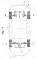
- Figure 11 shows an electric or hybrid sports car SC equipped with the rear electric axle RA arranged to drive the rear wheels RW of the car and a front axle FA arranged to drive the front wheels FW.
- a battery pack BAT is housed in the clearance area CL confined by the rear axle, while when the car is not (fully) electric, an internal combustion engine CE is housed therein. For this reason, the sign BAT/CE is indicated.
- each motor module MM is completely free of clutches, i.e. of mechanical parts having the function of connecting two shafts on command to allow or prevent and possibly modulate the transmission of the rotatory motion; in other words, a clutch is a mechanism which, using friction, allows a gradual separation/combination of the motion of two shafts which rotate at different speeds and the gear trains GT do not comprise any clutch interposing the transmission of the motion from the electric motor-generators EM to the corresponding drive wheels RW.
- the motor modules are fixed to the vehicle frame F and are preferably driven independently of each other, being mechanically independent, and thus allow the corresponding electric machines EM and the corresponding drive wheels RW to rotate at different rotation speeds, especially when driving around a bend.
- a VCU processing unit is configured to calculate a different rotation speed between the right output OUTR and the left output OUTL of the electric axle, for example based on a steering angle.
- This information is generally available on a vehicle data network CAN, since this data is essential for the various safety systems generally available on board the car, such as the ESP (Electronic Stability Program).
- the vehicle is equipped with an inverter for each of the motor generators so that it can control the power supply of each one independently.
- the VCU processing unit is programmed to perform regenerative braking allowing recovery of the electrical energy from the kinetic energy of the vehicle, when it needs to be decelerated.
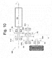
- Figure 10 shows a variant of the gear train of the motor module MM.
- two gearwheels of different diameter G1A and G1B are fitted onto the drive shaft, which mesh with respective gearwheels G2A and G2B fitted onto the intermediate shaft ISH.
- a DC synchronizer is arranged so as to allow one of the two geared wheels to be made rigidly connected with said intermediate shaft alternately.
- the gearwheels fitted onto the drive shaft SH are permanent, the gearwheels fitted onto the intermediate shaft are rotatably associated so as to allow the gear ratio to vary.
- Each secondary shaft SSH therefore has an outer end defined as an output OUT connected to a respective wheel by the above-described axle shaft DS (right DSR or left DSL).
- the inner end, opposite the output OUT, of the secondary shaft is permanently connected with an output shaft of the internal combustion engine gearbox.
- the rear electric axle RA equipped with right and left axle shafts has an Omega ⁇ shape.
- the front electric axle FA equipped with right and left axle shafts has an H shape.
- the synchronizer can be configured to disengage both the second gearwheels G2A and G2B. This can be useful to help the low-speed heat engine and disconnect the electric axle from the transmission, when the car exceeds a predetermined speed.
- a front electric axle FA is implemented as shown in figures 3, 4 , 8 and 11 , while the rear axle is driven only by the internal combustion engine CE.
- two casings are made by moulding using a single mould which simultaneously makes the right casing GTCR and the left casing GTCL in a single piece as shown in figure 3 .
- the two casings can be separated by cutting them. This aspect further contributes to optimizing the means and thus the production costs of the car alone according to the present invention.
- the car may comprise a single electric axle, front and/or rear, or both, and the three combinations obtained may still be combined with the presence of an internal combustion engine for a total of at least six combinations.
Landscapes
- Engineering & Computer Science (AREA)
- Mechanical Engineering (AREA)
- Transportation (AREA)
- Chemical & Material Sciences (AREA)
- Combustion & Propulsion (AREA)
- Power Engineering (AREA)
- General Engineering & Computer Science (AREA)
- Life Sciences & Earth Sciences (AREA)
- Sustainable Development (AREA)
- Sustainable Energy (AREA)
- Electric Propulsion And Braking For Vehicles (AREA)
- Hybrid Electric Vehicles (AREA)
- Arrangement Or Mounting Of Propulsion Units For Vehicles (AREA)
Claims (10)
- Elektro- oder Hybrid- (SC) Kraftfahrzeug mit vier Rädern (FW, RW), einer elektrischen Vorderachse (FA) und einer elektrischen Hinterachse (RA), wobei jede elektrische Achse (FA, RA) ein Paar Motormodule (MM) aufweist, die jeweils aufweisen:einen elektrischen Motorgenerator (EM) mit einer Relativantriebswelle (SH), die eine Drehachse (Y) identifiziert;eine Sekundärwelle (SSH);mindestens eine Zwischenwelle (ISH);einen Getriebezug, der auf der Antriebswelle (SH), der Sekundärwelle (SSH) und der Zwischenwelle (ISH) montiert ist, um eine Drehbewegung von der Antriebswelle (SH) auf die Sekundärwelle (SSH) und umgekehrt zu übertragen;ein Getriebegehäuse (GTC), das den Getriebezug umschließt, permanent an einem Stator des elektrischen Motorgenerators (EM) befestigt ist und eine längliche Form hat, die eine Erstreckungsachse (X) senkrecht zur Drehachse (Y) definiert,wobei in jedem Motormodul (MM) die Sekundärwelle (SSH) und die Zwischenwelle (ISH) parallel zur Antriebswelle (SH) angeordnet sind,wobei in jedem Motormodul (MM) die Antriebswelle (SH) und die Sekundärwelle (SSH) eine Ebene definieren, und wobei die Zwischenwelle (ISH) auf der Ebene liegt,wobei jedes Motormodul (MM) im Wesentlichen L-förmig ausgebildet ist,wobei in jeder elektrischen Achse (FA, RA) die beiden Motormodule (MM) wechselseitig und stabil einander zugeordnet sind, so dass die jeweiligen Antriebswellen (SHR, SHL) koaxial zueinander angeordnet sind,wobei das Elektrofahrzeug (SC) dadurch gekennzeichnet ist, dass:in der vorderen elektrischen Achse (FA) die Getriebegehäuse (GTCR, GTCL) der beiden Motormodule (MM) parallel zueinander angeordnet und wechselseitig miteinander verbunden sind, wodurch die elektrische Vorderachse (FA) eine T-Form erhält; undin der hinteren elektrischen Achse (FR) die Statoren der Motorgeneratoren (EMR, EML) der beiden Motormodule (MM) reziprok verbunden sind, so dass die Getriebegehäuse (GTCR, GTCL) parallel zueinander und in einer äußeren Position angeordnet sind, wodurch die hintere elektrische Achse (RA) eine U-Form erhält.
- Fahrzeug (SC) nach Anspruch 1, wobei jeder Getriebezug ein festes Übersetzungsverhältnis definiert.
- Fahrzeug (SC) nach Anspruch 1 oder 2, wobei jeder Getriebezug eine Vorrichtung zum Auswählen eines oder mehrerer Übersetzungsverhältnisse (G2A, G2B, DS) aufweist.
- Fahrzeug (SC) nach Anspruch 1, 2 oder 3, wobei jeder Getriebezug aufweist:ein erstes Zahnrad (G1), das auf der Antriebswelle (SH) montiert ist;ein zweites Zahnrad (G2), das mit dem ersten Zahnrad (G1) kämmt und auf der Zwischenwelle (ISH) montiert ist;ein drittes Zahnrad (G3), das auf der Zwischenwelle montiert ist; undein viertes Zahnrad (G4), das mit dem dritten Zahnrad (G3) kämmt und auf der Sekundärwelle (SSH) montiert ist.
- Fahrzeug (SC) nach einem der Ansprüche 1 bis 4, wobei jede Sekundärwelle (SSH) ein Ende aufweist, das einen außen angeordneten Abtrieb (OUTR, OUTL) des Motormoduls definiert, der dazu vorgesehen ist, betrieblich mit einer Achswelle (DSR, DSL) verbunden zu werden.
- Fahrzeug (SC) nach einem der Ansprüche 1 bis 5, wobei Drehachsen der vier Räder eine Ebene identifizieren, in der die Drehachse (Y) der Antriebswellen (SHR, SHL) und die Erstreckungsachsen der Getriebegehäuse (GTR, GTL) liegen.
- Fahrzeug (SC) nach Anspruch 6, wobei:die hintere elektrische Achse (RA) einen Freiraum (CL) in der Ebene definiert, der an drei Seiten durch die elektrische Achse (RA) und durch einen Fahrgastraum (AB) des Fahrzeugs begrenzt ist, undwobei ein Batteriepack (BAT) oder ein Verbrennungsmotor (CE) in dem Freiraumbereich aufgenommen ist.
- Fahrzeug (SC) nach Anspruch 7, wobei:der Batteriepack (BAT) im Freiraumbereich aufgenommen ist, undein Boden des Fahrzeugs (SC) eine verschließbare Öffnung aufweist, die das Herausnehmen des Batteriepacks (BAT) durch den Boden ermöglicht.
- Fahrzeug (SC) nach Anspruch 7 oder 8, wobei:jede Sekundärwelle ein erstes Ende, das einen außen angeordneten Abtrieb (OUTR, OUTL) des Motormoduls definiert, der dazu vorgesehen ist, im Betrieb mit einer Achswelle (DSR, DSL) verbunden zu werden, und ein dem ersten Ende gegenüberliegendes zweites Ende aufweist, undein Verbrennungsmotor (CE) im Freiraumbereich aufgenommen ist, der sein eigenes Getriebe und ein Paar Abtriebswellen aufweist, die jeweils mit einem relativen zweiten Ende der Sekundärwelle verbunden sind, um bei einer Führung der Hinterräder (RW) bezüglich einer Drehbewegung zusammenzuarbeiten.
- Fahrzeug (SC) nach Anspruch 7, 8 oder 9, wobei:die elektrische Vorderachse (FA) an der Vorderseite des Fahrgastraums (AB) angeordnet ist, wobei die Getriebegehäuse (GTCR, GTCL) nach hinten ausgerichtet sind, unddas Fahrzeug ferner ein Lenkgetriebe (SW) aufweist, das über der elektrischen Achse oder zwischen der vorderen elektrischen Achse (FA) und dem Fahrgastraum angeordnet ist.
Applications Claiming Priority (1)
| Application Number | Priority Date | Filing Date | Title |
|---|---|---|---|
| IT102018000007255A IT201800007255A1 (it) | 2018-07-17 | 2018-07-17 | Assale elettrico per un autoveicolo ed autoveicolo comprendente detto assale elettrico |
Publications (2)
| Publication Number | Publication Date |
|---|---|
| EP3597464A1 EP3597464A1 (de) | 2020-01-22 |
| EP3597464B1 true EP3597464B1 (de) | 2021-05-26 |
Family
ID=63834489
Family Applications (1)
| Application Number | Title | Priority Date | Filing Date |
|---|---|---|---|
| EP19186859.5A Active EP3597464B1 (de) | 2018-07-17 | 2019-07-17 | Kraftfahrzeug mit einer elektrischen achse |
Country Status (3)
| Country | Link |
|---|---|
| US (1) | US11021055B2 (de) |
| EP (1) | EP3597464B1 (de) |
| IT (1) | IT201800007255A1 (de) |
Cited By (2)
| Publication number | Priority date | Publication date | Assignee | Title |
|---|---|---|---|---|
| IT202300027021A1 (it) * | 2023-12-18 | 2025-06-18 | Ferrari Spa | Motore elettrico per autotrazione e veicolo stradale dotato di tale motore |
| WO2025186449A1 (fr) * | 2024-03-08 | 2025-09-12 | Ampere Sas | Module motopropulseur de vehicule automobile electrique, et groupe motopropulseur comportant deux modules motopropulseurs |
Families Citing this family (15)
| Publication number | Priority date | Publication date | Assignee | Title |
|---|---|---|---|---|
| DE102018221612A1 (de) * | 2018-12-13 | 2020-06-18 | Zf Friedrichshafen Ag | Elektromotorisch angetriebene Starrachse für Fahrzeuge, insbesondere Nutzfahrzeuge, mit radnahen Elektromotoren und Versatzgetrieben |
| CN112477686A (zh) * | 2020-12-15 | 2021-03-12 | 浙江吉利控股集团有限公司 | 一种无中间传动轴的换电式运载车辆 |
| IT202100004277A1 (it) * | 2021-02-24 | 2022-08-24 | Newtron Group Sa | Unità di motorizzazione per veicoli |
| US11850946B2 (en) | 2021-04-09 | 2023-12-26 | Dana Heavy Vehicle Systems Group, Llc | Electric drive axle system and operating method |
| US11529869B2 (en) | 2021-04-09 | 2022-12-20 | Dana Heavy Vehicle Systems Group, Llc | Electric drive axle system and operating method |
| US11981213B2 (en) | 2021-05-28 | 2024-05-14 | Dana Heavy Vehicle Systems Group, Llc | Electric drivetrain and method for operation of said drivetrain |
| US12491775B2 (en) | 2021-08-20 | 2025-12-09 | Dana Heavy Vehicle Systems Group, Llc | System and method for recirculating power |
| JP7521875B2 (ja) * | 2022-03-15 | 2024-07-24 | ダイハツ工業株式会社 | 車両後部構造 |
| JP2023144733A (ja) * | 2022-03-28 | 2023-10-11 | 住友電装株式会社 | 車両構造 |
| CN116080377B (zh) * | 2022-04-29 | 2024-01-26 | 比亚迪股份有限公司 | 电驱动总成、四轮驱动系统及车辆 |
| US20240336121A1 (en) * | 2023-04-04 | 2024-10-10 | Toyota Motor Engineering & Manufacturing North America, Inc. | Dual Electric Motor Assembly Systems and Methods |
| IT202300007071A1 (it) | 2023-04-13 | 2024-10-13 | Ferrari Spa | Assale ed autoveicolo comprendente tale assale |
| IT202300007101A1 (it) | 2023-04-13 | 2024-10-13 | Ferrari Spa | Autoveicolo |
| IT202300007065A1 (it) | 2023-04-13 | 2024-10-13 | Ferrari Spa | Autoveicolo |
| WO2025129304A1 (pt) * | 2023-12-19 | 2025-06-26 | Stara S/a. Industria De Implementos Agrícolas | Conjunto modular de unidade motriz elétrica |
Family Cites Families (11)
| Publication number | Priority date | Publication date | Assignee | Title |
|---|---|---|---|---|
| DE29518401U1 (de) * | 1995-11-20 | 1997-03-20 | Siemens AG, 80333 München | Fahrwerk für Nutzfahrzeuge |
| US20100006351A1 (en) | 2008-07-08 | 2010-01-14 | Howard J Scott | Electric vehicle with contra-recgarge system |
| US20100187024A1 (en) | 2009-01-29 | 2010-07-29 | Tesla Motors, Inc. | All wheel drive electric vehicle power assist drive system |
| US20110094807A1 (en) * | 2009-10-26 | 2011-04-28 | Steve Pruitt | Electric drive system for passive vehicle |
| DE102010017966A1 (de) * | 2010-04-23 | 2011-10-27 | Dr. Ing. H.C. F. Porsche Aktiengesellschaft | Fahrzeug mit elektrischem Antrieb |
| JP2012001196A (ja) * | 2010-06-12 | 2012-01-05 | Think Together:Kk | 電気自動車用足回りユニット |
| DE102011000482B4 (de) * | 2011-02-03 | 2023-09-28 | Dr. Ing. H.C. F. Porsche Aktiengesellschaft | Kraftfahrzeug |
| DE102012110269A1 (de) * | 2012-10-26 | 2014-04-30 | Dr. Ing. H.C. F. Porsche Aktiengesellschaft | Antriebsstrang eines rein elektrisch antreibbaren Kraftfahrzeugs |
| US10569638B2 (en) * | 2014-06-25 | 2020-02-25 | Heinz Welschoff | All electric vehicle without plug-in requirement |
| FR3052110B1 (fr) * | 2016-06-03 | 2018-07-06 | Peugeot Citroen Automobiles Sa | Essieu moteur standardise pour vehicule automobile, comportant des machines electriques |
| FR3053007B1 (fr) * | 2016-06-28 | 2019-08-23 | France Reducteurs | Transmission, notamment pour engin roulant, et engin roulant equipe d'une telle transmission |
-
2018
- 2018-07-17 IT IT102018000007255A patent/IT201800007255A1/it unknown
-
2019
- 2019-07-17 EP EP19186859.5A patent/EP3597464B1/de active Active
- 2019-07-17 US US16/513,863 patent/US11021055B2/en active Active
Cited By (3)
| Publication number | Priority date | Publication date | Assignee | Title |
|---|---|---|---|---|
| IT202300027021A1 (it) * | 2023-12-18 | 2025-06-18 | Ferrari Spa | Motore elettrico per autotrazione e veicolo stradale dotato di tale motore |
| WO2025186449A1 (fr) * | 2024-03-08 | 2025-09-12 | Ampere Sas | Module motopropulseur de vehicule automobile electrique, et groupe motopropulseur comportant deux modules motopropulseurs |
| FR3159929A1 (fr) * | 2024-03-08 | 2025-09-12 | Ampere Sas | Module motopropulseur de vehicule automobile electrique, et groupe motopropulseur comportant un tel module |
Also Published As
| Publication number | Publication date |
|---|---|
| US20200023734A1 (en) | 2020-01-23 |
| IT201800007255A1 (it) | 2020-01-17 |
| EP3597464A1 (de) | 2020-01-22 |
| US11021055B2 (en) | 2021-06-01 |
Similar Documents
| Publication | Publication Date | Title |
|---|---|---|
| EP3597464B1 (de) | Kraftfahrzeug mit einer elektrischen achse | |
| JP5806274B2 (ja) | 純電気式で駆動させることができる自動車のドライブトレイン | |
| JP6279102B2 (ja) | 自動車用統合操舵駆動軸及び電気自動車 | |
| US6880664B2 (en) | All-wheel drive vehicle with hybrid drive | |
| CN103998268B (zh) | 具有两台电动马达的纯电力驱动机动车辆动力的传动系 | |
| US9387756B1 (en) | Vehicle hybrid drive arrangement | |
| CN116018285A (zh) | 电动的机动车辆驱动器的尤其具有反相器组块或具有停车锁定设备的紧凑型驱动器组块 | |
| JP5457556B2 (ja) | 高速モータドライブシステムのためのドライブ構成 | |
| JP5465682B2 (ja) | ハイブリッド車の制御方法、制御装置、およびハイブリッド車 | |
| CN104245379B (zh) | 用于机动车的能转向的车桥的电动式动力总成 | |
| CN102673382A (zh) | 轮边动力混合的驱动系统 | |
| KR20110118578A (ko) | 전기 구동장치를 구비한 차량 | |
| EP2857243B1 (de) | Getriebevorrichtung | |
| JP2019502060A (ja) | 車両のパワートレイン | |
| JP2016002772A (ja) | 電動車両 | |
| EP3702191A1 (de) | Kraftübertragungsvorrichtung für ein fahrzeug mit allradantrieb | |
| JP5879054B2 (ja) | ハイブリッド車用駆動装置 | |
| CN117818324A (zh) | 用于车辆的动力总成、包括该动力总成的车辆和使用该动力总成的加热方法 | |
| CN102328576B (zh) | 混合动力车辆的驱动装置 | |
| EP4079552A1 (de) | Fahrzeugantriebsgerät | |
| JP3253342B2 (ja) | 電気自動車の駆動システム | |
| US8528682B2 (en) | Hybrid drive train | |
| CN211809037U (zh) | 车辆动力驱动系统和车辆 | |
| JP4791312B2 (ja) | トラクタ | |
| EP2921332B1 (de) | Antriebsstrang für ein Geländefahrzeug |
Legal Events
| Date | Code | Title | Description |
|---|---|---|---|
| PUAI | Public reference made under article 153(3) epc to a published international application that has entered the european phase |
Free format text: ORIGINAL CODE: 0009012 |
|
| STAA | Information on the status of an ep patent application or granted ep patent |
Free format text: STATUS: THE APPLICATION HAS BEEN PUBLISHED |
|
| AK | Designated contracting states |
Kind code of ref document: A1 Designated state(s): AL AT BE BG CH CY CZ DE DK EE ES FI FR GB GR HR HU IE IS IT LI LT LU LV MC MK MT NL NO PL PT RO RS SE SI SK SM TR |
|
| AX | Request for extension of the european patent |
Extension state: BA ME |
|
| STAA | Information on the status of an ep patent application or granted ep patent |
Free format text: STATUS: REQUEST FOR EXAMINATION WAS MADE |
|
| 17P | Request for examination filed |
Effective date: 20200721 |
|
| GRAJ | Information related to disapproval of communication of intention to grant by the applicant or resumption of examination proceedings by the epo deleted |
Free format text: ORIGINAL CODE: EPIDOSDIGR1 |
|
| GRAP | Despatch of communication of intention to grant a patent |
Free format text: ORIGINAL CODE: EPIDOSNIGR1 |
|
| GRAP | Despatch of communication of intention to grant a patent |
Free format text: ORIGINAL CODE: EPIDOSNIGR1 |
|
| STAA | Information on the status of an ep patent application or granted ep patent |
Free format text: STATUS: GRANT OF PATENT IS INTENDED |
|
| RIC1 | Information provided on ipc code assigned before grant |
Ipc: F16H 3/44 20060101ALI20201116BHEP Ipc: B60K 17/356 20060101ALI20201116BHEP Ipc: B60K 17/354 20060101ALI20201116BHEP Ipc: B60K 7/00 20060101ALI20201116BHEP Ipc: B60K 1/04 20190101AFI20201116BHEP |
|
| INTG | Intention to grant announced |
Effective date: 20201218 |
|
| GRAS | Grant fee paid |
Free format text: ORIGINAL CODE: EPIDOSNIGR3 |
|
| GRAA | (expected) grant |
Free format text: ORIGINAL CODE: 0009210 |
|
| STAA | Information on the status of an ep patent application or granted ep patent |
Free format text: STATUS: THE PATENT HAS BEEN GRANTED |
|
| AK | Designated contracting states |
Kind code of ref document: B1 Designated state(s): AL AT BE BG CH CY CZ DE DK EE ES FI FR GB GR HR HU IE IS IT LI LT LU LV MC MK MT NL NO PL PT RO RS SE SI SK SM TR |
|
| REG | Reference to a national code |
Ref country code: GB Ref legal event code: FG4D |
|
| REG | Reference to a national code |
Ref country code: CH Ref legal event code: EP |
|
| REG | Reference to a national code |
Ref country code: AT Ref legal event code: REF Ref document number: 1395871 Country of ref document: AT Kind code of ref document: T Effective date: 20210615 |
|
| REG | Reference to a national code |
Ref country code: DE Ref legal event code: R096 Ref document number: 602019004843 Country of ref document: DE |
|
| REG | Reference to a national code |
Ref country code: IE Ref legal event code: FG4D |
|
| REG | Reference to a national code |
Ref country code: LT Ref legal event code: MG9D |
|
| REG | Reference to a national code |
Ref country code: AT Ref legal event code: MK05 Ref document number: 1395871 Country of ref document: AT Kind code of ref document: T Effective date: 20210526 |
|
| PG25 | Lapsed in a contracting state [announced via postgrant information from national office to epo] |
Ref country code: HR Free format text: LAPSE BECAUSE OF FAILURE TO SUBMIT A TRANSLATION OF THE DESCRIPTION OR TO PAY THE FEE WITHIN THE PRESCRIBED TIME-LIMIT Effective date: 20210526 Ref country code: LT Free format text: LAPSE BECAUSE OF FAILURE TO SUBMIT A TRANSLATION OF THE DESCRIPTION OR TO PAY THE FEE WITHIN THE PRESCRIBED TIME-LIMIT Effective date: 20210526 Ref country code: FI Free format text: LAPSE BECAUSE OF FAILURE TO SUBMIT A TRANSLATION OF THE DESCRIPTION OR TO PAY THE FEE WITHIN THE PRESCRIBED TIME-LIMIT Effective date: 20210526 Ref country code: BG Free format text: LAPSE BECAUSE OF FAILURE TO SUBMIT A TRANSLATION OF THE DESCRIPTION OR TO PAY THE FEE WITHIN THE PRESCRIBED TIME-LIMIT Effective date: 20210826 Ref country code: AT Free format text: LAPSE BECAUSE OF FAILURE TO SUBMIT A TRANSLATION OF THE DESCRIPTION OR TO PAY THE FEE WITHIN THE PRESCRIBED TIME-LIMIT Effective date: 20210526 |
|
| REG | Reference to a national code |
Ref country code: NL Ref legal event code: MP Effective date: 20210526 |
|
| PG25 | Lapsed in a contracting state [announced via postgrant information from national office to epo] |
Ref country code: PL Free format text: LAPSE BECAUSE OF FAILURE TO SUBMIT A TRANSLATION OF THE DESCRIPTION OR TO PAY THE FEE WITHIN THE PRESCRIBED TIME-LIMIT Effective date: 20210526 Ref country code: LV Free format text: LAPSE BECAUSE OF FAILURE TO SUBMIT A TRANSLATION OF THE DESCRIPTION OR TO PAY THE FEE WITHIN THE PRESCRIBED TIME-LIMIT Effective date: 20210526 Ref country code: NO Free format text: LAPSE BECAUSE OF FAILURE TO SUBMIT A TRANSLATION OF THE DESCRIPTION OR TO PAY THE FEE WITHIN THE PRESCRIBED TIME-LIMIT Effective date: 20210826 Ref country code: SE Free format text: LAPSE BECAUSE OF FAILURE TO SUBMIT A TRANSLATION OF THE DESCRIPTION OR TO PAY THE FEE WITHIN THE PRESCRIBED TIME-LIMIT Effective date: 20210526 Ref country code: PT Free format text: LAPSE BECAUSE OF FAILURE TO SUBMIT A TRANSLATION OF THE DESCRIPTION OR TO PAY THE FEE WITHIN THE PRESCRIBED TIME-LIMIT Effective date: 20210927 Ref country code: RS Free format text: LAPSE BECAUSE OF FAILURE TO SUBMIT A TRANSLATION OF THE DESCRIPTION OR TO PAY THE FEE WITHIN THE PRESCRIBED TIME-LIMIT Effective date: 20210526 Ref country code: GR Free format text: LAPSE BECAUSE OF FAILURE TO SUBMIT A TRANSLATION OF THE DESCRIPTION OR TO PAY THE FEE WITHIN THE PRESCRIBED TIME-LIMIT Effective date: 20210827 Ref country code: IS Free format text: LAPSE BECAUSE OF FAILURE TO SUBMIT A TRANSLATION OF THE DESCRIPTION OR TO PAY THE FEE WITHIN THE PRESCRIBED TIME-LIMIT Effective date: 20210926 |
|
| PG25 | Lapsed in a contracting state [announced via postgrant information from national office to epo] |
Ref country code: NL Free format text: LAPSE BECAUSE OF FAILURE TO SUBMIT A TRANSLATION OF THE DESCRIPTION OR TO PAY THE FEE WITHIN THE PRESCRIBED TIME-LIMIT Effective date: 20210526 |
|
| PG25 | Lapsed in a contracting state [announced via postgrant information from national office to epo] |
Ref country code: SK Free format text: LAPSE BECAUSE OF FAILURE TO SUBMIT A TRANSLATION OF THE DESCRIPTION OR TO PAY THE FEE WITHIN THE PRESCRIBED TIME-LIMIT Effective date: 20210526 Ref country code: EE Free format text: LAPSE BECAUSE OF FAILURE TO SUBMIT A TRANSLATION OF THE DESCRIPTION OR TO PAY THE FEE WITHIN THE PRESCRIBED TIME-LIMIT Effective date: 20210526 Ref country code: ES Free format text: LAPSE BECAUSE OF FAILURE TO SUBMIT A TRANSLATION OF THE DESCRIPTION OR TO PAY THE FEE WITHIN THE PRESCRIBED TIME-LIMIT Effective date: 20210526 Ref country code: SM Free format text: LAPSE BECAUSE OF FAILURE TO SUBMIT A TRANSLATION OF THE DESCRIPTION OR TO PAY THE FEE WITHIN THE PRESCRIBED TIME-LIMIT Effective date: 20210526 Ref country code: RO Free format text: LAPSE BECAUSE OF FAILURE TO SUBMIT A TRANSLATION OF THE DESCRIPTION OR TO PAY THE FEE WITHIN THE PRESCRIBED TIME-LIMIT Effective date: 20210526 Ref country code: CZ Free format text: LAPSE BECAUSE OF FAILURE TO SUBMIT A TRANSLATION OF THE DESCRIPTION OR TO PAY THE FEE WITHIN THE PRESCRIBED TIME-LIMIT Effective date: 20210526 Ref country code: DK Free format text: LAPSE BECAUSE OF FAILURE TO SUBMIT A TRANSLATION OF THE DESCRIPTION OR TO PAY THE FEE WITHIN THE PRESCRIBED TIME-LIMIT Effective date: 20210526 |
|
| REG | Reference to a national code |
Ref country code: DE Ref legal event code: R097 Ref document number: 602019004843 Country of ref document: DE |
|
| PLBE | No opposition filed within time limit |
Free format text: ORIGINAL CODE: 0009261 |
|
| STAA | Information on the status of an ep patent application or granted ep patent |
Free format text: STATUS: NO OPPOSITION FILED WITHIN TIME LIMIT |
|
| PG25 | Lapsed in a contracting state [announced via postgrant information from national office to epo] |
Ref country code: MC Free format text: LAPSE BECAUSE OF FAILURE TO SUBMIT A TRANSLATION OF THE DESCRIPTION OR TO PAY THE FEE WITHIN THE PRESCRIBED TIME-LIMIT Effective date: 20210526 |
|
| REG | Reference to a national code |
Ref country code: BE Ref legal event code: MM Effective date: 20210731 |
|
| 26N | No opposition filed |
Effective date: 20220301 |
|
| PG25 | Lapsed in a contracting state [announced via postgrant information from national office to epo] |
Ref country code: IS Free format text: LAPSE BECAUSE OF FAILURE TO SUBMIT A TRANSLATION OF THE DESCRIPTION OR TO PAY THE FEE WITHIN THE PRESCRIBED TIME-LIMIT Effective date: 20210926 Ref country code: LU Free format text: LAPSE BECAUSE OF NON-PAYMENT OF DUE FEES Effective date: 20210717 Ref country code: AL Free format text: LAPSE BECAUSE OF FAILURE TO SUBMIT A TRANSLATION OF THE DESCRIPTION OR TO PAY THE FEE WITHIN THE PRESCRIBED TIME-LIMIT Effective date: 20210526 |
|
| PG25 | Lapsed in a contracting state [announced via postgrant information from national office to epo] |
Ref country code: IE Free format text: LAPSE BECAUSE OF NON-PAYMENT OF DUE FEES Effective date: 20210717 Ref country code: BE Free format text: LAPSE BECAUSE OF NON-PAYMENT OF DUE FEES Effective date: 20210731 |
|
| REG | Reference to a national code |
Ref country code: CH Ref legal event code: PL |
|
| PG25 | Lapsed in a contracting state [announced via postgrant information from national office to epo] |
Ref country code: LI Free format text: LAPSE BECAUSE OF NON-PAYMENT OF DUE FEES Effective date: 20220731 Ref country code: CH Free format text: LAPSE BECAUSE OF NON-PAYMENT OF DUE FEES Effective date: 20220731 |
|
| PG25 | Lapsed in a contracting state [announced via postgrant information from national office to epo] |
Ref country code: CY Free format text: LAPSE BECAUSE OF FAILURE TO SUBMIT A TRANSLATION OF THE DESCRIPTION OR TO PAY THE FEE WITHIN THE PRESCRIBED TIME-LIMIT Effective date: 20210526 |
|
| P01 | Opt-out of the competence of the unified patent court (upc) registered |
Effective date: 20230525 |
|
| PG25 | Lapsed in a contracting state [announced via postgrant information from national office to epo] |
Ref country code: HU Free format text: LAPSE BECAUSE OF FAILURE TO SUBMIT A TRANSLATION OF THE DESCRIPTION OR TO PAY THE FEE WITHIN THE PRESCRIBED TIME-LIMIT; INVALID AB INITIO Effective date: 20190717 |
|
| PG25 | Lapsed in a contracting state [announced via postgrant information from national office to epo] |
Ref country code: MK Free format text: LAPSE BECAUSE OF FAILURE TO SUBMIT A TRANSLATION OF THE DESCRIPTION OR TO PAY THE FEE WITHIN THE PRESCRIBED TIME-LIMIT Effective date: 20210526 |
|
| PG25 | Lapsed in a contracting state [announced via postgrant information from national office to epo] |
Ref country code: MT Free format text: LAPSE BECAUSE OF FAILURE TO SUBMIT A TRANSLATION OF THE DESCRIPTION OR TO PAY THE FEE WITHIN THE PRESCRIBED TIME-LIMIT Effective date: 20210526 |
|
| PGFP | Annual fee paid to national office [announced via postgrant information from national office to epo] |
Ref country code: DE Payment date: 20250728 Year of fee payment: 7 |
|
| PGFP | Annual fee paid to national office [announced via postgrant information from national office to epo] |
Ref country code: IT Payment date: 20250630 Year of fee payment: 7 |
|
| PGFP | Annual fee paid to national office [announced via postgrant information from national office to epo] |
Ref country code: GB Payment date: 20250722 Year of fee payment: 7 |
|
| PGFP | Annual fee paid to national office [announced via postgrant information from national office to epo] |
Ref country code: FR Payment date: 20250725 Year of fee payment: 7 |
|
| PG25 | Lapsed in a contracting state [announced via postgrant information from national office to epo] |
Ref country code: TR Free format text: LAPSE BECAUSE OF FAILURE TO SUBMIT A TRANSLATION OF THE DESCRIPTION OR TO PAY THE FEE WITHIN THE PRESCRIBED TIME-LIMIT Effective date: 20210526 |