EP3597161A1 - Sicherungsvorrichtung zur sicherung eines rollstuhls - Google Patents
Sicherungsvorrichtung zur sicherung eines rollstuhls Download PDFInfo
- Publication number
- EP3597161A1 EP3597161A1 EP19159347.4A EP19159347A EP3597161A1 EP 3597161 A1 EP3597161 A1 EP 3597161A1 EP 19159347 A EP19159347 A EP 19159347A EP 3597161 A1 EP3597161 A1 EP 3597161A1
- Authority
- EP
- European Patent Office
- Prior art keywords
- wheelchair
- seat
- backrest
- safety device
- seat surface
- Prior art date
- Legal status (The legal status is an assumption and is not a legal conclusion. Google has not performed a legal analysis and makes no representation as to the accuracy of the status listed.)
- Granted
Links
Images



Classifications
-
- B—PERFORMING OPERATIONS; TRANSPORTING
- B60—VEHICLES IN GENERAL
- B60R—VEHICLES, VEHICLE FITTINGS, OR VEHICLE PARTS, NOT OTHERWISE PROVIDED FOR
- B60R22/00—Safety belts or body harnesses in vehicles
- B60R22/02—Semi-passive restraint systems, e.g. systems applied or removed automatically but not both ; Manual restraint systems
- B60R22/023—Three-point seat belt systems comprising two side lower and one side upper anchoring devices
-
- A—HUMAN NECESSITIES
- A61—MEDICAL OR VETERINARY SCIENCE; HYGIENE
- A61G—TRANSPORT, PERSONAL CONVEYANCES, OR ACCOMMODATION SPECIALLY ADAPTED FOR PATIENTS OR DISABLED PERSONS; OPERATING TABLES OR CHAIRS; CHAIRS FOR DENTISTRY; FUNERAL DEVICES
- A61G3/00—Ambulance aspects of vehicles; Vehicles with special provisions for transporting patients or disabled persons, or their personal conveyances, e.g. for facilitating access of, or for loading, wheelchairs
- A61G3/08—Accommodating or securing wheelchairs or stretchers
- A61G3/0808—Accommodating or securing wheelchairs
-
- A—HUMAN NECESSITIES
- A61—MEDICAL OR VETERINARY SCIENCE; HYGIENE
- A61G—TRANSPORT, PERSONAL CONVEYANCES, OR ACCOMMODATION SPECIALLY ADAPTED FOR PATIENTS OR DISABLED PERSONS; OPERATING TABLES OR CHAIRS; CHAIRS FOR DENTISTRY; FUNERAL DEVICES
- A61G2220/00—Adaptations of particular transporting means
- A61G2220/16—Buses
-
- B—PERFORMING OPERATIONS; TRANSPORTING
- B60—VEHICLES IN GENERAL
- B60R—VEHICLES, VEHICLE FITTINGS, OR VEHICLE PARTS, NOT OTHERWISE PROVIDED FOR
- B60R22/00—Safety belts or body harnesses in vehicles
- B60R22/02—Semi-passive restraint systems, e.g. systems applied or removed automatically but not both ; Manual restraint systems
- B60R2022/027—Four-point seat belt systems, e.g. with the two upper points connected together
Definitions
- the present invention relates to a safety device for securing a wheelchair in a vehicle.
- Safety devices for securing wheelchairs in a vehicle are known per se. Such safety devices secure wheelchairs parked in the vehicle and, in particular, people sitting on the wheelchairs in such a way that they are restrained when the vehicle accelerates strongly, in particular against the direction of travel - when the vehicle brakes or suddenly stops, for example in the event of an accident. Such safety devices often use, like conventional restraint systems in passenger cars, belt systems for securing the wheelchair in the vehicle and / or for securing the person on the wheelchair.
- a securing device for securing a wheelchair in a vehicle comprising a seat with a seat surface and with a backrest, the seat surface being oriented essentially horizontally in a position of use, the seat surface being arranged over a horizontal pivot axis can be pivoted upwards into a vertical position, the backrest being at least partially shortened at its lower edge, so that the backrest does not extend to the intersection axis between the backrest plane and the seat plane, so that the outer circumferences of the two drive wheels of the wheelchair , when the wheelchair approaches the front of the seat, when its seat is in the vertical position, can get behind the backrest so that the wheelchair can get closer to the backrest of the seat, into a receiving position.
- a seat of a vehicle is equipped with a seat surface which is oriented horizontally in a normal position in a position of use when the seat is not being used by a wheelchair user.
- the seat enables the seat to be brought into an upright, vertical position in a manner that moves particularly close of the wheelchair to the seat.
- the backrest of the seat is shortened at least in sections, namely at least in the two sections along the intersection axis between the backrest and the seat surface in the use position of the seat surface, in which the drive wheels of a wheelchair should come to rest, that is to say they are spaced apart from this cutting axis.
- the backrest ends in the use position before reaching the seat surface, that is to say it is shortened, so that there is a free space between the backrest and seat surface.
- the lower edge of the backrest is thus higher than the cutting axis and preferably also higher than the seat in the use position and the seat is pivoted away so that it does not hinder the approach of a wheelchair, in particular the drive wheels of the wheelchair.
- the outer circumferences of the two usually relatively large drive wheels of the wheelchair can get behind the backrest, so that the wheelchair, in particular the backrest of the wheelchair, comes closer to the backrest of the seat into a receiving position can.
- the wheelchair is preferably oriented in the receiving position in the same way as the seat, that is to say the back of the seat and the back of a conventional wheelchair are both “behind” in the vehicle longitudinal direction, the two seat surfaces are “in front” of the backrests in the vehicle longitudinal direction.
- front and rear each refer to the longitudinal direction of the vehicle and the usual direction of travel of the vehicle.
- backrest and “seat surface” each refer to the relevant usable flat structures which are used for leaning or sitting, and do not include any further linkages, Frames and the like, which can connect the relevant “backrest” and “seat” surfaces.
- a “seat” can also be a bench seat, the seat surface can also offer space for several people.
- the seat surface of a seat can, for example, also be formed in several parts.
- the seat In the vertical position, the seat preferably lies essentially parallel to the backrest and adjacent to the backrest.
- the seat is preferably pivoted upwards at the front.
- the seat surface is then preferably also shortened at least in sections on its rear edge.
- the seat then also does not extend to the intersection axis between the backrest plane and the seat plane.
- the lower edge of the seat surface is preferably not deeper in the vertical position than the lower edge of the backrest.
- the seat is essentially normal to the backrest in the vertical position.
- the seat is preferably pivoted laterally into a vertical position.
- the seat surface is preferably formed in two parts and the two parts of the seat surface can be swung open in opposite directions.
- the backrest and / or the seat surface are preferably shortened over their entire extent along the intersection axis between the backrest plane and the seat surface plane.
- the backrest and / or the seat surface can be spaced apart from the cutting axis in at least two sections along the cutting axis, the two sections being arranged, in particular being so far apart, that both drive wheels of a conventional wheelchair can extend through these sections.
- the backrest and the seat surface are preferably shortened, at least in sections, at least 10 cm, preferably at least 15 cm, in particular these distances can exist over the entire extent along the cutting axis.
- the seat preferably comprises a belt system, the belt system being set up to secure a person on the wheelchair in the receiving position.
- the same belt system can preferably be used to secure a passenger on the seat in the use position, and also to secure a passenger sitting in a wheelchair, who is in the receiving position on the seat, with the seat in the vertical position.
- the belt system preferably comprises an H-belt in order to secure a person on the wheelchair in the receiving position.
- the two vertical belts of the H-belt can be used particularly preferably in the use position of the seat by two passengers on the seat as conventional 3-point belts.
- the safety device preferably comprises at least one wheelchair safety belt mounted in the floor of the vehicle and / or at least one wheelchair safety belt mounted in the seat, the or each wheelchair safety belt comprising a lock tongue as an end piece that the or each wheelchair safety belt can be accommodated in a respective belt buckle designed on the wheelchair.
- the seat preferably comprises a headrest, the headrest being set up to support the head of a person on the wheelchair in the receiving position.
- the same headrest can preferably also be used by a passenger on the seat in the use position.
- the headrest is preferably adjustable, in particular in its inclination or in its position in the longitudinal direction of the vehicle, so that the headrest can be adjusted to support either the head of a person on the seat in the use position or the head of a person on the wheelchair in the receiving position, too when the position of a person's head on the seat in the use position is usually further back than the position of a person's head on the wheelchair in the receiving position.
- the depth of the seat surface in the use position in the vehicle longitudinal direction is preferably so small that the upper edge of the seat surface in the vertical position lies below the usual push handles of the wheelchair in the receiving position.
- the swiveled-up seat is then in the vertical position, when the wheelchair is picked up, only at heights between the drive wheels on the one hand and the handles of the wheelchair on the other, so that the seat hinders the approach of a wheelchair even less.
- the seat is preferably designed as a bench, which in the use position offers space for at least two people on the seat.
- the seat can therefore include at least two headrests and at least two seat belts for passengers.
- the seat in particular the seat surface, preferably has an extension along the horizontal cutting axis between the backrest and the seat surface that is greater than the width of the wheelchair or a conventional wheelchair.
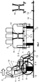
- a safety device according to the invention for securing a wheelchair in a vehicle is shown - on the left with a person in a wheelchair in a receiving position at the seat of the safety device and on the right without a wheelchair.
- the securing device comprises a seat 2 with a seat surface 3 and with a backrest 4.
- the seat is designed as a bench, which in a use position 5 offers space for at least two people or even three people on the seat.
- the seat surface 3 is oriented essentially horizontally in a use position 5, as is common for seat surfaces.
- the seat 3 is in the use position 5 in Fig. 1 only drawn in with dashed lines.
- the seat surface 3 can be pivoted upward into a vertical position 6 via a horizontal pivot axis Fig. 1 is shown as a normal, solid line.
- the seat 3 lies essentially parallel to the backrest 4 and adjacent to the backrest 4.
- the back 4 is shortened at its lower edge 7, so that the back 4 does not extend to the intersection axis between the back plane and the seat plane.
- the outer circumferences 8 of the two drive wheels of the wheelchair 1 can therefore come behind the backrest 4 when the wheelchair 1 approaches the seat 2 from the front, when the seat 3 of the seat 2 is in the vertical position 6, so that the wheelchair 1 comes closer the back 4 of the seat 2, can reach a receiving position, as in Fig. 1 , left figure.
- the seat or the bench comprises several headrests, with at least one headrest - namely the middle headrest here - being set up to support the head of a person on the wheelchair in the receiving position.
- At least one headrest can be adjustable, in particular in its inclination in the longitudinal direction of the vehicle - as in FIG Fig. 1 (left) shown above that the headrest can be adjusted to support either the head of a person on the seat 3 in the use position 5 or the head of a person on the wheelchair 1 in the receiving position.
- the seat 3 is also shortened at its rear edge 9 and does not reach the imaginary intersection axis between the backrest plane and the seat plane.
- the lower edge of the seat surface 3 ends in vertical position 6 at least as high as the lower edge of the backrest 4, so that the free space under the backrest is not blocked by the folded-up seat surface 3.
- the depth of the seat surface 3 in the use position 5 in the vehicle longitudinal direction is so small that the upper edge of the seat surface 3 in the vertical position 6 lies below the height of the usual push handles of the wheelchair 1 in the receiving position.
- the seat 3 is therefore in the height dimension between the push handles and the outer circumferences 8 of the drive wheels of a wheelchair 1 picked up.
- the safety device also comprises a belt system 10, for securing a person 11 on a wheelchair 1 (a wheelchair user), the belt system 10 in FIG Fig. 1 right representation is shown alone.
- the belt system 10 comprises an H-belt in order to secure a person 11 on the wheelchair 1 in the receiving position.
- the belt system 10 is attached to the seat 2.
- the safety device also comprises wheelchair safety belts (13) which can be mounted in the floor (12) of the vehicle, each wheelchair safety belt 13 comprises a lock tongue as an end piece, so that each wheelchair safety belt 13 can be accommodated in a respective belt buckle 14 formed on the wheelchair 1 - see 2 and 3 ,
- Fig. 3 shows the connection of a wheelchair safety belt 13 to the seat 2 in more detail, in a detail X, the Fig. 2 ,
- the safety belt 13 can be pulled out by a belt retractor 15 in the backrest 4 of the seat 2.
- Fig. 4 shows - analogous to the three representations of Fig. 1 - An alternative security device according to the invention.
- the seat 3 In the vertical position 6, the seat 3 is essentially normal to the backrest 4. More precisely, the seat 3 is formed in two parts and the two parts of the seat 3 can be pivoted sideways in opposite directions to reach the vertical position 6, so that each of the two Parts in the vertical position 6 is laterally arranged vertically, normally on the backrest 4 - see above all Fig. 4 middle representation.
- Fig. 5 shows the belt system 10 of the safety device in an alternative use: the same vertical belts, which form parts of the H-belt for securing a person in a wheelchair in the receiving position on the seat 2, can also be used to secure two people, when using the seat without Wheelchair, in a 3-point belt configuration of the belt system 10 can be used.
- the invention thus combines a total of full seats in a passenger transport with a wheelchair transport.
- a seat, seat 2 is provided with a foldable seat 3.
- the seat 2 has a belt system 10, preferably with automatic belt retractors 15.
- an H-belt system is used to better distribute the forces to the body of the wheelchair user 11 in the event of a crash to be able to.
- An additional belt system 13 is provided for the separate securing of the wheelchair 1.
- an additional headrest is installed on the seat 2, which can be tilted forward as in a passenger car and is adjustable in height. So that the wheelchair 1 can be integrated into the passenger space in a space-saving and optimal manner, the seat 2 must be designed as described above.
- the wheelchair user can be positioned as close as possible to the headrest, space must be created for the large rear wheels, namely the drive wheels of the wheelchair 1. This is done in that both the seat 3 is excluded in the rear area and the backrest 4 in the lower area.
- the seat 3 When the seat 3 is folded up, it preferably comes to rest under the handles of the wheelchair 1 but above the wheels or the outer circumference of the drive wheels 8.
- the axis of rotation is to be designed accordingly or the arms are to be shaped accordingly so that the seat 3 comes to lie in the desired position in the vertical position.
- the folding can be supported by spring force.
- a lock is provided.
- the shortened backrest 4 also allows the wheelchair 1 to move further back. The passenger space is thus optimally used and the wheelchair user 11 is brought into a good position with respect to the headrest.
- the headrest can also be made a little thicker or larger than usual to better bridge the distance to the head.
- This position of the wheelchair user can, for example, maintain two normal opposite seats in a group of four.
- the H-belt system can be used for the normal seat configuration as a conventional 3-point belt by adding additional belt tongues to the belt system.
- Belts are used to secure the wheelchair provided with automatic belt retractors 15, belt locks being provided on the wheelchair 1 to enable the wheelchair user to be quickly secured.
- These buckles are permanently attached to the frame, for example retrofitted. They enable reliable fixation, for example hoes, which attack the frame indefinitely. With the exception of the two belts on the floor of the vehicle, all of the belts are located on the seat system 1 and thus make it easy to convert a vehicle.
- the seat 1 is divided in the middle and is folded up sideways. As a result, the seat can be made longer, in particular without shortening.
Landscapes
- Health & Medical Sciences (AREA)
- Public Health (AREA)
- Life Sciences & Earth Sciences (AREA)
- Animal Behavior & Ethology (AREA)
- General Health & Medical Sciences (AREA)
- Veterinary Medicine (AREA)
- Engineering & Computer Science (AREA)
- Mechanical Engineering (AREA)
- Automotive Seat Belt Assembly (AREA)
- Seats For Vehicles (AREA)
Abstract
Description
- Die vorliegende Erfindung betrifft eine Sicherungsvorrichtung zur Sicherung eines Rollstuhls in einem Fahrzeug.
- Sicherungsvorrichtungen zur Sicherung von Rollstühlen in einem Fahrzeug sind an sich bekannt. Durch derartige Sicherungsvorrichtungen werden im Fahrzeug abgestellte Rollstühle und insbesondere auf den Rollstühlen sitzende Personen derart gesichert, dass diese bei starken Beschleunigungen des Fahrzeugs, insbesondere entgegen der Fahrtrichtung - beim Bremsen oder ruckartigen Anhalten des Fahrzeugs, beispielsweise bei einem Unfall - zurückgehalten werden. Solche Sicherungsvorrichtungen verwenden oft, wie auch übliche Rückhaltesysteme in Personenkraftwagen, Gurtsysteme zur Sicherung des Rollstuhls im Fahrzeug und/oder zur Sicherung der Person auf dem Rollstuhl.
- Meist sind in Fahrzeugen wie Bussen oder ähnlichen Personenbeförderungsfahrzeugen separate Stellplätze vorgesehen, die ausschließlich für die Nutzung durch Rollstuhlfahrer gedacht sind. Im öffentlichen Verkehr werden oft Stellplätze bereitgestellt, die nur über eine geringfügige Sicherung der Rollstühle mittels einfacher Schlaufen und Bügel als Umkippschutz verfügen. Der Raum wird bei Nichtbenutzung durch Rollstuhlfahrer für Stehplätze und/oder für eine Nutzung durch Klappsessel mit geringem Sitzkomfort genutzt.
- Es ist eine Aufgabe der Erfindung, eine Sicherungsvorrichtung, zur Sicherung eines Rollstuhls in einem Fahrzeug, anzugeben, die eine zuverlässige Sicherung eines Rollstuhls ermöglicht und dabei bei Nichtbenutzung durch einen Rollstuhl eine komfortable Sitzmöglichkeit für andere Passagiere zur Verfügung stellt.
- Die Lösung der Aufgabe erfolgt durch eine Sicherungsvorrichtung, zur Sicherung eines Rollstuhls in einem Fahrzeug, wobei die Sicherungsvorrichtung einen Sitz mit einer Sitzfläche und mit einer Lehne umfasst, wobei die Sitzfläche in einer Gebrauchsposition im Wesentlichen horizontal ausgerichtet ist, wobei die Sitzfläche über eine horizontale Schwenkachse nach oben in eine Vertikalposition geschwenkt werden kann, wobei die Lehne an ihrer Unterkante zumindest abschnittsweise verkürzt ausgebildet ist, so dass die Lehne nicht bis zur Schnittachse zwischen der Lehnen-Ebene und der Sitzflächen-Ebene reicht, so dass die Außenumfänge der beiden Antriebsräder des Rollstuhls, bei einer Annäherung des Rollstuhls von vorne an den Sitz, wenn sich dessen Sitzfläche in Vertikalposition befindet, hinter die Lehne gelangen können, so dass der Rollstuhl näher an die Lehne des Sitzes, in eine Aufnahmeposition, gelangen kann.
- Erfindungsgemäß ist ein Sitz eines Fahrzeuges mit einer Sitzfläche ausgestattet, die in einer Gebrauchsposition, bei Nicht-Benutzung des Sitzes durch einen Rollstuhlfahrer, in üblicher Weise horizontal ausgerichtet ist. Um die Benutzung von Teilen des Sitzes zur Sicherung des Rollstuhls und/oder zur Sicherung einer Person auf dem Rollstuhl besser nutzen zu können, ermöglicht es der Sitz die Sitzfläche in eine aufrechte, vertikale Position zu bringen, in einer Weise die ein besonders nahes heranfahren des Rollstuhls an den Sitz ermöglicht. Die Lehne des Sitzes ist zumindest abschnittsweise, nämlich zumindest in den beiden Abschnitten entlang der Schnittachse zwischen Lehne und Sitzfläche in Gebrauchsstellung der Sitzfläche, in denen die Antriebsräder eines Rollstuhls zu liegen kommen sollen, verkürzt ausgebildet, also von dieser Schnittachse beabstandet. Mit anderen Worten endet die Lehne vor Erreichen der Sitzfläche in Gebrauchsstellung, ist also verkürzt ausgebildet, so dass ein Freiraum zwischen Lehne und Sitzfläche besteht. Wenn sich die Sitzfläche in Vertikalposition befindet, liegt somit die Unterkante der Lehne höher als die Schnittachse und bevorzugt auch höher als die Sitzfläche in Gebrauchsstellung und die Sitzfläche ist weggeschwenkt, so dass sie die Annäherung eines Rollstuhls, insbesondere der Antriebsräder des Rollstuhls, nicht hindert. Bei einer Annäherung des Rollstuhls von vorne an den Sitz können daher die Außenumfänge der beiden üblicherweise relativ großen Antriebsräder des Rollstuhls hinter die Lehne gelangen, so dass der Rollstuhl, insbesondere die Lehne des Rollstuhls, näher an die Lehne des Sitzes, in eine Aufnahmeposition, gelangen kann. Der Rollstuhl ist dabei in der Aufnahmeposition bevorzugt gleich orientiert wie der Sitz, das heißt die Lehne des Sitzes und die Lehne eines üblichen Rollstuhls liegen beide "hinten" in Fahrzeuglängsrichtung, die beiden Sitzflächen befinden sich "vor" den Lehnen in Fahrzeuglängsrichtung.
- Die Bezeichnungen "vorne" und "hinten" beziehen sich in dieser Schrift jeweils auf die Fahrzeuglängsrichtung und die übliche Fahrtrichtung des Fahrzeuges.
- Die Bezeichnungen "Lehne" sowie "Sitzfläche" beziehen sich in dieser Schrift jeweils auf die betreffenden nutzbaren Flächengebilde, die zum Anlehnen bzw. zum Sitzen dienen, und umfassen nicht weitere Gestänge, Rahmen und dergleichen, die die betreffenden Flächen "Lehne" und "Sitzfläche" miteinander verbinden können.
- Ein "Sitz" kann im Rahmen der vorliegenden Schrift auch eine Sitzbank sein, die Sitzfläche kann auch für mehrere Personen Platz bieten. Die Sitzfläche eines Sitzes kann beispielsweise auch mehrteilig ausgebildet sein.
- Weiterbildungen der Erfindung sind in den abhängigen Ansprüchen, der Beschreibung sowie den beigefügten Zeichnungen angegeben.
- Bevorzugt liegt die Sitzfläche in der Vertikalposition im Wesentlichen parallel zur Lehne und benachbart zur Lehne. Die Sitzfläche wird dazu bevorzugt vorne nach oben geschwenkt. Die Sitzfläche ist dann vorzugsweise an ihrer Hinterkante ebenfalls zumindest abschnittsweise verkürzt ausgebildet. Die Sitzfläche reicht dann ebenfalls nicht bis zur Schnittachse zwischen der Lehnen-Ebene und der Sitzflächen-Ebene. Die Unterkante der Sitzfläche liegt vorzugsweise in Vertikalstellung nicht tiefer, als die Unterkante der Lehne.
- Gemäß einer anderen Ausführung steht die Sitzfläche in der Vertikalposition im Wesentlichen normal auf die Lehne. Die Sitzfläche wird bevorzugt seitlich in eine Vertikalposition geschwenkt. Die Sitzfläche wird insbesondere in diesem Fall vorzugsweise zweiteilig ausgebildet und die beiden Teile der Sitzfläche können in entgegengesetzte Richtungen aufgeschwenkt werden.
- Vorzugsweise sind die Lehne und/oder die Sitzfläche über ihre gesamte Erstreckung entlang der Schnittachse zwischen der Lehnen-Ebene und der Sitzflächen-Ebene verkürzt ausgebildet.
- Alternativ können die Lehne und/oder die Sitzfläche in zumindest zwei Abschnitten entlang der Schnittachse von der Schnittachse beabstandet sein, wobei die zwei Abschnitte so angeordnet sind, insbesondere so weit voneinander entfernt liegen, dass beide Antriebsräder eines üblichen Rollstuhls durch diese Abschnitte reichen können.
- Bevorzugt sind die Lehne und die Sitzfläche zumindest abschnittsweise zumindest 10 cm, bevorzugt zumindest 15 cm, verkürzt ausgebildet, insbesondere können diese Abstände über die gesamte Erstreckung entlang der Schnittachse bestehen.
- Vorzugsweise umfasst der Sitz ein Gurtsystem, wobei das Gurtsystem dazu eingerichtet ist, eine Person auf dem Rollstuhl in der Aufnahmeposition zu sichern. Das selbe Gurtsystem kann bevorzugt zur Sicherung eines Passagiers auf der Sitzfläche in der Gebrauchsstellung verwendet werden, sowie auch zur Sicherung eines Passagiers der im Rollstuhl sitzt, welcher sich in der Aufnahmeposition am Sitz befindet, bei Vertikalposition der Sitzfläche.
- Bevorzugt umfasst das Gurtsystem einen H-Gurt um eine Person auf dem Rollstuhl in der Aufnahmeposition zu sichern. Die beiden vertikalen Gurte des H-Gurtes können besonders bevorzugt in der Gebrauchsstellung der Sitzfläche von zwei Passagieren auf der Sitzfläche als herkömmliche 3-Punkt-Gurte verwendet werden.
- Vorzugsweise umfasst die Sicherungsvorrichtung zumindest einen im Boden des Fahrzeugs montierten Rollstuhlsicherungsgurt und/oder zumindest einen im Sitz montierten Rollstuhlsicherungsgurt, wobei der oder jeder Rollstuhlsicherungsgurt eine Schlosszunge als Endstück umfasst, so dass der oder jeder Rollstuhlsicherungsgurt in ein jeweiliges am Rollstuhl ausgebildetes Gurtschloss aufgenommen werden kann.
- Der Sitz umfasst bevorzugt eine Kopfstütze, wobei die Kopfstütze dazu eingerichtet ist, den Kopf einer Person auf dem Rollstuhl in der Aufnahmeposition abzustützen. Die selbe Kopfstütze kann bevorzugt auch von einem Passagier auf der Sitzfläche in der Gebrauchsstellung verwendet werden.
- Bevorzugt ist die Kopfstütze verstellbar, insbesondere in ihrer Neigung oder in ihrer Position in Fahrzeuglängsrichtung, so dass die Kopfstütze dazu eingestellt werden kann, entweder den Kopf einer Person auf der Sitzfläche in Gebrauchsstellung oder den Kopf einer Person auf dem Rollstuhl in der Aufnahmeposition abzustützen, auch wenn die Position des Kopfes einer Person auf der Sitzfläche in Gebrauchsstellung üblicherweise weiter hinten liegt, als die Position des Kopfes einer Person auf dem Rollstuhl in der Aufnahmeposition.
- Die Tiefe der Sitzfläche in der Gebrauchsstellung in Fahrzeuglängsrichtung ist bevorzugt so gering, dass die Oberkante der Sitzfläche in der Vertikalstellung unterhalb von üblichen Schiebegriffen des Rollsuhls in der Aufnahmeposition liegt. Die hochgeschwenkte Sitzfläche befindet sich dann in der Vertikalstellung, bei aufgenommenem Rollstuhl, nur auf Höhen zwischen den Antriebsrädern einerseits und den Griffen des Rollstuhls andererseits, so dass die Sitzfläche die Annäherung eines Rollstuhls noch weniger behindert.
- Der Sitz ist vorzugsweise als Bank ausgebildet, die in der Gebrauchsstellung zumindest zwei Personen auf der Sitzfläche Platz bietet. Der Sitz kann daher zumindest zwei Kopfstützen umfassen und zumindest zwei Gurte für Passagiere auf der Sitzfläche.
- Der Sitz, insbesondere die Sitzfläche, hat entlang der horizontalen Schnittachse zwischen Lehne und Sitzfläche bevorzugt eine Erstreckung die größer ist, als die Breite des Rollstuhls, bzw. eines üblichen Rollstuhls.
- Die Erfindung wird im Folgenden beispielhaft unter Bezugnahme auf die Zeichnungen beschrieben.
- Fig. 1
- ist eine schematische Ansicht einer erfindungsgemäßen Sicherungsvorrichtung zur Sicherung eines Rollstuhls in einem Fahrzeug von der Seite (links, mit Rollstuhl und Rollstuhlfahrer) und von vorne (mitte, ohne Rollstuhl und Rollstuhlfahrer), sowie des Gurtsystems der Sicherungsvorrichtung alleine (rechts).
- Fig. 2
- ist eine schematische Ansicht einer erfindungsgemäßen Sicherungsvorrichtung gemäß
Fig. 1 von der Seite, mit Rollstuhl jedoch ohne Rollstuhlfahrer, und zeigt die Position des Details X. - Fig. 3
- ist eine schematische Detaildarstellung des Details X gemäß
Fig. 2 . - Fig. 4
- ist eine schematische Ansicht einer alternativen erfindungsgemäßen Sicherungsvorrichtung zur Sicherung eines Rollstuhls in einem Fahrzeug von der Seite (links, mit Rollstuhl und Rollstuhlfahrer) und von vorne (mitte, ohne Rollstuhl und Rollstuhlfahrer), sowie des Gurtsystems der Sicherungsvorrichtung alleine (rechts).
- Fig. 5
- ist eine schematische Ansicht der Sicherungsvorrichtung gemäß
Fig. 1 (mitte), wobei sich das Gurtsystem der Sicherungsvorrichtung in einer alternativen Verwendungsstellung befindet. - In
Fig. 1 (links und mitte) ist eine erfindungsgemäße Sicherungsvorrichtung zur Sicherung eines Rollstuhls in einem Fahrzeug dargestellt - links mit einer Person in einem Rollstuhl in einer Aufnahmeposition am Sitz der Sicherungseinrichtung und rechts ohne Rollstuhl. - Die Sicherungsvorrichtung umfasst einen Sitz 2 mit einer Sitzfläche 3 und mit einer Lehne 4.
- Der Sitz ist als Bank ausgebildet, die in einer Gebrauchsposition 5 zumindest zwei Personen oder auch drei Personen auf der Sitzfläche Platz bietet.
- Die Sitzfläche 3 ist in einer Gebrauchsposition 5 im Wesentlichen horizontal ausgerichtet, wie für Sitzflächen allgemein üblich. Die Sitzfläche 3 ist in der Gebrauchsposition 5 in
Fig. 1 lediglich mit gestrichelten Linien eingezeichnet. - Über eine horizontale Schwenkachse kann die Sitzfläche 3 jedoch nach oben, in eine Vertikalposition 6, geschwenkt werden, die in
Fig. 1 als normale, durchgezogene Linie dargestellt ist. - Die Sitzfläche 3 liegt in der Vertikalposition 6 im Wesentlichen parallel zur Lehne 4 und benachbart zur Lehne 4.
- Die Lehne 4 ist an ihrer Unterkante 7 verkürzt ausgebildet, so dass die Lehne 4 nicht bis zur Schnittachse zwischen der Lehnen-Ebene und der Sitzflächen-Ebene reicht. Unterhalb der Unterkante 7 der Lehne 4 - die Oberhalb der Sitzfläche 3 in Gebrauchsposition 5 liegt - befindet sich ein Freiraum, durch welchen beispielsweise die Antriebsräder eines Rollstuhls hindurchreichen können. Die Außenumfänge 8 der beiden Antriebsräder des Rollstuhls 1 können daher bei einer Annäherung des Rollstuhls 1 von vorne an den Sitz 2, wenn sich die Sitzfläche 3 des Sitzes 2 in Vertikalposition 6 befindet, hinter die Lehne 4 gelangen, so dass der Rollstuhl 1 näher an die Lehne 4 des Sitzes 2, in eine Aufnahmeposition, gelangen kann, wie in
Fig. 1 , linke Abbildung, dargestellt. - Die Bezeichnungen "vorne" und "hinten" beziehen sich dabei immer auf die übliche Fahrtrichtung "F" des Fahrzeuges, dessen Boden durch die Linie 12 angedeutet ist.
- Der Sitz bzw. die Bank umfasst mehrere Kopfstützen, wobei zumindest eine Kopfstütze - nämlich hier die mittlere Kopfstütze - dazu eingerichtet ist, den Kopf einer Person auf dem Rollstuhl in der Aufnahmeposition abzustützen.
- Zumindest eine Kopfstütze kann verstellbar sein, insbesondere in ihrer Neigung in Fahrzeuglängsrichtung - wie in
Fig. 1 (links) dargestellt, so dass die Kopfstütze dazu eingestellt werden kann, entweder den Kopf einer Person auf der Sitzfläche 3 in Gebrauchsposition 5 oder den Kopf einer Person auf dem Rollstuhl 1 in der Aufnahmeposition abzustützen. - In der Ausführungsform der Sicherungsvorrichtung der
Fig. 1 ist die Sitzfläche 3 an ihrer Hinterkante 9 ebenfalls verkürzt ausgebildet und erreicht nicht die gedachte Schnittachse zwischen der Lehnen-Ebene und der Sitzflächen-Ebene. Hierdurch endet die Unterkante der Sitzfläche 3 in Vertikalposition 6 zumindest gleich hoch, wie die Unterkante der Lehne 4, so dass der Freiraum unter der Lehne nicht durch die hochgeklappte Sitzfläche 3 blockiert wird. - Die Tiefe der Sitzfläche 3 ist in der Gebrauchsstellung 5 in Fahrzeuglängsrichtung (siehe Fahrtrichtung F) so gering, dass die Oberkante der Sitzfläche 3 in der Vertikalstellung 6 unterhalb der Höhe von üblichen Schiebegriffen des Rollsuhls 1 in der Aufnahmeposition liegt. Die Sitzfläche 3 liegt daher in der Höhendimension zwischen den Schiebegriffen und den Außenumfängen 8 der Antriebsräder eines aufgenommenen Rollstuhls 1.
- Die Sicherungsvorrichtung umfasst auch ein Gurtsystem 10, zur Sicherung einer Person 11 auf einem aufgenommenen Rollstuhl 1 (eines Rollstuhlfahrers), wobei das Gurtsystem 10 in der
Fig. 1 rechte Darstellung alleine dargestellt ist. - Das Gurtsystem 10 umfasst einen H-Gurt um eine Person 11 auf dem Rollstuhl 1 in der Aufnahmeposition zu sichern. Das Gurtsystem 10 ist dabei am Sitz 2 befestigt.
- Die Sicherungsvorrichtung umfasst auch im Boden (12) des Fahrzeugs montierbare Rollstuhlsicherungsgurte (13), wobei jeder Rollstuhlsicherungsgurt 13 eine Schlosszunge als Endstück umfasst, so dass jeder Rollstuhlsicherungsgurt 13 in ein jeweiliges am Rollstuhl 1 ausgebildetes Gurtschloss 14 aufgenommen werden kann - siehe
Fig. 2 und Fig. 3 . -
Fig. 3 zeigt die Anbindung eines Rollstuhlsicherungsgurts 13 am Sitz 2 genauer, in einem Detail X, derFig. 2 . Der Sicherungsgurt 13 kann von einem Gurtaufroller 15 in der Lehne 4 des Sitzes 2 ausgezogen werden. -
Fig. 4 zeigt - analog zu den drei Darstellungen derFig. 1 - eine alternative erfindungsgemäße Sicherungsvorrichtung. Dabei steht die Sitzfläche 3 in der Vertikalposition 6 im Wesentlichen normal auf die Lehne 4. Genauer ist die Sitzfläche 3 hierbei zweiteilig ausgebildet und die beiden Teile der Sitzfläche 3 können zum Erreichen der Vertikalposition 6 in entgegengesetzte Richtungen seitlich hochgeschwenkt werden, so dass jeder der beiden Teile in der Vertikalposition 6 seitlich vertikal angeordnet ist, normal auf die Lehne 4 - siehe vor allemFig. 4 mittlere Darstellung. -
Fig. 5 zeigt das Gurtsystem 10 der Sicherungsvorrichtung in einer alternativen Verwendung: die selben vertikalen Gurte, die Teile des H-Gurts zur Sicherung einer Person in einem Rollstuhl in der Aufnahmeposition am Sitz 2 bilden, können auch zur Sicherung von zwei Personen, bei Verwendung der Sitzbank ohne Rollstuhl, in einer 3 Punktgurtkonfiguration des Gurtsystems 10, genutzt werden. - Die Erfindung kombiniert somit insgesamt vollwertige Sitzplätze einer Personenbeförderung mit einer Rollstuhlbeförderung. Dabei ist eine Sitzbank, Sitz 2, mit einer klappbaren Sitzfläche 3 versehen. Außerdem verfügt die Sitzbank 2 über eine Gurtsystem 10, vorzugsweise mit automatischen Gurtaufrollern 15. Im Idealfall wird ein H-Gurtsystem genutzt um die Kräfte im Crashfall besser auf den Körper des Rollstuhlfahrers 11 verteilen zu können. Ein zusätzliches Gurtsystem 13 ist für die separate Sicherung des Rollstuhls 1 vorgesehen. Außerdem ist eine zusätzliche Kopfstütze an der Sitzbank 2 installiert, die sich wie in einem Personenwagen nach vorn neigen läßt und in der Höhe anpassbar ist. Damit der Rollstuhl 1 platzsparend und optimal in den Passagierraum integriert werden kann, muss die Sitzbank 2 wie zuvor beschrieben ausgeführt sein. Damit der Rollstuhlfahrer möglichst nahe an der Kopfstütze positioniert werden kann, muss für die großen Hinterräder, nämlich die Antriebsräder des Rollstuhls 1, Platz geschaffen werden. Dies geschieht dadurch, dass sowohl die Sitzfläche 3 im hinteren Bereich ausgenommen ist als auch die Lehne 4 im unteren Bereich. Bei hochgeklappter Sitzfläche 3 kommt diese vorzugsweise unter den Griffen des Rollstuhls 1 zu liegen aber oberhalb der Räder bzw. des Außenumfangs der Antriebsräder 8.
- Die Drehachse ist entsprechend auszulegen bzw. auch die Arme sind entsprechend zu formen damit die Sitzfläche 3 in der Vertikalposition in der gewünschten Position zu liegen kommt. Dabei kann das Hochklappen durch Federkraft unterstützt sein. Bei heruntergeklappter Sitzfläche 3 ist eine Verriegelung vorgesehen. Die gekürzte Lehne 4 lässt den Rollstuhl 1 ebenfalls weiter nach hinten rücken. Damit wird der Passagierraum optimal ausgenutzt und der Rollstuhlfahrer 11 in eine gute Position zur Kopfstütze gebracht.
- Die Kopfstütze kann zusätzlich etwas dicker bzw. größer als gewöhnlich ausgeführt sein um den Abstand zum Kopf besser zu überbrücken. Durch diese Position des Rollstuhlfahrers können zum Beispiel in einer Vierersitzgruppe zwei normale gegenüberliegende Sitzplätze erhalten werden. Das H-Gurtsystem kann für die normale Sitzkonfiguration als herkömmlicher 3-Punktgurt genutzt werden, indem zusätzliche Gurtzungen am Gurtsystem vorhanden sind. Für die Rollstuhlsicherung sind Gurte mit automatischen Gurtaufrollern 15 vorgesehen, wobei Gurtschlösser am Rollstuhl 1 vorhanden sind, um eine rasche Sicherung des Rollstuhlfahrers zu ermöglichen. Diese Gurtschlösser sind am Rahmen fix montiert, beispielsweise nachgerüstet. Sie ermöglichen eine zuverlässige Fixierung als beispielsweise Hacken, die undefiniert am Rahmen angreifen. Somit befinden sich, bis auf die beiden Gurte am Boden des Fahrzeugs, alle Gurte auf dem Sitzsystem 1 und ermöglichen so einen einfachen Umbau eines Fahrzeuges.
- Bei einer Alternativlösung ist die Sitzfläche 1 mittig geteilt und wird jeweils seitwärts hochgeklappt. Dadurch kann die Sitzfläche länger ausgebildet werden, insbesondere ohne Verkürzung.
-
- 1
- Rollstuhl
- 2
- Sitz
- 3
- Sitzfläche
- 4
- Lehne
- 5
- Gebrauchsposition
- 6
- Vertikalposition
- 7
- Unterkante Lehne
- 8
- Außenumfang eines Antriebsrades
- 9
- Hinterkante Sitzfläche
- 10
- Gurtsystem
- 11
- Person auf dem Rollstuhl
- 12
- Boden des Fahrzeugs
- 13
- Rollstuhlsicherungsgurt
- 14
- Gurtschloss
- 15
- Gurtaufroller
- X
- Detailausschnitt
- F
- Fahrtrichtung
Claims (14)
- Sicherungsvorrichtung zur Sicherung eines Rollstuhls (1) in einem Fahrzeug, wobei die Sicherungsvorrichtung einen Sitz (2) mit einer Sitzfläche (3) und mit einer Lehne (4) umfasst, wobei die Sitzfläche (3) in einer Gebrauchsposition (5) im Wesentlichen horizontal ausgerichtet ist, wobei die Sitzfläche (3) über eine horizontale Schwenkachse nach oben in eine Vertikalposition (6) geschwenkt werden kann,
dadurch gekennzeichnet, dass die Lehne (4) an ihrer Unterkante (7) zumindest abschnittsweise verkürzt ausgebildet ist, so dass die Lehne (4) nicht bis zur Schnittachse zwischen der Lehnen-Ebene und der Sitzflächen-Ebene reicht, so dass die Außenumfänge (8) der beiden Antriebsräder des Rollstuhls (1), bei einer Annäherung des Rollstuhls (1) von vorne an den Sitz (2), wenn sich die Sitzfläche (3) des Sitzes (2) in Vertikalposition (6) befindet, hinter die Lehne (4) gelangen können, so dass der Rollstuhl (1) näher an die Lehne (4) des Sitzes (2), in eine Aufnahmeposition, gelangen kann. - Sicherungsvorrichtung nach Anspruch 1,
dadurch gekennzeichnet, dass die Sitzfläche (3) in der Vertikalposition (6) im Wesentlichen parallel zur Lehne (4) und benachbart zur Lehne (4) liegt, wobei die Sitzfläche (3) an ihrer Hinterkante (9) zumindest abschnittsweise verkürzt ausgebildet ist. - Sicherungsvorrichtung nach Anspruch 1,
dadurch gekennzeichnet, dass die Sitzfläche (3) in der Vertikalposition (6) im Wesentlichen normal auf die Lehne (4) steht, wobei bevorzugt die Sitzfläche (3) zweiteilig ausgebildet ist und die beiden Teile der Sitzfläche (3) zum Erreichen der Vertikalposition (6) in entgegengesetzte Richtungen aufgeschwenkt werden. - Sicherungsvorrichtung nach zumindest einem der vorhergehenden Ansprüche,
dadurch gekennzeichnet, dass die Lehne (4) und/oder die Sitzfläche (3) über ihre gesamte Erstreckung entlang der Schnittachse zwischen der Lehnen-Ebene und der Sitzflächen-Ebene verkürzt ausgebildet sind. - Sicherungsvorrichtung nach zumindest einem der vorhergehenden Ansprüche,
dadurch gekennzeichnet, dass die Lehne (4) und/oder die Sitzfläche (3) zumindest abschnittsweise zumindest 10 cm, bevorzugt zumindest 15 cm, verkürzt sind. - Sicherungsvorrichtung nach zumindest einem der vorhergehenden Ansprüche,
dadurch gekennzeichnet, dass der Sitz (2) ein Gurtsystem (10) umfasst, wobei das Gurtsystem (10) dazu eingerichtet ist, eine Person (11) auf dem Rollstuhl (1) in der Aufnahmeposition zu sichern. - Sicherungsvorrichtung nach zumindest einem der vorhergehenden Ansprüche,
dadurch gekennzeichnet, dass das Gurtsystem (10) einen H-Gurt umfasst um eine Person (11) auf dem Rollstuhl (1) in der Aufnahmeposition zu sichern. - Sicherungsvorrichtung nach zumindest einem der vorhergehenden Ansprüche,
dadurch gekennzeichnet, dass die Sicherungsvorrichtung zumindest einen im Boden (12) des Fahrzeugs montierbaren Rollstuhlsicherungsgurt (13) und/oder zumindest einen im Sitz (2) montierten Rollstuhlsicherungsgurt (13) umfasst, wobei der oder jeder Rollstuhlsicherungsgurt (13) eine Schlosszunge als Endstück umfasst, so dass der oder jeder Rollstuhlsicherungsgurt (13) in ein jeweiliges am Rollstuhl (1) ausgebildetes Gurtschloss (14) aufgenommen werden kann. - Sicherungsvorrichtung nach zumindest einem der vorhergehenden Ansprüche,
dadurch gekennzeichnet, dass der Sitz eine Kopfstütze umfasst, wobei die Kopfstütze dazu eingerichtet ist, den Kopf einer Person auf dem Rollstuhl in der Aufnahmeposition abzustützen. - Sicherungsvorrichtung nach zumindest einem der vorhergehenden Ansprüche,
dadurch gekennzeichnet, dass die Kopfstütze verstellbar ist, insbesondere in ihrer Neigung oder in ihrer Position in Fahrzeuglängsrichtung, so dass die Kopfstütze dazu eingestellt werden kann, entweder den Kopf einer Person auf der Sitzfläche in Gebrauchsstellung oder den Kopf einer Person auf dem Rollstuhl in der Aufnahmeposition abzustützen. - Sicherungsvorrichtung nach zumindest einem der vorhergehenden Ansprüche,
dadurch gekennzeichnet, dass die Tiefe der Sitzfläche in der Gebrauchsstellung in Fahrzeuglängsrichtung so gering ist, dass die Oberkante der Sitzfläche in der Vertikalstellung unterhalb der Höhe von üblichen Schiebegriffen des Rollsuhls in der Aufnahmeposition liegt. - Sicherungsvorrichtung nach zumindest einem der vorhergehenden Ansprüche,
dadurch gekennzeichnet, dass der Sitz als Bank ausgebildet ist, die in der Gebrauchsstellung zumindest zwei Personen auf der Sitzfläche Platz bietet. - Vorrichtung umfassend eine Sicherungsvorrichtung nach zumindest einem der vorhergehenden Ansprüche und den Rollstuhl, wobei der Rollstuhl zwei Antriebsräder aufweist, wobei die Außenumfänge (8) der beiden Antriebsräder des Rollstuhls (1), bei einer Annäherung des Rollstuhls (1) von vorne an den Sitz (2), wenn sich die Sitzfläche (3) des Sitzes (2) in Vertikalposition (6) befindet, hinter die Lehne (4) gelangen können, so dass der Rollstuhl (1) näher an die Lehne (4) des Sitzes (2), in eine Aufnahmeposition, gelangen kann.
- Vorrichtung nach Anspruch 13,
dadurch gekennzeichnet, dass die Vorrichtung das Fahrzeug umfasst, wobei die Sicherungsvorrichtung zumindest einen im Boden des Fahrzeugs montierten Rollstuhlsicherungsgurt umfasst, wobei der Rollstuhlsicherungsgurt eine Schlosszunge als Endstück umfasst, so dass der Rollstuhlsicherungsgurt in ein am Rollstuhl ausgebildetes Gurtschloss aufgenommen werden kann.
Applications Claiming Priority (1)
| Application Number | Priority Date | Filing Date | Title |
|---|---|---|---|
| EP18184424 | 2018-07-19 |
Publications (2)
| Publication Number | Publication Date |
|---|---|
| EP3597161A1 true EP3597161A1 (de) | 2020-01-22 |
| EP3597161B1 EP3597161B1 (de) | 2021-05-05 |
Family
ID=63035857
Family Applications (2)
| Application Number | Title | Priority Date | Filing Date |
|---|---|---|---|
| EP19159347.4A Active EP3597161B1 (de) | 2018-07-19 | 2019-02-26 | Sicherungsvorrichtung zur sicherung eines rollstuhls |
| EP19159346.6A Active EP3597489B1 (de) | 2018-07-19 | 2019-02-26 | Kraftfahrzeugsitz mit einem gurtsystem |
Family Applications After (1)
| Application Number | Title | Priority Date | Filing Date |
|---|---|---|---|
| EP19159346.6A Active EP3597489B1 (de) | 2018-07-19 | 2019-02-26 | Kraftfahrzeugsitz mit einem gurtsystem |
Country Status (1)
| Country | Link |
|---|---|
| EP (2) | EP3597161B1 (de) |
Families Citing this family (1)
| Publication number | Priority date | Publication date | Assignee | Title |
|---|---|---|---|---|
| WO2024211076A1 (en) * | 2023-04-06 | 2024-10-10 | Delta Air Lines, Inc. | Adjustable seating area for person with reduced mobility |
Citations (3)
| Publication number | Priority date | Publication date | Assignee | Title |
|---|---|---|---|---|
| GB2424857A (en) * | 2005-04-08 | 2006-10-11 | Rescroft Ltd | Seat fitting for a vehicle and a support structure therefor |
| EP1717098A1 (de) * | 2005-04-30 | 2006-11-02 | Vogelsitze GmbH | Fahrgastsitz für Personenbeförderungsfahrzeuge |
| US8469431B2 (en) * | 2008-05-22 | 2013-06-25 | Cha Be Di Ab | Reconfigurable seating arrangement |
Family Cites Families (2)
| Publication number | Priority date | Publication date | Assignee | Title |
|---|---|---|---|---|
| FR2658459B1 (fr) * | 1990-02-22 | 1992-12-31 | Boiteux Jean | Dispositif pour le maintien par ceintures de securite de trois personnes assises de front, avec sangles diagonales et horizontales, pour les vehicules terrestres. |
| EP0614788A1 (de) * | 1993-03-10 | 1994-09-14 | Claude Torzuoli | Zusätzliche Sicherheitsgurtvorrichtung für den mit nur zwei Sicherheitsgurten ausgerüsteten Rücksitz eines Farhzeuges |
-
2019
- 2019-02-26 EP EP19159347.4A patent/EP3597161B1/de active Active
- 2019-02-26 EP EP19159346.6A patent/EP3597489B1/de active Active
Patent Citations (3)
| Publication number | Priority date | Publication date | Assignee | Title |
|---|---|---|---|---|
| GB2424857A (en) * | 2005-04-08 | 2006-10-11 | Rescroft Ltd | Seat fitting for a vehicle and a support structure therefor |
| EP1717098A1 (de) * | 2005-04-30 | 2006-11-02 | Vogelsitze GmbH | Fahrgastsitz für Personenbeförderungsfahrzeuge |
| US8469431B2 (en) * | 2008-05-22 | 2013-06-25 | Cha Be Di Ab | Reconfigurable seating arrangement |
Non-Patent Citations (1)
| Title |
|---|
| "Easilok 3 - The complete safety system", 31 March 2007 (2007-03-31), XP055134200, Retrieved from the Internet <URL:http://www.handicare.no/upload/Auto Norge/Dokumentasjon/brosjyrer/C-Sitteplasser/C07 Rullestolfeste el.-manuelt/Easilok 3/Easilok 3.pdf> [retrieved on 20140811] * |
Also Published As
| Publication number | Publication date |
|---|---|
| EP3597489B1 (de) | 2021-05-05 |
| EP3597161B1 (de) | 2021-05-05 |
| EP3597489A1 (de) | 2020-01-22 |
Similar Documents
| Publication | Publication Date | Title |
|---|---|---|
| DE69305009T2 (de) | Vorrichtung zur Blockierung eines Fahrzeugsitzes während eines Aufpralls | |
| DE102013224779A1 (de) | Sitzanordnung für ein Personenfahrzeug | |
| DE69702653T2 (de) | Automatischer Höhen-und Neigungsverstellmechanismus einer Rückenlehne | |
| DE102015218123B4 (de) | Verstellbares Kopfstützen- und Gurtrückhaltesystem | |
| DE2617534A1 (de) | Autositz | |
| EP1630031A2 (de) | Fahrzeugsitz | |
| EP1625969A2 (de) | Kindersitz für Kraftfahrzeuge | |
| DE102010002601A1 (de) | Drehverriegelungsmechanismus für eine Kopfstütze | |
| DE60132695T2 (de) | Kraftfahrzeugsitz mit einem höhenverstellbaren Sitzkissen | |
| WO2018215570A1 (de) | Fahrzeugsitzkonsole, fahrzeugsitz und fahrzeug | |
| EP2910412B1 (de) | Sitz, insbesondere Fahrgastsitz | |
| DE102008047345A1 (de) | Kompaktes Fahrzeug | |
| EP1023199B1 (de) | Sitzbank für ein fahrzeug mit einer kippbaren rücklehne | |
| DE102014205457B4 (de) | Kopfstütze für einen Fahrzeugsitz | |
| DE102020133117A1 (de) | Fahrzeugsitzanordnung | |
| DE102013017408A1 (de) | Kraftfahrzeugrückenlehnenstruktur | |
| EP3597161B1 (de) | Sicherungsvorrichtung zur sicherung eines rollstuhls | |
| DE4140638C2 (de) | Kindersicherheitssitz | |
| DE102008059828A1 (de) | Fahrzeugsitz mit integriertem Kindersitz | |
| DE202017005615U1 (de) | Verstellbare Sitzanordnung und damit ausgestattetes Fahrzeug | |
| DE102019124701A1 (de) | Fahrzeugsitzanordnung | |
| EP1753638A1 (de) | Fahrzeugsitz | |
| DE3714954A1 (de) | Sitz fuer fahrzeuge, insbesondere personenkraftfahrzeuge | |
| DE212009000111U1 (de) | Autokindersitz mit geneigtem Sockel | |
| DE69628531T2 (de) | Fahrzeugrücksitz |
Legal Events
| Date | Code | Title | Description |
|---|---|---|---|
| PUAI | Public reference made under article 153(3) epc to a published international application that has entered the european phase |
Free format text: ORIGINAL CODE: 0009012 |
|
| STAA | Information on the status of an ep patent application or granted ep patent |
Free format text: STATUS: THE APPLICATION HAS BEEN PUBLISHED |
|
| AK | Designated contracting states |
Kind code of ref document: A1 Designated state(s): AL AT BE BG CH CY CZ DE DK EE ES FI FR GB GR HR HU IE IS IT LI LT LU LV MC MK MT NL NO PL PT RO RS SE SI SK SM TR |
|
| AX | Request for extension of the european patent |
Extension state: BA ME |
|
| STAA | Information on the status of an ep patent application or granted ep patent |
Free format text: STATUS: REQUEST FOR EXAMINATION WAS MADE |
|
| 17P | Request for examination filed |
Effective date: 20200421 |
|
| RBV | Designated contracting states (corrected) |
Designated state(s): AL AT BE BG CH CY CZ DE DK EE ES FI FR GB GR HR HU IE IS IT LI LT LU LV MC MK MT NL NO PL PT RO RS SE SI SK SM TR |
|
| STAA | Information on the status of an ep patent application or granted ep patent |
Free format text: STATUS: EXAMINATION IS IN PROGRESS |
|
| 17Q | First examination report despatched |
Effective date: 20200702 |
|
| GRAP | Despatch of communication of intention to grant a patent |
Free format text: ORIGINAL CODE: EPIDOSNIGR1 |
|
| STAA | Information on the status of an ep patent application or granted ep patent |
Free format text: STATUS: GRANT OF PATENT IS INTENDED |
|
| INTG | Intention to grant announced |
Effective date: 20210209 |
|
| GRAS | Grant fee paid |
Free format text: ORIGINAL CODE: EPIDOSNIGR3 |
|
| GRAA | (expected) grant |
Free format text: ORIGINAL CODE: 0009210 |
|
| STAA | Information on the status of an ep patent application or granted ep patent |
Free format text: STATUS: THE PATENT HAS BEEN GRANTED |
|
| AK | Designated contracting states |
Kind code of ref document: B1 Designated state(s): AL AT BE BG CH CY CZ DE DK EE ES FI FR GB GR HR HU IE IS IT LI LT LU LV MC MK MT NL NO PL PT RO RS SE SI SK SM TR |
|
| REG | Reference to a national code |
Ref country code: GB Ref legal event code: FG4D Free format text: NOT ENGLISH |
|
| REG | Reference to a national code |
Ref country code: CH Ref legal event code: EP |
|
| REG | Reference to a national code |
Ref country code: AT Ref legal event code: REF Ref document number: 1388892 Country of ref document: AT Kind code of ref document: T Effective date: 20210515 |
|
| REG | Reference to a national code |
Ref country code: DE Ref legal event code: R096 Ref document number: 502019001332 Country of ref document: DE |
|
| REG | Reference to a national code |
Ref country code: IE Ref legal event code: FG4D Free format text: LANGUAGE OF EP DOCUMENT: GERMAN |
|
| REG | Reference to a national code |
Ref country code: LT Ref legal event code: MG9D |
|
| PG25 | Lapsed in a contracting state [announced via postgrant information from national office to epo] |
Ref country code: BG Free format text: LAPSE BECAUSE OF FAILURE TO SUBMIT A TRANSLATION OF THE DESCRIPTION OR TO PAY THE FEE WITHIN THE PRESCRIBED TIME-LIMIT Effective date: 20210805 Ref country code: LT Free format text: LAPSE BECAUSE OF FAILURE TO SUBMIT A TRANSLATION OF THE DESCRIPTION OR TO PAY THE FEE WITHIN THE PRESCRIBED TIME-LIMIT Effective date: 20210505 Ref country code: HR Free format text: LAPSE BECAUSE OF FAILURE TO SUBMIT A TRANSLATION OF THE DESCRIPTION OR TO PAY THE FEE WITHIN THE PRESCRIBED TIME-LIMIT Effective date: 20210505 Ref country code: FI Free format text: LAPSE BECAUSE OF FAILURE TO SUBMIT A TRANSLATION OF THE DESCRIPTION OR TO PAY THE FEE WITHIN THE PRESCRIBED TIME-LIMIT Effective date: 20210505 |
|
| PG25 | Lapsed in a contracting state [announced via postgrant information from national office to epo] |
Ref country code: GR Free format text: LAPSE BECAUSE OF FAILURE TO SUBMIT A TRANSLATION OF THE DESCRIPTION OR TO PAY THE FEE WITHIN THE PRESCRIBED TIME-LIMIT Effective date: 20210806 Ref country code: IS Free format text: LAPSE BECAUSE OF FAILURE TO SUBMIT A TRANSLATION OF THE DESCRIPTION OR TO PAY THE FEE WITHIN THE PRESCRIBED TIME-LIMIT Effective date: 20210905 Ref country code: RS Free format text: LAPSE BECAUSE OF FAILURE TO SUBMIT A TRANSLATION OF THE DESCRIPTION OR TO PAY THE FEE WITHIN THE PRESCRIBED TIME-LIMIT Effective date: 20210505 Ref country code: SE Free format text: LAPSE BECAUSE OF FAILURE TO SUBMIT A TRANSLATION OF THE DESCRIPTION OR TO PAY THE FEE WITHIN THE PRESCRIBED TIME-LIMIT Effective date: 20210505 Ref country code: PT Free format text: LAPSE BECAUSE OF FAILURE TO SUBMIT A TRANSLATION OF THE DESCRIPTION OR TO PAY THE FEE WITHIN THE PRESCRIBED TIME-LIMIT Effective date: 20210906 Ref country code: PL Free format text: LAPSE BECAUSE OF FAILURE TO SUBMIT A TRANSLATION OF THE DESCRIPTION OR TO PAY THE FEE WITHIN THE PRESCRIBED TIME-LIMIT Effective date: 20210505 Ref country code: LV Free format text: LAPSE BECAUSE OF FAILURE TO SUBMIT A TRANSLATION OF THE DESCRIPTION OR TO PAY THE FEE WITHIN THE PRESCRIBED TIME-LIMIT Effective date: 20210505 Ref country code: NO Free format text: LAPSE BECAUSE OF FAILURE TO SUBMIT A TRANSLATION OF THE DESCRIPTION OR TO PAY THE FEE WITHIN THE PRESCRIBED TIME-LIMIT Effective date: 20210805 |
|
| REG | Reference to a national code |
Ref country code: NL Ref legal event code: MP Effective date: 20210505 |
|
| PG25 | Lapsed in a contracting state [announced via postgrant information from national office to epo] |
Ref country code: NL Free format text: LAPSE BECAUSE OF FAILURE TO SUBMIT A TRANSLATION OF THE DESCRIPTION OR TO PAY THE FEE WITHIN THE PRESCRIBED TIME-LIMIT Effective date: 20210505 |
|
| PG25 | Lapsed in a contracting state [announced via postgrant information from national office to epo] |
Ref country code: EE Free format text: LAPSE BECAUSE OF FAILURE TO SUBMIT A TRANSLATION OF THE DESCRIPTION OR TO PAY THE FEE WITHIN THE PRESCRIBED TIME-LIMIT Effective date: 20210505 Ref country code: ES Free format text: LAPSE BECAUSE OF FAILURE TO SUBMIT A TRANSLATION OF THE DESCRIPTION OR TO PAY THE FEE WITHIN THE PRESCRIBED TIME-LIMIT Effective date: 20210505 Ref country code: SK Free format text: LAPSE BECAUSE OF FAILURE TO SUBMIT A TRANSLATION OF THE DESCRIPTION OR TO PAY THE FEE WITHIN THE PRESCRIBED TIME-LIMIT Effective date: 20210505 Ref country code: CZ Free format text: LAPSE BECAUSE OF FAILURE TO SUBMIT A TRANSLATION OF THE DESCRIPTION OR TO PAY THE FEE WITHIN THE PRESCRIBED TIME-LIMIT Effective date: 20210505 Ref country code: DK Free format text: LAPSE BECAUSE OF FAILURE TO SUBMIT A TRANSLATION OF THE DESCRIPTION OR TO PAY THE FEE WITHIN THE PRESCRIBED TIME-LIMIT Effective date: 20210505 Ref country code: RO Free format text: LAPSE BECAUSE OF FAILURE TO SUBMIT A TRANSLATION OF THE DESCRIPTION OR TO PAY THE FEE WITHIN THE PRESCRIBED TIME-LIMIT Effective date: 20210505 Ref country code: SM Free format text: LAPSE BECAUSE OF FAILURE TO SUBMIT A TRANSLATION OF THE DESCRIPTION OR TO PAY THE FEE WITHIN THE PRESCRIBED TIME-LIMIT Effective date: 20210505 |
|
| REG | Reference to a national code |
Ref country code: DE Ref legal event code: R097 Ref document number: 502019001332 Country of ref document: DE |
|
| PLBE | No opposition filed within time limit |
Free format text: ORIGINAL CODE: 0009261 |
|
| STAA | Information on the status of an ep patent application or granted ep patent |
Free format text: STATUS: NO OPPOSITION FILED WITHIN TIME LIMIT |
|
| 26N | No opposition filed |
Effective date: 20220208 |
|
| PG25 | Lapsed in a contracting state [announced via postgrant information from national office to epo] |
Ref country code: IS Free format text: LAPSE BECAUSE OF FAILURE TO SUBMIT A TRANSLATION OF THE DESCRIPTION OR TO PAY THE FEE WITHIN THE PRESCRIBED TIME-LIMIT Effective date: 20210905 Ref country code: AL Free format text: LAPSE BECAUSE OF FAILURE TO SUBMIT A TRANSLATION OF THE DESCRIPTION OR TO PAY THE FEE WITHIN THE PRESCRIBED TIME-LIMIT Effective date: 20210505 |
|
| PG25 | Lapsed in a contracting state [announced via postgrant information from national office to epo] |
Ref country code: IT Free format text: LAPSE BECAUSE OF FAILURE TO SUBMIT A TRANSLATION OF THE DESCRIPTION OR TO PAY THE FEE WITHIN THE PRESCRIBED TIME-LIMIT Effective date: 20210505 |
|
| PG25 | Lapsed in a contracting state [announced via postgrant information from national office to epo] |
Ref country code: MC Free format text: LAPSE BECAUSE OF FAILURE TO SUBMIT A TRANSLATION OF THE DESCRIPTION OR TO PAY THE FEE WITHIN THE PRESCRIBED TIME-LIMIT Effective date: 20210505 |
|
| REG | Reference to a national code |
Ref country code: CH Ref legal event code: PL |
|
| REG | Reference to a national code |
Ref country code: DE Ref legal event code: R081 Ref document number: 502019001332 Country of ref document: DE Owner name: MAGNA STEYR FAHRZEUGTECHNIK GMBH & CO KG, AT Free format text: FORMER OWNER: MAGNA STEYR FAHRZEUGTECHNIK AG & CO KG, GRAZ, AT |
|
| REG | Reference to a national code |
Ref country code: BE Ref legal event code: MM Effective date: 20220228 |
|
| PG25 | Lapsed in a contracting state [announced via postgrant information from national office to epo] |
Ref country code: LU Free format text: LAPSE BECAUSE OF NON-PAYMENT OF DUE FEES Effective date: 20220226 |
|
| PG25 | Lapsed in a contracting state [announced via postgrant information from national office to epo] |
Ref country code: FR Free format text: LAPSE BECAUSE OF NON-PAYMENT OF DUE FEES Effective date: 20220228 |
|
| PG25 | Lapsed in a contracting state [announced via postgrant information from national office to epo] |
Ref country code: LI Free format text: LAPSE BECAUSE OF NON-PAYMENT OF DUE FEES Effective date: 20220228 Ref country code: IE Free format text: LAPSE BECAUSE OF NON-PAYMENT OF DUE FEES Effective date: 20220226 Ref country code: CH Free format text: LAPSE BECAUSE OF NON-PAYMENT OF DUE FEES Effective date: 20220228 |
|
| PG25 | Lapsed in a contracting state [announced via postgrant information from national office to epo] |
Ref country code: BE Free format text: LAPSE BECAUSE OF NON-PAYMENT OF DUE FEES Effective date: 20220228 |
|
| GBPC | Gb: european patent ceased through non-payment of renewal fee |
Effective date: 20230226 |
|
| PG25 | Lapsed in a contracting state [announced via postgrant information from national office to epo] |
Ref country code: GB Free format text: LAPSE BECAUSE OF NON-PAYMENT OF DUE FEES Effective date: 20230226 |
|
| PG25 | Lapsed in a contracting state [announced via postgrant information from national office to epo] |
Ref country code: GB Free format text: LAPSE BECAUSE OF NON-PAYMENT OF DUE FEES Effective date: 20230226 |
|
| PG25 | Lapsed in a contracting state [announced via postgrant information from national office to epo] |
Ref country code: MK Free format text: LAPSE BECAUSE OF FAILURE TO SUBMIT A TRANSLATION OF THE DESCRIPTION OR TO PAY THE FEE WITHIN THE PRESCRIBED TIME-LIMIT Effective date: 20210505 Ref country code: CY Free format text: LAPSE BECAUSE OF FAILURE TO SUBMIT A TRANSLATION OF THE DESCRIPTION OR TO PAY THE FEE WITHIN THE PRESCRIBED TIME-LIMIT Effective date: 20210505 |
|
| PG25 | Lapsed in a contracting state [announced via postgrant information from national office to epo] |
Ref country code: HU Free format text: LAPSE BECAUSE OF FAILURE TO SUBMIT A TRANSLATION OF THE DESCRIPTION OR TO PAY THE FEE WITHIN THE PRESCRIBED TIME-LIMIT; INVALID AB INITIO Effective date: 20190226 |
|
| PG25 | Lapsed in a contracting state [announced via postgrant information from national office to epo] |
Ref country code: MT Free format text: LAPSE BECAUSE OF FAILURE TO SUBMIT A TRANSLATION OF THE DESCRIPTION OR TO PAY THE FEE WITHIN THE PRESCRIBED TIME-LIMIT Effective date: 20210505 |
|
| REG | Reference to a national code |
Ref country code: AT Ref legal event code: MM01 Ref document number: 1388892 Country of ref document: AT Kind code of ref document: T Effective date: 20240226 |
|
| PG25 | Lapsed in a contracting state [announced via postgrant information from national office to epo] |
Ref country code: AT Free format text: LAPSE BECAUSE OF NON-PAYMENT OF DUE FEES Effective date: 20240226 |
|
| REG | Reference to a national code |
Ref country code: DE Ref legal event code: R082 Ref document number: 502019001332 Country of ref document: DE Representative=s name: EULER, MATTHIAS, DR., DE |
|
| PG25 | Lapsed in a contracting state [announced via postgrant information from national office to epo] |
Ref country code: TR Free format text: LAPSE BECAUSE OF FAILURE TO SUBMIT A TRANSLATION OF THE DESCRIPTION OR TO PAY THE FEE WITHIN THE PRESCRIBED TIME-LIMIT Effective date: 20210505 |
|
| PGFP | Annual fee paid to national office [announced via postgrant information from national office to epo] |
Ref country code: DE Payment date: 20260218 Year of fee payment: 8 |
|
| PGFP | Annual fee paid to national office [announced via postgrant information from national office to epo] |
Ref country code: AT Payment date: 20260410 Year of fee payment: 5 |