EP3597113A1 - Biopsatbergeeinrichtung - Google Patents
Biopsatbergeeinrichtung Download PDFInfo
- Publication number
- EP3597113A1 EP3597113A1 EP19179101.1A EP19179101A EP3597113A1 EP 3597113 A1 EP3597113 A1 EP 3597113A1 EP 19179101 A EP19179101 A EP 19179101A EP 3597113 A1 EP3597113 A1 EP 3597113A1
- Authority
- EP
- European Patent Office
- Prior art keywords
- biopsy
- recovery
- section
- opening
- instrument
- Prior art date
- Legal status (The legal status is an assumption and is not a legal conclusion. Google has not performed a legal analysis and makes no representation as to the accuracy of the status listed.)
- Granted
Links
Images






Classifications
-
- A—HUMAN NECESSITIES
- A61—MEDICAL OR VETERINARY SCIENCE; HYGIENE
- A61B—DIAGNOSIS; SURGERY; IDENTIFICATION
- A61B10/00—Instruments for taking body samples for diagnostic purposes; Other methods or instruments for diagnosis, e.g. for vaccination diagnosis, sex determination or ovulation-period determination; Throat striking implements
- A61B10/02—Instruments for taking cell samples or for biopsy
- A61B10/0233—Pointed or sharp biopsy instruments
- A61B10/0266—Pointed or sharp biopsy instruments means for severing sample
-
- A—HUMAN NECESSITIES
- A61—MEDICAL OR VETERINARY SCIENCE; HYGIENE
- A61B—DIAGNOSIS; SURGERY; IDENTIFICATION
- A61B10/00—Instruments for taking body samples for diagnostic purposes; Other methods or instruments for diagnosis, e.g. for vaccination diagnosis, sex determination or ovulation-period determination; Throat striking implements
- A61B10/02—Instruments for taking cell samples or for biopsy
-
- A—HUMAN NECESSITIES
- A61—MEDICAL OR VETERINARY SCIENCE; HYGIENE
- A61B—DIAGNOSIS; SURGERY; IDENTIFICATION
- A61B10/00—Instruments for taking body samples for diagnostic purposes; Other methods or instruments for diagnosis, e.g. for vaccination diagnosis, sex determination or ovulation-period determination; Throat striking implements
- A61B10/02—Instruments for taking cell samples or for biopsy
- A61B10/0233—Pointed or sharp biopsy instruments
-
- A—HUMAN NECESSITIES
- A61—MEDICAL OR VETERINARY SCIENCE; HYGIENE
- A61B—DIAGNOSIS; SURGERY; IDENTIFICATION
- A61B10/00—Instruments for taking body samples for diagnostic purposes; Other methods or instruments for diagnosis, e.g. for vaccination diagnosis, sex determination or ovulation-period determination; Throat striking implements
- A61B10/02—Instruments for taking cell samples or for biopsy
- A61B10/04—Endoscopic instruments, e.g. catheter-type instruments
-
- A—HUMAN NECESSITIES
- A61—MEDICAL OR VETERINARY SCIENCE; HYGIENE
- A61B—DIAGNOSIS; SURGERY; IDENTIFICATION
- A61B10/00—Instruments for taking body samples for diagnostic purposes; Other methods or instruments for diagnosis, e.g. for vaccination diagnosis, sex determination or ovulation-period determination; Throat striking implements
- A61B10/02—Instruments for taking cell samples or for biopsy
- A61B10/06—Biopsy forceps, e.g. with cup-shaped jaws
-
- A—HUMAN NECESSITIES
- A61—MEDICAL OR VETERINARY SCIENCE; HYGIENE
- A61B—DIAGNOSIS; SURGERY; IDENTIFICATION
- A61B18/00—Surgical instruments, devices or methods for transferring non-mechanical forms of energy to or from the body
- A61B18/02—Surgical instruments, devices or methods for transferring non-mechanical forms of energy to or from the body by cooling, e.g. cryogenic techniques
-
- A—HUMAN NECESSITIES
- A61—MEDICAL OR VETERINARY SCIENCE; HYGIENE
- A61B—DIAGNOSIS; SURGERY; IDENTIFICATION
- A61B10/00—Instruments for taking body samples for diagnostic purposes; Other methods or instruments for diagnosis, e.g. for vaccination diagnosis, sex determination or ovulation-period determination; Throat striking implements
- A61B10/02—Instruments for taking cell samples or for biopsy
- A61B2010/0208—Biopsy devices with actuators, e.g. with triggered spring mechanisms
-
- A—HUMAN NECESSITIES
- A61—MEDICAL OR VETERINARY SCIENCE; HYGIENE
- A61B—DIAGNOSIS; SURGERY; IDENTIFICATION
- A61B17/00—Surgical instruments, devices or methods
- A61B17/34—Trocars; Puncturing needles
- A61B17/3417—Details of tips or shafts, e.g. grooves, expandable, bendable; Multiple coaxial sliding cannulas, e.g. for dilating
- A61B17/3421—Cannulas
- A61B2017/3435—Cannulas using everted sleeves
-
- A—HUMAN NECESSITIES
- A61—MEDICAL OR VETERINARY SCIENCE; HYGIENE
- A61B—DIAGNOSIS; SURGERY; IDENTIFICATION
- A61B18/00—Surgical instruments, devices or methods for transferring non-mechanical forms of energy to or from the body
- A61B18/02—Surgical instruments, devices or methods for transferring non-mechanical forms of energy to or from the body by cooling, e.g. cryogenic techniques
- A61B2018/0212—Surgical instruments, devices or methods for transferring non-mechanical forms of energy to or from the body by cooling, e.g. cryogenic techniques using an instrument inserted into a body lumen, e.g. catheter
-
- A—HUMAN NECESSITIES
- A61—MEDICAL OR VETERINARY SCIENCE; HYGIENE
- A61B—DIAGNOSIS; SURGERY; IDENTIFICATION
- A61B18/00—Surgical instruments, devices or methods for transferring non-mechanical forms of energy to or from the body
- A61B18/02—Surgical instruments, devices or methods for transferring non-mechanical forms of energy to or from the body by cooling, e.g. cryogenic techniques
- A61B2018/0231—Characteristics of handpieces or probes
- A61B2018/0262—Characteristics of handpieces or probes using a circulating cryogenic fluid
-
- A—HUMAN NECESSITIES
- A61—MEDICAL OR VETERINARY SCIENCE; HYGIENE
- A61B—DIAGNOSIS; SURGERY; IDENTIFICATION
- A61B90/00—Instruments, implements or accessories specially adapted for surgery or diagnosis and not covered by any of the groups A61B1/00 - A61B50/00, e.g. for luxation treatment or for protecting wound edges
- A61B90/40—Apparatus fixed or close to patients specially adapted for providing an aseptic surgical environment
Definitions
- the invention relates to a biopsy instrument.
- a cryosurgical instrument and method for separating a tissue sample which instrument has a probe with a probe head for freezing a sample and has a support device in which the probe is guided.
- the surrounding tissue can be supported by means of the support device during the severing of the tissue sample.
- the probe head can be pulled back into the support device when the frozen tissue sample is torn off, so that the tissue sample is thereby securely accommodated in the support device.
- a cryobiopsy probe which can be guided through a support tube.
- the support tube and the probe can be accelerated relative to one another in order to tear off the tissue sample with a defined tear force.
- tissue sample from the pancreas tissue sample from the pancreas
- organ wall e.g. stomach wall
- parts of the sample or the entire sample can be taken during the entire recovery or especially when pulling through the organ wall is lost. This can lead to the spread of germs or cells.
- tissue samples it is known to provide a recovery hose with a recovery area, the probe with the tissue sample being drawn into the recovery area.
- the probe is removed with the recovery hose at the same time.
- the recovery tube of the cryopunction probe cannot be passed through the corresponding organ wall.
- the recovery hose has a diameter that is too large, which means that too much force is required to advance the recovery hose.
- the tissue sample e.g. tumor tissue
- healthy tissue e.g. stomach wall
- Tumor cells can be carried away. Loss of tissue samples by stripping e.g. the stomach wall come up.
- Punch biopsy is also known from the prior art, in which a cylindrical biopsy specimen can be obtained using special needle types (e.g. TruCut). However, this is often fraught with artifacts and the amount of biopsy may be too small for an evaluation.
- special needle types e.g. TruCut
- the fine needle biopsy is also known from the prior art, in which an injection needle is inserted into the tissue site, from which a sample is to be taken and cells are sucked out through the injection needle. Larger biopsies cannot be obtained with this.
- the object of the invention is to provide an improved concept for obtaining a biopsy.
- the biopsy recovery device has a recovery element for attachment to or adjacent to a working tip of a biopsy instrument (hereinafter also referred to as an instrument).
- the working tip is set up to hold the biopsy.
- the working tip can also be referred to as a head or probe head.
- the biopsy can, for example, adhere to the outside of the working tip, in particular be frozen, and / or be accommodated in the working tip.
- the working tip can be designed to be guided through an opening, in particular in a fabric wall, to a removal location, for example a further fabric wall behind the fabric wall.
- the working tip can be set up to be guided through a stomach wall in order to obtain a biopsy in an organ adjacent to the stomach, for example the pancreas.
- the working tip is set up through an opening, for example through an opening in a wall made of fabric, e.g. B. an organ wall or to be withdrawn through an opening of a working channel of an endoscope or bronchoscope.
- the recovery element is designed to be turned over the biopsy when the working tip is withdrawn, in order to surround the biopsy when the working tip is withdrawn through the opening, for example through the organ wall, and in particular when the biopsy is withdrawn through the opening separate from the mountain direction, especially from the wall around the opening.
- the biopsy can be pulled back by pulling the biopsy by means of the mountain element the opening, in particular through the opening in the tissue wall, is separated from the edge of the opening or the tissue wall or the tissue, that is to say it is kept at a distance from or separate from the edge of the opening or the tissue wall or the tissue, for example in order not to close the biopsy contaminate.
- the recovery device can additionally or alternatively serve to separate the tissue around the opening from the biopsy, which can contain germs or degenerate cells, that is to say to keep the biopsy at a distance from or separate from the tissue, for example in order to germinate or degenerate Cells not to procrastinate.
- the mountain element When withdrawing, the mountain element is preferably turned inside out from a first position (orientation) into a second position (orientation) in order to surround the biopsy.
- the salvage element preferably has a first surface which faces the biopsy when salvaging when the salvage element separates the biopsy and a second surface which faces away from the biopsy when salvaging when the salvage element separates the biopsy.
- the biopsy and / or the tissue around the opening can not only be protected against the spread of germs or cells, but the biopsy can also be protected by the recovery element from mechanical stripping of the biopsy material when it is pulled through the opening.
- Biopsy instruments according to the invention of importance with which biopsies can be obtained which have a transverse dimension, for example diameter, which is larger than the transverse dimension of the working tip and / or a puncture channel created with the working tip into the target tissue and / or an opening created with the working tip is an organ wall.
- a biopsy instrument is also specified which has a biopsy recovery device according to the invention.
- the biopsy recovery device according to the invention and / or the biopsy instrument according to the invention can be developed with one or more of the following features:
- the biopsy can be mechanically protected by the salvage element, for example against stripping from the working tip.
- the recovery element can be designed to surround the biopsy in a closed manner, in particular along the circumference around the shaft on which the working tip is arranged, along a circumference around the working tip and / or around the biopsy, in order to fluidically surround the biopsy from the tissue to separate. If the biopsy fluid is separated from the tissue by means of the mountain element transversely, in particular perpendicularly to the direction of withdrawal, the biopsy material and tissue can be protected particularly reliably against mutual contamination.
- the section of the mountain element which surrounds the biopsy is preferably liquid-tight, in particular made of liquid-tight material.
- the section can be made of plastic, for example be, for example made of silicone or polytetrafluoroethylene. If the recovery element is set up to form a liquid-tight screen or jacket for the biopsy, the recovery element can shield the biopsy material particularly effectively against contamination by liquid, in particular when recovering the biopsy sample through a narrow opening in a tissue wall, which tissue wall around the opening would touch biopsy without a recovery element when recovering.
- the mountain element can be set up to surround the biopsy at a distance in the elastically undeformed state transversely to the retraction direction or mountain direction or transversely to the longitudinal direction of the shaft and / or the working tip.
- the mountain space which the inverted mountain element creates for the biopsy can, in the elastically undeformed state, have an inside diameter transverse to the mountain direction which is larger than the diameter of the biopsy.
- a portion of the salvage element for surrounding the biopsy can be resilient such that the portion, when the portion is pressed against the biopsy when the working tip is pulled out of the patient's body, adapts to the shape of the biopsy and remains clinging to the biopsy when the working tip is pulled out of the body.
- the ratio of the diameter of the shaft - measured at a point on or in the mountain element - to the largest outer diameter of the mountain element is preferably at most 1: 1 to at least 1: 6, particularly preferably at most 1: 3 to at least 1: 5.
- a ratio of 1: 1 is possible if the largest diameter of the working tip in whose area for adhering the biopsy is smaller than the diameter of the shaft.
- the length of the section of the instrument which is intended for receiving, in particular by adhering, a biopsy and along which the part of the mountain element extends when surrounding the biopsy and thus separates the section, preferably corresponds to 2 to 20 times, particularly preferably that 4 to 10 times the diameter of the shaft measured at one point on or in the recovery element.
- the inverted mountain element preferably surrounds the biopsy in a circumferential manner (along a circumference around the biopsy) in such a way that no liquid and / or aerosol and / or gas can get to the biopsy cross or to the working tip and / or radially to the working tip or from the biopsy can get into the environment
- the mountain element can be open in the direction opposite to the mountain direction, in particular in the direction in which the working tip points.
- the salvage element can completely enclose the biopsy, that is, not only surround it circumferentially, but a section of the salvage element turned over the biopsy can also be arranged in the distal direction or in the longitudinal direction of extension of the working tip and / or the instrument between the distal end and the surroundings. If the biopsy is completely enveloped by the upturned mountain element, the spread of germs can be prevented particularly effectively.
- the mountain element can have a structure, which is designed to come into engagement with the opening, the opening edge and / or the wall around the opening when the working tip is withdrawn, in order to support the turning of the recovery element around the biopsy.
- the structuring engages with the wall, the opening edge and / or the opening wall when it is pulled back and can temporarily get stuck there due to positive locking or frictional engagement, so that the turning over of the mountain element is promoted by the pulling back until the section of the mountain element with the Structuring is pulled through the opening.
- the structuring can consist, for example, of a rough surface or the surface interior structuring can have at least one structural element or several structural elements such as scales and / or knobs.
- a structuring intended to promote the everting can be formed, for example, on one side of a part of the mountain element, which is turned outward when the mountain element is pulled back when inverting, and / or a structuring intended to promote the everting can be formed, for example, on one side of a part of the mountain element be formed, which is turned inside when pulling back the mountain element when turning inside out.
- Embodiments of the biopsy recovery device can have, for example, recovery elements which have a support element.
- This is preferably elastically deformable transversely to the direction of retraction and is designed to be supported on the wall at the opening, preferably around the opening, in order to promote the everting when it is pulled back.
- the support element is elastically deformed when it is passed through the opening in the direction of the point at which the biopsy is to be removed, and after that Passing through the opening, which can be stretched through the passage of the instrument, in particular the recovery element, after the external force has ceased to exist outside the opening, the aim is to assume a larger diameter transversely to the opening direction or to the mountain direction (withdrawal direction).
- the support element which has again assumed a larger diameter due to elastic restoring forces, preferably a larger diameter than the opening, is supported on the wall which contains the opening when it is pulled back, and thus remains there temporarily to promote the everting ,
- the support element is preferably supported around the opening when it is pulled back.
- the support element is at least preferably supported when withdrawing until the mountain element is turned inside out.
- the support element can be, for example, an elastically deformable ring.
- the support element is preferably arranged at the end of the recovery element which, when passing through the opening in the direction to receive a biopsy with the working tip, leaves the opening last.
- the recovery element can consist of a material or have a coating, which material or coating is designed to prevent the recovery element from adhering and / or freezing to the instrument, for example a cryobiopsy probe, in particular to its working tip and / or its shaft, and / or to prevent the biopsy from freezing and / or adhering to the mountain element.
- the mountain element can consist of a material or have a coating which Material or coating is set up to adhere and / or freeze the mountain element to a biopsy instrument for obtaining a biopsy, which biopsy instrument is equipped with a biopsy recovery device according to the invention, in particular to adhere and / or freeze to the tip of the work and / or its shaft prevent.
- the mountain element is additionally or alternatively preferably formed from a material whose elasticity is not influenced by the cooling of the working tip and / or the shaft.
- the elasticity of the part of the mountain element that is turned inside out is preferably temperature-independent in the temperature ranges in which the turnable part can acquire a temperature at least in sections of the part when the biopsy specimen is obtained by means of a cryobiopsy probe.
- the recovery element can in particular have a subsection with an outer diameter widening along a longitudinal portion of the biopsy instrument, adjacent to or adjacent to a fastening point on the biopsy instrument or adjacent to a fastening section of the recovery element which is fixed to the biopsy instrument.
- the subsection can delimit an area of a mountain space between the subsection and the biosie instrument when it is turned inside out.
- the outer diameter of the sub-section may widen for passing the biopsy instrument through an opening in a wall in a direction that is the direction (passing direction) in which the biopsy instrument moves for performing is opposite or tapered in the direction of passage to simplify the passage through the opening.
- the outside diameter of the subsection preferably tapers in the direction of movement of the instrument to the point at which the biopsy is to be removed, and / or the outside diameter of the subsection tapers in the recovery direction when the recovery element is inverted into the second position, ie in the direction in which the biopsy instrument for removing the working tip with the biopsy is removed from the point at which the biopsy was removed.
- the subsection can, for example, taper conically.
- the subsection is preferably elastically deformable in the radial direction or transversely to the mountain direction. This makes it particularly easy to carry out the recovery element through the opening in the piercing direction and / or to withdraw the recovery element through the opening.
- the subsection which connects the section for surrounding the biopsy with the fastening section, can have an outer diameter at the transition to the section of the mountain element for surrounding the biopsy, which is in a ratio of at most 1: 1 to at least the outer diameter at the transition to the fastening section 1: 6; is preferably at most 1: 3 to at least 1: 5 if the mountain element is not elastically deformed transversely to the longitudinal direction of the shaft.
- the indication of the ratio can relate to a position in which the free end of the recovery element points in the proximal direction and / or to a position in which the free end of the recovery element points in the distal direction.
- the material or the materials of the mountain element preferably have a hardness of at least 20 to at most 80 Shore A, preferably at least 40 to at most 60 Shore A.
- the mountain element can be composed of materials which have different hardnesses, for example measured in Shore A.
- the mountain element can, for example, have a harder material in the fastening section of the mountain element than in the section (connecting section) of the mountain element which adjoins the free end of the mountain element and connects the section of the mountain element to the fastening section in order to surround the biopsy.
- the material of the connecting section can be harder than the material of the section of the mountain element for surrounding the biopsy.
- the difference in hardness between the materials can be, for example, at least 5 Shore A.
- the hardness of the sections may increase linearly, progressively or degressively from the surrounding section as the least hard section, over the connecting section to the fastening section as the hardest of the three sections.
- the salient element may have a clamping structure which extends from a base section or element, has circumferentially spaced apart elongated elements and / or sections which, due to the rigidity of the connection of the base section or element to those extending from this path extending elements and / or section strive to resume their original orientation with respect to the base section or element when an external force is lost and thus to clamp the clamping structure after, for example, the base element through a narrow opening in another area has been moved.
- the circumferentially spaced elongated elements or sections ensure that the subsection can be compressed radially in a controlled manner when the subsection is pushed through an opening in a fabric wall, and the connection to the base element or section ensures that the subsection opens up Due to the elastic restoring forces, it opens again particularly reliably in order to return to its original shape.
- the mountain element can have elongated sections, for example in the form of a wall thickness which increases and decreases alternately along the circumference and / or elongated reinforcing element sections, which can be made of a different material than the subsection, for example made of metal or another polymer.
- the mountain element has different materials lined up in the longitudinal direction, which form sections of the mountain element, sections of different radial stiffness can be formed.
- a connecting section can consist, for example, of a different material than a section for surrounding the biopsy.
- the connecting section has a different, e.g. may have greater radial stiffness than the section surrounding the biopsy.
- the greatest wall thickness of the portion of the recovery element for surrounding the biopsy can be smaller than the greatest wall thickness of the connecting portion of the recovery element, which connects the section for surrounding the recovery element to the fastening portion.
- the wall thickness of which alternately increases and decreases along the circumference for example in order to form a clamping structure, the wall thickness can be measured at a location with the thickest wall thickness or at a location with the smallest wall thickness for comparison with the wall thickness of the section for surrounding the biopsy.
- the wall of the mountain element preferably has a thickness of 0.005 mm to 2 mm inclusive.
- the wall preferably has a thickness of ⁇ 0.5 mm. This facilitates implementation through an organ wall, in particular a stomach wall.
- the mountain element can be radially compressed and, when passing through the opening, can be elongated and in particular stretched because of the rear sections of the recovery element pass through the opening more slowly than front sections which have already passed through the opening are moved by the advancing movement of the instrument.
- the mountain element is preferably elastically stretched to a maximum of five times the unstretched length, particularly preferably to a maximum of 1.5 times the unstretched length of the mountain element.
- the length is preferably measured in the longitudinal direction of the biopsy element and / or the working tip. If this prevents an excessive lengthening of the recovery element when pulling or pushing the recovery element through the stomach wall, tissue biopsies directly behind the stomach wall can also be obtained without having to do without the biopsy being surrounded by the recovery element when withdrawing through the opening.
- the recovery element preferably has a first surface and / or second surface that is not adherent to cells and / or tissue.
- the first surface and / or the second surface can have their non-adhesive (strongly inhibited in their adhesion) property, for example due to a microstructuring and / or a plasma treatment.
- the surface of the mountain element for example the first surface and / or the second surface, has a non-stick coating against the adhesion of cells and / or tissue.
- the surface can be coated with fluoropolymer, for example.
- the surface can, for example due to the coating and / or processing, for example, have a contact angle of greater than or equal to 90 °, particularly preferably greater than or equal to 110 °. This can prevent cells from being carried over by the mountain element.
- Embodiments of biopsy instruments according to the invention can in particular be cryobiopsy probes.
- tissue can freeze to them.
- a frozen biopsy can be obtained by tearing it off.
- the low temperatures of the working tip can be achieved, for example, by taking advantage of the Joule-Thomson effect, as in that cited above State of the art specified can be achieved.
- the biopsy recovery device can, however, also be used with other biopsy probes in order to separate a biopsy sample from the environment in order to protect the environment and / or the biopsy sample and / or to prevent the biopsy sample from being lost prevent.
- the biopsy recovery device can also be used on a biosie probe, with which a biopsy is punched out of the tissue.
- the working tip is preferably set up so that an organ wall can be pierced with the working tip, that is to say the opening in the organ wall can be created by means of the working tip.
- the mountain element can be produced, for example, by extrusion coating a working tip and / or a shaft of a biopsy instrument, in particular a cryobiopsy probe, and can be connected to the biopsy instrument.
- Instruments with at least one mountain element which can be exchanged in order to dispose of the mountain element, in particular after the first use, and to be able to use the instrument with another mountain element are preferred.
- the section of the recovery element for surrounding the biopsy can be accommodated in a section of the recovery element, in particular can be inserted, rolled up and / or folded in, which section can Section surrounding the biopsy connects to the biopsy instrument.
- the section of the recovery element for surrounding the biopsy is accommodated in a section of the recovery element, in particular inserted, rolled up and / or folded in, which section connects the section for surrounding the biopsy to the biopsy instrument.
- the biopsy instrument can have a securing element, which is set up to prevent undesired turning inside out during the positioning of the working tip in order to separate the sample.
- the securing element can be deactivated so that it can be turned inside out when withdrawing.
- the instrument according to the invention is an instrument for obtaining a biopsy.
- the biopsy can be obtained by means of the instrument according to the invention, for example by separating it by punching, by suctioning off tissue or by cutting and holding it with a clamp.
- the biopsy instrument is preferably a cryobiopsy instrument or cryobiopsy probe.
- the working tip of the instrument can be cooled, for example by using the Joule-Thomson effect inside the working tip, as is well known in the prior art.
- the working tip is pressed onto the tissue at the point at which the biopsy can be taken, or pressed into or pierced into the tissue.
- the tissue adjacent to the working tip can be frozen to the working tip.
- the frozen tissue can be torn out of the tissue composite and recovered in order to examine it.
- Exemplary embodiments of biopsy instruments 10 according to the invention preferably have an elongated flexible shaft 11, on the distal end 12 of which a working tip 13 is arranged.
- the shaft 11 can be encased by heat-insulating plastic 14, while the working tip 13 is preferably made of bare metal on the outside in order to obtain good heat transfer from the tissue to the working tip 13.
- the working tip 13 is preferably set up to use the working tip 13 to create a tissue or organ wall, for example the stomach wall 41 (see for example Figure 2a ) to pierce.
- the biopsy instrument 10 is equipped with an embodiment of a biopsy recovery device 16 according to the invention.
- a recovery element 17 Adjacent to the distal end 15 of the instrument 10, in particular adjacent to the working tip 13, a recovery element 17 is arranged around the shaft 11 and / or the working tip 13, which recovery element 17 is made, for example, of plastic, for example of PTFE or silicone.
- the recovery element 17 has a fastening section 18, by means of which the recovery element 17 is attached to the shaft 11 adjacent to the working tip 13 and / or to the working tip 13.
- the fastening section 18 is preferably not displaceably fixed to the shaft 11 and / or the working tip 13 relative to the shaft 11 and / or the working tip 13 along the shaft 11 and / or the working tip 13.
- At the fastening section 18 adjoins a part 19 of the recovery element 17 for surrounding the biopsy 20, which can be frozen at the working tip 13 in order to hold the biopsy 20 for recovery.
- the part 19 for surrounding the biopsy 20 in Figure 1a Shown in a first position or orientation, in which a first surface 25 (the outside in this orientation) of the part 19 is oriented outwards and a second surface 26 (the inside in this orientation) is oriented inwards. In this position, the open, free end 27 of the part 19 for surrounding the biopsy 20 is oriented in a direction which is opposite to the direction in which the working tip 13 is pointing.
- the part 19 for surrounding the biopsy 20 can be turned inside out from this position or orientation into a second position or orientation.
- the open, free end 27 of the recovery element 17 is moved around the shaft 11 and the working tip 13 beyond the fastening section 18 in the direction of the working tip 13 or distal end 15 of the instrument 10.
- the fastening section 18 preferably remains immovable relative to the shaft 11 and / or the working tip 13 on the shaft 11 and / or the working tip 13.
- the second surface 26, which did not point inside out is at least partially oriented outwards, and the first surface 25, which does not point outward, at least partially oriented on the inside in order to face the shaft 11 and / or the working tip 13 and / or the biopsy 20.
- the instrument 10 with the recovery element 17 shows in an inverted orientation Figure 1b ,
- the free end 27 of the mountain element 17, as turned inside out, or the opening 28 at the free end 27 of the part 19 for surrounding the biopsy 20, as turned inside out, is oriented in this position in the direction in which the working tip 13 points.
- the part 19 of the recovery element 17 for surrounding the biopsy 20 is so long that the end 27 of the inverted recovery element 17 extends beyond the biopsy 20.
- the mountain element 17 that has been turned inside out to surround the biopsy 20 surrounds a mountain space 29, which, in the case of a mountain element 17 that is not elastically deformed, preferably has a larger inner diameter D1 than the biopsy 20.
- the turned mountain element 17 preferably surrounds the biopsy 20 around the biopsy 20 with a radial distance between mountain element and biopsy 20.
- the subsection 30 of the part 19 of the mountain element 17 adjoining the fastening section 18 for surrounding the biopsy 20 can be elastically deformable radially (transverse to the shaft 11 and / or to the working tip 13 and / or to the biopsy 20).
- the subsection 30 can be conical or conical.
- An adjoining further subsection 31 for surrounding the biopsy 20 when the recovery element 17 is turned inside out, which is arranged between the free end 27 and the subsection 30, can be deformable but not elastically deformable. While the elastically deformable subsection endeavors to return to its original shape when a deforming force is no longer present, this cannot apply to the non-elastically deformable subsection 31, or can do so only to a lesser extent. However, the further subsection 31 adjoining the elastically deformable subsection 30 can also be elastically deformable.
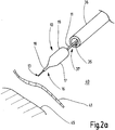
- FIG 2a shows an embodiment of an inventive Instruments 10, for example the instrument 10 according to the invention as in connection with Figure 1a and 1b described, the shaft 11 is guided through a working channel 35 of an endoscope 36 and the working tip 13 and recovery element 17 is arranged in front of the distal end 37 of the endoscope 36.
- the endoscope 36 is inserted through the esophagus into the patient's stomach 40 and arranged with the working tip 13 in front of the patient's stomach wall 41.
- the aim is to use the instrument 10 to obtain a biopsy 20 from the patient's pancreas 45, which is adjacent to the stomach 40.
- the instrument 10 is advanced in the piercing or advancing direction VR in the direction of the stomach wall 41 and by means of the working tip the stomach wall 41 is pierced, that is to say an opening 46 is created in the stomach wall 41, as shown in FIG Figure 2c is illustrated.
- the instrument 10 is pushed further through the opening 46 thus created in the stomach wall 41, the part 19 of the recovery element 17 also being pushed through the opening 46 to surround the biopsy 20.
- the mountain element 17 is squeezed radially.
- the wall of the mountain element 17, in particular the wall of the part 19 for surrounding the biopsy 20, preferably has a thickness of 0.005 mm up to and including 2 mm.
- the wall, in particular the wall of the part 19 for surrounding the biopsy 20, preferably has a thickness of ⁇ 0.5 mm.
- the maximum thickness of the wall of the mountain element 17 or at least the maximum thickness of the part 19 which surrounds the biopsy 20 is between 0.005 mm up to and including 2 mm or less than 0.5 mm, the implementation through an organ wall, such as the stomach wall 41, is thereby facilitated.
- a sub-section 30 of part 19 adjoining the fastening section 18 for surrounding the biopsy 20 is tapered, in particular conically tapered, in the advancing direction VR, the pushing of the recovery element 17 through the opening 46 in the stomach wall 41 can be facilitated.
- the subsection 30, which connects the section 31 for surrounding the biopsy 20 to the fastening section 18, can have an outer diameter da1 at the transition to the section 31 of the recovery element 17 for surrounding the biopsy 20 (see by way of example) Figure 7 ), which to the outer diameter da2 at the transition to the fastening section 18 in a ratio of at most 1: 1 to at least 1: 6; is preferably at most 1: 3 to at least 1: 5 if the mountain element 17 is not elastically deformed transversely to the longitudinal direction of the shaft 11.
- the indication of the ratio can relate to a position in which the free end 27 of the recovery element 17 points in the proximal direction and / or to a position in which the free end 27 of the recovery element 17 points in the distal direction.
- the subsection 30 is preferably not connected directly to the shaft 11 or the working tip 13, but via the fastening section 18 to the instrument 10.
- the subsection 30 is preferably elastically deformable radially or transversely to the withdrawal direction ZR and / or the piercing direction VR. If subsection 30 has emerged from the opening 46 between the stomach wall and the pancreas, it can return to its original shape due to its elasticity.
- the mountain element 17 can be pulled through the opening 46 in the course of the movement Piercing the gastric wall 41 is lengthened and in particular stretched because rear sections of part 19 of the recovery element 17 pass through opening 46 more slowly than front sections which have already passed through opening 46 are advanced.
- the recovery element 17 and / or the part 19 of the recovery element which adjoins the fastening section 18 is preferably elastically stretched to five times the unstretched length, particularly preferably to at most 1.5 times the unstretched length of the recovery element 17 or the part 19. The length is preferably measured in the longitudinal direction of the biopsy instrument 10 and / or the working tip 13.
- tissue biopsies directly behind the stomach wall 41 can also be obtained without foregoing the surrounding of the biopsy 20 by the mountain element 17 when withdrawing through the opening 46 have to.
- the instrument 10 is pushed further through the opening 46 and when the mountain element 17 has left the opening 46 between the stomach wall 41 and the pancreas 45, elastic sections 30 of the mountain element 17, if present, can return to their original shape due to radial expansion accept again.
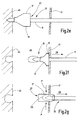
- the instrument 10 is advanced further until the working tip 13 presses against the tissue of the pancreas 45 or is inserted into the tissue of the pancreas 45 ( Figure 2e ).
- the working tip 13 is cooled and as a result tissue is frozen to the working tip 13.
- the tissue is removed by suddenly pulling back the instrument 10 in the mountain direction ZR (arrow in Figure 2f ) from the pancreas 45.
- the working tip 13 is pulled out of the space between the pancreas 45 and the stomach wall 41 through the opening 46.
- the mountain element 17 comes into contact and / or engagement with the stomach wall 41 beforehand and is put over the working tip 13 or the biopsy 20 by the retracting movement of the shaft 11 and the contact with the stomach wall 41 or the engagement with the stomach wall 41 to do this as shown by arrows P in Figure 2g is illustrated to shield ZR across the mountain direction, in particular when pulling through the gastric wall 41 (see in particular Figure 2h ).
- the mountain element 17 can be structured 47 (see example Figure 3b ), which is set up to engage the edge of the opening 46 or the stomach wall 41 around the opening 46 when the working tip 13 is withdrawn, in order to support the turning of the recovery element 17 around the biopsy 20.
- the structuring can, for example, consist of a rough surface and / or the internal surface structuring can have scales and / or knobs, so that the structuring engages with the stomach wall 41 or the edge of the opening 46 when it is pulled back and remains there, so that the Recovery element 17 is turned inside out by pulling back. Pulling through the mountain element 17 through the opening 46 in the stomach wall 41, with the part 19 of the recovery element 17 being turned inside out to surround the biopsy 20, can be facilitated if the undeveloped subsection 30 of the part 19 adjacent to the fastening section 18 for surrounding the biopsy 20 is located on the outside in the mountain direction ZR (Retraction direction) is tapered when the outer diameter decreases conically in the up and down direction ZR, for example.
- ZR Retraction direction
- the recovery element 17 can be designed to surround the biopsy 20 circumferentially, along a circumference around the working tip 13, in order to fluidically separate the biopsy 20 from the tissue, in particular the stomach wall tissue. If the biopsy 20 is fluidically separated from the tissue by means of the mountain element 17 transversely, in particular perpendicularly to the direction of withdrawal (RZ), the biopsy 20 and tissue can be protected particularly reliably against mutual contamination.
- the section of the mountain element which surrounds the biopsy is accordingly preferably liquid-tight, in particular made of liquid-tight material. If the mountain element 17 forms a liquid-tight jacket or screen transversely to the direction of retraction ZR, this can hold the biopsy 20, particularly when it is pulled through the opening 46 ( Figures 2g .
- the inverted mountain element preferably surrounds the biopsy in such a way that no liquid and / or aerosol and / or gas can get to the biopsy or from the biopsy to the environment transversely to the mountain direction and / or radially to the working tip and / or the shaft the mountain element is in the direction opposite to the mountain direction, especially in the direction in which the working tip points open in exemplary embodiments.
- FIG 2h illustrates how the mountain element is squeezed together as it is pulled through the opening.
- the mountain element placed over the biopsy supports that the biopsy does not get caught on the edge of the opening when it is pulled through the wall, so that the biopsy is not stripped from the working tip when it is pulled through the opening in the organ wall.
- the recovery element preferably consists of a material or preferably has a coating, which material or coating is set up to adhere and / or freeze the recovery element to the instrument, for example a cryobiopsy probe, in particular at its working tip, and / or to freeze and / or to prevent the biopsy from sticking to the mountain element.
- the recovery element can be made of plastic, for example, PTFE or silicone.
- the surface of the mountain element (the first surface and / or the second surface) preferably has a non-stick coating against the adhesion of cells and / or tissue.
- Figure 2i shows that even after pulling through the stomach wall, after the recovery element and the working tip have left the opening, the recovery element is turned inside out and shields the biopsy in the radial direction.
- the mountain element surrounds the biopsy in a closed manner, the biopsy is neither contaminated with gastric wall cells or germs from the gastric wall, nor has the biopsy touched the inner wall of the stomach when it was pulled through the opening, so that cells, in particular degenerate cells, or germs from the biopsy in the stomach wall would be left.
- the inverted mountain element 17 can also protect the biopsy 20 against unwanted stripping on the distal end 37 of the endoscope 36 or in the working channel 35 of the endoscope 36 if the working tip 13 with the biopsy 20 is pulled back into the working channel 35 of the endoscope 36, for example to recover the biopsy 20 through the working channel 35.
- the recovery element can completely enclose the biopsy, that is, not only surround it circumferentially, but the inverted recovery element, possibly together with the instrument, can enclose the biopsy on all sides.
- a region of the part of the everted mountain element for surrounding the biopsy can also be arranged distally between the distal end of the working tip and the surroundings.
- the recovery element is preferably so long that the inverted recovery element extends over the distal end of the working tip and / or over the distal end of the biopsy.
- the free end 27 of the mountain element 17 can be set up to be knotted together when pulled through the opening 46 by the elastically deformed tissue of the stomach wall 41 which surrounds the opening 46 and held together by adhesive forces in order to largely close the end 27 ,
- the biopsy 20 can are completely encased in this way, that is to say they are also separated from the surroundings in the distal direction (in the advancing direction VR) by means of the mountain element 17. If the biopsy 20 is completely enveloped by the everted mountain element 17, the spread of germs can be prevented particularly effectively.
- the fastening section 18 can be glued or clamped to the shaft of the instrument 10, for example.
- the recovery element 17 is preferably attached to the instrument 10 in a fluid-tight manner.
- the attachment section 18 is adjoined at a connection point 50 by the part 19 of the recovery element 17, which is turned inside out and which radially shields the biopsy 20.
- the connection point 50 is arranged proximally on the fastening section 18.
- the connection point 50 is arranged distally on the fastening section 18.
- the according Figure 3 Modified fixation of the recovery element 17 can improve the everting properties of the recovery element 17, since the part of the recovery element 17 does not have to be pulled over the fastening section 18 to shield the biopsy 20 when inverting.
- Figure 3b shows the mounting position or the orientation of the recovery element that is turned inside out through the opening 46 in the organ wall 417.
- the mountain element can have a funnel shape, wherein the funnel neck can form the fastening section 18.
- the mountain element 17 can be pulled or pushed onto the shaft 11, the shaft 11 passing through the funnel neck.
- Figure 3a shows the orientation for insertion into the organ wall 41 (see, for example, Figures 2a to 2i ) to get to the place where the biopsy should be taken.
- the mountain element 17 can initially in the assembly position or orientation ( Figure 3b ) and then in the orientation for piercing as in Figure 3a shown upside down.
- the recovery element 17 When the recovery element is pulled back through the opening 46 after the tissue sample has been taken up, the recovery element 17 is turned back over the working tip 13 in the distal direction VR into the orientation shown in FIG Figure 3b is illustrated.
- the mountain element 17 is (this also applies, for example, to the mountain element 17 according to FIG Figure 1a, 1b ) can be turned inside out both in the distal direction VR and in the proximal direction ZR.
- Figure 3c shows an image of a modification of the embodiment according to Figures 3a, b as it can also be present in the other described embodiments.
- the part 19 of the mountain element 17 has a structuring 58 on its first surface 25 for surrounding the biopsy to be removed, which surface is initially oriented outwards and which is turned inwards when the biopsy is recovered by turning the mountain element 17 inside out.
- the instrument 10 is in Figure 3d in a position, which position is represented on the one hand by the position of the instrument 10 Figure 2d corresponds, since the working tip 13 is located between the stomach wall 41 and the pancreas 45 and the part 19 of the recovery element for surrounding a biopsy is arranged in the opening 46.
- the working tip 13 is pressed against the tissue of the pancreas 45 or, as is also the case Figure 2e shows, stabbed into the tissue of the pancreas 45. If the instrument 10 from the described and in Figure 3d position is withdrawn without being able to push the instrument 10 further in advance in the VR direction in such a way that the part 19 of the recovery element 17 reaches between the stomach wall 41 and the pancreas 45, the structuring is achieved 58 with the stomach wall at the latest when pulling back into positive and / or frictional engagement. As a result, an inverting of the mountain element 17 is promoted when retracting in the mountain direction ZR.
- the structuring 58 can be formed, for example, by a rough surface and / or the structuring 58 can be formed by at least one or more structural elements, such as scales, for example, which can form barbs and / or knobs.
- the structuring 58 offers an advantage in particular if the target area from which the biopsy specimen is to be obtained is so close behind the stomach wall 41 or another organ wall that the working tip 13 is already in or on the tissue of the pancreas 45 or of another organ, while the part 19 of the mountain element 17 for surrounding in a Figure 3d corresponding position, that is, it has not yet completely passed through the opening 46.
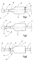
- FIG 4 shows a further exemplary embodiment of an instrument 10 according to the invention.
- An elastic, for example circular or polygonal, ring 51 is formed at the free end of the everting section of the recovery element and forms a support element.
- the ring 51 has a larger inner diameter than the opening 46 in the organ wall 41 (see below Figures 2a to 2i which show the creation of the opening 46 in the organ wall 41 and the recovery of the biopsy 20 through the opening 46).
- the ring 51 is squeezed to fit through the opening 46.
- the ring 51 When the ring 51 has left the opening 46 on the other side of the organ wall 41, the ring 51 relaxes again due to its elasticity, that is to say, due to the elasticity, the outer diameter outside the opening 46 has a larger diameter transverse to the direction of advance VR and / or take its original form.
- the recovery element 17 When pulling back, the recovery element 17 is supported by the ring 51 around the opening 46 radially spaced from the opening 46 on the organ wall 41 and thus promotes the inverting of the recovery element 17.
- the support element 51 is preferably arranged at the end 27 of the recovery element 17, so that when the instrument 10 is withdrawn through the opening 46 with the biopsy 20 obtained, the support element 51 only passes through the opening 46 in the organ wall 41 after the biopsy 20, shielded by means of the recovery element 17, has entered the opening 46 or the opening 46 in has left the organ wall 41.
- the support element 51 is preferably set up to at least preferably support itself on the organ wall 46 when withdrawing until the recovery element 17 has been turned inside out.
- the diameter of the opening 28 at the end 27 of the mountain element 17, which opening 28 can be formed by the ring 51 as in the illustrated exemplary embodiment, can preferably be smaller than the inner diameter of the mountain space 53.
- Figure 5 shows an embodiment of the instrument 10 according to the invention, which has cutting elements 54 arranged on the working tip 13, which show the feasibility through the organ wall to the point at which improve the biopsy20.
- FIG. 6 shows a further exemplary embodiment of an instrument 10 according to the invention, in which the fastening section 18 is enclosed by means of a fastening ring 56 and is clamped (crimped) on the shaft 11 in order to transition from the shaft diameter or the diameter of the working tip to the diameter of the fastening section 18 or of the fastening ring 56, a shaped element 57 is arranged between the working tip 13 and the fastening section 18 with an outer diameter widening in the direction of the fastening section 18, for example a conically widening outer diameter. This shaped element 57 facilitates the passage of the instrument 10 through the opening in the organ wall, at least in the piercing direction.
- the biopsy recovery device can, however, also be used with other biopsy probes in order to separate a biopsy from the environment during the removal, in order to protect the environment or the biopsy or to prevent the biopsy being lost.
- the biopsy recovery device can also be used on a biosia probe with which a biopsy is punched out of the tissue.
- the mountain element is essentially designed as a one-piece part or flexible sleeve, in particular as a seamless one-piece part
- the mountain element can also consist of several parts which are connected to one another to form a mechanical element.
- the mountain element can be constructed similar to a bellows.
- the stiffness of the different sections of the mountain element can be influenced in a targeted manner by the dimensional configuration of the mountain element and / or different materials for different sections of the mountain element.
- Figure 7 shows an embodiment of a biopsy instrument 10 with a working tip 13 with an area 60 which is intended to adhere the biopsy.
- the region 60 has a largest diameter d2, which is smaller than the diameter d3 of the shaft 11 measured at a point on or in the mountain element 17.
- the ratio of the diameter d3 of the shaft 11 - at one Measured in place on or in the mountain element 17 - to the largest outer diameter d4 of the mountain element is 1: 1.
- the ratio is greater than 1: 1.
- the ratio is preferably at most 1: 1 to at least 1: 6, particularly preferably at most 1: 3 to at least 1: 5.
- Figure 8 shows on the basis of a further exemplary embodiment that the length 1 of the section of the instrument 10, which is intended for receiving, in particular by adhering, a biopsy 20 and along which the part 19 of the recovery element 17 extends when surrounding the biopsy 20 and thus separates the section , preferably 2 to 20 times, particularly preferably 4 to 10 times, the diameter d3 of the shaft 11 measured at a point on or in the recovery element 17.
- Figure 8 illustrates a mountain element that envelops a biopsy, outside the patient's body, where no forces act on the mountain element from the outside, which would compress the mountain element.
- the section 31 of the recovery element 17 for surrounding the biopsy 20 can be flexible such that the section 31, when the section 31 is pressed against the biopsy 20 when the working tip 13 is pulled out of the patient's body, adapts and adapts to the biopsy 20 remains clinging to the biopsy 20 when the working tip 13 is pulled out of the body and thus the external force has ceased due to the resistance of the patient's tissue against deformation, which force presses the section 31 against the biopsy 20 when it is pulled out.
- the material or materials of the mountain element can have hardnesses of at least 20 to at most 80 Shore A, preferably at least 40 to at most 60 Shore A.
- the mountain element can be composed of materials, for example different silicones, which have different hardnesses. The hardness can decrease in the longitudinal direction L of the recovery element in the direction of the free end 27 of the recovery element 17, for example, be greater in the connecting section 30 than in the section 31 for surrounding the biopsy 20.
- Figure 8 shows an embodiment of a mountain element, which may have, for example, a harder material in the fastening section of the mountain element than in the connecting section 30 of the mountain element 17 adjacent to the free end 27 of the mountain element 17, which also includes the section 31 of the mountain element 17 for surrounding the biopsy 20 connects the attachment portion 18.
- the material of the connecting section 30 can be harder than the material of the section 31 of the mountain element 17 for surrounding the biopsy 20.
- the difference in hardness between the materials can be at least 5 Shore A, for example.
- the hardness of the sections may increase linearly, progressively or degressively from the section 31 for surrounding as the least hard section, via the connecting section 30 to the fastening section 18 as the hardest of the three sections 18, 30, 31.
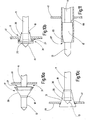
- Figure 9 uses an exemplary embodiment to illustrate that embodiments of the mountain element 17 can have a clamping structure 61.
- the recovery element 17 can have a clamping structure 61 which has elongate elements and / or sections 63 which extend from a base section or element 62 and are spaced apart from one another in the circumferential direction U and which, due to the rigidity of the connections of the base section or element 62 with the elements and / or sections 63 extending from this path, when an external force is lost, they endeavor to return to their original orientation with respect to the base section or element 62 and thus to clamp the clamping structure 61 after, for example, the base section and / or element 62 has been moved through a narrow opening 46 of a fabric wall into another area.
- the circumferentially spaced elongated elements or sections 63 ensure that the subsection 30 can be compressed radially in a controlled manner when the subsection 30 is pushed through an opening 46 in a fabric wall, and the connection to the base section or element 62 for this purpose, that the subsection 30 opens again particularly reliably due to the elastic restoring forces in order to return to its original shape.
- Figures 9a and 9b illustrate that the mountain element 17 elongate sections 63 can be formed, for example, in the form of a wall thickness which increases and decreases alternately along the circumferential direction and / or can have elongated reinforcing element sections 63 which can be made of a different material than the subsection 30, for example made of metal or another polymer ,
- the areas of different wall thicknesses can be formed together from the same material and / or the same or different material as a thickening is applied to a base material of the mountain element 17 in elongated areas.
- the elongated sections 63 can extend into the section 31 for surrounding the biopsy or end in the connecting section 30 before the section 31.
- the section 31 of the recovery element 17 for surrounding the biopsy 20 for the insertion of the biopsy instrument for its positioning can be received in the connection section 30 of the recovery element 17.
- the section 30 for surrounding the biopsy 20 can preferably be rolled and / or folded into the connecting section 30.
- Figure 10a shows an example of a biopsy instrument 10 after piercing an organ wall 41 for positioning.
- the free end 27 of the recovery element or the opening in the connecting section 30 points away from the distal end of the working tip 13.
- the section 31 of the recovery element 17 at the free end 27 is folded into the connecting section 30. This prevents the mountain element 17 from being pulled too far proximally during insertion or insertion.
- the folded and / or rolled-up area forms a ring with a relatively high resistance to radial deformation, which promotes tensioning after piercing the wall 41.
- the mountain element is essentially turned up to the fastening section and the ring, which is created by folding and / or rolling, is turned outwards.
- the section 31 for surrounding the biopsy 20 is automatically unfolded and thereby pulled over the biopsy ( Figure 10c ).
- Biopsy instruments 10 can have a securing element 65, which is set up to prevent unwanted turning of the mountain element 17 during the positioning of the working tip 13 in order to separate the biopsy 20.
- the securing element 65 can be deactivated, so that it is possible to turn it inside out when withdrawing.
- the securing element 65 can enclose the mountain element 17, for example, and thus prevent it from being turned inside out.
- the securing element 65 can be peelable from the recovery element 17, while the working tip 13 is positioned in the tissue in order to release the everting.
- the securing element 65 preferably encloses an edge 66 of the recovery element 17 pointing in the proximal direction, which edge extends from the free end 27 or, for example, by rolling and / or folding, as in connection with the exemplary embodiment according to FIG Figures 10a to 10c described, formed ring be formed. This is because the edge 66 is intended to come into engagement with the fabric wall 41 in such a way that the mountain element 17 is turned inside out.
- the securing element 65 can be connected to the biopsy instrument 10 and / or the recovery element 17, the connection 67 having to be released in order to cancel the securing.
- the connection can be set up to have to be destroyed when detached.
- connection can be set up to be dissolved or at least weakened when in contact with liquid, in particular tissue fluid, so that the securing element 65 can be released from the recovery element 17 or the biopsy instrument 10.
- Figure 11 shows an embodiment of a securing element 65 in the form of an envelope tube.
- the enveloping tube 65 can, for example, be selectively connected to the mountain element 17 with a connection 67 that can be destroyed with little force, or loosely surround the mountain element 17.
- the length of the enveloping tube 65 is preferably dimensioned such that when the working tip 13 is positioned, the enveloping tube 65 extends at least over the edge 66 of the mountain element 17 or even at least through the opening 46 in the fabric wall 41.
- the securing element 65 is set up so that the operator, after reaching the end position of the biopsy instrument 10 (position for the biopsy specimen is removed) and before withdrawing the working tip 13 with the biopsy specimen, can withdraw the sheath tube 65 in the proximal direction from the recovery element 17 , possibly by destroying a connection 67 of the securing element 65 to the recovery element 65 or another section of the biopsy instrument 10.
- Figure 12 illustrates using an exemplary embodiment of a recovery element 17 according to the invention with a decreasing wall thickness in the direction of the free end 27 of the recovery element.
- the greatest wall thickness wv of the connecting section 30 can be greater than the greatest wall thickness wu of the section 31 for surrounding the biopsy.
- the greatest wall thickness wb of the fastening section 18 can be greater than the greatest wall thickness wv of the connecting section 30.
- the greatest wall thickness wv one elongated section 63 or the greatest wall thickness between two adjacent elongated sections 63 may be greater than the greatest wall thickness wb of the section 31 for surrounding the biopsy and / or less than the greatest wall thickness wb of the fastening section 18.
- the greatest wall thickness may be if the sections 63 of the clamping structure 61 extend into the section 31 for surrounding the biopsy 20, for example outside the elongated sections 63.
- the wall thickness of the mountain element can decrease (continuously) from a section adjacent to the free end 27, for example from the connecting section 30 to the section 31 for surrounding.
- the wall thickness can, for example, decrease linearly in the direction of the free end 27.
- the wall thicknesses averaged over the lengths of the individual sections can be compared, the average wall thickness decreasing, for example, in the direction of the free end 27 of the mountain element 17.
- FIG. 1 A perspective view of an exemplary embodiment of a clamping structure 65
- FIG. 1 A perspective view of an exemplary embodiment of a clamping structure 65
- FIG. 1 A perspective view of an exemplary embodiment of a clamping structure 65
- FIG. 1 A perspective view of an exemplary embodiment of a clamping structure 65
- FIG. 1 A perspective view of an exemplary embodiment of a clamping structure 65
- FIG. 1 A perspective view of an exemplary embodiment of a clamping structure 65
- FIG. 1 A perspective view of an exemplary embodiment of a clamping structure 65
- FIG. 1 A perspective view of an exemplary embodiment of a clamping structure 65
- FIG. 1 A perspective view of an exemplary embodiment of a clamping structure 65
- FIG. 1 A perspective view of an exemplary embodiment of a clamping structure 65
- FIG. 1 A perspective view of an exemplary embodiment of a clamping structure 65
- a biopsy recovery device 16 is provided for recovering a biopsy 20 through an opening 46 with a recovery element 17 for attachment to or adjacent to a working tip 13 of a biopsy instrument 10, wherein the recovery element 17 is designed to pull the working tip 13 back through the opening 46 over the Biopsy 20 to be turned inside out to surround the biopsy 20 when the working tip 13 is withdrawn through the opening 46 in order to separate the biopsy 20 from the surroundings when it is withdrawn through the opening 46.
- the biopsy 20 and / or the environment can be protected against contamination and / or cell carry-over and / or germ carry-over and / or the biopsy 20 can be protected against unintentional stripping of the biopsy 20 at the opening 46.
Landscapes
- Health & Medical Sciences (AREA)
- Life Sciences & Earth Sciences (AREA)
- Surgery (AREA)
- Biomedical Technology (AREA)
- General Health & Medical Sciences (AREA)
- Heart & Thoracic Surgery (AREA)
- Medical Informatics (AREA)
- Molecular Biology (AREA)
- Pathology (AREA)
- Animal Behavior & Ethology (AREA)
- Engineering & Computer Science (AREA)
- Public Health (AREA)
- Veterinary Medicine (AREA)
- Nuclear Medicine, Radiotherapy & Molecular Imaging (AREA)
- Radiology & Medical Imaging (AREA)
- Biodiversity & Conservation Biology (AREA)
- Surgical Instruments (AREA)
- Sampling And Sample Adjustment (AREA)
- Endoscopes (AREA)
Abstract
Description
- Die Erfindung betrifft ein Biopsieinstrument.
- Aus
DE 10 2007 020 582 A1 ist ein kryochirurgisches Instrument und Verfahren zum Abtrennen einer Gewebeprobe bekannt, welches Instrument eine Sonde mit einem Sondenkopf zum Festfrieren einer Probe aufweist sowie eine Stützeinrichtung aufweist, in der die Sonde geführt ist. Mittels der Stützeinrichtung ist das umliegende Gewebe während des Abtrennens der Gewebeprobe abstützbar. Der Sondenkopf kann beim Abreißen der festgefrorenen Gewebeprobe in die Stützeinrichtung zurückgezogen werden, so dass die Gewebeprobe dadurch sicher in der Stützeinrichtung untergebracht ist. - Aus
DE 10 2008 026 635 A1 ist eine Kryobiopsiesonde bekannt, welche durch einen Stützschlauch führbar ist. Der Stützschlauch und die Sonde können relativ zueinander beschleunigt werden, um die Gewebeprobe mit einer definierten Abrisskraft abzureißen. - Bei der flexiblen endoskopischen Gewebeprobeentnahme (z.B. Gewebeprobe aus dem Pankreas) mit Hilfe einer Kryobiopsiesonde durch eine Organwand (z.B. Magenwand) hindurch können Teile der Probe oder die gesamte Probe während des gesamten Bergewegs oder speziell beim Durchziehen durch die Organwand verloren gehen. Dadurch kann es zur Keim- oder Zellverschleppung kommen.
- Zur Bergung von Gewebeproben ist es bekannt, einen Bergeschlauch mit einem Bergebereich vorzusehen, wobei die Sonde mit der Gewebeprobe in den Bergebereich eingezogen wird. Die Sonde wird mit dem Bergeschlauch gleichzeitig entfernt. Der Bergeschlauch der Kryopunktionssonde kann jedoch nicht durch die entsprechende Organwand mit hindurchgeführt werden. Denn der Bergeschlauch hat einen zu großen Durchmesser und dadurch ist ein zu hoher Kraftaufwand nötig, um den Bergeschlauch vorzuschieben. Die Gefahr eines Abstreifens der Probe an der Organwand besteht somit weiterhin. Die Gewebeprobe (z.B. Tumorgewebe) wird durch gesundes Gewebe (z.B. Magenwand) hindurchgezogen, bevor diese in den Bergeschlauch eingezogen wird. Dabei können Tumorzellen verschleppt werden. Es kann zum Verlust von Gewebeproben durch Abstreifen an z.B. der Magenwand kommen.
- Aus dem Stand der Technik ist außerdem die Stanzbiopsie bekannt, bei welcher mittels spezieller Nadeltypen (z.B. TruCut) ein zylinderförmiges Biopsat gewonnen werden kann. Dieses ist jedoch oft mit Artefakten behaftet und die Biopsatmenge kann für eine Auswertung zu gering sein.
- Aus dem Stand der Technik ist zudem die Feinnadel-Biopsie bekannt, bei der eine Injektionsnadel in die Gewebestelle eingeführt wird, aus der eine Probe entnommen werden soll und Zellen durch die Injektionsnadel abgesaugt werden. Größere Biopsate können damit nicht gewonnen werden.
- Aufgabe der Erfindung ist ein verbessertes Konzept zur Gewinnung eines Biopsats anzugeben.
- Diese Aufgabe wird mit einer Biopsatbergeeinrichtung nach Anspruch 1 und einem Biopsieinstrument nach Anspruch 11 gelöst:
Die erfindungsgemäße Biopsatbergeeinrichtung weist ein Bergeelement zum Befestigen an oder benachbart einer Arbeitsspitze eines Biopsieinstruments (im Folgenden auch Instrument genannt) auf. Die Arbeitsspitze ist dazu eingerichtet, das Biopsat festzuhalten. Die Arbeitsspitze kann auch als Kopf oder Sondenkopf bezeichnet werden. Das Biopsat kann beispielsweise außen an der Arbeitsspitze anhaften, insbesondere angefroren sein, und/oder in der Arbeitsspitze aufgenommen sein. Die Arbeitsspitze kann dazu eingerichtet sein, durch eine Öffnung, insbesondere in einer Gewebewand, zu einem Entnahmeort, beispielsweise einer weiteren Gewebewand hinter der Gewebewand geführt zu werden. Beispielsweise kann die Arbeitsspitze dazu eingerichtet sein, durch eine Magenwand geführt zu werden, um in einem dem Magen benachbarten Organ, z.B. der Pankreas, ein Biopsat zu gewinnen. Die Arbeitsspitze ist dazu eingerichtet, durch eine Öffnung, z.B. durch eine Öffnung in einer Wand aus Gewebe, z. B. einer Organwand oder durch eine Öffnung eines Arbeitskanals eines Endoskops oder Bronchoskops zurückgezogen zu werden. Das Bergeelement ist dazu eingerichtet, beim Zurückziehen der Arbeitsspitze über das Biopsat umgestülpt zu werden, um das Biopsat bei dem Zurückziehen der Arbeitsspitze durch die Öffnung, beispielsweise durch die Organwand, zu umgeben, um das Biopsat beim Zurückziehen durch die Öffnung von der Umgebung, insbesondere quer zur Bergerichtung, insbesondere von der Wand um die Öffnung, zu separieren. Insbesondere kann das Biopsat mittels des Bergeelements beim Zurückziehen des Biopsats durch die Öffnung, insbesondere durch die Öffnung in der Gewebewand, von dem Rand der Öffnung oder der Gewebewand oder dem Gewebe separiert, also auf Abstand zu oder getrennt von dem Rand der Öffnung oder der Gewebewand oder dem Gewebe gehalten werden, beispielsweise um das Biopsat nicht zu verunreinigen. Die Bergeeinrichtung kann zusätzlich oder alternativ dazu dienen, das Gewebe um die Öffnung herum von dem Biopsat, welches Keime oder entartete Zellen enthalten kann, zu separieren, also das Biopsat auf Abstand zu oder getrennt von dem Gewebe zu halten, beispielsweise um die Keime oder entartete Zellen nicht zu verschleppen. - Das Bergeelement wird beim Zurückziehen vorzugsweise von einer ersten Stellung (Orientierung) in eine zweite Stellung (Orientierung) umgestülpt, um das Biopsat zu umgeben. Das Bergeelement weist vorzugsweise eine erste Oberfläche auf, welche beim Bergen, wenn das Bergeelement das Biopsat separiert, dem Biopsat zugewandt ist, und eine zweite Oberfläche auf, welche beim Bergen, wenn das Bergeelement das Biopsat separiert, vom Biopsat abgewandt ist. Beim Umstülpen von der ersten Stellung in die zweite Stellung zum Umgeben des Biopsats, wird die erste Oberfläche, welche in der ersten Stellung nach außen gekehrt ist, durch das Umstülpen nach innen gekehrt, um dem Biopsat zugewendet zu werden. Die zweite Oberfläche wird beim Umstülpen entsprechend nach Außen gekehrt.
- Mittels des Bergeelements kann das Biopsat und/oder das Gewebe um die Öffnung nicht nur vor Keim- oder Zellverschleppung geschützt werden, sondern das Biopsat kann mittels des Bergeelements auch vor einem mechanischen Abstreifen des Biopsats beim Durchziehen durch die Öffnung geschützt werden. Dies ist insbesondere für Ausführungsformen erfindungsgemäßer Biopsieinstrumente von Bedeutung, mit welchen Biopsate gewonnen werden können, die eine Querabmessung, z.B. Durchmesser, aufweisen, die größer als die Querabmessung der Arbeitsspitze und/oder eines mit der Arbeitsspitze geschaffenen Stichkanals in das Zielgewebe und/oder einer mit der Arbeitsspitze geschaffenen Öffnung in einer Organwand ist.
- Es wird zudem ein Biopsieinstrument angegeben, welches eine erfindungsgemäße Biopsatbergeeinrichtung aufweist.
- Die erfindungsgemäße Biopsatbergeeinrichtung und/oder das erfindungsgemäße Biopsieinstrument können mit einem oder mehreren der folgenden Merkmale weitergebildet sein:
- Wenn das Bergeelement über das Biopsat gestülpt ist, um das Biopsat umfänglich zu umgeben, kann das Biopsat durch das Bergeelement einen mechanischen Schutz erfahren, beispielsweise gegen Abstreifen von der Arbeitsspitze. Das Bergeelement kann dazu eingerichtet sein, das Biopsat umfänglich, insbesondere entlang des Umfangs um den Schaft, an welchem die Arbeitsspitze angeordnet ist, entlang eines Umfangs um die Arbeitsspitze und/oder um das Biopsat, geschlossen zu umgeben, um das Biopsat fluidisch von dem Gewebe zu separieren. Wenn das Biopsat von dem Gewebe mittels des Bergeelements quer, insbesondere senkrecht zur Zurückziehrichtung von der Umgebung fluidisch separiert wird, können Biopsat und Gewebe besonders zuverlässig vor gegenseitiger Kontamination geschützt werden. Der Abschnitt des Bergeelements, welcher das Biopsat umgibt, ist vorzugsweise flüssigkeitsdicht, insbesondere aus flüssigkeitsdichtem Material. Der Abschnitt kann beispielsweise aus Kunststoff sein, beispielsweise aus Silikon oder Polytetrafluorethylen bestehen. Wenn das Bergeelement dazu eingerichtet ist, einen flüssigkeitsdichten Schirm oder Mantel für das Biopsat zu bilden, kann das Bergeelement das Biopsats besonders effektiv gegen Kontamination durch Flüssigkeit abschirmen, insbesondere beim Bergen des Biopsats durch eine enge Öffnung in einer Gewebewand, welche Gewebewand um die Öffnung das Biopsat ohne Bergeelement beim Bergen direkt berühren würde.
- Das Bergeelement kann dazu eingerichtet sein, im elastisch nicht verformten Zustand quer zur Zurückziehrichtung oder Bergerichtung bzw. quer zur Längserstreckungsrichtung des Schaftes und/oder der Arbeitsspitze das Biopsat mit Abstand zu umgeben. Der Bergeraum, welchen das umgestülpte Bergeelement für das Biopsat schafft, kann in elastisch nicht verformten Zustand quer zur Bergerichtung einen Innendurchmesser aufweisen, welcher größer ist, als der Durchmesser des Biopsats.
- In Ausführungsformen kann ein Abschnitt des Bergeelements zum Umgeben des Biopsats derart nachgiebig sein, dass der Abschnitt, wenn der Abschnitt beim Herausziehen der Arbeitsspitze aus dem Körper des Patienten gegen das Biopsat gedrückt wird, sich an die Form des Biopsats anpasst und an dem Biopsat angeschmiegt bleibt, wenn die Arbeitsspitze aus dem Körper herausgezogen ist.
- Das Verhältnis des Durchmessers des Schaftes - an einer Stelle an oder in dem Bergelement gemessen - zu dem größten Außendurchmesser des Bergeelements ist vorzugsweise höchstens 1:1 bis wenigstens 1:6, besonders bevorzugt höchstens 1:3 bis wenigstens 1:5. Ein Verhältnis von 1:1 ist möglich, wenn der größte Durchmesser der Arbeitsspitze in deren Bereich zum Anhaften des Biopsats kleiner ist als der Durchmesser des Schaftes.
- Die Länge des Abschnitts des Instruments, welcher zur Aufnahme, insbesondere durch Anhaften, eines Biopsats bestimmt ist und entlang welchem sich der Teil des Bergeelements beim Umgeben des Biopsats erstreckt und damit den Abschnitt separiert, entspricht vorzugsweise dem 2 bis 20-fachen, besonders bevorzugt dem 4 bis 10-fachen, des Durchmessers des Schaftes gemessen an einer Stelle an oder in dem Bergeelement.
- Während das umgestülpte Bergeelement das Biopsat vorzugsweise umfänglich (entlang eines Umfangs um das Biopsat herum) derart umschließt, so das keine Flüssigkeit und/oder Aerosol und/oder Gas quer zur Bergerichtung und/oder radial zur Arbeitsspitze an das Biopsat gelangen kann oder von dem Biopsat in die Umgebung gelangen kann, kann das Bergeelement in Richtung entgegen der Bergerichtung, insbesondere in die Richtung, in welche die Arbeitsspitze weist, offen sein.
- Das Bergeelement kann das Biopsat vollständig einschließen, also nicht nur umfänglich umgeben, sondern ein Abschnitt des um das Biopsat umgestülpten Bergelemements kann auch in distale Richtung bzw. in Längserstreckungsrichtung der Arbeitsspitze und/oder des Instruments zwischen dem distalen Ende und der Umgebung angeordnet sein. Wenn das Biopsat von dem umgestülpten Bergeelement vollständig eingehüllt wird, kann eine Keimverschleppung besonders wirksam verhindert werden.
- Das Bergeelement kann eine Strukturierung aufweisen, welche dazu eingerichtet ist, beim Zurückziehen der Arbeitsspitze mit der Öffnung, dem Öffnungsrand und/oder der Wand um die Öffnung in Eingriff zu geraten, um das Umstülpen des Bergeelements um das Biopsat zu unterstützen. Die Strukturierung gerät beim Zurückziehen mit der Wand, dem Öffnungsrand und/oder der Öffnungswand in Eingriff und kann dort auf Grund von Formschluss oder Reibschluss vorübergehend hängen bleiben, so dass das Umstülpen des Bergeelements durch das Zurückziehen gefördert wird, bis der Abschnitt des Bergeelement mit der Strukturierung durch die Öffnung gezogen wird. Die Strukturierung kann beispielsweise in einer rauen Oberfläche bestehen oder die Oberflächeninnenstrukturierung kann wenigstens ein Strukturelement oder mehrere Strukturelemente wie Schuppen und/oder Noppen aufweisen. Eine zum Fördern des Umstülpens bestimmte Strukturierung kann beispielsweise an einer Seite eines Teils des Bergeelements ausgebildet sein, welche beim Zurückziehen des Bergeelements beim Umstülpen nach außen gekehrt wird, und/oder eine zum Fördern des Umstülpens bestimmte Strukturierung kann beispielsweise an einer Seite eines Teils des Bergeelements ausgebildet sein, welche beim Zurückziehen des Bergeelements beim Umstülpen nach innen gekehrt wird.
- Ausführungsformen der Biopsatbergeeinrichtung können beispielsweise Bergeelemente aufweisen, welche ein Abstützelement aufweisen. Dieses ist bevorzugt quer zur Zurückziehrichtung elastisch verformbar und dazu eingerichtet, sich beim Zurückziehen an der Wand an der Öffnung, bevorzugt um die Öffnung herum, abzustützen, um das Umstülpen zu fördern. Das Abstützelement wird beim Durchführen durch die Öffnung in Richtung zu der Stelle, an der das Biopsat entnommen werden soll, elastisch verformt und nach dem Durchtritt durch die Öffnung, welche durch das Durchführen des Instruments, insbesondere des Bergeelements gedehnt werden kann, nach Wegfall der äußeren Kraft außerhalb der Öffnung bestrebt ist, wieder einen größeren Durchmesser quer zur Öffnungsrichtung bzw. zur Bergerichtung (Zurückziehrichtung) anzunehmen. Das Abstützelement, das auf Grund elastischer Rückstellkräfte wieder eine größeren Durchmesser angenommen hat, vorzugsweise einen größeren Durchmesser als die Öffnung, stützt sich bei dem Zurückziehen an der Wand, welche die Öffnung enthält, ab, bleibt also dort vorrübergehend hängen, um die Umstülpung zu fördern. Bevorzugt stützt sich das Abstützelement beim Zurückziehen um die Öffnung herum ab.
- Das Abstützelement stützt sich beim Zurückziehen zumindest vorzugsweise solange ab, bis das Bergeelement umgestülpt ist.
- Das Abstützelement kann beispielsweise ein elastisch verformbarer Ring sein. Das Abstützelement ist bevorzugt an dem Ende des Bergeelement angeordnet, welches beim Durchtreten durch die Öffnung in die Richtung um ein Biopsat mit der Arbeitsspitze aufzunehmen die Öffnung als letztes verlässt.
- Das Bergeelement kann aus einem Material bestehen oder eine Beschichtung aufweisen, welches Material oder Beschichtung dazu eingerichtet ist, um ein Anhaften und/oder Anfrieren des Bergeelements an dem Instrument, beispielsweise einer Kryobiopsiesonde, insbesondere an deren Arbeitsspitze und/oder deren Schaft, und/oder um ein Anfrieren und/oder Anhaften des Biopsats an dem Bergeelement zu verhindern. Beispielsweise kann das Bergeelement aus einem Material bestehen oder eine Beschichtung aufweisen, welches Material oder Beschichtung dazu eingerichtet ist, um ein Anhaften und/oder Anfrieren des Bergeelements an einem Biopsieinstrument zum Gewinnen eines Biopsats, welches Biopsieinstrument mit einer erfindungsgemäßen Biopsatbergeeinrichtung ausgestattet ist, insbesondere ein Anhaften und/oder Anfrieren an dessen Arbeitsspitze und/oder dessen Schaft, zu verhindern.
- Wenn das Bergelement bei einer Kryobiobsiesonde verwendet wird, ist zusätzlich oder alternativ das Bergeelement bevorzugt aus einem Material gebildet, welches in seiner Elastizität nicht von der Kühlung der Arbeitsspitze und/oder des Schaftes beeinflusst wird. Insbesondere ist die Elastizität des Teils des Bergeelements, welcher umgestülpt wird, bevorzugt in den Temperaturbereichen temperaturunabhängig, in welchen der umstülpbare Teil bei der Gewinnung des Biopsats mittels einer Kryobiopsiesonde zumindest in Abschnitten des Teils eine Temperatur annehmen kann.
- Das Bergeelement kann insbesondere angrenzend oder benachbart zu einer Befestigungsstelle an dem Biopsieinstrument oder benachbart zu einem Befestigungsabschnitt des Bergeelements, welcher an dem Biopsieinstrument fixiert ist, einen Unterabschnitt mit sich entlang eines Längsabschnitts des Biopsieinstruments erweiterndem Außendurchmesser aufweisen. Der Unterabschnitt kann zwischen dem Unterabschnitt und dem Biosieinstrument im umgestülpten Zustand einen Bereich eines Bergeraumes begrenzen. Der Außendurchmesser des Unterabschnitts kann sich zum Durchführen des Biopsieinstruments durch eine Öffnung in einer Wand in einer Richtung erweitern, die der Richtung (Durchführrichtung), in welche das Biopsieinstrument zum Durchführen bewegt wird, entgegengesetzt ist bzw. sich in Durchführrichtung verjüngt, um das Durchführen durch die Öffnung zu vereinfachen. Bevorzugt verjüngt sich der Außendurchmesser des Unterabschnitts bei in der ersten Stellung angeordnetem Bergeelement in Bewegungsrichtung des Instruments zu der Stelle, an welcher das Biopsat entnommen werden soll, und/oder verjüngt sich der Außendurchmesser des Unterabschnitts bei in die zweite Stellung umgestülptem Bergeelement in die Bergerichtung, d.h. in die Richtung, in welche das Biopsieinstrument zum Entfernen der Arbeitsspitze mit dem Biopsat von der Stelle entfernt wird, an welcher das Biopsat entnommen wurde. Auf diese Weise kann das Durchführen des Bergeelements durch die Öffnung vereinfacht sein. Der Unterabschnitt kann sich beispielsweise konisch verjüngen. Der Unterabschnitt ist vorzugsweise elastisch in radialer Richtung bzw. quer zur Bergerichtung verformbar. Damit kann das Durchführen des Bergeelements durch die Öffnung in Durchstechrichtung und/oder das Zurückziehen des Bergeelements durch die Öffnung besonders vereinfacht sein.
- Der Unterabschnitt, welche den Abschnitt zum Umgeben des Biopsats mit dem Befestigungsabschnitt verbindet, kann am Übergang zu dem Abschnitt des Bergeelements zum Umgeben des Biopsats einen Außendurchmesser aufweisen, welcher zu dem Außendurchmesser am Übergang zu dem Befestigungsabschnitt in einem Verhältnis von höchstens 1:1 bis mindestens 1:6; vorzugsweise höchstens 1:3 bis mindestens 1:5 steht, wenn das Bergeelement quer zur Längserstreckungsrichtung des Schaftes nicht elastisch verformt ist. Die Angabe des Verhältnisses kann sich auf eine Stellung beziehen, in welcher das freie Ende des Bergeelements in proximale Richtung zeigt, und/oder auf eine Stellung, in welcher das freie Ende des Bergeelements in distale Richtung zeigt.
- Bevorzugt weist das Material oder weisen die Materialien des Bergeelements eine Härte von mindestens 20 bis höchstens 80 Shore A, vorzugsweise mindestens 40 bis höchstens 60 Shore A auf. In Ausführungsbeispielen kann das Bergeelement aus Materialien zusammengesetzt sein, welche unterschiedliche Härten gemessen beispielsweise in Shore A aufweisen. Das Bergelement kann beispielsweise in dem Befestigungsabschnitt des Bergeelements ein härteres Material aufweisen als in dem hin zu dem freien Ende des Bergelements angrenzenden Abschnitt (Verbindungsabschnitt) des Bergeelements, welcher den Abschnitt des Bergeelements zum Umgeben des Biopsats mit dem Befestigungsabschnitt verbindet. Alternativ oder zusätzlich kann das Material des Verbindungsabschnitts härter sein als das Material des Abschnitts des Bergelements zum Umgeben des Biopsats sein. Der Härteunterschied zwischen den Materialien kann beispielsweise wenigstens 5 Shore A betragen. In Ausführungsbeispielen kann beispielsweise die Härte der Abschnitte linear, progressiv oder degressiv von dem Abschnitt zum Umgeben als am wenigsten harten Abschnitt, über den Verbindungsabschnitt zu dem Befestigungsabschnitt als am härtesten der drei Abschnitte steigen.
- Das Bergeelement kann eine Aufspannstruktur aufweisen, welche sich von einem Basisabschnitt oder -element weg erstreckenden, voneinander in Umfangsrichtung beabstandete, längliche Elemente und/oder Abschnitte aufweist, welche auf Grund der Steifigkeit der Verbindung des Basisabschnitts- oder -elements mit den sich von diesen Weg erstreckenden Elementen und/oder Abschnitt bestrebt sind, bei Wegfall einer äußeren Kraft ihre ursprüngliche Orientierung in Bezug auf den Basisabschnitt - oder element wieder anzunehmen und so die Aufspannstruktur aufzuspannen, nachdem beispielsweise das Basiselement durch eine enge Öffnung in einen weiteren Bereich bewegt worden ist. Die voneinander in Umfangsrichtung beabstandeten länglichen Elemente oder - Abschnitte sorgen dafür, dass sich der Unterabschnitt radial kontrolliert zusammendrücken lässt, wenn der Unterabschnitt durch eine Öffnung in einer Gewebewand geschoben wird, und die Verbindung mit dem Basiselement oder - abschnitt dafür, dass sich der Unterabschnitt auf Grund der elastischen Rückstellkräfte besonders zuverlässig wieder öffnet, um seine ursprüngliche Form wieder anzunehmen. Das Bergeelement kann länglichen Abschnitte beispielsweise in Form einer entlang des Umfangs abwechselnd zu- und abnehmenden Wanddicke und/oder längliche verstärkende Elementabschnitten aufweisen, welche aus einem anderen Material bestehen können, als der Unterabschnitt, z.B. aus Metall oder einem anderen Polymer.
- Wenn das Bergeelement in beispielhaften Ausführungsformen in Längsrichtung aneinander gereihte, unterschiedliche Materialien aufweist, welche Abschnitte des Bergeelements bilden, können Abschnitte unterschiedlicher radialer Steifigkeit gebildet werden. In Ausführungsbeispielen kann ein Verbindungsabschnitt beispielsweise aus einem anderen Werkstoff bestehen als ein Abschnitt zum Umgeben des Biopsats. Damit können Ausführungsbeispiele des erfindungsgemäßen Bergeelements bereitgestellt werden, in welchen der Verbindungsabschnitt eine andere, z.B. größere, radiale Steifigkeit aufweisen kann als der Abschnitt zum Umgeben des Biopsats.
- Alternativ oder zusätzlich kann, in Ausführungsformen des Bergeelements, die größte Wanddicke des Abschnitts des Bergeelements zum Umgeben des Biopsats kleiner sein als die größte Wanddicke des Verbindungsabschnitts des Bergeelements, welcher den Abschnitt zum Umgeben des Bergeelements mit dem Befestigungsabschnitt verbindet. In Ausführungsformen mit einem Verbindungsabschnitt, dessen Wanddicke entlang des Umfangs abwechselnd zu- und abnimmt, z.B. um eine Aufspannstruktur zu bilden, kann die Wanddicke zum Vergleich mit der Wanddicke des Abschnitts zum Umgeben des Biopsats an einer Stelle dickster Wanddicke gemessen werden oder an einer Stelle geringster Wanddicke. Mittels über Abschnitte des Bergeelements in Richtung zu dem freien Ende des Bergeelements sich stetig verändernder Wanddicke, insbesondere stetig und vorzugsweise monoton (z.B. linear) in Richtung zu dem freien Ende abnehmender Wanddicke können Abschnitte mit in Richtung freiem Ende abnehmender Steifigkeit gegen radiale Verformung geschaffen sein, was die Positionierbarkeit und die Fähigkeit des Bergeelements unterstützt, zuverlässig über das Biopsat umgestülpt zu werden.
- Die Wandung des Bergeelements weist vorzugsweise eine Dicke von einschließlich 0,005 mm bis 2 mm auf. Die Wandung weist vorzugsweise eine Dicke < 0,5 mm auf. Die Durchführung durch eine Organwand, insbesondere eine Magenwand, wird dadurch erleichtert.
- Wenn das Bergelement beim Vorschieben des Instruments zu dem Ort, an welchem das Biopsat entnommen werden soll, durch die Öffnung bewegt wird, kann das Bergelement radial zusammengedrückt werden und kann beim Durchtreten durch die Öffnung in die Länge gezogen und insbesondere gedehnt werden, weil hintere Abschnitte des Bergeelements langsamer durch die Öffnung treten als vordere Abschnitte, welche die Öffnung schon passiert haben, durch die Vorschubbewegung des Instruments bewegt werden. Bevorzugt wird das Bergeelement dabei höchstens auf die fünffache ungedehnte Länge, besonders bevorzugt auf höchstens die 1,5 fache ungedehnte Länge des Bergeelements, elastisch gedehnt. Die Länge wird vorzugsweise in Längserstreckungsrichtung des Biopsieelements und/oder der Arbeitsspitze gemessen. Wenn damit ein übermäßiges in die Länge Ziehen des Bergeelements beim Durchziehen oder Schieben des Bergeelements durch etwa die Magenwand verhindert wird, sind auch Gewebebiopsien unmittelbar hinter der Magenwand gewinnbar, ohne auf das Umgeben des Biopsats durch das Bergeelement beim Zurückziehen durch die Öffnung verzichten zu müssen.
- Das Bergeelement weist bevorzugt eine für Zellen und/oder Gewebe nicht anhaftende erste Oberfläche und/oder zweite Oberfläche auf. Die erste Oberfläche und/oder die zweite Oberfläche kann ihre nicht haftende (in der Haftung stark gehemmte) Eigenschaft beispielsweise auf Grund einer Mikrostrukturierung und/oder einer Plasmabehandlung aufweisen. Alternativ oder zusätzlich weist die Oberfläche des Bergeelements, beispielsweise die erste Oberfläche und/oder die zweite Oberfläche, eine Antihaftbeschichtung gegen das Anhaften von Zellen und/oder Gewebe auf. Die Oberfläche kann beispielsweise mit Fluorpolymer beschichtet sein. Die Oberfläche kann, beispielsweise auf Grund der Beschichtung und/oder -bearbeitung beispielsweise einen Kontaktwinkel von größer oder gleich 90°, besonders bevorzugt größer oder gleich 110° aufweisen. Damit kann verhindert werden, dass durch das Bergeelement Zellen verschleppt werden.
- Ausführungsformen erfindungsgemäßer Biopsieinstrumente können insbesondere Kryobiopsiesonden sein. Wenn Abschnitte der Arbeitsspitze der Kryobiopsiesonde abgekühlt werden, kann daran Gewebe festfrieren. Durch Abreißen kann ein gefrorenes Biopsat gewonnen werden. Die tiefen Temperaturen der Arbeitsspitze können beispielsweise durch Ausnutzen des Joule-Thomson-Effekts, wie in dem oben zitierten Stand der Technik angegeben, erreicht werden.
- Während das Biopsieinstrument bevorzugt eine Kryobiopsiesonde ist, kann die erfindungsgemäße Biopsatbergeeinrichtung jedoch auch bei anderen Biopsiesonden verwendet werden, um ein Biopsat bei der Entnahme von der Umgebung zu separieren, um die Umgebung und/oder das Biopsat zu schützen und/oder ein Verlorengehen des Biopsats zu verhindern. Beispielsweise kann die Biopsatbergeeinrichtung auch an einer Biosiesonde eingesetzt werden, mit welcher ein Biopsat aus dem Gewebe ausgestanzt wird.
- Die Arbeitsspitze ist vorzugsweise dazu eingerichtet, so dass mit der Arbeitsspitze eine Organwand durchstochen werden kann, die Öffnung in der Organwand also mittels der Arbeitsspitze geschaffen werden kann.
- Das Bergelement kann beispielsweise durch Umspritzen einer Arbeitsspitze und/oder eine Schaftes eines Biopsieinstruments, insbesondere einer Kryobiopsiesonde, hergestellt und mit dem Biopsieinstrument dabei verbunden werden.
- Bevorzugt werden Instrumente mit wenigstens einem Bergelementen, welches austauschbar ist, um das Bergelement, insbesondere nach der ersten Benutzung, entsorgen und das Instrument mit einem anderen Bergeelement benutzen zu können.
- Für das Positionieren des Biopsieinstruments zur Trennung der Probe aus dem Gewebe kann der Abschnitt des Bergeelements zum Umgeben des Biopsats in einen Abschnitt des Bergeelements aufnehmbar, insbesondere einssteckbar, einrollbar und/oder einfaltbar sein, welcher Abschnitt den Abschnitt zum Umgeben des Biopsats mit dem Biopsieinstrument verbindet. In einem Zustand erfindungsgemäßer Ausführungsformen des Instruments ist der Abschnitt des Bergeelements zum Umgeben des Biopsats in einen Abschnitt des Bergeelements aufgenommen, insbesondere eingesteckt, eingerollt und/oder eingefaltet, welcher Abschnitt den Abschnitt zum Umgeben des Biopsats mit dem Biopsieinstrument verbindet.
- Das Biopsieinstrument kann ein Sicherungselement aufweisen, welches dazu eingerichtet ist, ein ungewolltes Umstülpen während der Positionierung der Arbeitsspitze zum Abtrennen der Probe zu verhindern. Für das Zurückziehen des Biosieinstruments zur Entnahme der Probe kann das Sicherungselement außer Funktion gesetzt werden, so dass ein Umstülpen beim Zurückziehen möglich ist.
- Weitere vorteilhafte Merkmale, mit denen die erfindungsgemäße Bergeeinrichtung oder das erfindungsgemäß Biopsieinstrument weiter gebildet sein können oder bevorzugte Ausführungsformen der erfindungsgemäßen Bergeeinrichtung oder des erfindungsgemäßen Biopsieinstruments ergeben sich aus nachfolgender Beschreibung und den Figuren. Es zeigen schematisch und beispielhaft:
-
Figur 1a ein Ausführungsbeispiel eines erfindungsgemäßen Biopsieinstruments in einer abschnittsweisen Ansicht mit einer beispielhaften erfindungsgemäßen Bergeeinrichtung in einer ersten Orientierung, -
Figur 1b das Ausführungsbeispiel des erfindungsgemäßen Biopsieinstruments gemäßFigur 1a in einer abschnittsweisen Ansicht mit der Bergeeinrichtung in einer zweiten Orientierung, -
Figuren 2a bis 2i ein Ausführungsbeispiel eines erfindungsgemäßen Biopsieinstruments beispielsweise des Instruments gemäßFigur 1 , bei der Entnahme eines Biopsats, -
Figur 2i' eine Abwandlung des Ausführungsbeispiels eines erfindungsgemäßen Biopsieinstruments gemäßFiguren 2a bis 2i , -
Figuren 3a und 3b - ein Ausführungsbeispiel gemäß einer alternativen Ausführungsform eines erfindungsgemäßen Bergeelements, -
Figuren 3c und 3d - eine Abwandlung des Ausführungsbeispiels gemäßFiguren 3a und 3b , -
Figuren 4-12 - weitere Ausführungsbeispiele erfindungsgemäßer Biopsieinstrumente bzw. Bergeelemente. - Bei dem erfindungsgemäßen Instrument handelt es sich um ein Instrument zur Gewinnung eines Biopsats. Die Gewinnung des Biopsats mittels des erfindungsgemäßen Instruments kann beispielsweise auf der Abtrennung durch Stanzen, auf dem Absaugen von Gewebe oder dem Abschneiden und Festhalten mit einer Klammer beruhen. Bevorzugt jedoch ist das Biopsieinstrument ein Kryobiopsieinstrument oder Kryobiopsiesonde. Bei einem solchen ist die Arbeitsspitze des Instruments abkühlbar, beispielsweise durch Ausnutzen des Joule-Thomson-Effekts im Inneren der Arbeitsspitze, wie dies im Stand der Technik hinlänglich bekannt ist. Die Arbeitsspitze wird auf das Gewebe an der Stelle, an der das Biopsat zu entnehmen ist, gedrückt oder in das Gewebe eingedrückt oder gestochen. Durch das starke Abkühlen der Arbeitsspitze kann das der Arbeitsspitze benachbarte Gewebe an der Arbeitsspitze festgefroren werden. Durch Entfernen der Arbeitsspitze von dem Ort, an dem das Gewebe an der Arbeitsspitze festgefroren ist, insbesondere durch eine ruckartige Bewegung, kann das gefrorene Gewebe aus dem Gewebeverbund herausgerissen und geborgen werden, um es zu untersuchen.
- Ausführungsbeispiele erfindungsgemäße Biopsieinstrumente 10, wie eines beispielsweise in
Figur 1a dargestellt ist, weisen vorzugsweise einen länglichen flexiblen Schaft 11 auf, an dessen distalem Ende 12 eine Arbeitsspitze 13 angeordnet ist. Wie dargestellt, kann der Schaft 11 von wärmeisolierenden Kunststoff 14 ummantelt sein, während die Arbeitsspitze 13 vorzugsweise außen aus blankem Metall besteht, um einen guten Wärmeübergang von dem Gewebe auf die Arbeitsspitze 13 zu erhalten. Die Arbeitsspitze 13 ist vorzugsweise dazu eingerichtet, mit der Arbeitsspitze 13 eine Gewebe- oder Organwand, beispielsweise die Magenwand 41 (s. beispielsweiseFigur 2a ), zu durchstechen. Das Biopsieinstrument 10 ist mit einem Ausführungsbeispiel einer erfindungsgemäßen Biopsatbergeeinrichtung 16 ausgerüstet. Benachbart zu dem distalen Ende 15 des Instruments 10, insbesondere benachbart zu der Arbeitsspitze 13, ist ein Bergeelement 17 um den Schaft 11 und/oder die Arbeitsspitze 13 angeordnet, welches Bergeelement 17 beispielsweise aus Kunststoff besteht, beispielsweise aus PTFE oder Silikon. Das Bergeelement 17 weist einen Befestigungsabschnitt 18 auf, über welchen das Bergeelement 17 an dem Schaft 11 benachbart zu der Arbeitsspitze 13 und/oder an der Arbeitsspitze 13 befestigt ist. Der Befestigungsabschnitt 18 ist vorzugsweise relativ zu dem Schaft 11 und/oder der Arbeitsspitze 13 längs des Schaftes 11 und/oder der Arbeitsspitze 13 nicht verschiebbar an dem Schaft 11 und/oder der Arbeitsspitze 13 fixiert. An den Befestigungsabschnitt 18 grenzt ein Teil 19 des Bergeelements 17 zum Umgeben des Biopsats 20 an, welches an der Arbeitsspitze 13 festgefroren werden kann, um das Biopsat 20 zum Bergen festzuhalten. - Der Teil 19 zum Umgeben des Biopsats 20 in
Figur 1a in einer ersten Stellung bzw. Orientierung gezeigt, in welcher eine erste Oberfläche 25 (der Außenseite in dieser Orientierung) des Teils 19 nach außen orientiert ist, und eine zweite Oberfläche 26 (der Innenseite in dieser Orientierung) nach innen orientiert ist. Das offene, freie Ende 27 des Teils 19 zum Umgeben des Biopsats 20 ist in dieser Stellung in eine Richtung orientiert, die der Richtung in welche die Arbeitsspitze 13 zeigt, entgegengesetzt ist. - Der Teil 19 zum Umgeben des Biopsats 20 ist von dieser Stellung bzw. Orientierung in eine zweite Stellung bzw. Orientierung umstülpbar. Dabei wird das offene, freie Ende 27 des Bergeelements 17 um den Schaft 11 und die Arbeitsspitze 13 über den Befestigungsabschnitt 18 hinaus in Richtung Arbeitsspitze 13 bzw. distales Ende 15 des Instruments 10 bewegt. Der Befestigungsabschnitt 18 bleibt dabei bevorzugt unbeweglich relativ zum Schaft 11 und/oder der Arbeitsspitze 13 am Schaft 11 und/oder der Arbeitsspitze 13 fixiert. Bei der Bewegung des Endes 27 und Umstülpen des Teils 19 des Bergeelements 17 wird die zweite Oberfläche 26, welche nicht umgestülpt nach Innen wies, zumindest bereichsweise nach außen orientiert, und wird die erste Oberfläche 25, welche nicht ungestülpt nach Außen weist, zumindest bereichsweise nach innen orientiert, um dem Schaft 11 und/oder der Arbeitsspitze 13 und/oder dem Biopsat 20 zugewandt zu werden. Das Instrument 10 mit Bergeelement 17 in umgestülpter Orientierung zeigt
Figur 1b . Das freie Ende 27 des Bergeelements 17, so wie umgestülpt, bzw. die Öffnung 28 am freien Ende 27 des Teils 19 zum Umgeben des Biopsats 20, so wie umgestülpt, ist in dieser Stellung in die Richtung orientiert, in welche die Arbeitsspitze 13 weist. Der Teil 19 des Bergeelements 17 zum Umgeben des Biopsats 20 ist so lang, dass das Ende 27 des umgestülpten Bergeelements 17 bis über das Biopsat 20 reicht. Das zum umfänglichen Umgeben des Biopsats 20 umgestülpte Bergeelement 17 umgibt einen Bergeraum 29, welcher bei nicht elastisch verformtem Bergeelement 17 bevorzugt einen größeren Innendurchmesser D1 aufweist als das Biopsat 20. Bevorzugt umgibt das umgestülpte Bergeelement 17 das Biopsat 20 um das Biopsat 20 herum mit radialem Abstand zwischen Bergeelement und Biopsat 20. - Der an den Befestigungsabschnitt 18 angrenzende Unterabschnitt 30 des Teils 19 der Bergelements 17 zum Umgeben des Biopsats 20 kann radial (quer zum Schaft 11 und/oder zur Arbeitsspitze 13 und/oder zum Biopsat 20) elastisch verformbar sein. Der Unterabschnitt 30 kann kegel- oder konusförmig sein. Ein daran angrenzender weiterer Unterabschnitt 31 zum Umgeben des Biopsats 20 bei umgestülptem Bergeelement 17, welcher zwischen dem freien Ende 27 und dem Unterabschnitt 30 angeordnet ist, kann verformbar, aber nicht elastisch verformbar sein. Während der elastisch verformbare Unterabschnitt bestrebt ist, bei wegfall einer verformenden Kraft in seine ursprüngliche Form zurückzukehren, kann dies auf den nicht-elastisch verformbaren weiteren Unterabschnitt 31 nicht oder nur in geringerem Maße zutreffen. Der an den elastisch verformbaren Unterabschnitt 30 angrenzende weitere Unterabschnitt 31 kann jedoch auch elastisch verformbar sein.
-
Figur 2a zeigt ein Ausführungsbeispiel eines erfindungsgemäßen Instruments 10, beispielsweise das erfindungsgemäße Instrument 10 wie im Zusammenhang mitFigur 1a und 1b beschrieben, dessen Schaft 11 durch einen Arbeitskanal 35 eines Endoskops 36 geführt ist und dessen Arbeitsspitze 13 und Bergeelement 17 vor dem distalen Ende 37 des Endoskops 36 angeordnet ist. Das Endoskop 36 ist durch die Speiseröhre in den Magen 40 des Patienten eingeführt und mit der Arbeitsspitze 13 vor der Magenwand 41 des Patienten angeordnet. Ziel ist es, mit dem Instrument 10 ein Biopsat 20 aus der Bauchspeicheldrüse 45 des Patienten zu gewinnen, welche benachbart zu dem Magen 40 ist. - Dazu wird, wie in
Figur 2b veranschaulicht, das Instrument 10 in Durchstech- oder Vorschieberichtung VR in Richtung Magenwand 41 vorgeschoben und mittels der Arbeitsspitze wird die Magenwand 41 durchstochen, also eine Öffnung 46 in der Magenwand 41 geschaffen, wie es inFigur 2c veranschaulicht ist. - Das Instrument 10 wird weiter durch die so geschaffene Öffnung 46 in der Magenwand 41 geschoben, wobei auch der Teil 19 des Bergeelements 17 zum Umgeben des Biopsats 20 durch die Öffnung 46 geschoben wird. Beim Durchtreten durch die Öffnung 46 wird das Bergeelement 17 radial zusammengequetscht. Die Wandung des Bergeelements 17, insbesondere die Wandung des Teils 19 zum Umgeben des Biopsats 20, weist vorzugsweise eine Dicke von einschließlich 0,005 mm bis einschließlich 2 mm auf. Die Wandung, insbesondere die Wandung des Teils 19 zum Umgeben des Biopsats 20, weist vorzugsweise eine Dicke < 0,5 mm auf. Insbesondere wenn die maximale Dicke der Wandung des Bergeelements 17 oder zumindest die maximale Dicke des Teils 19, der das Biopsat 20 umgibt, zwischen einschließlich 0,005 mm bis einschließlich 2 mm liegt oder kleiner als 0,5 mm ist, wird die Durchführung durch eine Organwand, wie beispielsgemäß die Magenwand 41, dadurch erleichtert.
- Wenn, wie auch in der Ausführungsform gemäß
Figur 1a, 1b , ein an den Befestigungsabschnitt 18 angrenzender Unterabschnitt 30 des Teils 19 zum Umgeben des Biopsats 20 sich in Vorschieberichtung VR verjüngend, insbesondere konisch verjüngen ausgebildet ist, kann das Durchschieben des Bergeelements 17 durch die Öffnung 46 in der Magenwand 41 erleichtert sein. - Der Unterabschnitt 30, welche den Abschnitt 31 zum Umgeben des Biopsats 20 mit dem Befestigungsabschnitt 18 verbindet, kann am Übergang zu dem Abschnitt 31 des Bergeelements 17 zum Umgeben des Biopsats 20 einen Außendurchmesser da1 (s. beispielhaft
Figur 7 ) aufweisen, welcher zu dem Außendurchmesser da2 am Übergang zu dem Befestigungsabschnitt 18 in einem Verhältnis von höchstens 1:1 bis mindestens 1:6; vorzugsweise höchstens 1:3 bis mindestens 1:5 steht, wenn das Bergeelement 17 quer zur Längserstreckungsrichtung des Schaftes 11 nicht elastisch verformt ist. Die Angabe des Verhältnisses kann sich auf eine Stellung beziehen, in welcher das freie Ende 27 des Bergeelements 17 in proximale Richtung zeigt, und/oder auf eine Stellung, in welcher das freie Ende 27 des Bergeelements 17 in distale Richtung zeigt. - Der Unterabschnitt 30 ist vorzugsweise nicht direkt mit dem Schaft 11 oder der Arbeitsspitze 13, sondern über den Befestigungsabschnitt 18 mit dem Instrument 10 verbunden. Der Unterabschnitt 30 ist radial bzw. quer zur Zurückziehrichtung ZR und/oder zur Durchstechrichtung VR bevorzugt elastisch verformbar. Wenn der Unterabschnitt 30 zwischen Magenwand und Bauchspeicheldrüse aus der Öffnung 46 herausgetreten ist, kann dieser aufgrund seiner Elastizität wieder seine ursprüngliche Form annehmen.
- Wenn das Bergelement 17 beim Vorschieben des Instruments 10 zu dem Ort an der Bauchspeicheldrüse 45, an welchem das Biopsat 20 entnommen werden soll, durch die Öffnung 46 bewegt wird, kann das Bergelement 17 beim Durchgezogen bzw. Durchgeschoben werden durch die Öffnung 46 im Zuge des Durchstechens der Magenwand 41 in die Länge gezogen und insbesondere gedehnt werden, weil hintere Abschnitte des Teils 19 des Bergeelements 17 langsamer durch die Öffnung 46 treten als vordere Abschnitte vorbewegt werden, welche schon durch die Öffnung 46 getreten sind. Bevorzugt wird das Bergeelement 17 und/oder der Teil 19 des Bergeelements, der an den Befestigungsabschnitt 18 angrenzt, höchstens auf die fünffache ungedehnte Länge, besonders bevorzugt auf höchstens die 1,5fache ungedehnte Länge des Bergeelements 17 bzw. des Teils 19, elastisch gedehnt. Die Länge wird vorzugsweise in Längserstreckungsrichtung des Biopsieinstruments 10 und/oder der Arbeitsspitze 13 gemessen. Wenn damit ein übermäßiges in die Länge Ziehen des Bergeelements 17 beim Durchstechen durch etwa die Magenwand 41 verhindert wird, sind auch Gewebebiopsien unmittelbar hinter der Magenwand 41 gewinnbar, ohne auf das Umgeben des Biopsats 20 durch das Bergeelement 17 beim Zurückziehen durch die Öffnung 46 verzichten zu müssen.
- Das Instrument 10 wird weiter durch die Öffnung 46 geschoben und wenn das Bergelement 17 die Öffnung 46 zwischen Magenwand 41 und Bauchspeicheldrüse 45 verlassen hat, können elastische Abschnitte 30, sofern vorhanden, des Bergeelements 17 die ursprüngliche Form durch radiale Ausdehnung wieder annehmen. Das Instrument 10 wird weiter vorgeschoben, bis die Arbeitsspitze 13 an das Gewebe der Pankreas 45 drückt oder in das Gewebe der Pankreas 45 eingestochen ist (
Figur 2e ). - Die Arbeitsspitze 13 wird gekühlt und dadurch wird Gewebe an der Arbeitsspitze 13 festgefroren. Das Gewebe wird durch ruckartiges Zurückziehen des Instruments 10 in Bergerichtung ZR (Pfeil in
Figur 2f ) aus dem Pankreas 45 gelöst. - Die Arbeitsspitze 13 wird durch die Öffnung 46 aus dem Zwischenraum zwischen Pankreas 45 und Magenwand 41 herausgezogen. Dabei gelangt das Bergeelement 17 zuvor in Anlage und/oder Eingriff mit der Magenwand 41 und wird durch die Zurückziehbewegung des Schaftes 11 und die Anlage an der Magenwand 41 bzw. den Eingriff mit der Magenwand 41 über die Arbeitsspitze 13 bzw. über das Biopsat 20 gestülpt, um dieses wie durch die Pfeile P in
Figur 2g veranschaulicht ist, quer zur Bergerichtung ZR abzuschirmen, insbesondere beim Durchziehen durch die Magenwand 41 (siehe insbesondereFigur 2h ). Das Bergeelement 17 kann eine Strukturierung 47 (s. beispielhaftFigur 3b ) aufweisen, welche dazu eingerichtet ist, beim Zurückziehen der Arbeitsspitze 13 mit dem Rand der Öffnung 46 oder der Magenwand 41 um die Öffnung 46 in Eingriff zu geraten, um das Umstülpen des Bergeelements 17 um das Biopsat 20 zu unterstützen. Die Strukturierung kann beispielsweise in einer rauen Oberfläche bestehen und/oder die Oberflächeninnenstrukturierung kann Schuppen und/oder Noppen aufweisen, so dass die Strukturierung beim Zurückziehen mit der Magenwand 41 bzw. dem Rand der Öffnung 46 in Eingriff gerät und dort hängen bleibt, so dass das Bergeelement 17 durch das Zurückziehen umgestülpt wird. Das Durchziehen des Bergeelements 17 durch die Öffnung 46 in der Magenwand 41 unter Umstülpen des Teils 19 des Bergeelements 17 zum Umgeben des Biopsats 20 kann erleichtert sein, wenn der ungestülpte, an den Befestigungsabschnitt 18 angrenzende Unterabschnitt 30 des Teils 19 zum Umgeben des Biopsats 20 sich außen in Bergerichtung ZR (Zurückziehrichtung) verjüngend ausgebildet ist, wenn der Außendurchmesser in Berge- und Zurückziehrichtung ZR beispielsweise konisch abnimmt. - Das Bergeelement 17 kann dazu eingerichtet sein, das Biopsat 20 umfänglich, entlang eines Umfangs um die Arbeitsspitze 13 geschlossen zu umgeben, um das Biopsat 20 radial fluidisch von dem Gewebe, insbesondere dem Magenwandgewebe, zu separieren. Wenn das Biopsat 20 von dem Gewebe mittels des Bergeelements 17 quer, insbesondere senkrecht zur Zurückziehrichtung (RZ) von der Umgebung fluidisch separiert wird, können Biopsat 20 und Gewebe besonders zuverlässig vor gegenseitiger Kontamination geschützt werden. Der Abschnitt des Bergeelements, welcher das Biopsat umgibt, ist entsprechend vorzugsweise flüssigkeitsdicht, insbesondere aus flüssigkeitsdichtem Material. Wenn das Bergelement 17 quer zur Zurückziehrichtung ZR einen flüssigkeitsdichten Mantel oder Schirm bildet, kann dieses das Biopsat 20, insbesondere beim Durchziehen durch die Öffnung 46 (
Figuren 2g ,2h ), quer zur Längsachse des Instruments 10 gegen Kontamination durch Flüssigkeiten abschirmen. Während das umgestülpte Bergeelement das Biopsat vorzugsweise umfänglich derart umschließt, so das keine Flüssigkeit und/oder Aerosol und/oder Gas quer zur Bergerichtung und/oder radial zur Arbeitsspitze und/oder zum Schaft an das Biopsat gelangen kann oder von dem Biopsat in die Umgebung gelangen kann, ist das Bergeelement in Richtung entgegen der Bergerichtung, insbesondere in die Richtung, in welche die Arbeitsspitze weist, in Ausführungsbeispielen offen. - In
Figur 2h ist veranschaulicht, wie das Bergeelement beim Durchziehen durch die Öffnung zusammengequetscht wird. Das über das Biopsat gestülpte Bergeelement unterstützt hierbei, dass das Biopsat beim Durchziehen durch die Wand nicht an dem Öffnungsrand hängen bleibt, so dass das Biopsat beim Durchziehen durch die Öffnung in der Organwand nicht von der Arbeitsspitze abgestreift wird. Das Bergeelement besteht vorzugsweise aus einem Material oder weist vorzugsweise eine Beschichtung auf, welches Material oder Beschichtung dazu eingerichtet ist, ein Anhaften und/oder Anfrieren des Bergeelements an dem Instrument, beispielsweise einer Kryobiopsiesonde, insbesondere an deren Arbeitsspitze, und/oder um ein Anfrieren und/oder Anhaften des Biopsats an dem Bergeelement zu verhindern. Das Bergeelement kann beispielsweise aus Kunststoff sein, beispielsweise PTFE oder Silikon. Bevorzugt weist die Oberfläche des Bergeelements (die erste Oberfläche und/oder die zweite Oberfläche) eine Antihaftbeschichtung gegen das Anhaften von Zellen und/oder Gewebe auf. -
Figur 2i zeigt, dass das Bergeelement auch nach dem Durchziehen durch die Magenwand, nachdem das Bergeelement und die Arbeitsspitze die Öffnung verlassen haben, umgestülpt ist und das Biopsat in radialer Richtung abschirmt. Insbesondere wenn das Bergeelement das Biopsat umfänglich geschlossen umgibt, ist das Biopsat weder mit Magenwandzellen oder Keimen von der Magenwand verunreinigt, noch hat das Biopsat die Mageninnenwand beim Durchziehen durch die Öffnung berührt, so dass Zellen, insbesondere entartete Zellen, oder Keime von dem Biopsat in der Magenwand hinterlassen wären. - Das umgestülpte Bergeelement 17 kann das Biopsat 20 auch vor ungewolltem Abstreifen an dem distalen Ende 37 des Endoskops 36 oder in dem Arbeitskanal 35 des Endoskops 36 schützen, wenn die Arbeitsspitze 13 mit dem Biopsat 20 in den Arbeitskanal 35 des Endoskops 36 zurück hineingezogen wird, beispielsweise um das Biopsat 20 durch den Arbeitskanal 35 zu bergen.
- Das Bergeelement kann das Biopsat vollständig einschließen, also nicht nur umfänglich umgeben, sondern das umgestülpte Bergeelement, ggf. zusammen mit dem Instrument, kann das Biopsat nach allen Seiten einschließen. Insbesondere kann ein Bereich des Teils des umgestülpten Bergeelements zum Umgeben des Biopsats auch distal zwischen dem distalen Ende der Arbeitsspitze und der Umgebung angeordnet sein. Dazu ist das Bergeelement vorzugsweise so lang, dass das umgestülpte Bergeelement bis über das distale Ende der Arbeitsspitze und/oder bis über das distale Ende des Biopsats reicht. Beim Zurückziehen des Bergeelements kann insbesondere der über die Arbeitsspitze und/oder das Biopsat in Richtung distal überstehende Unterabschnitt des Teils des Bergeelements zum Umgeben des Biopsats zusammengequetscht werden und gegenüberliegende Abschnitte der ersten Oberfläche können in Anlage gebracht werden und durch Adhesionskräfte zusammenhalten. Dies ist beispielhaft in
Figur 2i' gezeigt: Das freie Ende 27 des Bergelements 17 kann dazu eingerichtet sein, beim Durchgezogenwerden durch die Öffnung 46 von dem elastisch verformten Gewebe der Magenwand 41, welches die Öffnung 46 umgibt, zusammengeknäult zu werden und durch Adhäsionskräfte zusammenzuhalten, um das Ende 27 weitgehend zu verschließen. Das Biopsat 20 kann so vollständig eingehüllt werden, also auch in Richtung distal (in Vorschieberichtung VR) mittels des Bergeelements 17 von der Umgebung separiert werden. Wenn das Biopsat 20 von dem umgestülpten Bergeelement 17 vollständig eingehüllt wird, kann eine Keimverschleppung besonders wirksam verhindert werden. - Der Befestigungsabschnitt 18 kann an den Schaft des Instruments 10 beispielsweise geklebt oder geklemmt sein. Das Bergeelement 17 ist vorzugsweise fluiddicht an dem Instrument 10 befestigt. An den Befestigungsabschnitt 18 schließt sich an einer Anschlussstelle 50 der Teil 19 des Bergeelements 17 an, welcher umgestülpt wird und welcher das Biopsat 20 radial abschirmt. In dem Ausführungsbeispiel gemäß
Figur 1 ist die Anschlussstelle 50 proximal an dem Befestigungsabschnitt 18 angeordnet. In der Ausführungsform gemäßFigur 3 ist die Anschlussstelle 50 distal an dem Befestigungsabschnitt 18 angeordnet. Die gemäßFigur 3 veränderte Fixierung des Bergeelements 17 kann die Umstülpeigenschaften des Bergeelements 17 verbessern, da der Teil des Bergeelements 17 zum Abschirmen des Biopsats 20 beim Umstülpen nicht über den Befestigungsabschnitt 18 gezogen werden muss.Figur 3b zeigt die Montageposition bzw. die mittels Durchziehen durch die Öffnung 46 in der Organwand 417 umgestülpte Orientierung des Bergeelements. Das Bergeelement kann eine Trichterform aufweisen, wobei der Trichterhals den Befestigungsabschnitt 18 bilden kann. Zur Montage kann das Bergeelement 17 auf den Schaft 11 gezogen oder geschoben werden, wobei der Schaft 11 durch den Trichterhals tritt.Figur 3a zeigt die Orientierung zum Einstechen in die Organwand 41 (s. z.B.Figuren 2a bis 2i ), um zu der Stelle zu gelangen, an welcher das Biopsat entnommen werden soll. Das Bergeelement 17 kann zunächst in der Montageposition bzw. Orientierung (Figur 3b ) montiert werden und dann in die Orientierung zum Durchstechen wie inFigur 3a gezeigt umgestülpt werden. Beim Zurückziehen des Bergeelements durch die Öffnung 46 nach dem Aufnehmen der Gewebeprobe wird das Bergeelement 17 in die distale Richtung VR über die Arbeitsspitze 13 zurück in die Orientierung umgestülpt, welche inFigur 3b veranschaulicht ist. Das Bergeelement 17 ist (dies gilt beispielsweise auch für das Bergeelement 17 gemäßFigur 1a, 1b ) ist sowohl in distale Richtung VR als auch in proximale Richtung ZR umstülpbar. -
Figur 3c zeigt eine Abbildung einer Abwandlung der Ausführungsform gemäßFiguren 3a, b wie sie auch in den übrigen beschriebenen Ausführungsformen vorhanden sein kann. Der Abwandlung gemäßFigur 3c entsprechend weist der Teil 19 des Bergelements 17 zum Umgeben des zu entnehmenden Biopsats an seiner ersten Oberfläche 25, welche zunächst nach außen orientiert ist und welche beim Bergen des Biopsats durch Umstülpen des Bergeelements 17 nach innen gekehrt wird, eine Strukturierung 58 auf. Das Instrument 10 ist inFigur 3d in einer Position, welche Position einerseits der Position des Instruments 10 dargestellt inFigur 2d entspricht, da sich die Arbeitsspitze 13 zwischen Magenwand 41 und Pankreas 45 befindet und der Teil 19 des Bergeelements zum Umgeben eines Biopsats in der Öffnung 46 angeordnet ist. Andererseits ist die Arbeitsspitze 13 an das Gewebe des Pankreas 45 gedrückt oder, wie es auchFigur 2e zeigt, in das Gewebe des Pankreas 45 eingestochen. Wenn das Instrument 10 aus der beschriebenen und inFigur 3d dargestellten Position zurückgezogen wird, ohne das Instrument 10 zuvor derart weiter in Vorschubrichtung VR schieben zu können, dass der Teil 19 des Bergeelements 17 zwischen die Magenwand 41 und das Pankreas 45 gelangt, gerät die Strukturierung 58 mit der Magenwand spätestens beim Zurückziehen in form- und/oder reibschlüssigen Eingriff. Dadurch wird ein Umstülpen des Bergelements 17 beim Zurückziehen in Bergerichtung ZR gefördert. Die Strukturierung 58 kann beispielsweise durch eine raue Oberfläche gebildet sein und/oder die Strukturierung 58 kann durch wenigstens ein oder mehrere Strukturelemente, wie beispielsweise Schuppen, welche Widerhaken bilden können, und/oder Noppen gebildet sein. Die Strukturierung 58 bietet insbesondere dann einen Vorteil, wenn sich das Zielgebiet, aus welchem das Biopsat gewonnen werden soll, derart nah hinter der Magenwand 41 oder einer anderen Organwand befindet, so dass die Arbeitsspitze 13 sich bereits in oder an dem Gewebe des Pankreas 45 oder eines anderen Organs befindet, während der Teil 19 des Bergelements 17 zum Umgeben in einerFigur 3d entsprechenden Position ist, also noch nicht vollständig durch die Öffnung 46 gelangt ist. Denn in einem solchen Fall ist es möglich, dass das Ende 27 des Bergelements 17 nicht zwischen Magenwand 41 und Pankreas 45 gelangt und das Ende 27 des Bergeelements 17 deshalb beim Zurückziehen nicht in Eingriff mit der Magenwand 41 oder in Anlage an die Magenwandfläche ist, welche dem Pankreas 45 zugewandt ist. -
Figur 4 zeigt ein weiteres Ausführungsbeispiel eines erfindungsgemäßen Instruments 10. An dem freien Ende des Umstülpabschnitts des Bergeelements ist ein elastischer, beispielsweise kreisrunder oder polygoner, Ring 51 ausgebildet, welcher ein Abstützelement bildet. Der Ring 51 weist einen größeren Innendurchmesser als die Öffnung 46 in der Organwand 41 (s. u.a.Figuren 2a bis 2i , welche das Schaffen der Öffnung 46 in der Organwand 41 und das Bergen des Biopsats 20 durch die Öffnung 46 zeigen) auf. Beim Durchschieben des Instruments 10 durch die Öffnung 46, um ein Biopsat 20 zu gewinnen, wird der Ring 51 zusammengequetscht, um durch die Öffnung 46 zu passen. Wenn der Ring 51 die Öffnung 46 auf der anderen Seite der Organwand 41 verlassen hat, entspannt sich der Ring 51 aufgrund seiner Elastizität wieder, ist also aufgrund der Elastizität bestrebt, nach Wegfall der äußeren Kraft außerhalb der Öffnung 46 wieder einen größeren Durchmesser quer zur Vorschieberichtung VR und/oder seine ursprüngliche Form anzunehmen. Beim Zurückziehen stützt sich das Bergeelement 17 mittels des Rings 51 um die Öffnung 46 radial von der Öffnung 46 beabstandet an der Organwand 41 ab und fördert somit das Umstülpen des Bergeelements 17. Das Abstützelement 51 ist bevorzugt derart an dem Ende 27 des Bergeelement 17 angeordnet, so dass das Abstützelement 51 beim Zurückziehen des Instruments 10 durch die Öffnung 46 mit gewonnenem Biopsat 20 erst durch die Öffnung 46 in der Organwand 41 tritt, nachdem das Biopsat 20, abgeschirmt mittels des Bergeelement 17 in die Öffnung 46 eingetreten ist oder die Öffnung 46 in der Organwand 41 verlassen hat. Das Abstützelement 51 ist bevorzugt dazu eingerichtet, sich beim Zurückziehen zumindest vorzugsweise solange an der Organwand 46 abzustützen, bis das Bergeelement 17 umgestülpt ist. - Wie in
Figur 4 veranschaulicht, kann der Durchmesser der Öffnung 28 am Ende 27 des Bergelements 17, welche Öffnung 28 wie im dargestellten Ausführungsbeispiel von dem Ring 51 gebildet sein kann, vorzugsweise kleiner sein als der Innendurchmesser des Bergeraums 53. -
Figur 5 zeigt eine Ausführungsform des erfindungsgemäßen Instruments 10, welches an der Arbeitsspitze 13 angeordnete Schneidelemente 54 aufweist, welche die Durchführbarkeit durch die Organwand zu der Stelle, an welcher das Biopsat20 entnommen werden soll, verbessern. -
Figur 6 zeigt ein weiteres Ausführungsbeispiel eines erfindungsgemäßen Instruments 10, bei welchem der Befestigungsabschnitt 18 mittels eines Befestigungsrings 56 umschlossen und auf dem Schaft 11 festgeklemmt (gekrimpt) ist, um den Übergang von dem Schaftdurchmesser bzw. dem Durchmesser der Arbeitsspitze an den Durchmesser des Befestigungsabschnitts 18 bzw. des Befestigungsrings 56 anzupassen, ist zwischen der Arbeitsspitze 13 und dem Befestigungsabschnitt 18 ein Formelement 57 mit sich in Richtung zu dem Befestigungsabschnitt 18 erweiterndem Außendurchmesser, beispielsweise sich konisch erweiterndem Außendurchmesser, angeordnet. Dieses Formelement 57 erleichtert das Durchführen des Instruments 10 durch die Öffnung in der Organwand, zumindest in Durchstechrichtung. - Während das Biopsieinstrument bevorzugt eine Kryobiopsiesonde ist, kann die erfindungsgemäße Biopsatbergeeinrichtung jedoch auch mit anderen Biopsiesonden verwendet werden, um ein Biopsat bei der Entnahme von der Umgebung zu separieren, um die Umgebung oder das Biopsat zu schützen oder ein Verlorengehen des Biopsats zu verhindern. Beispielsweise kann die Biopsatbergeeinrichtung auch an eine Biosiesonde eingesetzt werden, mit welcher ein Biopsat aus dem Gewebe ausgestanzt wird.
- Während das Bergeelement im Wesentlichen als einstückiges Teil oder flexible Hülle ausgebildet ist, insbesondere als nahtlos einstückiges Teil, kann das Bergeelement auch aus mehreren Teilen bestehen, welche miteinander zueinander beweglich zu einem mechanischen Element verbunden sind. Beispielsweise kann das Bergeelement ähnlich wie ein Faltenbalg aufgebaut sein. Insbesondere in Ausführungsformen, in denen das Bergeelement als einstückiges Teil ausgebildet ist, kann durch die maßliche Ausgestaltung des Bergeelements und/oder unterschiedliche Werkstoffe für unterschiedliche Abschnitte des Bergeelements die Steifigkeit der unterschiedlichen Abschnitte des Bergelements gezielt beeinflusst werden.
-
Figur 7 zeigt ein Ausführungsbeispiel eines Biopsieinstruments 10 mit einer Arbeitsspitze 13 mit einem Bereich 60, der zum Anhaften des Biopsats bestimmt ist. Der Bereich 60 weist einen größten Durchmesser d2 auf, welcher kleiner ist als der Durchmesser d3 des Schaftes 11 gemessen an einer Stelle an oder in dem Bergelement 17. Dies macht ein Ausführungsbeispiel möglich, in welchem das Verhältnis des Durchmessers d3 des Schaftes 11 - an einer Stelle an oder in dem Bergelement 17 gemessen - zu dem größten Außendurchmesser d4 des Bergeelements 1:1 ist. In dem dargestellten Ausführungsbeispiel ist das Verhältnis größer als 1:1. Das Verhältnis ist bevorzugt höchstens 1:1 bis wenigstens 1:6, besonders bevorzugt höchstens 1:3 bis wenigstens 1:5. -
Figur 8 zeigt anhand eines weiteren Ausführungsbeispiels, dass die Länge 1 des Abschnitts des Instruments 10, welcher zur Aufnahme, insbesondere durch Anhaften, eines Biopsats 20 bestimmt ist und entlang welchem sich der Teil 19 des Bergeelements 17 beim Umgeben des Biopsats 20 erstreckt und damit den Abschnitt separiert, vorzugsweise dem 2 bis 20-fachen, besonders bevorzugt dem 4 bis 10-fachen, des Durchmessers d3 des Schaftes 11 gemessen an einer Stelle an oder in dem Bergeelement 17 entspricht.Figur 8 veranschaulicht ein Bergeelement, welches ein Biopsat umhüllt, außerhalb des Körpers des Patienten, wo keine Kräfte auf das Bergeelement von außen wirken, welche das Bergeelement zusammendrücken würden. Der Abschnitt 31 des Bergeelements 17 zum Umgeben des Biopsats 20 kann derart nachgiebig sein, dass der Abschnitt 31, wenn der Abschnitt 31 beim Herausziehen der Arbeitsspitze 13 aus dem Körper des Patienten gegen das Biopsat 20 gedrückt wird, sich an das Biopsat 20 anpasst und an dem Biopsat 20 angeschmiegt bleibt, wenn die Arbeitsspitze 13 aus dem Körper herausgezogen ist und somit die äußere Kraft auf Grund des Widerstands des Gewebes des Patienten gegen Verformung weggefallen ist, welche Kraft den Abschnitt 31 beim Herausziehen gegen das Biopsat 20 drückt. - Das Material oder die Materialien des Bergeelements können in Ausführungsbeispielen Härten von mindestens 20 bis höchstens 80 Shore A, vorzugsweise mindestens 40 bis höchstens 60 Shore A aufweisen. In Ausführungsbeispielen kann das Bergeelement aus Materialien, z.B. unterschiedlichen Silikonen, zusammengesetzt sein, welche unterschiedliche Härten aufweisen. Die Härte kann in Längsrichtung L des Bergeelement in Richtung zu dem freien Ende 27 des Bergeelements 17 abnehmen, z.B. im Verbindungsabschnitt 30 größer sein als im Abschnitt 31 zum Umgeben des Biopsats 20.
Figur 8 zeigt ein Ausführungsbeispiel eines Bergelements, welches in dem Befestigungsabschnitt des Bergeelements beispielsweise ein härteres Material aufweisen kann als in dem hin zu dem freien Ende 27 des Bergelements 17 angrenzenden Verbindungsabschnitt 30 des Bergeelements 17, welcher den Abschnitt 31 des Bergeelements 17 zum Umgeben des Biopsats 20 mit dem Befestigungsabschnitt 18 verbindet. Alternativ oder zusätzlich kann das Material des Verbindungsabschnitts 30 härter sein als das Material des Abschnitts 31 des Bergelements 17 zum Umgeben des Biopsats 20 sein. Der Härteunterschied zwischen den Materialien kann beispielsweise wenigstens 5 Shore A betragen. In Ausführungsbeispielen kann beispielsweise die Härte der Abschnitte linear, progressiv oder degressiv von dem Abschnitt 31 zum Umgeben als am wenigsten harten Abschnitt, über den Verbindungsabschnitt 30 zu dem Befestigungsabschnitt 18 als am härtesten der drei Abschnitte 18, 30, 31 steigen. -
Figur 9 veranschaulicht anhand eines Ausführungsbeispiels, dass Ausführungsformen des Bergeelements 17 eine Aufspannstruktur 61 aufweisen kann. Das Bergeelement 17 kann eine Aufspannstruktur 61 aufweisen, welche sich von einem Basisabschnitt oder -element 62 weg erstreckenden, voneinander in Umfangsrichtung U beabstandete, längliche Elemente und/oder Abschnitte 63 aufweist, welche auf Grund der Steifigkeit der Verbindungen des Basisabschnitts- oder -elements 62 mit den sich von diesen Weg erstreckenden Elementen und/oder Abschnitten 63 bestrebt sind, bei Wegfall einer äußeren Kraft ihre ursprüngliche Orientierung in Bezug auf den Basisabschnitt - oder element 62 wieder anzunehmen und so die Aufspannstruktur 61 aufzuspannen, nachdem beispielsweise der Basisabschnitt und/oder -element 62 durch eine enge Öffnung 46 einer Gewebewand in einen weiteren Bereich bewegt worden ist. Die voneinander in Umfangsrichtung beabstandeten länglichen Elemente oder -Abschnitte 63 sorgen dafür, dass sich der Unterabschnitt 30 radial kontrolliert zusammendrücken lässt, wenn der Unterabschnitt 30 durch eine Öffnung 46 in einer Gewebewand geschoben wird, und die Verbindung mit dem Basisabschnitt oder - element 62 dafür, dass sich der Unterabschnitt 30 auf Grund der elastischen Rückstellkräfte besonders zuverlässig wieder öffnet, um seine ursprüngliche Form wieder anzunehmen.Figuren 9a und 9b veranschaulichen, dass das Bergeelement 17 längliche Abschnitte 63 beispielsweise in Form einer entlang der Umfangsrichtung abwechselnd zu- und abnehmende Wanddicke ausgebildet sein können und/oder längliche verstärkende Elementabschnitten 63 aufweisen kann, welche aus einem anderen Material bestehen können, als der Unterabschnitt 30, z.B. aus Metall oder einem anderen Polymer. Die Bereiche unterschiedlicher Wanddicke können gemeinsam aus dem gleichen Material urgeformt sein und/oder auf ein Grundmaterial des Bergelements 17 ist in länglichen Bereichen gleiches oder anderes Material als Verdickung aufgetragen. Die länglichen Abschnitte 63 können sich bis in den Abschnitt 31 zum Umgeben des Biopsats erstrecken oder in dem Verbindungsabschnitt 30 vor dem Abschnitt 31 enden. - In Ausführungsformen ist der Abschnitt 31 des Bergeelements 17 zum Umgeben des Biopsats 20 für das Einstechen des Biopsieinstruments zu dessen Positionierung in dem Verbindungsabschnitt 30 des Bergeelements 17 aufnehmbar. Bevorzugt ist der Abschnitt 30 zum Umgeben des Biopsats 20 in den Verbindungsabschnitt 30 einroll- und/oder einfaltbar.
Figur 10a zeigt ein Beispiel eines Biopsieinstruments 10 nach dem Durchstechen einer Organwand 41 zur Positionierung. Das freie Ende 27 des Bergeelements bzw. die Öffnung in den Verbindungsabschnitt 30 zeigt von dem distalen Ende der Arbeitsspitze 13 weg. Der Abschnitt 31 des Bergeelements 17 am freien Ende 27 ist in den Verbindungsabschnitt 30 eingefaltet. Dadurch ist verhindert, dass das Bergeelement 17 beim Einstechen oder Einführen zu weit nach proximal in die Länge gezogen worden ist. Der eingefaltete und/oder eingerollte Bereich bildet einen Ring mit relativ großem Widerstand gegen radiales Verformen, was das Aufspannen nach dem Durchstechen der Wand 41 fördert. Wenn das Biopsieinstrument 10 zurück durch die Wand 41 zogen wird, um die Probe 20 zu entnehmen (Figur 10b ), wird das Bergeelement im Wesentlichen bis auf den Befestigungsabschnitt umgestülpt und der Ring, welcher durch Einfalten und/oder Einrollen entstanden ist, wird nach außen gekehrt. Beim Zurückziehen wird der Abschnitt 31 zum Umgeben des Biopsats 20 automatisch entfaltet und dabei über das Biopsat gezogen (Figur 10c ). - Erfindungsgemäße Biopsieinstrumente 10 können ein Sicherungselement 65 aufweisen, welches dazu eingerichtet ist, ein ungewolltes Umstülpen des Bergeelements 17 während der Positionierung der Arbeitsspitze 13 zum Abtrennen des Biopsats 20 zu verhindern. Für das Zurückziehen des Biosieinstruments 10 zur Entnahme des Biopsats kann das Sicherungselement 65 außer Funktion gesetzt werden, so dass ein Umstülpen beim Zurückziehen möglich ist. Das Sicherungselement 65 kann das Bergeelement 17 beispielsweise umschließen und so das Umstülpen verhindern. Das Sicherungselement 65 kann von dem Bergeelement 17 abziehbar sein, während die Arbeitsspitze 13 in dem Gewebe positioniert ist, um das Umstülpen frei zu geben. Das Sicherungselement 65 umschließt vorzugsweise einen in proximale Richtung zeigenden Rand 66 des Bergeelements 17, welcher von dem freien Ende 27 oder beispielsweise einem durch Einrollen und/oder Einfalten, wie im Zusammenhang mit dem Ausführungsbeispiel gemäß
Figuren 10a bis 10c beschrieben, gebildeten Ring gebildet sein. Denn der Rand 66 ist dazu bestimmt, beim Zurückziehen derart in Eingriff mit der Gewebewand 41 zu gelangen, dass das Bergeelement 17 umgestülpt wird. Das Sicherungselement 65 kann mit dem Biopsieinstrument 10 und/oder dem Bergeelement 17 verbunden sein, wobei die Verbindung 67 gelöst werden muss, um die Sicherung aufzuheben. Die Verbindung kann dazu eingerichtet sein, beim Lösen zerstört werden zu müssen. Die Verbindung kann dazu eingerichtet sein, beim Kontakt mit Flüssigkeit, insbesondere Gewebeflüssigkeit, aufgelöst oder zumindest geschwächt zu werden, so dass das Sicherungselement 65 von dem Bergeelement 17 oder dem Biopsieinstrument 10 gelöst werden kann.Figur 11 zeigt ein Ausführungsbeispiel eines Sicherungselements 65 in Form eines Hüllschlauches. Der Hüllschlauch 65 kann beispielsweise punktuell mit einer mit geringer Kraft zerstörbaren Verbindung 67 mit dem Bergelement 17 verbunden sein oder das Bergeelement 17 lose umgeben. Die Länge des Hüllschlauchs 65 ist vorzugsweise derart bemessen, dass sich der Hüllschlauch 65 bei positionierter Arbeitsspitze 13 wenigstens über den Rand 66 des Bergelements 17 oder sogar wenigstens durch die Öffnung 46 in der Gewebewand 41 erstreckt. Das Sicherungselement 65 ist dazu eingerichtet, dass der Bediener, nach dem Erreichen der Endposition des Biopsieinstruments 10 (Position bei der Biopsat entnommen wird) und vor dem Zurückziehen der Arbeitsspitze 13 mit dem Biopsat, den Hüllschlauch 65 in proximale Richtung von dem Bergeelement 17 zurückziehen kann, ggf. unter Zerstörung einer Verbindung 67 des Sicherungselements 65 mit dem Bergeelement 65 oder einem anderen Abschnitt des Biopsieinstruments 10. -
Figur 12 veranschaulicht anhand eines Ausführungsbeispiels eines erfindungsgemäßen Bergeelements 17 mit in Richtung zu dem freien Ende 27 des Bergeelements abnehmender Wanddicke. Die größte Wanddicke wv des Verbindungsabschnitts 30 kann größer sein als die größte Wanddicke wu des Abschnitts 31 zum Umgeben des Biopsats. Die größte Wanddicke wb des Befestigungsabschnitts 18 kann größer sein als die größte Wanddicke wv des Verbindungsabschnitts 30. In Ausführungsformen, welche wie im Zusammenhang mitFiguren 9a, 9b beschrieben, kann die größte Wanddicke wv eines länglichen Abschnitts 63 oder die größte Wanddicke zwischen zwei benachbarten länglichen Abschnitten 63 größer sein als die größte Wanddicke wb des Abschnitts 31 zum Umgeben des Biopsats und/oder kleiner als die größte Wanddicke wb des Befestigungsabschnitts 18. Die größte Wanddicke wu kann, wenn sich die Abschnitte 63 der Aufspannstruktur 61 bis in den Abschnitt 31 zum Umgeben des Biopsats 20 erstrecken, beispielsweise außerhalb der länglichen Abschnitte 63 gemessen werden. Die Wanddicke des Bergelements kann von einem zum, hin zu dem freien Ende 27 angrenzenden, Abschnitt - beispielsweise vom Verbindungsabschnitt 30 zum Abschnitt 31 zum Umgeben - gleitend (stetig) abnehmen. Die Wanddicke kann beispielsweise linear in Richtung zu dem freien Ende 27 abnehmen. Anstelle der größten Wanddicke können die über die Längen der einzelnen Abschnitte gemittelten Wanddicken verglichen werden, wobei die mittlere Wanddicke beispielsweise in Richtung zu dem freien Ende 27 des Bergeelements 17 abnehmen kann. - Merkmale hierin beschriebenen Ausführungsformen können miteinander beliebig kombiniert werden. Beispielsweise können Merkmale beschrieben im Zusammenhang mit
Figur 12 mit Merkmalen, welche die Härte unterschiedlicher Materialien, die Anpassbarkeit des Abschnitts 31 zum Umgeben des Biopsats 20, die Durchmesserverhältnisse an den Enden des Verbindungsabschnitts 30, einer Aufspannstruktur 61 und/oder die Einroll- oder Einfaltbarkeit des Abschnitts 31 zum Umgeben in den Verbindungsabschnitt 30 betreffen miteinander in Ausführungsformen kombiniert sein. - Merkmale wie unterschiedlicher Wanddicke, Materialien unterschiedlicher Härte und/oder einer Aufspannstruktur 65 sind Beispiele von Merkmalen, mit welchen Ausführungsformen gebildet werden können, welche eine in Richtung zu dem freien Ende 27 abnehmende Steifigkeit des Bergeelements gegen radiale Verformung aufweisen. Beispielsweise kann der Verbindungsabschnitt 30 steifer gegen radiale Verformung sein als der Abschnitt 31 zum Umgeben des Biopsats 20, zumindest wenn dieser ausgerollt und/oder entfaltet ist.
- Es wird eine Biopsatbergeeinrichtung 16 zum Bergen eines Biopsats 20 durch eine Öffnung 46 mit einem Bergeelement 17 zum Befestigen an oder benachbart einer Arbeitsspitze 13 eines Biopsieinstruments 10 angegeben, wobei das Bergeelement 17 dazu eingerichtet ist, beim Zurückziehen der Arbeitsspitze 13 durch die Öffnung 46 über das Biopsat 20 umgestülpt zu werden, um das Biopsat 20 bei dem Zurückziehen der Arbeitsspitze 13 durch die Öffnung 46 zu umgeben, um das Biopsat 20 beim Zurückziehen durch die Öffnung 46 von der Umgebung zu separieren. Dadurch kann das Biopsat 20 und/oder die Umgebung vor Verunreinigungen und/oder Zellverschleppungen und/oder Keimverschleppungen und/oder das Biopsat 20 kann vor unbeabsichtigtem Abstreifen des Biopsats 20 an der Öffnung 46 geschützt werden.
Bezugszeichenliste: 10 Biopsieinstrument/Instrument 11 Schaft 12 distales Ende des Schaftes 13 Arbeitsspitze 14 Kunststoffmantel 15 Distales Ende des Instruments 16 Biopsatbergeeinrichtung 17 Bergeelement 18 Befestigungsabschnitt 19 Teil des Bergeelements zum Umgeben des Biopsats 20 Biopsat 25 Erste Oberfläche 26 Zweite Oberfläche 27 Ende 28 Öffnung 29 Bergeraum 30 Unterabschnitt/Verbindungsabschnitt 31 Weiterer Unterabschnitt/Abschnitt zum Umgeben des Biopsats 35 Arbeitskanal 36 Endoskop 37 Distales Ende des Endoskops 40 Magen 41 Magenwand 45 Bauspeicheldrüse/Pankreas 46 Öffnung 47 Strukturierung 50 Anschlussstelle 51 Ring/Abstützelement 53 Innendurchmesser Bergeraum 54 Schneidelemente 56 Befestigungsring 57 Formelement 58 Strukturierung 60 Bereich 61 Aufspannstruktur 62 Basisabschnitt oder -element 63 längliches Element oder Abschnitt 65 Sicherungselement 66 Rand 67 Verbindung D1 Innendurchmesser Bergeraum VR Durchstechrichtung/Vorschieberichtung/distale Richtung ZR Zurückziehrichtung/Bergerichtung/proximale Richtung P Pfeile da1 Außendurchmesser da2 Außendurchmesser d2 Durchmesser des Bereiches 60 d3 Durchmesser des Schaftes 11 d4 Außendurchmesser des Bergeelements 17 l Länge U Umfangsrichtung wb Wanddicke wv Wanddicke Wu Wanddicke L Längsrichtung
Claims (15)
- Biopsatbergeeinrichtung (16) zum Bergen eines Biopsats (20) durch eine Öffnung (46) mit einem Bergeelement (17) zum Befestigen an oder benachbart einer Arbeitsspitze (13) eines Biopsieinstruments (10), wobei das Bergeelement (17) dazu eingerichtet ist, beim Zurückziehen der Arbeitsspitze (13) durch die Öffnung (46) über das Biopsat (20) umgestülpt zu werden, um das Biopsat (20) bei dem Zurückziehen der Arbeitsspitze (13) durch die Öffnung (46) zu umgeben, um das Biopsat (20) beim Zurückziehen durch die Öffnung (46) von der Umgebung zu separieren.
- Biopsatbergeeinrichtung (16) nach Anspruch 1, wobei das Bergeelement (17) dazu eingerichtet ist, das Biopsat (20) umfänglich geschlossen zu umgeben, um das Biopsat (20) fluidisch von der Umgebung zu separieren.
- Biopsatbergeeinrichtung (16) nach einem der vorstehenden Ansprüche, wobei das Bergeelement (17) eine Strukturierung aufweist, welche dazu eingerichtet ist, bei dem Zurückziehen der Arbeitsspitze mit der Wand um die Öffnung in Eingriff zu geraten, um das Umstülpen des Bergeelements (17) über das Biopsat beim Zurückbewegen des Biopsieinstruments (10) durch die Öffnung (46) zu unterstützen.
- Biopsatbergeeinrichtung (16) nach einem der vorstehenden Ansprüche, wobei das Bergeelement (17) ein Abstützelement (51) aufweist, welches quer zur Zurückziehrichtung (ZR) elastisch verformbar ist und dazu eingerichtet ist, sich beim Zurückziehen an einer Wand (41) an der Öffnung (46) abzustützen.
- Biopsatbergeeinrichtung (16) nach einem der vorstehenden Ansprüche, wobei das Bergeelement (17) aus einem Material besteht oder eine Beschichtung aufweisen, welches Material oder Beschichtung dazu eingerichtet oder ausgewählt ist, ein Anfrieren des Bergeelements (17) an dem Biopsieinstrument (10) und/oder um ein Anfrieren des Biopsats (20) an dem Bergeelement (17) zu verhindern.
- Biopsatbergeeinrichtung (16) nach einem der vorstehenden Ansprüche, wobei das Bergeelement (17) angrenzend oder benachbart zu der Befestigungsstelle des Bergeelements (17) an dem Biopsieinstrument (10), einen Abschnitt (30) mit sich entlang eines Längsabschnitts des Biopsieinstruments (10) erweiterndem Außendurchmesser aufweist.
- Biopsatbergeeinrichtung (16) nach einem der vorstehenden Ansprüche, wobei das Bergeelement (17) dazu eingerichtet ist, dass sich das Bergeelement (17) beim Durchstechen einer Organwand (41) auf höchstens die fünffache Länge, besonders bevorzugt auf höchstens die 1,5-fache Länge, des ungedehnten Bergeelements (17) elastisch dehnt.
- Biopsatbergeeinrichtung (16) nach einem der vorstehenden Ansprüche, wobei die Wandung des Bergeelements (17) eine Dicke von einschließlich 0,005 mm bis 2 mm, vorzugsweise kleiner 0,5 mm, aufweist.
- Biopsatbergeeinrichtung (16) nach einem der vorstehenden Ansprüche, wobei das Bergeelement (17) in Längsrichtung (L) des Bergeelements (17) aneinander gereihte Abschnitte (18, 30, 31) des Bergeelements (17) aufweist, wobei sich die Materialien, aus welchen aneinander gereihte Abschnitte bestehen, von Abschnitt zu Abschnitt unterscheiden können, und/oder wobei das Bergelement (17) einen Befestigungsabschnitt (18), einen Abschnitt (31) zum Umgeben des Biopsats und einen Verbindungsabschnitt (30) aufweist, welcher den Abschnitt (31) zum Umgeben des Biopsats (20) mit dem Befestigungsabschnitt (18) verbindet, wobei die, z.B. größte, Wanddicke (wu) des Abschnitts (31) zum Umgeben des Biopsats (20) vorzugsweise kleiner ist als die, z.B. größte, Wanddicke (wv) des Verbindungsabschnitts (30).
- Biopsatberegeeinrichtung (16) nach einem der vorstehenden Ansprüche, wobei das Bergeelement (17) eine für Zellen und/oder Gewebe nicht anhaftende Oberfläche aufweist.
- Biopsieinstrument (10) mit einer Biopsatbergeeinrichtung (16) nach einem der vorstehenden Ansprüche.
- Biopsieinstrument (10) nach Anspruch 11, wobei das Biopsieinstrument (10) eine Kryobiopsiesonde ist.
- Biopsieinstrument (10) nach einem der Ansprüche 11 oder 12 mit einer Arbeitsspitze (13), wobei die Arbeitsspitze (13) dazu ausgebildet ist, mit der Arbeitsspitze (13) eine Organwand (41) zu durchstechen.
- Biopsieinstrument (10) nach einem der Ansprüche 11 bis 13, wobei das Bergeelement (17) einen Abschnitt (31) zum Umgeben des Biopsats (20) aufweist, wobei der Abschnitt (31) zum Umgeben des Biopsats (20) für das Positionieren des Biopsieinstruments (10) in einem Abschnitt (30) des Bergeelements (17) aufnehmbar, insbesondere einsteckbar, einrollbar und/oder einfaltbar, ist, welcher Abschnitt (30) den Abschnitt (31) zum Umgeben des Biopsats (20) mit dem Biopsieinstrument (10) verbindet.
- Biopsieinstrument (10) nach einem der Ansprüche 11 bis 14 mit einem Sicherungselement (65) zur Sicherung des Bergeelements (17) gegen Umstülpen.
Priority Applications (6)
| Application Number | Priority Date | Filing Date | Title |
|---|---|---|---|
| BR102019014188-3A BR102019014188B1 (pt) | 2018-07-17 | 2019-07-09 | Dispositivo de recuperação de biópsia e instrumento de biópsia |
| JP2019128115A JP7252083B2 (ja) | 2018-07-17 | 2019-07-10 | 生検物回収装置 |
| RU2019121541A RU2788065C2 (ru) | 2018-07-17 | 2019-07-10 | Устройство для забора биоптата и снабженный им зонд для криобиопсии |
| KR1020190085037A KR102747109B1 (ko) | 2018-07-17 | 2019-07-15 | 생체화물 회수 디바이스 |
| US16/512,927 US20200022685A1 (en) | 2018-07-17 | 2019-07-16 | Biopsate Recovery Device |
| CN201910645237.8A CN110720957B (zh) | 2018-07-17 | 2019-07-17 | 活检物回收装置 |
Applications Claiming Priority (1)
| Application Number | Priority Date | Filing Date | Title |
|---|---|---|---|
| EP18183972.1A EP3597112A1 (de) | 2018-07-17 | 2018-07-17 | Biopsatbergeeinrichtung |
Publications (3)
| Publication Number | Publication Date |
|---|---|
| EP3597113A1 true EP3597113A1 (de) | 2020-01-22 |
| EP3597113C0 EP3597113C0 (de) | 2024-01-17 |
| EP3597113B1 EP3597113B1 (de) | 2024-01-17 |
Family
ID=62981099
Family Applications (2)
| Application Number | Title | Priority Date | Filing Date |
|---|---|---|---|
| EP18183972.1A Withdrawn EP3597112A1 (de) | 2018-07-17 | 2018-07-17 | Biopsatbergeeinrichtung |
| EP19179101.1A Active EP3597113B1 (de) | 2018-07-17 | 2019-06-07 | Biopsatbergeeinrichtung |
Family Applications Before (1)
| Application Number | Title | Priority Date | Filing Date |
|---|---|---|---|
| EP18183972.1A Withdrawn EP3597112A1 (de) | 2018-07-17 | 2018-07-17 | Biopsatbergeeinrichtung |
Country Status (6)
| Country | Link |
|---|---|
| US (1) | US20200022685A1 (de) |
| EP (2) | EP3597112A1 (de) |
| JP (1) | JP7252083B2 (de) |
| KR (1) | KR102747109B1 (de) |
| CN (1) | CN110720957B (de) |
| PL (1) | PL3597113T3 (de) |
Families Citing this family (4)
| Publication number | Priority date | Publication date | Assignee | Title |
|---|---|---|---|---|
| AU2014361829B2 (en) | 2013-12-12 | 2019-07-25 | Case Western Reserve University | Device for collecting a biological sample |
| EP4021563B1 (de) * | 2019-08-29 | 2024-12-04 | Cochlear Limited | Implantierbarer träger mit eingebettetem stabilisator |
| CN115955941A (zh) * | 2020-06-16 | 2023-04-11 | 凯斯西储大学 | 用于生物细胞采集的装置和使用方法 |
| US12262879B2 (en) | 2020-06-16 | 2025-04-01 | Case Western Reserve University | Device for biological cell collection and method of use |
Citations (7)
| Publication number | Priority date | Publication date | Assignee | Title |
|---|---|---|---|---|
| US20050197595A1 (en) * | 2004-03-05 | 2005-09-08 | Percutaneous Systems, Inc. | Non-seeding biopsy device and method |
| US20070123798A1 (en) * | 2005-10-07 | 2007-05-31 | Tsion Israel Medical Systems Ltd. | Contamination protection device and method for use |
| WO2008044044A2 (en) * | 2006-10-11 | 2008-04-17 | Imperial Innovations Limited | Surgical instruments |
| DE102007020582A1 (de) | 2006-12-19 | 2008-06-26 | Erbe Elektromedizin Gmbh | Kryochirurgisches Instrument und Verfahren zum Abtrennen einer Gewebeprobe von umliegendem Gewebe eines zu behandelnden biologischen Gewebes |
| DE102008026635A1 (de) | 2007-06-26 | 2009-01-02 | Erbe Elektromedizin Gmbh | Kryobiopsiesonde |
| US20100152609A1 (en) * | 2008-12-11 | 2010-06-17 | Ethicon Endo-Surgery, Inc. | Specimen retrieval device |
| US20160206295A1 (en) * | 2013-07-12 | 2016-07-21 | Mordechai KRAMER | Apparatuses for endoscopic cryo-biopsy and methods of use |
Family Cites Families (12)
| Publication number | Priority date | Publication date | Assignee | Title |
|---|---|---|---|---|
| US5148813A (en) * | 1990-11-20 | 1992-09-22 | Bucalo Brian D | Biopsy instrument with tissue specimen retaining and retrieval device |
| CA2606970C (en) * | 1998-03-03 | 2009-12-29 | Senorx, Inc. | Breast biopsy system and method |
| US6022362A (en) * | 1998-09-03 | 2000-02-08 | Rubicor Medical, Inc. | Excisional biopsy devices and methods |
| IT1304495B1 (it) * | 1998-10-09 | 2001-03-19 | Gallini S R L | Strumento ad ago per l'esecuzione di biopsie. |
| US20090204021A1 (en) * | 2004-12-16 | 2009-08-13 | Senorx, Inc. | Apparatus and method for accessing a body site |
| US9414816B2 (en) * | 2011-06-23 | 2016-08-16 | Devicor Medical Products, Inc. | Introducer for biopsy device |
| WO2014119986A1 (es) * | 2013-01-30 | 2014-08-07 | Equipos Médicos Vizcarra, S.A. | Catéter intravenoso periférico con sistema de seguridad pasiva tipo fuelle civstf |
| EP2962644A1 (de) * | 2014-06-30 | 2016-01-06 | BioScopeX ApS | Endoskopisches Biopsieinstrument |
| US20160030016A1 (en) * | 2014-07-30 | 2016-02-04 | Covidien Lp | Exchangeable core biopsy needle |
| GB2551937B (en) * | 2015-03-26 | 2020-09-02 | Gyrus Acmi Inc | Biopsy sample retention mechanism |
| JP6173652B2 (ja) * | 2015-07-27 | 2017-08-02 | オリンパス株式会社 | 組織回収具及び組織回収システム |
| EP3323366B1 (de) * | 2016-11-18 | 2020-09-30 | Erbe Elektromedizin GmbH | Kryosonde und verfahren zur herstellung einer solchen |
-
2018
- 2018-07-17 EP EP18183972.1A patent/EP3597112A1/de not_active Withdrawn
-
2019
- 2019-06-07 PL PL19179101.1T patent/PL3597113T3/pl unknown
- 2019-06-07 EP EP19179101.1A patent/EP3597113B1/de active Active
- 2019-07-10 JP JP2019128115A patent/JP7252083B2/ja active Active
- 2019-07-15 KR KR1020190085037A patent/KR102747109B1/ko active Active
- 2019-07-16 US US16/512,927 patent/US20200022685A1/en not_active Abandoned
- 2019-07-17 CN CN201910645237.8A patent/CN110720957B/zh active Active
Patent Citations (8)
| Publication number | Priority date | Publication date | Assignee | Title |
|---|---|---|---|---|
| US20050197595A1 (en) * | 2004-03-05 | 2005-09-08 | Percutaneous Systems, Inc. | Non-seeding biopsy device and method |
| US20070123798A1 (en) * | 2005-10-07 | 2007-05-31 | Tsion Israel Medical Systems Ltd. | Contamination protection device and method for use |
| WO2008044044A2 (en) * | 2006-10-11 | 2008-04-17 | Imperial Innovations Limited | Surgical instruments |
| DE102007020582A1 (de) | 2006-12-19 | 2008-06-26 | Erbe Elektromedizin Gmbh | Kryochirurgisches Instrument und Verfahren zum Abtrennen einer Gewebeprobe von umliegendem Gewebe eines zu behandelnden biologischen Gewebes |
| US20100016847A1 (en) * | 2006-12-19 | 2010-01-21 | Klaus Fischer | Cryosurgical instrument for separating a tissue sample from surrounding tissue of a biological tissue that is to be treated |
| DE102008026635A1 (de) | 2007-06-26 | 2009-01-02 | Erbe Elektromedizin Gmbh | Kryobiopsiesonde |
| US20100152609A1 (en) * | 2008-12-11 | 2010-06-17 | Ethicon Endo-Surgery, Inc. | Specimen retrieval device |
| US20160206295A1 (en) * | 2013-07-12 | 2016-07-21 | Mordechai KRAMER | Apparatuses for endoscopic cryo-biopsy and methods of use |
Also Published As
| Publication number | Publication date |
|---|---|
| EP3597113C0 (de) | 2024-01-17 |
| JP7252083B2 (ja) | 2023-04-04 |
| JP2020032171A (ja) | 2020-03-05 |
| CN110720957A (zh) | 2020-01-24 |
| EP3597112A1 (de) | 2020-01-22 |
| KR102747109B1 (ko) | 2024-12-31 |
| KR20200008957A (ko) | 2020-01-29 |
| US20200022685A1 (en) | 2020-01-23 |
| RU2019121541A (ru) | 2021-01-12 |
| PL3597113T3 (pl) | 2024-05-20 |
| CN110720957B (zh) | 2022-10-04 |
| BR102019014188A2 (pt) | 2020-01-21 |
| EP3597113B1 (de) | 2024-01-17 |
Similar Documents
| Publication | Publication Date | Title |
|---|---|---|
| EP3597113B1 (de) | Biopsatbergeeinrichtung | |
| EP1723908B1 (de) | Lanzettensystem mit Sterilschutz | |
| DE69433477T2 (de) | Vorrichtung zur mehrfach-entnahme von biopsie-proben | |
| EP1893272B1 (de) | Einführhilfe für die perkutane tracheostomie | |
| DE69432525T2 (de) | System mit blutstillender einlage | |
| DE69230829T2 (de) | Biopsievorrichtung | |
| DE2809645A1 (de) | Geraet fuer operative eingriffe am kopf | |
| DE102009019695B4 (de) | Steriles Abdecksystem zum sterilen Verkleiden eines medizintechnischen Roboterarms sowie Verfahren zum sterilen Verkleiden eines medizintechnischen Roboterarms | |
| DE3300768C2 (de) | Chirurgisches Instrument zum Verbinden zweier Hohlorgane mittels Klammerung | |
| DE102014104737B4 (de) | Ostomiebeutel mit Ablassventil und Verfahren zur Herstellung eines Ostomiebeutels | |
| WO1999051283A2 (de) | Flexibler trokar mit stülpschlauchsystem | |
| DE3401262C2 (de) | ||
| CH657041A5 (de) | Vorrichtung zur erleichterung des anziehens einer elastischen huelle an einen vom menschlichen koerper vorstehenden teil. | |
| EP3656332B1 (de) | Handstück zur handhabung einer lichtleiterfaser bei einem laserchirurgischen eingriff | |
| DE112016000512T5 (de) | Biopsieprobenhaltemechanismus | |
| DE2936655A1 (de) | Vorrichtung zum einfuehren eines medizinischen instrumentes in einen koerperdurchlass | |
| DE102006018248A1 (de) | Medizinisches Instrument zum Auseinanderspreizen von Wirbelkörpern | |
| EP2903494B1 (de) | Endoskopie- und biopsie-einwegsystem | |
| EP1731106A1 (de) | Medizinisches Instrument zum Entfernen von Gegenständen aus engen Kanälen | |
| DE202010012260U1 (de) | Kanüle und Kanülenvorrichtung zum Implantieren eines Implantats | |
| DE19823755A1 (de) | Vorrichtung zur Aufweitung und Wiederherstellung des Tränenkanals am menschlichen Auge, durch den Tränenflüssigkeit vom Auge in den Nasenraum gelangt | |
| DE102009047666A1 (de) | Vorrichtung zur Entnahme von Nabelschnurblut | |
| DE10227352A1 (de) | Kunststoff-Koaxialkanüle | |
| DE102015108672A1 (de) | Elektrodenfixierhülse mit haftvermittelnder Oberflächenstruktur | |
| DE102018201222A1 (de) | Abdeckvorrichtung zum sterilen Auskleiden einer Hohlachse, Abdecksystem zum sterilen Abdecken eines Anschlusselements für medizinische Geräte eines medizintechnischen Roboters sowie Verfahren hierfür |
Legal Events
| Date | Code | Title | Description |
|---|---|---|---|
| PUAI | Public reference made under article 153(3) epc to a published international application that has entered the european phase |
Free format text: ORIGINAL CODE: 0009012 |
|
| STAA | Information on the status of an ep patent application or granted ep patent |
Free format text: STATUS: THE APPLICATION HAS BEEN PUBLISHED |
|
| AK | Designated contracting states |
Kind code of ref document: A1 Designated state(s): AL AT BE BG CH CY CZ DE DK EE ES FI FR GB GR HR HU IE IS IT LI LT LU LV MC MK MT NL NO PL PT RO RS SE SI SK SM TR |
|
| AX | Request for extension of the european patent |
Extension state: BA ME |
|
| STAA | Information on the status of an ep patent application or granted ep patent |
Free format text: STATUS: REQUEST FOR EXAMINATION WAS MADE |
|
| 17P | Request for examination filed |
Effective date: 20200630 |
|
| RBV | Designated contracting states (corrected) |
Designated state(s): AL AT BE BG CH CY CZ DE DK EE ES FI FR GB GR HR HU IE IS IT LI LT LU LV MC MK MT NL NO PL PT RO RS SE SI SK SM TR |
|
| STAA | Information on the status of an ep patent application or granted ep patent |
Free format text: STATUS: EXAMINATION IS IN PROGRESS |
|
| 17Q | First examination report despatched |
Effective date: 20220603 |
|
| RIC1 | Information provided on ipc code assigned before grant |
Ipc: A61B 17/34 20060101ALN20230720BHEP Ipc: A61B 18/02 20060101ALI20230720BHEP Ipc: A61B 10/02 20060101AFI20230720BHEP |
|
| GRAP | Despatch of communication of intention to grant a patent |
Free format text: ORIGINAL CODE: EPIDOSNIGR1 |
|
| STAA | Information on the status of an ep patent application or granted ep patent |
Free format text: STATUS: GRANT OF PATENT IS INTENDED |
|
| RIC1 | Information provided on ipc code assigned before grant |
Ipc: A61B 17/34 20060101ALN20230808BHEP Ipc: A61B 18/02 20060101ALI20230808BHEP Ipc: A61B 10/02 20060101AFI20230808BHEP |
|
| INTG | Intention to grant announced |
Effective date: 20230901 |
|
| GRAS | Grant fee paid |
Free format text: ORIGINAL CODE: EPIDOSNIGR3 |
|
| GRAA | (expected) grant |
Free format text: ORIGINAL CODE: 0009210 |
|
| STAA | Information on the status of an ep patent application or granted ep patent |
Free format text: STATUS: THE PATENT HAS BEEN GRANTED |
|
| AK | Designated contracting states |
Kind code of ref document: B1 Designated state(s): AL AT BE BG CH CY CZ DE DK EE ES FI FR GB GR HR HU IE IS IT LI LT LU LV MC MK MT NL NO PL PT RO RS SE SI SK SM TR |
|
| REG | Reference to a national code |
Ref country code: GB Ref legal event code: FG4D Free format text: NOT ENGLISH |
|
| REG | Reference to a national code |
Ref country code: DE Ref legal event code: R096 Ref document number: 502019010391 Country of ref document: DE |
|
| REG | Reference to a national code |
Ref country code: CH Ref legal event code: EP |
|
| REG | Reference to a national code |
Ref country code: IE Ref legal event code: FG4D Free format text: LANGUAGE OF EP DOCUMENT: GERMAN |
|
| U01 | Request for unitary effect filed |
Effective date: 20240118 |
|
| U07 | Unitary effect registered |
Designated state(s): AT BE BG DE DK EE FI FR IT LT LU LV MT NL PT SE SI Effective date: 20240126 |
|
| PG25 | Lapsed in a contracting state [announced via postgrant information from national office to epo] |
Ref country code: IS Free format text: LAPSE BECAUSE OF FAILURE TO SUBMIT A TRANSLATION OF THE DESCRIPTION OR TO PAY THE FEE WITHIN THE PRESCRIBED TIME-LIMIT Effective date: 20240517 |
|
| PG25 | Lapsed in a contracting state [announced via postgrant information from national office to epo] |
Ref country code: GR Free format text: LAPSE BECAUSE OF FAILURE TO SUBMIT A TRANSLATION OF THE DESCRIPTION OR TO PAY THE FEE WITHIN THE PRESCRIBED TIME-LIMIT Effective date: 20240418 |
|
| PG25 | Lapsed in a contracting state [announced via postgrant information from national office to epo] |
Ref country code: HR Free format text: LAPSE BECAUSE OF FAILURE TO SUBMIT A TRANSLATION OF THE DESCRIPTION OR TO PAY THE FEE WITHIN THE PRESCRIBED TIME-LIMIT Effective date: 20240117 Ref country code: RS Free format text: LAPSE BECAUSE OF FAILURE TO SUBMIT A TRANSLATION OF THE DESCRIPTION OR TO PAY THE FEE WITHIN THE PRESCRIBED TIME-LIMIT Effective date: 20240417 |
|
| PG25 | Lapsed in a contracting state [announced via postgrant information from national office to epo] |
Ref country code: ES Free format text: LAPSE BECAUSE OF FAILURE TO SUBMIT A TRANSLATION OF THE DESCRIPTION OR TO PAY THE FEE WITHIN THE PRESCRIBED TIME-LIMIT Effective date: 20240117 |
|
| PG25 | Lapsed in a contracting state [announced via postgrant information from national office to epo] |
Ref country code: RS Free format text: LAPSE BECAUSE OF FAILURE TO SUBMIT A TRANSLATION OF THE DESCRIPTION OR TO PAY THE FEE WITHIN THE PRESCRIBED TIME-LIMIT Effective date: 20240417 Ref country code: NO Free format text: LAPSE BECAUSE OF FAILURE TO SUBMIT A TRANSLATION OF THE DESCRIPTION OR TO PAY THE FEE WITHIN THE PRESCRIBED TIME-LIMIT Effective date: 20240417 Ref country code: IS Free format text: LAPSE BECAUSE OF FAILURE TO SUBMIT A TRANSLATION OF THE DESCRIPTION OR TO PAY THE FEE WITHIN THE PRESCRIBED TIME-LIMIT Effective date: 20240517 Ref country code: HR Free format text: LAPSE BECAUSE OF FAILURE TO SUBMIT A TRANSLATION OF THE DESCRIPTION OR TO PAY THE FEE WITHIN THE PRESCRIBED TIME-LIMIT Effective date: 20240117 Ref country code: GR Free format text: LAPSE BECAUSE OF FAILURE TO SUBMIT A TRANSLATION OF THE DESCRIPTION OR TO PAY THE FEE WITHIN THE PRESCRIBED TIME-LIMIT Effective date: 20240418 Ref country code: ES Free format text: LAPSE BECAUSE OF FAILURE TO SUBMIT A TRANSLATION OF THE DESCRIPTION OR TO PAY THE FEE WITHIN THE PRESCRIBED TIME-LIMIT Effective date: 20240117 |
|
| U20 | Renewal fee for the european patent with unitary effect paid |
Year of fee payment: 6 Effective date: 20240625 |
|
| PG25 | Lapsed in a contracting state [announced via postgrant information from national office to epo] |
Ref country code: SM Free format text: LAPSE BECAUSE OF FAILURE TO SUBMIT A TRANSLATION OF THE DESCRIPTION OR TO PAY THE FEE WITHIN THE PRESCRIBED TIME-LIMIT Effective date: 20240117 |
|
| REG | Reference to a national code |
Ref country code: DE Ref legal event code: R097 Ref document number: 502019010391 Country of ref document: DE |
|
| PG25 | Lapsed in a contracting state [announced via postgrant information from national office to epo] |
Ref country code: CZ Free format text: LAPSE BECAUSE OF FAILURE TO SUBMIT A TRANSLATION OF THE DESCRIPTION OR TO PAY THE FEE WITHIN THE PRESCRIBED TIME-LIMIT Effective date: 20240117 |
|
| PG25 | Lapsed in a contracting state [announced via postgrant information from national office to epo] |
Ref country code: SK Free format text: LAPSE BECAUSE OF FAILURE TO SUBMIT A TRANSLATION OF THE DESCRIPTION OR TO PAY THE FEE WITHIN THE PRESCRIBED TIME-LIMIT Effective date: 20240117 |
|
| PG25 | Lapsed in a contracting state [announced via postgrant information from national office to epo] |
Ref country code: SM Free format text: LAPSE BECAUSE OF FAILURE TO SUBMIT A TRANSLATION OF THE DESCRIPTION OR TO PAY THE FEE WITHIN THE PRESCRIBED TIME-LIMIT Effective date: 20240117 Ref country code: SK Free format text: LAPSE BECAUSE OF FAILURE TO SUBMIT A TRANSLATION OF THE DESCRIPTION OR TO PAY THE FEE WITHIN THE PRESCRIBED TIME-LIMIT Effective date: 20240117 Ref country code: RO Free format text: LAPSE BECAUSE OF FAILURE TO SUBMIT A TRANSLATION OF THE DESCRIPTION OR TO PAY THE FEE WITHIN THE PRESCRIBED TIME-LIMIT Effective date: 20240117 Ref country code: CZ Free format text: LAPSE BECAUSE OF FAILURE TO SUBMIT A TRANSLATION OF THE DESCRIPTION OR TO PAY THE FEE WITHIN THE PRESCRIBED TIME-LIMIT Effective date: 20240117 |
|
| PLBE | No opposition filed within time limit |
Free format text: ORIGINAL CODE: 0009261 |
|
| STAA | Information on the status of an ep patent application or granted ep patent |
Free format text: STATUS: NO OPPOSITION FILED WITHIN TIME LIMIT |
|
| 26N | No opposition filed |
Effective date: 20241018 |
|
| PG25 | Lapsed in a contracting state [announced via postgrant information from national office to epo] |
Ref country code: MC Free format text: LAPSE BECAUSE OF FAILURE TO SUBMIT A TRANSLATION OF THE DESCRIPTION OR TO PAY THE FEE WITHIN THE PRESCRIBED TIME-LIMIT Effective date: 20240117 |
|
| REG | Reference to a national code |
Ref country code: CH Ref legal event code: PL |
|
| PG25 | Lapsed in a contracting state [announced via postgrant information from national office to epo] |
Ref country code: IE Free format text: LAPSE BECAUSE OF NON-PAYMENT OF DUE FEES Effective date: 20240607 |
|
| PG25 | Lapsed in a contracting state [announced via postgrant information from national office to epo] |
Ref country code: CH Free format text: LAPSE BECAUSE OF NON-PAYMENT OF DUE FEES Effective date: 20240630 |
|
| U1N | Appointed representative for the unitary patent procedure changed after the registration of the unitary effect |
Representative=s name: RUEGER ABEL PATENTANWAELTE PARTGMBB; DE |
|
| PGFP | Annual fee paid to national office [announced via postgrant information from national office to epo] |
Ref country code: PL Payment date: 20250514 Year of fee payment: 7 |
|
| PGFP | Annual fee paid to national office [announced via postgrant information from national office to epo] |
Ref country code: GB Payment date: 20250618 Year of fee payment: 7 |
|
| U20 | Renewal fee for the european patent with unitary effect paid |
Year of fee payment: 7 Effective date: 20250624 |
|
| PG25 | Lapsed in a contracting state [announced via postgrant information from national office to epo] |
Ref country code: CY Free format text: LAPSE BECAUSE OF FAILURE TO SUBMIT A TRANSLATION OF THE DESCRIPTION OR TO PAY THE FEE WITHIN THE PRESCRIBED TIME-LIMIT; INVALID AB INITIO Effective date: 20190607 |
|
| PG25 | Lapsed in a contracting state [announced via postgrant information from national office to epo] |
Ref country code: HU Free format text: LAPSE BECAUSE OF FAILURE TO SUBMIT A TRANSLATION OF THE DESCRIPTION OR TO PAY THE FEE WITHIN THE PRESCRIBED TIME-LIMIT; INVALID AB INITIO Effective date: 20190607 |