EP3595203B1 - Verfahren zur geschichteten decodierung für ldpc-code und vorrichtung dafür - Google Patents
Verfahren zur geschichteten decodierung für ldpc-code und vorrichtung dafür Download PDFInfo
- Publication number
- EP3595203B1 EP3595203B1 EP17899375.4A EP17899375A EP3595203B1 EP 3595203 B1 EP3595203 B1 EP 3595203B1 EP 17899375 A EP17899375 A EP 17899375A EP 3595203 B1 EP3595203 B1 EP 3595203B1
- Authority
- EP
- European Patent Office
- Prior art keywords
- check
- nodes
- syndrome
- node
- variable
- Prior art date
- Legal status (The legal status is an assumption and is not a legal conclusion. Google has not performed a legal analysis and makes no representation as to the accuracy of the status listed.)
- Active
Links
- 238000000034 method Methods 0.000 title claims description 65
- 239000011159 matrix material Substances 0.000 claims description 98
- 208000011580 syndromic disease Diseases 0.000 claims description 79
- 230000015654 memory Effects 0.000 claims description 29
- 238000010586 diagram Methods 0.000 description 26
- 238000004891 communication Methods 0.000 description 23
- 230000005540 biological transmission Effects 0.000 description 17
- 239000000470 constituent Substances 0.000 description 13
- 230000014509 gene expression Effects 0.000 description 9
- 230000009897 systematic effect Effects 0.000 description 8
- 238000012545 processing Methods 0.000 description 6
- 230000000694 effects Effects 0.000 description 5
- 238000005516 engineering process Methods 0.000 description 4
- 230000008569 process Effects 0.000 description 4
- 206010009944 Colon cancer Diseases 0.000 description 3
- 238000012937 correction Methods 0.000 description 3
- 230000006870 function Effects 0.000 description 2
- 230000006872 improvement Effects 0.000 description 2
- 230000007774 longterm Effects 0.000 description 2
- 230000009467 reduction Effects 0.000 description 2
- 230000009466 transformation Effects 0.000 description 2
- 238000003491 array Methods 0.000 description 1
- 238000004364 calculation method Methods 0.000 description 1
- 238000012790 confirmation Methods 0.000 description 1
- 125000004122 cyclic group Chemical group 0.000 description 1
- 230000001934 delay Effects 0.000 description 1
- 230000001419 dependent effect Effects 0.000 description 1
- 238000010295 mobile communication Methods 0.000 description 1
- 208000019245 null syndrome Diseases 0.000 description 1
- 230000008054 signal transmission Effects 0.000 description 1
- 230000007704 transition Effects 0.000 description 1
Images


Classifications
-
- H—ELECTRICITY
- H03—ELECTRONIC CIRCUITRY
- H03M—CODING; DECODING; CODE CONVERSION IN GENERAL
- H03M13/00—Coding, decoding or code conversion, for error detection or error correction; Coding theory basic assumptions; Coding bounds; Error probability evaluation methods; Channel models; Simulation or testing of codes
- H03M13/03—Error detection or forward error correction by redundancy in data representation, i.e. code words containing more digits than the source words
- H03M13/05—Error detection or forward error correction by redundancy in data representation, i.e. code words containing more digits than the source words using block codes, i.e. a predetermined number of check bits joined to a predetermined number of information bits
- H03M13/11—Error detection or forward error correction by redundancy in data representation, i.e. code words containing more digits than the source words using block codes, i.e. a predetermined number of check bits joined to a predetermined number of information bits using multiple parity bits
- H03M13/1102—Codes on graphs and decoding on graphs, e.g. low-density parity check [LDPC] codes
- H03M13/1105—Decoding
-
- H—ELECTRICITY
- H04—ELECTRIC COMMUNICATION TECHNIQUE
- H04L—TRANSMISSION OF DIGITAL INFORMATION, e.g. TELEGRAPHIC COMMUNICATION
- H04L1/00—Arrangements for detecting or preventing errors in the information received
- H04L1/004—Arrangements for detecting or preventing errors in the information received by using forward error control
- H04L1/0045—Arrangements at the receiver end
- H04L1/0052—Realisations of complexity reduction techniques, e.g. pipelining or use of look-up tables
-
- H—ELECTRICITY
- H03—ELECTRONIC CIRCUITRY
- H03M—CODING; DECODING; CODE CONVERSION IN GENERAL
- H03M13/00—Coding, decoding or code conversion, for error detection or error correction; Coding theory basic assumptions; Coding bounds; Error probability evaluation methods; Channel models; Simulation or testing of codes
- H03M13/03—Error detection or forward error correction by redundancy in data representation, i.e. code words containing more digits than the source words
- H03M13/05—Error detection or forward error correction by redundancy in data representation, i.e. code words containing more digits than the source words using block codes, i.e. a predetermined number of check bits joined to a predetermined number of information bits
- H03M13/09—Error detection only, e.g. using cyclic redundancy check [CRC] codes or single parity bit
-
- H—ELECTRICITY
- H03—ELECTRONIC CIRCUITRY
- H03M—CODING; DECODING; CODE CONVERSION IN GENERAL
- H03M13/00—Coding, decoding or code conversion, for error detection or error correction; Coding theory basic assumptions; Coding bounds; Error probability evaluation methods; Channel models; Simulation or testing of codes
- H03M13/03—Error detection or forward error correction by redundancy in data representation, i.e. code words containing more digits than the source words
- H03M13/05—Error detection or forward error correction by redundancy in data representation, i.e. code words containing more digits than the source words using block codes, i.e. a predetermined number of check bits joined to a predetermined number of information bits
- H03M13/11—Error detection or forward error correction by redundancy in data representation, i.e. code words containing more digits than the source words using block codes, i.e. a predetermined number of check bits joined to a predetermined number of information bits using multiple parity bits
- H03M13/1102—Codes on graphs and decoding on graphs, e.g. low-density parity check [LDPC] codes
- H03M13/1105—Decoding
- H03M13/1128—Judging correct decoding and iterative stopping criteria other than syndrome check and upper limit for decoding iterations
-
- H—ELECTRICITY
- H03—ELECTRONIC CIRCUITRY
- H03M—CODING; DECODING; CODE CONVERSION IN GENERAL
- H03M13/00—Coding, decoding or code conversion, for error detection or error correction; Coding theory basic assumptions; Coding bounds; Error probability evaluation methods; Channel models; Simulation or testing of codes
- H03M13/03—Error detection or forward error correction by redundancy in data representation, i.e. code words containing more digits than the source words
- H03M13/05—Error detection or forward error correction by redundancy in data representation, i.e. code words containing more digits than the source words using block codes, i.e. a predetermined number of check bits joined to a predetermined number of information bits
- H03M13/11—Error detection or forward error correction by redundancy in data representation, i.e. code words containing more digits than the source words using block codes, i.e. a predetermined number of check bits joined to a predetermined number of information bits using multiple parity bits
- H03M13/1102—Codes on graphs and decoding on graphs, e.g. low-density parity check [LDPC] codes
- H03M13/1105—Decoding
- H03M13/1131—Scheduling of bit node or check node processing
- H03M13/114—Shuffled, staggered, layered or turbo decoding schedules
-
- H—ELECTRICITY
- H03—ELECTRONIC CIRCUITRY
- H03M—CODING; DECODING; CODE CONVERSION IN GENERAL
- H03M13/00—Coding, decoding or code conversion, for error detection or error correction; Coding theory basic assumptions; Coding bounds; Error probability evaluation methods; Channel models; Simulation or testing of codes
- H03M13/03—Error detection or forward error correction by redundancy in data representation, i.e. code words containing more digits than the source words
- H03M13/05—Error detection or forward error correction by redundancy in data representation, i.e. code words containing more digits than the source words using block codes, i.e. a predetermined number of check bits joined to a predetermined number of information bits
- H03M13/11—Error detection or forward error correction by redundancy in data representation, i.e. code words containing more digits than the source words using block codes, i.e. a predetermined number of check bits joined to a predetermined number of information bits using multiple parity bits
- H03M13/1102—Codes on graphs and decoding on graphs, e.g. low-density parity check [LDPC] codes
- H03M13/1148—Structural properties of the code parity-check or generator matrix
- H03M13/118—Parity check matrix structured for simplifying encoding, e.g. by having a triangular or an approximate triangular structure
- H03M13/1185—Parity check matrix structured for simplifying encoding, e.g. by having a triangular or an approximate triangular structure wherein the parity-check matrix comprises a part with a double-diagonal
- H03M13/1188—Parity check matrix structured for simplifying encoding, e.g. by having a triangular or an approximate triangular structure wherein the parity-check matrix comprises a part with a double-diagonal wherein in the part with the double-diagonal at least one column has an odd column weight equal or greater than three
-
- H—ELECTRICITY
- H03—ELECTRONIC CIRCUITRY
- H03M—CODING; DECODING; CODE CONVERSION IN GENERAL
- H03M13/00—Coding, decoding or code conversion, for error detection or error correction; Coding theory basic assumptions; Coding bounds; Error probability evaluation methods; Channel models; Simulation or testing of codes
- H03M13/65—Purpose and implementation aspects
- H03M13/6575—Implementations based on combinatorial logic, e.g. Boolean circuits
-
- H—ELECTRICITY
- H04—ELECTRIC COMMUNICATION TECHNIQUE
- H04L—TRANSMISSION OF DIGITAL INFORMATION, e.g. TELEGRAPHIC COMMUNICATION
- H04L1/00—Arrangements for detecting or preventing errors in the information received
-
- H—ELECTRICITY
- H04—ELECTRIC COMMUNICATION TECHNIQUE
- H04L—TRANSMISSION OF DIGITAL INFORMATION, e.g. TELEGRAPHIC COMMUNICATION
- H04L1/00—Arrangements for detecting or preventing errors in the information received
- H04L1/004—Arrangements for detecting or preventing errors in the information received by using forward error control
- H04L1/0041—Arrangements at the transmitter end
-
- H—ELECTRICITY
- H04—ELECTRIC COMMUNICATION TECHNIQUE
- H04L—TRANSMISSION OF DIGITAL INFORMATION, e.g. TELEGRAPHIC COMMUNICATION
- H04L1/00—Arrangements for detecting or preventing errors in the information received
- H04L1/004—Arrangements for detecting or preventing errors in the information received by using forward error control
- H04L1/0045—Arrangements at the receiver end
-
- H—ELECTRICITY
- H04—ELECTRIC COMMUNICATION TECHNIQUE
- H04L—TRANSMISSION OF DIGITAL INFORMATION, e.g. TELEGRAPHIC COMMUNICATION
- H04L1/00—Arrangements for detecting or preventing errors in the information received
- H04L1/004—Arrangements for detecting or preventing errors in the information received by using forward error control
- H04L1/0056—Systems characterized by the type of code used
- H04L1/0057—Block codes
-
- H—ELECTRICITY
- H04—ELECTRIC COMMUNICATION TECHNIQUE
- H04L—TRANSMISSION OF DIGITAL INFORMATION, e.g. TELEGRAPHIC COMMUNICATION
- H04L1/00—Arrangements for detecting or preventing errors in the information received
- H04L1/004—Arrangements for detecting or preventing errors in the information received by using forward error control
- H04L1/0056—Systems characterized by the type of code used
- H04L1/0061—Error detection codes
Definitions
- the present disclosure relates to a method of decoding a channel code in a wireless communication system, and more particularly, to a method and apparatus for layered decoding of a low-density parity-check (LDPC) code.
- LDPC low-density parity-check
- the wireless access system is a multiple access system capable of supporting communication with multiple users by sharing available system resources (e.g., bandwidth, transmit power, etc.).
- the multiple access system may include one of a code division multiple access (CDMA) system, a frequency division multiple access (FDMA) system, a time division multiple access (TDMA) system, an orthogonal frequency division multiple access (OFDMA) system, a single carrier frequency division multiple access (SC-FDMA) system, a multi-carrier frequency division multiple access (MC-FDMA) system, and the like.
- CDMA code division multiple access
- FDMA frequency division multiple access
- TDMA time division multiple access
- OFDMA orthogonal frequency division multiple access
- SC-FDMA single carrier frequency division multiple access
- MC-FDMA multi-carrier frequency division multiple access
- a channel code is necessarily used.
- a transmitter may encode an input symbol using an encoder and transmit the encoded symbol.
- a receiver may receive the encoded symbol and decode the received symbol, thereby recovering the input symbol.
- the size of the input symbol and the size of the encoded symbol may be differently defined according to a communication system.
- the size of the input symbol is a maximum of 6144 bits and the size of the encoded symbol is 18432 (6144 ⁇ 3) bits.
- 3GPP technical specification 36.212 for turbo coding of the LTE communication system, reference is made to 3GPP technical specification 36.212.
- the LTE turbo code is characterized in that performance improvement is not remarkable out of a predetermined region due to the structure of the code.
- SNR signal-to-noise ratio
- a high error rate may require unnecessary retransmission of data and cause failure in channel reception.
- a code having excessively high complexity may increase overhead of a base station (BS) and a user equipment (UE) and cause transmission and reception latency.
- BS base station
- UE user equipment
- a current LTE turbo code generates error floor as the size of information increases. Therefore, a channel coding method satisfying ultra-reliable radio (URR) and low latency radio (LLR) is needed.
- URR ultra-reliable radio
- LLR low latency radio
- US patent publication US9136877 B1 discloses a decoding algorithm for LDPC updating check nodes and variables nodes of the parity check matrix column by column, the process being iteratively repeated until no errors are indicated by the syndrome updated only for check nodes connected to updated variable nodes.
- variable node values are determined according to log likelihood ratios, LLR, of the received codewords. Either one or a subset of variable nodes can be simultaneously updated.
- US patent publication US8984376 B1 discloses layered LDPC decoding in which in an initial state, variable nodes are associated with LLR of received data. Then an order of the layers is determined, a layer corresponding to a row of the parity check matrix. Iterative decoding is performed based on the selected layer order, and iteratively repeated until a valid codeword, with null syndrome, is obtained, or until a maximum number of iterations is reached.
- An aspect of the present disclosure devised to solve the conventional problem is to provide a method of decoding a low-density parity-check (LDPC) code, with reduced power consumption and latency.
- LDPC low-density parity-check
- Another aspect of the present disclosure is to provide an apparatus supporting the above method.
- Independent claim 1 defines a method for layered decoding of an LDPC code according to the invention.
- Independent claim 6 defines the corresponding user equipment according to the invention. Preferred embodiments are defined in the dependent claims.
- the method of decoding an LDPC code according to the present disclosure has a smaller number of memory reads than a legacy method of decoding an LDPC code.
- the method of decoding an LDPC code according to the present disclosure has low power consumption and latency.
- CDMA code division multiple access
- FDMA frequency division multiple access
- TDMA time division multiple access
- OFDMA orthogonal frequency division multiple access
- SC-FDMA single carrier frequency division multiple access
- CDMA may be embodied through radio technology such as universal terrestrial radio access (UTRA) or CDMA2000.
- TDMA may be embodied through radio technology such as global system for mobile communications (GSM)/general packet radio service (GPRS)/enhanced data rates for GSM evolution (EDGE).
- GSM global system for mobile communications
- GPRS general packet radio service
- EDGE enhanced data rates for GSM evolution
- OFDMA may be embodied through radio technology such as institute of electrical and electronics engineers (IEEE) 802.11 (Wi-Fi), IEEE 802.16 (WiMAX), IEEE 802-20, and evolved UTRA (E-UTRA).
- UTRA is a part of a universal mobile telecommunications system (UMTS).
- 3rd generation partnership project (3GPP) long term evolution (LTE) is a part of evolved UMTS (E-UMTS) using E-UTRA.
- 3GPP LTE employs OFDMA in downlink and SC-FDMA in uplink.
- LTE-advanced (LTE-A) is an evolved version of 3GPP LTE.
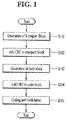
- FIG. 1 is a flowchart illustrating an exemplary encoding procedure.
- the encoding procedure as illustrated in FIG. 1 may be applied to numerous channel codes including a turbo code used in the LTE communication system.
- a turbo code used in the LTE communication system.
- the encoding procedure will be described based on terms according to the standard specifications of the LTE communication system.
- a transmitter may generate a transport block (TB) (step S101).
- the transmitter adds a cyclic redundancy check (CRC) bit for the TB to the TB (step S102).
- CRC cyclic redundancy check
- the transmitter may generate code blocks from the TB to which the CRC bits are added (step S103).
- the transmitter may segment the TB into the code blocks based on an input size of an encoder.
- the transmitter may add the CRC bits to each of the segmented code blocks (step S104).
- the size of the code block and the code block CRC bits may be 6144 bits.
- the transmitter may perform encoding and modulation with respect to each block which consists of a code block and code block CRC bits (step S105). For example, turbo coding may be applied as described previously.
- a decoding procedure may be performed in a reverse order of the encoding procedure of FIG. 1 .
- a receiver may decode each code block using a decoder corresponding to each encoder, configure one final TB, and perform CRC confirmation for the TB.
- the size of an input symbol may be different from the size of a TB from a media access control (MAC) layer. If the size of the TB is greater than a maximum size of the input symbol of the turbo code, the TB may be segmented into a plurality of code blocks (CBs). According to standard of the LTE communication system, the size of the CB may be equal to a value obtained by subtracting the CRC bits from 6144 bits.
- the input symbol of the turbo code may be defined as data including a CB and a CRC or data including a TB (e.g., the size of the TB is less than 6144 bits) and a CRC.
- the CRC bits are significantly less than 6144 bits (e.g., the CRC bits are a maximum of 24 bits). Therefore, in the following description, a CB may refer to a CB itself or a CB and corresponding CRC bits and a TB may refer to a TB itself or a TB and corresponding CRC bits, unless defined otherwise).
- FIG. 2 is a diagram illustrating an exemplary TB encoding procedure.
- FIG. 2 illustrates an encoding procedure of a TB 201 corresponding to the above-described encoding procedure in relation to FIG. 1 .
- a TB CRC 202 is added to the TB 201.
- the TB CRC 202 may be used to confirm the TB 201 during a decoding procedure.
- the TB 201 and the TB CRC 202 are divided into three CBs 203.
- the TB 201 may be divided into a plurality of CBs based on the input size of an encoder 205.
- CB CRCs 204 are added to the respective CBs 203.
- the CB CRCs 204 may be used to confirm the CBs 203 by the receiver.
- the CBs 203 and the CB CRCs 204 may be encoded through respective encoders 205 and respective modulators 205.
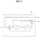
- FIG. 3 is a diagram illustrating an exemplary recursive systematic convolutional (RSC) encoder.
- An RSC encoder 300 of FIG. 3 may be used for turbo coding.
- m denotes input data
- C1 denotes a systematic bit stream
- C2 denotes a coded bit stream.
- the RSC encoder 300 has a code rate of 1/2.
- the RSC encoder 300 may be configured by feeding back an encoded output to an input of a non-recursive, non-systematic convolutional encoder.
- the encoder 300 includes two delayers 301 and 302. A value D of each of the delayers 301 and 302 may be determined according to a coding scheme.
- the delayers 301 and 302 may be configured by memories or shift registers.
- FIG. 4 is a diagram illustrating an LTE turbo encoder.
- a coding scheme of an LTE turbo encoder 400 uses a parallel concatenated convolutional code (PCCC) implemented through two 8-state constituent encoders 410 and 420 and one turbo code internal interleaver 430.
- PCCC parallel concatenated convolutional code
- the turbo encoder 400 includes the first constituent encoder 410, the second constituent encoder 420, and the turbo code internal interleaver 430.
- the first constituent encoder 410 and the second constituent encoder 420 are 8-state constituent encoders.
- Each of the first constituent encoder 410 and the second constituent encoder 420 has a structure similar to the RSC encoder of FIG. 3 .
- the first constituent encoder 410 and the second constituent encoder 420 include three delayers 411, 412, and 413 and three delayers 421, 422, 423, respectively.
- D denotes a value determined based on a coding scheme.
- c k denotes an input to the turbo encoder 400.
- Outputs from the first constituent encoder 410 and the second constituent encoder 420 are denoted as z k and z' k , respectively.
- An output from the turbo code internal interleaver 430 is denoted as c' k .
- each of the delayers 411, 412,4 13, 421, 422, and 423 may delay an input value by one clock.
- each of the delayers 411, 412, 413, 421, 422, and 423 may be configured to delay the input value by more than one clock according to internal configuration.
- Each of the delayers 411, 412, 413, 421, 422, and 423 may be comprised of a shift register and may be configured so as to delay an input bit by a preset clock and then output the input bit therethrough.
- the turbo code internal interleaver 430 may reduce an effect of a burst error which may be generated during signal transmission on a radio channel.
- the turbo code internal interleaver 430 may be a quadratic polynomial permutation (QPP) interleaver.
- QPP quadratic polynomial permutation
- a turbo code is a high-performance forward error correction (FEC) code used in the LTE communication system.
- a data block coded by the turbo code may include three subblocks.
- One subblock may correspond to m-bit payload data.
- Another subblock may include n/2 parity bits for a payload, calculated using an RSC code.
- the other subblock may include n/2 parity bits for permutation of payload data, calculated using the RSC code.
- the above permutation may be performed by the interleaver.
- the two different subblocks of parity bits may constitute one block together with the subblock for the payload.
- m is equal to n/2
- one block has a code rate of 1/3.
- a procedure in which the input c k reaches the encoded bit z k may be divided into two paths.
- the two paths include a first path connected to an output stage from an input stage without feedback and a second path fed back from the input stage back to the input stage.
- the input c k , the input c k passing through the delayer 411, and the input c k passing through the delayers 411, 412, and 413 are supplied to the output stage.
- a relationship between the input stage and the output stage for the first path may be expressed as a polynomial.
- the polynomial for the first path is referred to as a forward generator polynomial and may be expressed as g1 of the following equation indicated below.
- g 1 D 1 + D + D + D 3
- a polynomial for the second path is referred to as a recursive generator polynomial and may be expressed as g0 of the following equation indicated below.
- g 0 D 1 + D 2 + D 3
- Equations 1 and 2 "+” denotes exclusive OR (XOR) and 1 represents that an input is subjected to delay zero times.
- D n represents that an input is subjected to delay n times.
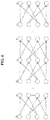
- FIG. 5 is a diagram illustrating an exemplary trellis according to an RSC encoder.
- FIG. 5 illustrates the structure of the trellis of the RSC encoder of FIG. 3 .
- S i denotes a state of i-th input data.
- each circle denotes a node.
- a line between nodes denotes a branch,
- a branch of a real line means a branch for an input value 1 and a branch of a dotted line means a branch for an input value 0.
- a value on the branch is expressed as m/C1C2 (input value/systematic bit, encoded bit).
- the trellis may have states exponentially proportional to the number of memories of the encoder. For example, if the encoder includes a memories, 2 a states may be included in the trellis.
- the trellis is a state machine illustrating state transition of an encoder allowable two states.
- a convolutional encoder such as the RSC encoder may perform encoding according to a trellis diagram.
- a codeword encoded by the RSC encoder may be decoded according to an algorithm based on a trellis structure. For example, a Viterbi or Bahl, Cocke, Jelinek and Raviv (BCJR) algorithm may be used.
- FIG. 6 is a diagram illustrating an exemplary trellis structure.
- n denotes the length of a codeword.
- additional bits are added to the end of an input sequence, thereby terminating a trellis.
- a sequence consisting of 0s is referred to as tail bits.
- the tail bits terminate the trellis by causing nodes of one state of the trellis to have a value of 0.
- the length of the codeword may be determined in consideration of the length k of input data and the length t of tail bits.
- the length n of the codeword may have a value of (k+t)/R.
- the length t of the tail bits may be determined as a length with which all delays (e.g., memories) of an encoder can be reset.
- the RSC encoder of FIG. 3 may use a total of two tail bits.
- the turbo encoder of LTE communication as illustrated in FIG. 4 may use three tail bits.
- the tail bits have a relatively short length as compared with the length of input data. As described above, since the length of the codeword is associated with the length of the tail bits, if the length of the codeword is limited, code rate loss may occur due to the tail bits. However, although code rate loss is generated due to the tail bits, trellis termination using the tail bits is widely used because of low complexity of calculation and excellent error correction performance.
- Puncturing is a scheme of puncturing a part of codewords. Through puncturing, since a part of codewords is punctured, partial codewords are not transmitted. For example, puncturing may be used to reduce code rate loss caused by addition of the tail bits.
- a receiver may perform decoding using a trellis corresponding to the sum of the length k of the input data and the length t of the tail bits. That is, the receiver may perform decoding under the assumption that the receiver has received codewords which are not punctured. In this case, the receiver may regard a branch from a node corresponding to a punctured bit (i.e., a bit which is not transmitted by a transmitter) as having no input value. That is, it is assumed that the input data for branches of a corresponding node is 0 or 1 with the same possibility.
- a CRC for a CB is added to the CB.
- the CRC may be determined as a remainder derived after data to be transmitted is divided by a preset check value used as a divisor. Generally, the CRC may be added to the end of the transmission data.
- the receiver may compare the remainder after reception data is divided by the preset check value with the CRC or determine whether a remainder after entire reception data including the CRC is divided by the check value is 0.
- the size of the CRC may be a maximum of 24 bits. Accordingly, the other bits except for the CRC bits may be determined as the size of the CB.
- the receiver may perform decoding with respect to each CB. Thereafter, the receiver may configure the TB from CBs and determine whether decoding has been successfully performed by checking the CRC for the TB.
- a CB CRC is used for early decoding termination. For example, if a CRC for one CB fails, the receiver may not decode the other CBs and transmit a negative acknowledgement (NACK) to the transmitter.
- NACK negative acknowledgement
- the transmitter may retransmit at least a part of transmission data. For example, the transmitter may retransmit a TB or one or more CBs. As an example, when the transmitter retransmits all of the TB, radio resources for retransmission may be excessively consumed.
- the receiver may transmit information about a CB (e.g., an index of a CB) in which CRC failure has occurred to the transmitter.
- the transmitter may increase the efficiency of radio resources by transmitting only the CB in which CRC failure has occurred using the information about the CB. However, if the number of CBs increases, the amount of data for feeding back the information about the CBs (e.g., indexes of the CBs) increases.
- the receiver may inform the transmitter through an ACK/NACK signal whether data has been successfully received.
- ACK/NACK for data received in an i-th subframe is transmitted in an (i+4)-th subframe. If NACK is received in the (i+4)-th subframe, retransmission may be performed in an (i+8)-th subframe. This is to consider a time for processing the TB and a time for generating ACK/NACK because channel code processing for processing the TB consumes much time.
- ACK/NACK and retransmission subframes may be determined based on a time for processing the TB, a time for generating ACK/NACK, and uplink subframe allocation (e.g., TDD uplink/downlink configuration).
- uplink subframe allocation e.g., TDD uplink/downlink configuration.
- ACK/NACK bundling and multiplexing may be used.
- the turbo code shows restricted improvement in an error rate if an SNR exceeds a predetermined value.
- a low-density parity-check (LDPC) code has been proposed.
- the LDPC code is a linear block code and is used in IEEE 802.11n and 802.11ac and digital video broadcasting (DVB).
- the LDPC code may include a generation matrix and a parity check matrix.
- data may be encoded through a multiplication operation of message bits and the generation matrix.
- the parity check matrix may be used instead of the generation matrix. For example, data may be encoded using the parity check matrix.
- the linear block code may be generated based on a generation matrix G or a parity check matrix H.
- the linear block code is configured such that the product Hc t of a transpose matrix of a codeword c and the parity check matrix has a value of 0 with respect to the whole codeword c.
- Decoding of the LDPC code may be performed, as identical to other linear block codes, by checking whether the product of the parity check matrix H and the codeword c is '0'. For example, decoding of the LDPC code may be performed by checking whether the product (i.e., Hc t ) of a transpose matrix of the codeword c and the parity check matrix is 0.
- the LDPC code may perform iterative decoding based on probability.
- the parity check matrix has been defined in a non-systematic form and a small weight has been uniformly applied to rows and columns of the parity check matrix.
- a weight may mean the number of 1s included in a row or a column.
- the density of elements having values other than 0 in a parity check matrix H of the LDPC code is low. Accordingly, the LDPC code has performance approximating to limits of Shannon's theorem while decoding complexity is kept low. Due to high error correction performance and low decoding complexity of this LDPC code, the LDPC code is suitable for high-speed wireless communication.
- the parity check matrix H may be used to generate the LDPC code.
- the matrix H includes a large number of 0s and a small number of 1s.
- the size of the matrix H may be 10 5 bits or more. Many memories may be needed to express the H matrix.
- elements of the matrix H may be expressed as subblocks of a predetermined size as illustrated in FIG. 7 . In FIG. 7 , each of the elements of the matrix H represents one subblock.
- a subblock is indicated by one integer index, so that the size of memories for expressing the matrix H may be reduced.
- Each subblock may be, for example, a permutation matrix of a predetermined size.
- FIG. 8 is a diagram illustrating an exemplary model matrix.
- a model matrix used to encode/decode the LDPC code is as illustrated in FIG. 8 .
- the model matrix may mean a parity check matrix including at least one subblock described below.
- the subblock may be referred to as the number of shifts in the following description.
- the model matrix may be extended to the parity check matrix based on a method which will be described later. Therefore, encoding and decoding based on a specific model matrix means encoding and decoding based on a parity check matrix generated by extending the model matrix.
- index '-1' indicates a zero matrix of a preset size.
- Index '0' indicates an identity matrix of a preset size.
- a positive index except for '-1' and '0' indicates the number of shifts.
- a subblock expressed as index '1' may mean a matrix obtained by shifting an identity matrix once in a specific direction.
- FIG. 9 is a diagram referenced to explain matrix transformation according to the number of shifts.
- FIG. 9 illustrates the case in which the size of a subblock is 4 rows and 4 columns.
- the subblock is shifted from an identity matrix three times to the right.
- the subblock in a parity check matrix of a structured LDPC code, the subblock may be represented using an integer index of '3'.
- encoding of the LDPC code may be performed by generating a generation matrix G from a parity check matrix H and encoding information bits using the generation matrix.
- Gaussian reduction is performed with respect to the parity check matrix H to configure a matrix in the form of [P T : I]. If the number of the information bits is k and the size of encoded codewords is n, a matrix P is a matrix including k rows and n-k columns and a matrix I is an identity matrix having a size of k.
- the parity check matrix H has the form of [P T : I]
- the generation matrix G has a form of [I : P T ].
- the encoded information bits may be expressed as a matrix x of one row and k columns.
- a codeword c is xG having a form of [x : xP].
- x denotes an information part (or a systematic part)
- xP denotes a parity part.
- the information bits may be encoded directly from the matrix H without deriving the matrix G by designing the matrix H as a specific structure without using Gaussian reduction.
- the product of the matrix G and a transpose matrix of the matrix H has a value of 0.
- the codeword may be obtained by adding parity bits to the end of the information bits.
- FIG. 10 is a flowchart illustrating an exemplary LDPC code decoding method.
- encoded data includes noise in a process of passing through a radio channel. Accordingly, a codeword c is expressed as a codeword c' including noise in a receiver.
- the receiver performs demultiplexing and demodulation with respect to a received signal (step S1000) and initializes decoding parameters (step S1005).
- the receiver updates a check node and a variable node (steps S1010 and S1015) and performs syndrome check (step S1020). That is, a decoding procedure may be ended by checking whether c'H T is 0. If c'H T is 0, the first k bits from c' may be determined as the information bits x. If c'H T is not 0, the information bit x may be recovered by searching for c' satisfying the condition that c'H T is 0 based on a decoding scheme such as a sum-product algorithm.
- FIG. 11 is a diagram illustrating an exemplary bipartite graph.
- left nodes v 0 , v 1 , ..., v 11 represent variable nodes and right nodes c 1 , c 2 , ..., c 6 represent check nodes.
- a bipartite graph is illustrated focusing on the variable node v 0 and check node c 1 for convenience of description. Connection lines of the bipartite graph of FIG. 11 may be referred to as edges.
- the bipartite graph of FIG. 11 may be generated from Hc t . Therefore, in FIG. 11 , edges from the variable node v 0 correspond to the first column of the parity check matrix H and edges from the check node c 1 correspond to the first row of the matrix H.
- the product of the parity check matrix H and a transpose matrix of the codeword matrix c should have a value of '0'. Accordingly, values of variable nodes connected to one check node should be 0. Consequently, in FIG. 11 , values of exclusive OR (XOR) of the variable nodes v 0 , v 1 , v 4 , v 6 , v 9 , v 11 connected to the check node c1 should be '0'.
- Syndrome check means checking as to whether a value of XOR of variable nodes connected to each check node is 0.
- the LDPC code may be used in an enhanced mobile broadband (eMBB) communication environment.
- the LDPC code may be used for a data channel.
- an LDPC code decoding method code using syndrome check instead of CRC has been proposed.
- syndrome check is performed during repeated decoding, a memory in which a log likelihood ratio for variable nodes is stored needs to be read every time for syndrome check. Therefore, power consumption and latency caused by memory reading may increase.
- a sum-product algorithm is used as a standard decoding algorithm for a capacity-approaching code (e.g., a turbo code or an LDPC code).
- a belief propagation algorithm is used as a decoding method using the sum-product algorithm.
- operations for check nodes and variable nodes of the sum-product algorithm are sequentially processed for decoding of the LDPC code. Therefore, in the layered belief propagation algorithm, a probability value of the first variable node is transferred to check nodes connected to the first variable node and an additional information value calculated based on the probability value transferred to each check node is transferred to variable nodes connected to each check node. Update for the other variable nodes is sequentially performed based on the transferred additional information value. Thus, probability values for all variable nodes may be updated.
- a probability value of an already updated variable node may be used for update of a specific variable node.
- decoding using the layered belief propagation algorithm is disadvantageous in that a decoding time increases relative to a flooding belief propagation algorithm by the length of a codeword. For example, the decoding time may increase by N times the length of the codeword.
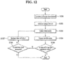
- FIG. 12 is a flowchart of an exemplary LDPC code decoding method using syndrome check.
- a receiver calculates a log likelihood ratio (LLR) value from a channel (S1201). For example, the receiver may calculate an LLR value of a received input signal or a codeword. Although not illustrated in FIG. 12 , the receiver may initialize variable nodes using the LLR value. In addition, the receiver initializes a value of a parameter Itr to 0 (S1202). The parameter Itr is a parameter indicating the number of repetitions.
- the receiver updates respective check nodes based on values of the variable nodes (S1203). For example, the respective check nodes may be updated based on the values of the variable nodes associated with the respective check nodes by a parity check matrix.
- the receiver may update the variable nodes (S1204). For example, the receiver may update the respective variable nodes based on values of the check nodes (e.g., LLR values of the check nodes) associated with the variable nodes by the parity check matrix.
- the receiver determines whether the value of the parameter Itr is less than a preset maximum value (S1205). If the value of the parameter Itr is less than the maximum value, the receiver may determine whether syndrome check is successful (S1206). For example, the receiver may perform syndrome check for the check nodes using the parity check matrix. For example, syndrome check may be performed according to the method described with reference to FIGS. 9 to 11 . If syndrome check is successful, decoding may be regarded as successful. Then, decoding may be ended. However, if syndrome check fails, the receiver may increase the value of the parameter Itr by 1 and repeat steps S1203 to S1205. However, when the number of repetitions reaches the preset maximum value, the receiver may regard decoding as failed. For example, if decoding fails, the receiver may end decoding and transmit negative acknowledgement (NACK) and/or a retransmission request to a transmitter.
- NACK negative acknowledgement
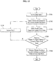
- FIG. 13 is a flowchart illustrating a syndrome check method according to an example.
- the syndrome check method illustrated in FIG. 13 may correspond to step S1206 of FIG. 12 .
- the receiver may set a parameter N to an initial value, 1 (S1301). Then, the receiver may update check nodes connected to an N th column of a parity check matrix (S1302). That is, the receiver may update the values of check nodes corresponding to elements having a value of 1 in the N th column of the parity check matrix. Further, the receiver may update variable nodes connected to the updated check nodes (S1303).
- the receiver may determine whether the value of N is equal to the number of columns of the parity check matrix (S1304). If the value of N is less than the number of columns of the parity check matrix, the receiver may increase the value of N by 1 (S1305) and repeat steps S1302 to S1304. Accordingly, check nodes and variable nodes corresponding to all columns of the parity check matrix may be sequentially updated.
- the receiver may determine whether decoding is successful by performing syndrome check on the parity check matrix (S1306). For example, the receiver may perform syndrome check by using a hard-decision LLR values for the check nodes.
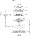
- FIG. 14 is a flowchart illustrating a syndrome check method according to an embodiment.
- the syndrome check method of FIG. 14 may correspond to step S1206 of FIG. 12 .
- the receiver may set the parameter N to an initial value, 1 (S1401).
- the receiver may then update the check nodes connected to the N th column of the parity check matrix (S1402). That is, the receiver may update the values of check nodes corresponding to elements having a value of 1 in the N th column of the parity check matrix.
- the receiver may update variable nodes connected to the updated check nodes (S1403).
- the receiver determines whether the syndrome check for the parity check matrix is successful (S1404) in the present embodiment.
- the syndrome check is performed before the check nodes and variable nodes for the entire parity check matrix are updated. Therefore, even before the check nodes and variable nodes for all columns of the parity check matrix are updated, the receiver may determine that the decoding is successful and terminate the decoding, if the syndrome check is successful. Therefore, time and power consumption for decoding may be reduced.
- the receiver may determine whether the value of N is equal to the number of columns of the parity check matrix (S1405). If the value of N is less than the number of columns of the parity check matrix, the receiver may increase the value of N by 1 (S1406) and repeat steps S1402 to S1405. Accordingly, check nodes and variable nodes corresponding to all columns of the parity check matrix may be sequentially updated.
- the receiver may determine whether the decoding is successful by performing syndrome check on the parity check matrix (S1407). For example, the receiver may perform syndrome check by using hard-decision LLR values for the check nodes.
- step S1407 may be omitted. This is because the syndrome check has already been performed in step S1404. In this case, it may be determined whether the decoding is successful in step S1404.
- FIGS. 15a and 15b are diagrams illustrating a syndrome check method according to an embodiment.
- FIGS. 15a and 15b are bipartite graphs according to an embodiment.
- the left nodes represent variable nodes v 1 , v 2 , v 3 , v 4 , and v 5
- the right nodes represent check nodes c 1 , c 2 , c 3 , and c 4 .
- the numbers in the variable nodes v 1 , v 2 , v 3 , v 4 , and v 5 represent the current values of the variable nodes.
- syndrome check may be performed on the check nodes c 1 , c 2 , c 3 , and c 4 by XOR-operating the values of the variable nodes v 1 , v 2 , v 3 , v 4 , and v 5 connected to the check nodes c 1 , c 2 , c 3 , and c 4 .
- "+" may represent an XOR operation.
- each variable node and each check node are sequentially updated, as described above with reference to FIGS. 13 and 14 .
- decoding may be performed again because of failure in syndrome check during the previous decoding.
- the data may be sequentially updated from the variable node v 1 .
- FIG. 15a is a bipartite graph before the variable node v 1 is updated.
- the values of the variable nodes v 1 , v 2 and v 3 are XOR-operated at the check node c 1 .
- the value of the check node c 1 is 1.
- FIG. 15b is a bipartite graph in which the first variable node v 1 and the check node c 1 connected to the first variable node v 1 are updated. Along with the sequential update of the variable nodes, the value of the variable node v 1 is updated to 0 in FIG. 15b . In addition, check nodes connected to the updated variable node are updated. In FIG. 15b , the variable node v 1 is connected only to the check node c 1 . Thus, only the value of the check node c 1 is updated. As illustrated in FIG. 15b , after the update, all of the check nodes c 1 , c 2 , c 3 , and c 4 have a value of 0.
- the receiver may know syndrome values for the remaining check nodes other than the updated check node. Accordingly, the receiver may confirm that the syndrome value of every check node is 0, and may terminate the decoding.
- a flag bit for each check node may be set.
- a flag may be set for a check node with a non-zero syndrome value (i.e., a check that has failed in syndrome check) in the previous decoding step. Further, when the syndrome value of the check node becomes 0 according to the update of the variable node, the corresponding flag may be released. Accordingly, the receiver may perform syndrome check without checking syndrome values for all the check nodes by checking only the syndrome value for the check node for which the flag is set.
- the conventional syndrome check method described above with reference to FIG. 13 continuously updates the remaining variable nodes and check nodes. Therefore, the conventional syndrome check method increases time and power consumption for decoding, since the receiver performs syndrome check after all the variable nodes and the check nodes are updated.
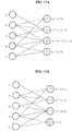
- FIGS. 16a and 16b are diagrams illustrating a hierarchical LDPC decoding method according to an embodiment.
- FIGS. 16a and 16b are bipartite graphs according to an embodiment.
- the left nodes are variable nodes v 1 , v 2 , v 3 , v 4 , and v 5
- the right nodes are check nodes c 1 , c 2 , c 3 , and c 4 .
- syndrome check may be performed for the check nodes c 1 , c 2 , c 3 , and c 4 by XOR-operating the values of the variable nodes v 1 , v 2 , v 3 , v 4 , and v 5 connected to the check nodes c 1 , c 2 , c 3 , and c 4 .
- "+" may represent an XOR operation in FIGS. 16a and 16b .
- a memory corresponding to all variable nodes connected to the check node needs to be read.
- the variable node v 4 is updated, the connected check nodes c 2 , c 3 , and c 4 are updated.
- the memory corresponding to the variable nodes v 2 , v 3 , v 4 , and v 5 needs to be read.
- relational expressions for determining syndrome values different from those in FIG. 16a may be used.
- a relational expression for determining a syndrome value of a check node may be modified not to include a variable node connected to a check node before the check node.
- the syndrome value of c 2 ' is determined by XOR-operating the values of variable nodes that do not overlap with the check node c 1 .
- a set of variable nodes connected to the previous check node may be referred to as a first set.
- a set of variable nodes connected to the check node subsequent to the previous check node may be referred to as a second set.
- the syndrome value of the modified subsequent check node may be determined by variable nodes included in the difference of the first set from the second set.
- the check node c 1 since the check node c 1 is the first node, it has the same relational expression as that in FIG. 16a . However, the check node c 2 ' has a relational expression in which the variable node v 2 is removed from that in FIG. 16a .
- variable node v 4 is updated.
- the check nodes c 2 ', c 3 ', and c 4 ' connected to the variable node v 4 are updated.
- the variable nodes connected to the check nodes c 2 ', c 3 ', and c 4 ' are v 4 , v 5 , v 2 , and v 3 , respectively.
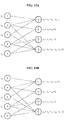
- FIGS. 17a and 17b are diagrams illustrating a hierarchical LDPC decoding method according to another embodiment.
- FIGS. 17a and 17b are bipartite graphs according to an embodiment.
- the left nodes are variable nodes v 1 , v 2 , v 3 , v 4 , and v 5
- the right nodes are check nodes c 1 , c 2 , c 3 , and c 4 .
- syndrome check may be performed for the check nodes c 1 , c 2 , c 3 , and c 4 by XOR-operating the values of the variable nodes v 1 , v 2 , v 3 , v 4 , and v 5 connected to the check nodes c 1 , c 2 , c 3 , and c 4 .
- "+" may represent an XOR operation in FIGS. 17a and 17b .
- FIG. 17a the order of check nodes illustrated in FIG. 16a is changed. This is done to minimize the number of variable nodes for calculating the syndrome values of the check nodes.
- the method of modifying relational expressions according to the invention as described above with reference to FIG. 16B may be applied to the check nodes of which the order has been changed in FIG. 17a . That is, the changed check nodes may remove variable nodes that overlap with their previously located check nodes from their relational expressions.
- FIG. 17b illustrates modified relational expressions according to the method described above in relation to FIG. 17a .
- the check node c 3 ' is not connected to any variable node. Therefore, the following effects may be obtained by reducing the number of variable nodes connected to the check nodes as illustrated in FIG. 17b .
- the value of each variable node connected to each syndrome check is read from the memory.
- the number of memory reads may be reduced by reducing the number of variable nodes connected to each check node. Considering that power consumption for memory reads in a decoder has a relatively high proportion, this may greatly reduce the power consumption of the memory.
- decoding time and delay may be reduced by reducing the number of memory reads.
- a pipeline may be used, for example, to reduce the decoding delay. When the pipeline is used, an updated value is used for decoding after the variable nodes connected to the check node are completely updated. In this case, the decoding time and delay may be further reduced.
- variable nodes v 1 , v 2 , and v 3 connected to the check node c 1 are read.
- updating one variable node requires reading the values of all the variable nodes associated with the check node connected to the corresponding variable node.
- variable nodes requiring reading according to the update of each variable node are listed in Table 1 below.
- variable nodes requiring reading according to the update of each variable node are listed in Table 2 below.
- Table 2 Updated variable node V1 V2 V3 V4 V5 Read variable node V1, V2, V3 V2, V4V1, V3V4, V5 V1, V2, V3V4, V5 V2, V4V2,V3,V4,V5 V2,V3,V4,V5
- the value of a variable node may be determined based on a likelihood ratio. Therefore, the above-described embodiments may be applied to a sum-product algorithm as well as a min-sum algorithm (e.g., a Viterbi algorithm).
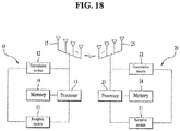
- FIG. 18 is a diagram schematically illustrating the configuration of devices to which embodiments of the present invention described in FIGS. 1 to 17b are applicable according to an embodiment of the present invention.
- a BS 10 may include a reception module 11, a transmission module 12, a processor 13, a memory 14, and a plurality of antennas 15.
- the transmission module 12 may transmit a variety of signals, data, and information to an external device (e.g., UE).
- the reception module 11 may receive a variety of signals, data, and information from the external device (e.g., UE).
- the reception module 11 and the transmission module 12 may be referred to as a transceiver.
- the processor 13 may control overall operation of the BS 10.
- the plural antennas 15 may be configured according to, for example, a 2-dimensional antenna arrangement.
- the processor 13 of the BS 10 may be configured to receive channel state information according to the examples proposed in the present invention.
- the processor 13 of the BS 10 processes information received by the BS 10 and information to be transmitted to the outside of the BS 10.
- the memory 14 may store the processed information for a predetermined time and may be replaced with a component such as a buffer (not shown).
- a UE 20 may include a reception module 21, a transmission module 22, a processor 23, a memory 24, and a plurality of antennas 25.
- Use of the plurality of antennas 25 means that the UE 20 supports Multiple Input Multiple Output (MIMO) transmission and reception using the plurality of antennas 25.
- the transmission module 22 may transmit a variety of signals, data, and information to an external device (e.g., BS).
- the reception module 21 may receive a variety of signals, data, and information from the external device (e.g., BS).
- the reception module 21 and the transmission module 22 may be referred to as a transceiver.
- the processor 23 may control overall operation of the BS 10.
- the processor 23 of the UE 10 may be configured to transmit channel state information according to the examples proposed in the present invention.
- the processor 23 of the UE 20 processes information received by the UE 20 and information to be transmitted to the outside of the UE 10.
- the memory 24 may store the processed information for a predetermined time and may be replaced with a component such as a buffer (not shown).
- the detailed configurations of the UE 10 may be implemented such that the above-described various embodiments of the present invention are independently applied or two or more embodiments of the present invention are simultaneously applied. Redundant matters will not be described herein for clarity.
- the BS has been mainly described as an example of a downlink transmission entity or an uplink reception entity and the UE has been mainly described as an example of a downlink reception entity or an uplink transmission entity
- the scope of the present invention is not limited thereto.
- a description of the BS may be identically applied when a cell, an antenna port, an antenna port group, a remote radio head (RRH), a transmission point, a reception point, an access point, or a relay is a downlink transmission entity to the UE or an uplink reception entity from the UE.
- RRH remote radio head
- the principle of the present invention described through various embodiments of the present invention may be identically applied to a relay acting as a downlink transmission entity to the UE or an uplink reception entity from the UE, or a relay acting as an uplink transmission entity to the BS or a downlink reception entity from the BS.
- the embodiments of the present invention may be implemented by various means, for example, hardware, firmware, software, or a combination thereof.
- the method according to the embodiments of the present invention may be implemented by one or more application specific integrated circuits (ASICs), digital signal processors (DSPs), digital signal processing devices (DSPDs), programmable logic devices (PLDs), field programmable gate arrays (FPGAs), processors, controllers, microcontrollers, or microprocessors.
- ASICs application specific integrated circuits
- DSPs digital signal processors
- DSPDs digital signal processing devices
- PLDs programmable logic devices
- FPGAs field programmable gate arrays
- processors controllers, microcontrollers, or microprocessors.
- the method according to the embodiments of the present invention may be implemented in the form of modules, procedures, functions, etc. performing the above-described functions or operations.
- Software code may be stored in a memory unit and executed by a processor.
- the memory unit may be located at the interior or exterior of the processor and may transmit and receive data to and from the processor via various known means.
- the embodiments of the present disclosure are applicable to various wireless access systems and broadcasting communication systems.
- the various wireless access systems include, for example, a 3GPP system, a 3GPP2 system and/or an IEEE 802.xx system.
- the embodiments of the present disclosure are applicable to all technical fields in which the various wireless access systems find their use as well as the various wireless access systems.
Landscapes
- Engineering & Computer Science (AREA)
- Physics & Mathematics (AREA)
- Probability & Statistics with Applications (AREA)
- Theoretical Computer Science (AREA)
- Computer Networks & Wireless Communication (AREA)
- Signal Processing (AREA)
- Mathematical Physics (AREA)
- Error Detection And Correction (AREA)
Claims (10)
- Verfahren zur geschichteten Dekodierung eines Low-Density-Parity-Check, LDPC-, Codes an einem Benutzergerät, UE, (20), wobei das Verfahren umfasst:Berechnen eines log Wahrscheinlichkeitverhältniswerts aus einem Eingangssignal;Initialisieren einer Vielzahl von variablen Knoten basierend auf dem Wahrscheinlichkeitsverhältniswert; unditeratives Aktualisieren einer Vielzahl von Prüfknoten auf der Grundlage sowohl einer Paritätsprüfungsmatrix als auch von Werten der Vielzahl von variablen Knoten, und Aktualisieren der Vielzahl von variablen Knoten auf der Grundlage sowohl der Paritätsprüfungsmatrix als auch von Werten der Vielzahl von Prüfknoten, bis bestimmt wird, ob die Dekodierung des Eingangssignals erfolgreich oder fehlgeschlagen ist auf der Grundlage einer Syndromprüfung für die Vielzahl von Prüfknoten,wobei die Iteration umfasst:sequentielles Aktualisieren der Vielzahl von variablen Knoten, wobei jedes Mal ein variabler Knoten aktualisiert wird; undDurchführen einer Syndromprüfung für die Vielzahl von Prüfknoten,wobei die Verknüpfung zwischen der Vielzahl von Prüfknoten und der Vielzahl von variablen Knoten auf der Grundlage der Paritätsprüfungsmatrix bestimmt wird,wobei, falls die Syndromprüfwerte aller der Vielzahl von Prüfknoten 0 sind, bestimmt wird, dass die Dekodierung erfolgreich ist, unddadurch gekennzeichnet, dassein Syndromprüfwert eines ersten Prüfknotens in der Vielzahl von Prüfknoten auf der Grundlage von Restvariablenknoten unter den mit dem ersten Prüfknoten verbundenen Variablenknoten bestimmt wird, undwobei die verbleibenden variablen Knoten für den ersten Prüfknoten bestimmt werden durch Ausschließen von variablen Knoten, die mit einem Prüfknoten vor dem ersten Prüfknoten, unter den variablen Knoten, überlappen, die mit dem ersten Prüfknoten verbunden sind.
- Verfahren nach Anspruch 1, wobei, wenn die Iteration eine vorbestimmte Anzahl von Malen oder mehr wiederholt wird, festgestellt wird, dass die Dekodierung fehlgeschlagen ist.
- Verfahren nach Anspruch 1, wobei das Durchführen der Syndromprüfung das Durchführen der Syndromprüfung unter Verwendung von Syndromprüfwerten von Prüfknoten, die mit einem bei einer derzeitigen Iteration aktualisierten Variablenknoten verbunden sind, und von Syndromprüfwerten von verbleibenden Prüfknoten, die bei einer vorherigen Iteration berechnet wurden, umfasst.
- Verfahren nach Anspruch 3, wobei für jeden der Vielzahl von Prüfknoten ein 1-Bit-Flag gesetzt wird, das einen Syndromprüfwert anzeigt.
- Verfahren nach Anspruch 1, wobei die Durchführung der Syndromprüfung auf einer Exklusiv-ODER, XOR,-Operation basiert.
- Ein Benutzergerät, UE, (20), umfassend:einen Transceiver (21, 22), der konfiguriert ist, ein Signal zu senden und zu empfangen;einen Speicher (24); undeinen Prozessor (23), der konfiguriert ist, den Transceiver und den Speicher zu steuern,wobei der Prozessor (23) weiter konfiguriert ist, um:einen log Wahrscheinlichkeitsverhältniswert aus einem Eingangssignal zu berechnen,eine Vielzahl von variablen Knoten basierend auf dem Wahrscheinlichkeitsverhältniswert zu initialisieren, undeine Vielzahl von Prüfknoten auf der Basis von sowohl einer Paritätsprüfungsmatrix als auch von Werten der Vielzahl von variablen Knoten iterativ zu aktualisieren, und die Vielzahl von variablen Knoten auf der Basis sowohl der Paritätsprüfungsmatrix als auch von Werten der Vielzahl von Prüfknoten zu aktualisieren, bis bestimmt wird, ob die Dekodierung des Eingangssignals erfolgreich oder fehlgeschlagen ist auf der Basis der Syndromprüfung für die Vielzahl von Prüfknoten, undwobei die Vielzahl von variablen Knoten sequentiell aktualisiert werden,wobei die Syndromprüfung für die Vielzahl von Prüfknoten jedes Mal durchgeführt wird, wenn ein variabler Knoten aktualisiert wird,wobei die Verknüpfung zwischen der Vielzahl von Prüfknoten und der Vielzahl von variablen Knoten auf der Grundlage der Paritätsprüfungsmatrix bestimmt wird,wobei, wenn die Syndromprüfwerte aller der Vielzahl von Prüfknoten 0 sind, bestimmt wird, dass die Dekodierung erfolgreich ist, unddadurch gekennzeichnet, dassein Syndromprüfwert eines ersten Prüfknotens in der Vielzahl von Prüfknoten auf der Grundlage von Restvariablenknoten unter den mit dem ersten Prüfknoten verbundenen variablen Knoten bestimmt wird, undwobei die verbleibenden variablen Knoten für den ersten Prüfknoten bestimmt werden durch Ausschließen variabler Knoten, die mit einem Prüfknoten vor dem ersten Prüfknoten überlappen, unter den variablen Knoten, die mit dem ersten Prüfknoten verbunden sind.
- UE nach Anspruch 6, wobei, wenn die Iteration der Aktualisierung der Vielzahl von variablen Knoten und der Syndromprüfung für die Vielzahl von Prüfknoten eine vorbestimmte Anzahl von Malen oder mehr wiederholt wird, bestimmt wird, dass die Dekodierung fehlgeschlagen ist.
- UE nach Anspruch 6, wobei der Prozessor (23) ferner konfiguriert ist, die Syndromprüfung unter Verwendung von Syndromprüfwerten von Prüfknoten, die mit einem bei einer derzeitigen Iteration aktualisierten Variablenknoten verbunden sind, und von Syndromprüfwerten von verbleibenden Prüfknoten, die bei einer vorherigen Iteration berechnet wurden, durchzuführen.
- UE nach Anspruch 8, wobei für jeden der Vielzahl von Prüfknoten ein 1-bit-Flag gesetzt ist, das einen Syndromprüfwert anzeigt.
- UE nach Anspruch 7, wobei die Syndromprüfung auf Basis einer Exklusiv-ODER, XOR,-Operation durchgeführt wird.
Applications Claiming Priority (1)
| Application Number | Priority Date | Filing Date | Title |
|---|---|---|---|
| PCT/KR2017/002546 WO2018164297A1 (ko) | 2017-03-09 | 2017-03-09 | Ldpc 코드의 계층적 복호화 방법 및 이를 위한 장치 |
Publications (3)
| Publication Number | Publication Date |
|---|---|
| EP3595203A1 EP3595203A1 (de) | 2020-01-15 |
| EP3595203A4 EP3595203A4 (de) | 2020-12-02 |
| EP3595203B1 true EP3595203B1 (de) | 2021-11-10 |
Family
ID=63447922
Family Applications (1)
| Application Number | Title | Priority Date | Filing Date |
|---|---|---|---|
| EP17899375.4A Active EP3595203B1 (de) | 2017-03-09 | 2017-03-09 | Verfahren zur geschichteten decodierung für ldpc-code und vorrichtung dafür |
Country Status (5)
| Country | Link |
|---|---|
| US (1) | US11206042B2 (de) |
| EP (1) | EP3595203B1 (de) |
| JP (1) | JP6821825B2 (de) |
| CN (1) | CN110383727B (de) |
| WO (1) | WO2018164297A1 (de) |
Families Citing this family (5)
| Publication number | Priority date | Publication date | Assignee | Title |
|---|---|---|---|---|
| KR102525414B1 (ko) * | 2020-07-29 | 2023-04-25 | 한국전자통신연구원 | LDPC(low-density parity-check) 부호의 복호화 방법 및 장치 |
| CN114415817B (zh) * | 2020-10-28 | 2024-05-07 | 北京小米移动软件有限公司 | 显示控制方法、电子设备及存储介质 |
| EP4329202A4 (de) | 2021-05-25 | 2024-10-16 | Samsung Electronics Co., Ltd. | Auf neuronalem netzwerk basierender selbstkorrigierender min-sum-decodierer und elektronische vorrichtung damit |
| US11817952B2 (en) * | 2022-01-31 | 2023-11-14 | Dialog Semiconductor (Uk) Limited | Systems and methods for providing end-to-end data protection |
| CN118484152B (zh) * | 2024-07-16 | 2024-09-24 | 济南浪潮数据技术有限公司 | 数据的调用方法及装置、存储介质及电子设备 |
Family Cites Families (19)
| Publication number | Priority date | Publication date | Assignee | Title |
|---|---|---|---|---|
| JP2005045735A (ja) | 2003-07-25 | 2005-02-17 | Sony Corp | 符号検出装置及び方法、復号装置及び方法、並びに情報処理装置及び方法 |
| KR101147768B1 (ko) | 2005-12-27 | 2012-05-25 | 엘지전자 주식회사 | 채널 코드를 이용한 복호화 방법 및 장치 |
| JP2009100222A (ja) | 2007-10-16 | 2009-05-07 | Toshiba Corp | 低密度パリティ検査符号の復号装置およびその方法 |
| JP5493602B2 (ja) * | 2009-08-31 | 2014-05-14 | 富士通株式会社 | 復号化装置及び復号化方法 |
| JP5790029B2 (ja) * | 2011-03-01 | 2015-10-07 | ソニー株式会社 | 復号装置、復号方法、およびプログラム |
| US8826096B2 (en) | 2011-12-29 | 2014-09-02 | Korea Advanced Institute Of Science And Technology | Method of decoding LDPC code for producing several different decoders using parity-check matrix of LDPC code and LDPC code system including the same |
| KR101968746B1 (ko) * | 2011-12-30 | 2019-04-15 | 삼성전자주식회사 | 저장 장치로부터 데이터를 읽는 읽기 방법, 에러 정정 장치, 그리고 에러 정정 코드 디코더를 포함하는 저장 시스템 |
| US9141467B2 (en) * | 2012-03-23 | 2015-09-22 | Samsung Electronics Co., Ltd. | Semiconductor memory system including Reed-Solomon low density parity check decoder and read method thereof |
| KR101926608B1 (ko) | 2012-08-27 | 2018-12-07 | 삼성전자 주식회사 | 경 판정 디코딩 방법 및 이를 이용한 저밀도 패리티 체크 디코더 |
| US9612903B2 (en) * | 2012-10-11 | 2017-04-04 | Micron Technology, Inc. | Updating reliability data with a variable node and check nodes |
| US9191256B2 (en) | 2012-12-03 | 2015-11-17 | Digital PowerRadio, LLC | Systems and methods for advanced iterative decoding and channel estimation of concatenated coding systems |
| US8984376B1 (en) | 2013-03-14 | 2015-03-17 | Pmc-Sierra Us, Inc. | System and method for avoiding error mechanisms in layered iterative decoding |
| US9136877B1 (en) * | 2013-03-15 | 2015-09-15 | Sandisk Enterprise Ip Llc | Syndrome layered decoding for LDPC codes |
| KR102189440B1 (ko) * | 2014-08-25 | 2020-12-14 | 삼성전자주식회사 | 에러 정정 디코더를 포함하는 스토리지 장치 및 에러 정정 디코더의 동작 방법 |
| KR102556479B1 (ko) * | 2015-03-20 | 2023-07-17 | 에스케이하이닉스 주식회사 | Ldpc 디코더, 반도체 메모리 시스템 및 그것의 동작 방법 |
| US9977713B2 (en) * | 2015-03-20 | 2018-05-22 | SK Hynix Inc. | LDPC decoder, semiconductor memory system and operating method thereof |
| US20170134048A1 (en) * | 2015-11-10 | 2017-05-11 | Samsung Electronics Co., Ltd. | Message-passing based decoding using syndrome information, and related methods |
| KR102706725B1 (ko) * | 2018-07-03 | 2024-09-19 | 에스케이하이닉스 주식회사 | 메모리 컨트롤러 및 이의 동작 방법 |
| CN114270710B (zh) * | 2019-09-10 | 2026-03-03 | 三星电子株式会社 | 通信或广播系统中的数据解码方法和装置 |
-
2017
- 2017-03-09 JP JP2019548987A patent/JP6821825B2/ja active Active
- 2017-03-09 CN CN201780088167.XA patent/CN110383727B/zh active Active
- 2017-03-09 WO PCT/KR2017/002546 patent/WO2018164297A1/ko not_active Ceased
- 2017-03-09 US US16/492,458 patent/US11206042B2/en active Active
- 2017-03-09 EP EP17899375.4A patent/EP3595203B1/de active Active
Also Published As
| Publication number | Publication date |
|---|---|
| CN110383727A (zh) | 2019-10-25 |
| US20210218418A1 (en) | 2021-07-15 |
| EP3595203A1 (de) | 2020-01-15 |
| JP6821825B2 (ja) | 2021-01-27 |
| WO2018164297A1 (ko) | 2018-09-13 |
| US11206042B2 (en) | 2021-12-21 |
| JP2020511079A (ja) | 2020-04-09 |
| CN110383727B (zh) | 2022-01-11 |
| EP3595203A4 (de) | 2020-12-02 |
Similar Documents
| Publication | Publication Date | Title |
|---|---|---|
| KR102131834B1 (ko) | Qc ldpc 코드의 레이트 매칭 방법 및 이를 위한 장치 | |
| US10903857B2 (en) | Data retransmission method for polar code, and device therefor | |
| US11777525B2 (en) | Method for transmitting LDPC code using row-orthogonal and apparatus therefor | |
| EP3567730A2 (de) | Verfahren zur auswahl eines ldpc-basiscodes bei einem multi-lpdc-code und vorrichtung dafür | |
| US10116332B2 (en) | Method for configuring circular buffer including outer code parity and apparatus therefor | |
| US20170279464A1 (en) | Method of ldpc code encoding for reducing signal overhead and apparatus therefor | |
| US10756761B2 (en) | Method for dividing carrying block of LDPC code and apparatus therefor | |
| US11271591B2 (en) | SC-LDPC code encoding method and device therefor | |
| EP3595203B1 (de) | Verfahren zur geschichteten decodierung für ldpc-code und vorrichtung dafür | |
| US10819372B2 (en) | Method for dividing transport block of LDPC code and apparatus therefor | |
| US11082060B2 (en) | LPDC code transmission method using row-orthogonal structure and apparatus therefor | |
| KR101835341B1 (ko) | Sc-ldpc 코드의 쌍방향 슬라이딩 윈도우 복호 방법 및 이를 위한 장치 |
Legal Events
| Date | Code | Title | Description |
|---|---|---|---|
| STAA | Information on the status of an ep patent application or granted ep patent |
Free format text: STATUS: THE INTERNATIONAL PUBLICATION HAS BEEN MADE |
|
| PUAI | Public reference made under article 153(3) epc to a published international application that has entered the european phase |
Free format text: ORIGINAL CODE: 0009012 |
|
| STAA | Information on the status of an ep patent application or granted ep patent |
Free format text: STATUS: REQUEST FOR EXAMINATION WAS MADE |
|
| 17P | Request for examination filed |
Effective date: 20190912 |
|
| AK | Designated contracting states |
Kind code of ref document: A1 Designated state(s): AL AT BE BG CH CY CZ DE DK EE ES FI FR GB GR HR HU IE IS IT LI LT LU LV MC MK MT NL NO PL PT RO RS SE SI SK SM TR |
|
| AX | Request for extension of the european patent |
Extension state: BA ME |
|
| DAV | Request for validation of the european patent (deleted) | ||
| DAX | Request for extension of the european patent (deleted) | ||
| A4 | Supplementary search report drawn up and despatched |
Effective date: 20201103 |
|
| RIC1 | Information provided on ipc code assigned before grant |
Ipc: H03M 13/11 20060101ALI20201028BHEP Ipc: H04L 1/00 20060101AFI20201028BHEP |
|
| RIC1 | Information provided on ipc code assigned before grant |
Ipc: H04L 1/00 20060101AFI20210506BHEP Ipc: H03M 13/11 20060101ALI20210506BHEP |
|
| GRAP | Despatch of communication of intention to grant a patent |
Free format text: ORIGINAL CODE: EPIDOSNIGR1 |
|
| STAA | Information on the status of an ep patent application or granted ep patent |
Free format text: STATUS: GRANT OF PATENT IS INTENDED |
|
| INTG | Intention to grant announced |
Effective date: 20210611 |
|
| GRAS | Grant fee paid |
Free format text: ORIGINAL CODE: EPIDOSNIGR3 |
|
| GRAA | (expected) grant |
Free format text: ORIGINAL CODE: 0009210 |
|
| STAA | Information on the status of an ep patent application or granted ep patent |
Free format text: STATUS: THE PATENT HAS BEEN GRANTED |
|
| AK | Designated contracting states |
Kind code of ref document: B1 Designated state(s): AL AT BE BG CH CY CZ DE DK EE ES FI FR GB GR HR HU IE IS IT LI LT LU LV MC MK MT NL NO PL PT RO RS SE SI SK SM TR |
|
| REG | Reference to a national code |
Ref country code: GB Ref legal event code: FG4D |
|
| REG | Reference to a national code |
Ref country code: AT Ref legal event code: REF Ref document number: 1447052 Country of ref document: AT Kind code of ref document: T Effective date: 20211115 Ref country code: CH Ref legal event code: EP |
|
| REG | Reference to a national code |
Ref country code: DE Ref legal event code: R096 Ref document number: 602017049289 Country of ref document: DE |
|
| REG | Reference to a national code |
Ref country code: IE Ref legal event code: FG4D |
|
| REG | Reference to a national code |
Ref country code: LT Ref legal event code: MG9D |
|
| REG | Reference to a national code |
Ref country code: NL Ref legal event code: MP Effective date: 20211110 |
|
| REG | Reference to a national code |
Ref country code: AT Ref legal event code: MK05 Ref document number: 1447052 Country of ref document: AT Kind code of ref document: T Effective date: 20211110 |
|
| PG25 | Lapsed in a contracting state [announced via postgrant information from national office to epo] |
Ref country code: RS Free format text: LAPSE BECAUSE OF FAILURE TO SUBMIT A TRANSLATION OF THE DESCRIPTION OR TO PAY THE FEE WITHIN THE PRESCRIBED TIME-LIMIT Effective date: 20211110 Ref country code: LT Free format text: LAPSE BECAUSE OF FAILURE TO SUBMIT A TRANSLATION OF THE DESCRIPTION OR TO PAY THE FEE WITHIN THE PRESCRIBED TIME-LIMIT Effective date: 20211110 Ref country code: FI Free format text: LAPSE BECAUSE OF FAILURE TO SUBMIT A TRANSLATION OF THE DESCRIPTION OR TO PAY THE FEE WITHIN THE PRESCRIBED TIME-LIMIT Effective date: 20211110 Ref country code: BG Free format text: LAPSE BECAUSE OF FAILURE TO SUBMIT A TRANSLATION OF THE DESCRIPTION OR TO PAY THE FEE WITHIN THE PRESCRIBED TIME-LIMIT Effective date: 20220210 Ref country code: AT Free format text: LAPSE BECAUSE OF FAILURE TO SUBMIT A TRANSLATION OF THE DESCRIPTION OR TO PAY THE FEE WITHIN THE PRESCRIBED TIME-LIMIT Effective date: 20211110 |
|
| PG25 | Lapsed in a contracting state [announced via postgrant information from national office to epo] |
Ref country code: IS Free format text: LAPSE BECAUSE OF FAILURE TO SUBMIT A TRANSLATION OF THE DESCRIPTION OR TO PAY THE FEE WITHIN THE PRESCRIBED TIME-LIMIT Effective date: 20220310 Ref country code: SE Free format text: LAPSE BECAUSE OF FAILURE TO SUBMIT A TRANSLATION OF THE DESCRIPTION OR TO PAY THE FEE WITHIN THE PRESCRIBED TIME-LIMIT Effective date: 20211110 Ref country code: PT Free format text: LAPSE BECAUSE OF FAILURE TO SUBMIT A TRANSLATION OF THE DESCRIPTION OR TO PAY THE FEE WITHIN THE PRESCRIBED TIME-LIMIT Effective date: 20220310 Ref country code: PL Free format text: LAPSE BECAUSE OF FAILURE TO SUBMIT A TRANSLATION OF THE DESCRIPTION OR TO PAY THE FEE WITHIN THE PRESCRIBED TIME-LIMIT Effective date: 20211110 Ref country code: NO Free format text: LAPSE BECAUSE OF FAILURE TO SUBMIT A TRANSLATION OF THE DESCRIPTION OR TO PAY THE FEE WITHIN THE PRESCRIBED TIME-LIMIT Effective date: 20220210 Ref country code: NL Free format text: LAPSE BECAUSE OF FAILURE TO SUBMIT A TRANSLATION OF THE DESCRIPTION OR TO PAY THE FEE WITHIN THE PRESCRIBED TIME-LIMIT Effective date: 20211110 Ref country code: LV Free format text: LAPSE BECAUSE OF FAILURE TO SUBMIT A TRANSLATION OF THE DESCRIPTION OR TO PAY THE FEE WITHIN THE PRESCRIBED TIME-LIMIT Effective date: 20211110 Ref country code: HR Free format text: LAPSE BECAUSE OF FAILURE TO SUBMIT A TRANSLATION OF THE DESCRIPTION OR TO PAY THE FEE WITHIN THE PRESCRIBED TIME-LIMIT Effective date: 20211110 Ref country code: GR Free format text: LAPSE BECAUSE OF FAILURE TO SUBMIT A TRANSLATION OF THE DESCRIPTION OR TO PAY THE FEE WITHIN THE PRESCRIBED TIME-LIMIT Effective date: 20220211 Ref country code: ES Free format text: LAPSE BECAUSE OF FAILURE TO SUBMIT A TRANSLATION OF THE DESCRIPTION OR TO PAY THE FEE WITHIN THE PRESCRIBED TIME-LIMIT Effective date: 20211110 |
|
| PG25 | Lapsed in a contracting state [announced via postgrant information from national office to epo] |
Ref country code: SM Free format text: LAPSE BECAUSE OF FAILURE TO SUBMIT A TRANSLATION OF THE DESCRIPTION OR TO PAY THE FEE WITHIN THE PRESCRIBED TIME-LIMIT Effective date: 20211110 Ref country code: SK Free format text: LAPSE BECAUSE OF FAILURE TO SUBMIT A TRANSLATION OF THE DESCRIPTION OR TO PAY THE FEE WITHIN THE PRESCRIBED TIME-LIMIT Effective date: 20211110 Ref country code: RO Free format text: LAPSE BECAUSE OF FAILURE TO SUBMIT A TRANSLATION OF THE DESCRIPTION OR TO PAY THE FEE WITHIN THE PRESCRIBED TIME-LIMIT Effective date: 20211110 Ref country code: EE Free format text: LAPSE BECAUSE OF FAILURE TO SUBMIT A TRANSLATION OF THE DESCRIPTION OR TO PAY THE FEE WITHIN THE PRESCRIBED TIME-LIMIT Effective date: 20211110 Ref country code: DK Free format text: LAPSE BECAUSE OF FAILURE TO SUBMIT A TRANSLATION OF THE DESCRIPTION OR TO PAY THE FEE WITHIN THE PRESCRIBED TIME-LIMIT Effective date: 20211110 Ref country code: CZ Free format text: LAPSE BECAUSE OF FAILURE TO SUBMIT A TRANSLATION OF THE DESCRIPTION OR TO PAY THE FEE WITHIN THE PRESCRIBED TIME-LIMIT Effective date: 20211110 |
|
| REG | Reference to a national code |
Ref country code: DE Ref legal event code: R097 Ref document number: 602017049289 Country of ref document: DE |
|
| PLBE | No opposition filed within time limit |
Free format text: ORIGINAL CODE: 0009261 |
|
| STAA | Information on the status of an ep patent application or granted ep patent |
Free format text: STATUS: NO OPPOSITION FILED WITHIN TIME LIMIT |
|
| 26N | No opposition filed |
Effective date: 20220811 |
|
| PG25 | Lapsed in a contracting state [announced via postgrant information from national office to epo] |
Ref country code: MC Free format text: LAPSE BECAUSE OF FAILURE TO SUBMIT A TRANSLATION OF THE DESCRIPTION OR TO PAY THE FEE WITHIN THE PRESCRIBED TIME-LIMIT Effective date: 20211110 Ref country code: AL Free format text: LAPSE BECAUSE OF FAILURE TO SUBMIT A TRANSLATION OF THE DESCRIPTION OR TO PAY THE FEE WITHIN THE PRESCRIBED TIME-LIMIT Effective date: 20211110 |
|
| REG | Reference to a national code |
Ref country code: CH Ref legal event code: PL |
|
| GBPC | Gb: european patent ceased through non-payment of renewal fee |
Effective date: 20220309 |
|
| PG25 | Lapsed in a contracting state [announced via postgrant information from national office to epo] |
Ref country code: SI Free format text: LAPSE BECAUSE OF FAILURE TO SUBMIT A TRANSLATION OF THE DESCRIPTION OR TO PAY THE FEE WITHIN THE PRESCRIBED TIME-LIMIT Effective date: 20211110 |
|
| REG | Reference to a national code |
Ref country code: BE Ref legal event code: MM Effective date: 20220331 |
|
| PG25 | Lapsed in a contracting state [announced via postgrant information from national office to epo] |
Ref country code: LU Free format text: LAPSE BECAUSE OF NON-PAYMENT OF DUE FEES Effective date: 20220309 Ref country code: LI Free format text: LAPSE BECAUSE OF NON-PAYMENT OF DUE FEES Effective date: 20220331 Ref country code: IE Free format text: LAPSE BECAUSE OF NON-PAYMENT OF DUE FEES Effective date: 20220309 Ref country code: GB Free format text: LAPSE BECAUSE OF NON-PAYMENT OF DUE FEES Effective date: 20220309 Ref country code: FR Free format text: LAPSE BECAUSE OF NON-PAYMENT OF DUE FEES Effective date: 20220331 Ref country code: CH Free format text: LAPSE BECAUSE OF NON-PAYMENT OF DUE FEES Effective date: 20220331 |
|
| PG25 | Lapsed in a contracting state [announced via postgrant information from national office to epo] |
Ref country code: BE Free format text: LAPSE BECAUSE OF NON-PAYMENT OF DUE FEES Effective date: 20220331 |
|
| PG25 | Lapsed in a contracting state [announced via postgrant information from national office to epo] |
Ref country code: IT Free format text: LAPSE BECAUSE OF FAILURE TO SUBMIT A TRANSLATION OF THE DESCRIPTION OR TO PAY THE FEE WITHIN THE PRESCRIBED TIME-LIMIT Effective date: 20211110 |
|
| PG25 | Lapsed in a contracting state [announced via postgrant information from national office to epo] |
Ref country code: MK Free format text: LAPSE BECAUSE OF FAILURE TO SUBMIT A TRANSLATION OF THE DESCRIPTION OR TO PAY THE FEE WITHIN THE PRESCRIBED TIME-LIMIT Effective date: 20211110 Ref country code: CY Free format text: LAPSE BECAUSE OF FAILURE TO SUBMIT A TRANSLATION OF THE DESCRIPTION OR TO PAY THE FEE WITHIN THE PRESCRIBED TIME-LIMIT Effective date: 20211110 |
|
| PG25 | Lapsed in a contracting state [announced via postgrant information from national office to epo] |
Ref country code: HU Free format text: LAPSE BECAUSE OF FAILURE TO SUBMIT A TRANSLATION OF THE DESCRIPTION OR TO PAY THE FEE WITHIN THE PRESCRIBED TIME-LIMIT; INVALID AB INITIO Effective date: 20170309 |
|
| PG25 | Lapsed in a contracting state [announced via postgrant information from national office to epo] |
Ref country code: TR Free format text: LAPSE BECAUSE OF FAILURE TO SUBMIT A TRANSLATION OF THE DESCRIPTION OR TO PAY THE FEE WITHIN THE PRESCRIBED TIME-LIMIT Effective date: 20211110 |
|
| PG25 | Lapsed in a contracting state [announced via postgrant information from national office to epo] |
Ref country code: MT Free format text: LAPSE BECAUSE OF FAILURE TO SUBMIT A TRANSLATION OF THE DESCRIPTION OR TO PAY THE FEE WITHIN THE PRESCRIBED TIME-LIMIT Effective date: 20211110 |
|
| PGFP | Annual fee paid to national office [announced via postgrant information from national office to epo] |
Ref country code: DE Payment date: 20250205 Year of fee payment: 9 |