EP3594633B1 - Laserstrahlbestrahlungsdetektionsvorrichtung, laserstrahlbestrahlungsdetektionsverfahren und laserstrahlbestrahlungsdetektionssystem - Google Patents
Laserstrahlbestrahlungsdetektionsvorrichtung, laserstrahlbestrahlungsdetektionsverfahren und laserstrahlbestrahlungsdetektionssystem Download PDFInfo
- Publication number
- EP3594633B1 EP3594633B1 EP17899963.7A EP17899963A EP3594633B1 EP 3594633 B1 EP3594633 B1 EP 3594633B1 EP 17899963 A EP17899963 A EP 17899963A EP 3594633 B1 EP3594633 B1 EP 3594633B1
- Authority
- EP
- European Patent Office
- Prior art keywords
- laser beam
- end portion
- trajectory
- light ray
- emission position
- Prior art date
- Legal status (The legal status is an assumption and is not a legal conclusion. Google has not performed a legal analysis and makes no representation as to the accuracy of the status listed.)
- Active
Links
Images






Classifications
-
- H—ELECTRICITY
- H01—ELECTRIC ELEMENTS
- H01S—DEVICES USING THE PROCESS OF LIGHT AMPLIFICATION BY STIMULATED EMISSION OF RADIATION [LASER] TO AMPLIFY OR GENERATE LIGHT; DEVICES USING STIMULATED EMISSION OF ELECTROMAGNETIC RADIATION IN WAVE RANGES OTHER THAN OPTICAL
- H01S3/00—Lasers, i.e. devices using stimulated emission of electromagnetic radiation in the infrared, visible or ultraviolet wave range
- H01S3/10—Controlling the intensity, frequency, phase, polarisation or direction of the emitted radiation, e.g. switching, gating, modulating or demodulating
- H01S3/10007—Controlling the intensity, frequency, phase, polarisation or direction of the emitted radiation, e.g. switching, gating, modulating or demodulating in optical amplifiers
- H01S3/10023—Controlling the intensity, frequency, phase, polarisation or direction of the emitted radiation, e.g. switching, gating, modulating or demodulating in optical amplifiers by functional association of additional optical elements, e.g. filters, gratings, reflectors
-
- B—PERFORMING OPERATIONS; TRANSPORTING
- B64—AIRCRAFT; AVIATION; COSMONAUTICS
- B64D—EQUIPMENT FOR FITTING IN OR TO AIRCRAFT; FLIGHT SUITS; PARACHUTES; ARRANGEMENT OR MOUNTING OF POWER PLANTS OR PROPULSION TRANSMISSIONS IN AIRCRAFT
- B64D45/00—Aircraft indicators or protectors not otherwise provided for
- B64D45/0015—Devices specially adapted for the protection against criminal attack, e.g. anti-hijacking systems
-
- B—PERFORMING OPERATIONS; TRANSPORTING
- B64—AIRCRAFT; AVIATION; COSMONAUTICS
- B64D—EQUIPMENT FOR FITTING IN OR TO AIRCRAFT; FLIGHT SUITS; PARACHUTES; ARRANGEMENT OR MOUNTING OF POWER PLANTS OR PROPULSION TRANSMISSIONS IN AIRCRAFT
- B64D47/00—Equipment not otherwise provided for
- B64D47/08—Arrangements of cameras
-
- G—PHYSICS
- G01—MEASURING; TESTING
- G01N—INVESTIGATING OR ANALYSING MATERIALS BY DETERMINING THEIR CHEMICAL OR PHYSICAL PROPERTIES
- G01N21/00—Investigating or analysing materials by the use of optical means, i.e. using sub-millimetre waves, infrared, visible or ultraviolet light
- G01N21/17—Systems in which incident light is modified in accordance with the properties of the material investigated
-
- G—PHYSICS
- G01—MEASURING; TESTING
- G01N—INVESTIGATING OR ANALYSING MATERIALS BY DETERMINING THEIR CHEMICAL OR PHYSICAL PROPERTIES
- G01N21/00—Investigating or analysing materials by the use of optical means, i.e. using sub-millimetre waves, infrared, visible or ultraviolet light
- G01N21/62—Systems in which the material investigated is excited whereby it emits light or causes a change in wavelength of the incident light
- G01N21/63—Systems in which the material investigated is excited whereby it emits light or causes a change in wavelength of the incident light optically excited
-
- G—PHYSICS
- G01—MEASURING; TESTING
- G01S—RADIO DIRECTION-FINDING; RADIO NAVIGATION; DETERMINING DISTANCE OR VELOCITY BY USE OF RADIO WAVES; LOCATING OR PRESENCE-DETECTING BY USE OF THE REFLECTION OR RERADIATION OF RADIO WAVES; ANALOGOUS ARRANGEMENTS USING OTHER WAVES
- G01S3/00—Direction-finders for determining the direction from which infrasonic, sonic, ultrasonic or electromagnetic waves, or particle emission, not having a directional significance, are being received
- G01S3/78—Direction-finders for determining the direction from which infrasonic, sonic, ultrasonic or electromagnetic waves, or particle emission, not having a directional significance, are being received using electromagnetic waves other than radio waves
- G01S3/782—Systems for determining direction or deviation from predetermined direction
- G01S3/783—Systems for determining direction or deviation from predetermined direction using amplitude comparison of signals derived from static detectors or detector systems
- G01S3/784—Systems for determining direction or deviation from predetermined direction using amplitude comparison of signals derived from static detectors or detector systems using a mosaic of detectors
-
- G—PHYSICS
- G01—MEASURING; TESTING
- G01S—RADIO DIRECTION-FINDING; RADIO NAVIGATION; DETERMINING DISTANCE OR VELOCITY BY USE OF RADIO WAVES; LOCATING OR PRESENCE-DETECTING BY USE OF THE REFLECTION OR RERADIATION OF RADIO WAVES; ANALOGOUS ARRANGEMENTS USING OTHER WAVES
- G01S5/00—Position-fixing by co-ordinating two or more direction or position line determinations; Position-fixing by co-ordinating two or more distance determinations
- G01S5/16—Position-fixing by co-ordinating two or more direction or position line determinations; Position-fixing by co-ordinating two or more distance determinations using electromagnetic waves other than radio waves
-
- H—ELECTRICITY
- H01—ELECTRIC ELEMENTS
- H01S—DEVICES USING THE PROCESS OF LIGHT AMPLIFICATION BY STIMULATED EMISSION OF RADIATION [LASER] TO AMPLIFY OR GENERATE LIGHT; DEVICES USING STIMULATED EMISSION OF ELECTROMAGNETIC RADIATION IN WAVE RANGES OTHER THAN OPTICAL
- H01S3/00—Lasers, i.e. devices using stimulated emission of electromagnetic radiation in the infrared, visible or ultraviolet wave range
-
- H—ELECTRICITY
- H01—ELECTRIC ELEMENTS
- H01S—DEVICES USING THE PROCESS OF LIGHT AMPLIFICATION BY STIMULATED EMISSION OF RADIATION [LASER] TO AMPLIFY OR GENERATE LIGHT; DEVICES USING STIMULATED EMISSION OF ELECTROMAGNETIC RADIATION IN WAVE RANGES OTHER THAN OPTICAL
- H01S3/00—Lasers, i.e. devices using stimulated emission of electromagnetic radiation in the infrared, visible or ultraviolet wave range
- H01S3/0007—Applications not otherwise provided for
-
- H—ELECTRICITY
- H04—ELECTRIC COMMUNICATION TECHNIQUE
- H04N—PICTORIAL COMMUNICATION, e.g. TELEVISION
- H04N23/00—Cameras or camera modules comprising electronic image sensors; Control thereof
-
- G—PHYSICS
- G01—MEASURING; TESTING
- G01N—INVESTIGATING OR ANALYSING MATERIALS BY DETERMINING THEIR CHEMICAL OR PHYSICAL PROPERTIES
- G01N21/00—Investigating or analysing materials by the use of optical means, i.e. using sub-millimetre waves, infrared, visible or ultraviolet light
- G01N21/17—Systems in which incident light is modified in accordance with the properties of the material investigated
- G01N2021/1765—Method using an image detector and processing of image signal
Definitions
- the present disclosure relates to a laser beam irradiation detection device, a laser beam irradiation detection method, and a laser beam irradiation detection system capable of detecting that a predetermined target object is irradiated with a laser beam.
- DE 10 2015 009 353 A1 discloses a method for protecting a vehicle from an attack by a laser beam.
- the vehicle can be protected if a sensor system of the vehicle detects laser radiation of the laser beam and a control unit of the vehicle recognizes the laser beam as such from the data of the sensor system, a launch of a guided missile to protect the vehicle from the laser beam is controlled by the control unit and the guided missile is launched from the vehicle.
- Patent Literature 1 Japanese Unexamined Patent Application Publication No. 2004-54105
- An object of an embodiment is to provide a laser beam irradiation detection device, a laser beam irradiation detection method, and a laser beam irradiation detection system capable of detecting irradiation by a laser beam.
- a laser beam irradiation detection device a laser beam irradiation detection method, and a laser beam irradiation detection system according to an embodiment will be described with reference to the accompanying drawings.
- a target object irradiated with a laser beam is a windshield or a cockpit window in front of a cockpit of an airplane is taken as an example.
- a windshield or the like includes at least one of the windshield and the cockpit window.
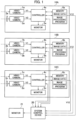
- the laser beam irradiation detection system includes laser beam irradiation detection devices 10A, 10B, and 10C, a system control device 20, and a monitor 21, as an example.
- the laser beam irradiation detection devices 10A to 10C are collectively referred to as a laser beam irradiation detection device 10.
- the laser beam irradiation detection device 10A includes a video camera 1a, a video camera 2a with a bandpass filter 3a mounted on the front, a controller 4a, a monitor 5a, and a memory 6a.
- a laser beam irradiation detection device 10B includes a video camera 1b, a video camera 2b with a bandpass filter 3b mounted on the front, a controller 4b, a monitor 5b, and a memory 6b.
- a laser beam irradiation detection device 10C includes a video camera 1c, a video camera 2c with a bandpass filter 3c mounted on the front, a controller 4c, a monitor 5c, and a memory 6c.
- the video cameras 1a, 1b, and 1c are collectively referred to as a video camera 1.
- the video cameras 2a, 2b, and 2c are collectively referred to as a video camera 2.
- the bandpass filters 3a, 3b, and 3c are collectively referred to as a bandpass filter 3.
- the controllers 4a, 4b, and 4c are collectively referred to as a controller 4.
- the monitors 5a, 5b, and 5c are collectively referred to as a monitor 5.
- the memories 6a, 6b, and 6c are collectively referred to as a memory 6.
- the video cameras 1 and 2 are normal video cameras capable of capturing an image of a visible light region, and may be commercially available consumer video cameras or business video cameras.
- the video camera 1 and the video camera 2 operate in synchronization and capture images of the same subject at the same angle of view.
- the video camera 1 roughly includes an imaging unit 111 including a lens and an imaging element, a video signal processing circuit 112 that generates a video signal based on an imaging signal output from the imaging unit 111, and a video output terminal 113 for outputting a video signal V1 to the outside.
- the video camera 2 includes an imaging unit 211, a video signal processing circuit 212 that generates a video signal based on an imaging signal output from the imaging unit 211, and a video output terminal 213 for outputting a video signal V2 to the outside.
- the video camera 1 and the video camera 2 have the same configuration, and the bandpass filter 3 is attached to the front of the lens of the video camera 2.
- the imaging unit 111 captures a light ray from a subject which does not pass through the bandpass filter 3, and the imaging unit 211 captures a light ray which passes through the bandpass filter 3.
- the light ray from the subject is a light ray reflected from the subject and may include a laser beam emitted from a laser beam source.
- the controller 4 is supplied with the video signals V1 and V2 output from the video output terminals 113 and 213.
- the bandpass filter 3 allows a light ray of a predetermined band including the wavelength band of the color of the laser beam, which is the target of the detection, among the light rays from the subject to pass therethrough and attenuates a light ray of other bands.
- laser beams to be irradiated due to mischief to a windshield or the like of a cockpit of an airplane are green laser beams. Therefore, it is preferable that a filter which allows a light ray in a band including the wavelength band of green color to pass therethrough be used as the bandpass filter 3.
- the bandpass filter 3 may be a filter which allows light ray in a band including the wavelength bands of green and red to pass therethrough.
- the controller 4 can be configured by a microprocessor.
- the controller 4 and the memory 6 may be microcomputers and the controller 4 may be a central processing unit (CPU).
- the monitor 5 is a liquid crystal panel which displays an image based on the video signal V1 or a synthesized video signal V12 described below, for example.
- the laser beam irradiation detection device 10 may not include the monitor 5.
- the memory 6 stores an image processing program and the controller 4 executes the image processing program.
- the memory 6 stores image data, which will be described below, generated by the controller 4 executing the image processing program.
- the system control device 20 can be configured by a personal computer.
- the system control device 20 controls the laser beam irradiation detection devices 10A to 10C.
- Various types of information to be described below are input from the controller 4 to the system control device 20 and image data (synthesized video signal V12) is input from the memory 6.
- the monitor 21 displays an image based on the image data input to the system control device 20. As illustrated in FIG. 3A , the monitor 21 may be configured by a multi-monitor consisting of monitors 21a, 21b, and 21c.
- the monitor 21a displays an image ImA based on the image data output from the laser beam irradiation detection device 10A.
- the monitor 21b displays an image ImB based on the image data output from the laser beam irradiation detection device 10B.
- the monitor 21c displays an image ImC based on the image data output from the laser beam irradiation detection device 10C.
- the monitor 21 may be a single monitor in which the system control device 20 displays an image based on synthesized image data obtained by synthesizing the image data from the laser beam irradiation detection devices 10A to 10C. In the embodiment, it is assumed that the monitor 21 is configured by the monitors 21a to 21c illustrated in FIG. 3A .
- the laser beam irradiation detection devices 10A to 10C are arranged in a cockpit 501 of an airplane 500 such that video cameras 1 and 2 capture the front of a windshield 502, as an example.
- the entire windshield and cockpit window is referred to as the windshield 502.
- the laser beam irradiation detection devices 10A to 10C are arranged to capture substantially the entire field of view in front of the windshield 502 while shifting the ranges captured by the video cameras 1 and 2.
- the system control device 20 and the monitor 21 may be arranged at any position in the cockpit 501 or may be arranged outside of the cockpit 501.
- the laser beam irradiation detection device 10 and the system control device 20 may be connected by wire or may be connected wirelessly.
- the controller 4 includes an image data writing and reading controller 41, an image synthesizing unit 42, a detector 43, and a position and direction information generator 47.
- the detector 43 includes a histogram generator 44, a light ray trajectory detector 45, and a determiner 46.
- the data writing and reading controller 41 supplies the memory 6 with the write or read control signal SCTL, writes the video signals V1 and V2 into the memory 6, and reads the video signals V1 and V2 from the memory 6.
- the image synthesizing unit 42 synthesizes the video signals V1 and V2 read from the memory 6 to generate a synthesized video signal V12.
- the synthesized video signal V12 is written to the memory 6 as image data.
- the synthesized video signal V12 read from the memory 6 is supplied to the system control device 20.
- the histogram generator 44 analyzes the frequency for each brightness level of the video signal V2 generated based on the image signal output from the imaging unit 211 and generates a histogram.
- the histogram illustrated in FIG. 6 includes a peak 440 at which the frequency protrudes at a specific brightness level on a high luminance side. The histogram is supplied to the determiner 46.
- the light ray trajectory detector 45 detects whether a straight light ray trajectory exists in a frame of the video signal V2.
- a trajectory 450 of the straight light ray exists in a frame F2.
- a part of the trajectory 450 which is the portion illustrated by a dashed line, is a tip side in an advancing direction of the light ray and indicates that the luminance thereof is smaller than that near the laser beam source.
- the light ray trajectory detector 45 determines that the trajectory 450 is a straight line.
- the light ray trajectory detector 45 can detect, based on the determination result, whether a straight light ray trajectory exists in the frame F2.
- the determiner 46 determines that the trajectory is the trajectory of the light ray formed by the irradiation of the laser beam, and the windshield 502 is irradiated with the laser beam.
- the position and direction information generator 47 When it is determined by the determiner 46 that the windshield 502 is irradiated with the laser beam, the position and direction information generator 47 generates emission position information indicating the emission position of the laser beam or emission position direction information indicating the direction of the emission position as follows.
- the position and direction information generator 47 operates as an emission position detector and an emission position direction estimating unit.
- FIG. 8 illustrates a case where the laser beam emission position (that is, the position of the laser beam source) exists within the angle of view of the video camera 2.
- a first end portion 451 and a second end portion 452 of the trajectory 450 of the laser beam are located inside the frame F2.
- the second end portion 452 may be located at an end portion of the frame F2, not inside the frame F2.
- the position and direction information generator 47 detects the first end portion 451 as the laser beam emission position.
- the position and direction information generator 47 generates and outputs laser beam emission position information.
- a person carrying a laser beam source may shake the laser beam source. Therefore, while the bright spot on the first end portion 451 side is unlikely to move, the bright spot on the second end portion 452 side may move in an arc shape.
- the position and direction information generator 47 may detect the first end portion 451 as the laser beam emission position. In this way, it is possible to improve the detection accuracy of the laser beam emission position.
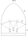
- FIG. 9 illustrates a case where the laser beam emission position does not exist within the angle of view of the video camera 2.
- the first end portion 451 is located at a left end portion FLe of the frame F2 and the second end portion 452 is located at a lower end portion FBe of the frame F2.
- the second end portion 452 may be located inside the frame F2.
- the position and direction information generator 47 estimates that the laser beam emission position exists in a direction in which the trajectory 450 extends outward beyond the first end portion 451.
- the position and direction information generator 47 generates and outputs laser beam emission position direction information.
- the bright spot on the first end portion 451 side moves only in a small arc shape, while the bright spot on the second end portion 452 side moves largely in an arc shape.
- the position and direction information generator 47 may estimate that the laser beam emission position exists in a direction in which the trajectory 450 extends outward beyond the first end portion 451. In this way, it is possible to improve the estimation accuracy of the laser beam emission position direction.
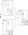
- FIG. 10 conceptually illustrates a synthesized frame F12 of the synthesized video signal V12 generated by the image synthesizing unit 42 synthesizing the frame F1 of the video signal V1 and the frame F2 of the video signal V2.
- the frame F1 shows a normal view of an airfield captured by the video camera 1.
- the frame F2 shows a view in a state in which the trajectory 450 by the laser beam is clearly captured by the video camera 2 imaging the light ray which passes through the bandpass filter 3.
- the light ray in a band other than the pass band of the bandpass filter 3 is attenuated, so it is difficult to determine where in the view the emission position (first end portion 451) of the laser beam or the emission position direction is located.
- the image synthesizing unit 42 By the image synthesizing unit 42 generating the synthesized frame F12, which is a synthesized image, it is possible to superimpose the trajectory 450 by the laser beam on the normal view captured by the video camera 1. By watching the synthesized frame F12 displayed on the monitor 21, a monitoring person can easily determine where the laser beam emission position or the emission position direction is located in the view.
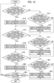
- the laser beam irradiation detection device 10 determines in step S1 whether the trajectory 450 of the laser beam is detected. When the trajectory 450 of the laser beam is not detected (NO), the laser beam irradiation detection device 10 repeats the process of step S1.
- the laser beam irradiation detection device 10 determines in step S2 whether the laser beam emission position exists within the angle of view. When the laser beam emission position exists within the angle of view (YES), the laser beam irradiation detection device 10 transmits the emission position information to the system control device 20 in step S3 and shifts the process to step S6.
- the laser beam irradiation detection device 10 determines in step S4 whether the direction of the laser beam emission position can be estimated. When the direction of the laser beam emission position can be estimated (YES), the laser beam irradiation detection device 10 transmits the emission position direction information to the system control device 20 in step S5 and shifts the process to step S6. When the direction of the laser beam emission position cannot be estimated (NO), the laser beam irradiation detection device 10 shifts the process to step S6.
- step S6 the laser beam irradiation detection device 10 determines whether the end of the laser beam irradiation detection process is instructed. When the end of the laser beam irradiation detection process is not instructed (NO), the laser beam irradiation detection device 10 returns the process to step S1 and repeats the processes of steps S1 to S6. When the end of the laser beam irradiation detection process is instructed (YES), the laser beam irradiation detection device 10 ends the process.
- the system control device 20 determines in step S11 whether the emission position information is received from the laser beam irradiation detection device 10A.
- the system control device 20 causes the monitor 21a to display an icon (identification image) indicating the emission position in step S12 and shifts the process to step S15.
- the system control device 20 determines in step S13 whether the emission position direction information is received from the laser beam irradiation detection device 10A.
- the system control device 20 causes the monitor 21a to display an icon indicating the emission position direction in step S14 and shifts the process to step S15.
- step S13 When the emission position direction information is not received from the laser beam irradiation detection device 10A in step S13 (NO), the system control device 20 shifts the process to step S15.
- the system control device 20 determines in step S15 whether the emission position information is received from the laser beam irradiation detection device 10B.
- the system control device 20 causes the monitor 21b to display an icon indicating the emission position in step 16 and shifts the process to step S19.
- the system control device 20 determines in step S17 whether the emission position direction information is received from the laser beam irradiation detection device 10B.
- the system control device 20 causes the monitor 21b to display an icon indicating the emission position direction in step S18 and shifts the process to step S19.
- step S17 When the emission position direction information is not received from the laser beam irradiation detection device 10B in step S17 (NO), the system control device 20 shifts the process to step S19.
- the system control device 20 determines in step S19 whether the emission position information is received from the laser beam irradiation detection device 10C.
- the system control device 20 causes the monitor 21c to display an icon indicating the emission position in step 20 and shifts the process to step S23.
- the system control device 20 determines in step S21 whether the emission position direction information is received from the laser beam irradiation detection device 10C.
- the system control device 20 causes the monitor 21c to display an icon indicating the emission position direction in step S22 and shifts the process to step S23.
- the system control device 20 shifts the process to step S23.
- step S23 the system control device 20 determines whether the end of the display process of the laser beam irradiation detection result is instructed. When the end of the display process is not instructed (NO), the system control device 20 returns the process to step S11 and repeats the processes of steps S11 to S23. When the end of the display process is instructed (YES), the system control device 20 ends the process.
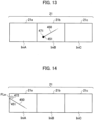
- FIG. 13 illustrates a state where the laser beam irradiation detection device 10B detects that the laser beam emission position exists within the angle of view by the process illustrated in FIG. 11 and the system control device 20 causes the monitor 21b to display an icon 471 indicating the emission position by the process illustrated in FIG 12 .
- the illustration of the landscape is omitted for the sake of simplicity.
- FIG. 13 illustrates an example in which the icon 471 of a circular shape is overlapped and displayed on the first end portion 451 which is the laser beam emission position.
- the icon 471 is not limited to a circle shape and the icon 471 may be displayed so as not to overlap with the first end portion 451.
- FIG. 14 illustrates a state where the laser beam irradiation detection device 10A detects that there is a laser beam trajectory 450 although the laser beam emission position does not exist within the angle of view by the process illustrated in FIG. 11 , and the system control device 20 causes the monitor 21a to display an icon 472 indicating the emission position direction by the process illustrated in FIG. 12 .
- the illustration of the landscape is omitted for the sake of simplicity.
- the system control device 20 has the icon 472 with an arrow pointing in a direction in which the trajectory 450 is extended to the left.
- the icon 472 is not limited to an arrow.
- the system control device 20 can detect the inclination of the trajectory 450, the inclination of the icon 472 can be displayed according to the inclination of the trajectory 450.
- the laser beam irradiation detection device the laser beam irradiation detection method, and the laser beam irradiation detection system according to the embodiment, it can be detected that the laser beam is irradiated to a predetermined target object such as the windshield of the cockpit of an airplane.
- the laser beam irradiation detection device the laser beam irradiation detection method, and the laser beam irradiation detection system according to the embodiment, the emission position or the emission position direction of the laser beam can be detected.
- a monitoring person can easily recognize the emission position or the emission position direction of the laser beam by the image displayed on the monitor 21.
- the laser beam irradiation detection device 10 is configured using existing video cameras 1 and 2. However, the laser beam irradiation detection device may be configured by improving the internal configuration of the video camera.
- a video camera 100 illustrated in FIG. 15 configures a laser beam irradiation detection device.
- a light ray from a subject is incident on an imaging element 102 through one or a plurality of lenses 101 and is imaged.
- a video signal processing circuit 103 generates a video signal V1 based on the imaging signal from the imaging element 102.
- a light ray from a subject is incident on an imaging element 106 through a bandpass filter 104 and one or a plurality of lenses 105 and is imaged. Similar to the bandpass filter 3, the bandpass filter 104 allows a light ray of a predetermined band including the wavelength band of the color of the laser beam, which is the target of the detection, among the light rays from the subject to pass therethrough, and attenuates the light ray of the other band.
- the video signal processing circuit 107 generates a video signal V2 based on the imaging signal from the imaging element 106.
- the operation of the controller 108, the monitor 109, and the memory 110 is similar to that of the controller 4, the monitor 5, and the memory 6.
- the monitor 109 can be omitted.
- the controller 4 by executing an image processing program, the controller 4 generates the histogram of the video signal V2, detects the existence of the trajectory of the straight light ray, and determines whether the target object is irradiated with a laser beam.
- the configuration for executing those operations may be realized by hardware.
- the use of hardware and software in the configuration of the laser beam irradiation detection device 10 or the laser beam irradiation detection system is optional.
- a target object for detecting the irradiation of the laser beam is not limited to the windshield of the cockpit of the airplane or the like.
- the target object may be an automobile, a player playing sports, or the like.
- three laser beam irradiation detection devices 10 are used, but an appropriate number of laser beam irradiation detection devices 10 may be used according to the range of the target object for detecting the irradiation of the laser beam.
- the laser beam irradiation detection devices 10 may be arranged so as to monitor a 360-degree range around a predetermined point.
Landscapes
- Physics & Mathematics (AREA)
- Engineering & Computer Science (AREA)
- Electromagnetism (AREA)
- Plasma & Fusion (AREA)
- General Physics & Mathematics (AREA)
- Health & Medical Sciences (AREA)
- Chemical & Material Sciences (AREA)
- Optics & Photonics (AREA)
- Aviation & Aerospace Engineering (AREA)
- General Health & Medical Sciences (AREA)
- Biochemistry (AREA)
- Analytical Chemistry (AREA)
- Immunology (AREA)
- Pathology (AREA)
- Life Sciences & Earth Sciences (AREA)
- Remote Sensing (AREA)
- Radar, Positioning & Navigation (AREA)
- Signal Processing (AREA)
- Multimedia (AREA)
- Nuclear Medicine, Radiotherapy & Molecular Imaging (AREA)
- Combustion & Propulsion (AREA)
- Studio Devices (AREA)
- Testing Or Calibration Of Command Recording Devices (AREA)
Claims (5)
- Vorrichtung (10A, 10B oder 10C) zum Detektieren einer Einstrahlung eines Laserstrahls, aufweisend:einen Bandpassfilter (3a, 3b oder 3c), der konfiguriert ist, um es einem Lichtstrahl eines vorbestimmten Bands, das ein Wellenlängenband einer Farbe eines Laserstrahls enthält, der ein Detektionsziel ist, unter Lichtstrahlen von einem Subjekt zu erlauben, dort hindurchzugehen;eine Bildgebungseinheit (211), die konfiguriert ist, um den Lichtstrahl, der durch den Bandpassfilter (3a, 3b oder 3c) durchgeht, abzubilden; und gekennzeichnet durcheinen Histogrammgenerator (44), der konfiguriert ist, um ein Histogramm durch Analysieren einer Frequenz für jeden Helligkeitspegel eines Videosignals zu erzeugen, das basierend auf einem Bildgebungssignal erzeugt wird, das von der Bildgebungseinheit ausgegeben wird, um einen Peak zu detektieren, bei dem die Frequenz bei einem spezifischen Helligkeitspegel hervorsteht;einen Lichtstrahltrajektoriendetektor (45), der konfiguriert ist, um eine Trajektorie eines Lichtstrahls in einem Rahmen des Videosignals zu detektieren, und um zu detektieren, dass die Trajektorie des Lichtstrahls eine Trajektorie eines geraden Lichtstrahls ist, wenn drei beliebige helle Punkte Pa, Pb und Pc auf der Trajektorie des Lichtstrahls ax+by+c=0 mit a, b und c als Konstanten und x und y als Variablen erfüllen;einen Bestimmer (46), der konfiguriert ist, um zu bestimmen, dass die Trajektorie die Trajektorie eines Lichtstrahls ist, der durch die Einstrahlung eines Laserstrahls gebildet wird, wenn der Peak, der durch den Histogrammgenerator (44) detektiert wird, bei dem spezifischen Helligkeitspegel des Histogramms vorhanden ist, und eine Trajektorie eines geraden Lichtstrahls in dem Rahmen vorhanden ist; undeinen Emissionspositionsdetektor (47), der konfiguriert ist, um zu detektieren, dass ein erster Endabschnitt der Trajektorie des geraden Lichtstrahls eine Laserstrahlemissionsposition ist, wenn der erste Endabschnitt in dem Rahmen vorhanden ist, ein Helligkeitspegel von der Seite des ersten Endabschnitts zu einer Seite des zweiten Endabschnitts abnimmt, wobei sich der zweite Endabschnitt in dem Rahmen oder an einem Endabschnitt des Rahmens befindet, und eine Bedingung, dass sich ein heller Punkt auf der Seite des zweiten Endabschnitts in einer Bogenform bewegt, erfüllt ist.
- Vorrichtung (10A, 10B oder 10C) zum Detektieren einer Einstrahlung eines Laserstrahls nach Anspruch 1, ferner aufweisend eine Emissionspositionsrichtungsschätzeinheit (47), die konfiguriert ist, um zu schätzen, dass eine Laserstrahlemissionsposition in einer Richtung vorhanden ist, in der sich die Trajektorie des geraden Lichtstrahls über den ersten Endabschnitt hinaus nach außen erstreckt, wenn sich der erste Endabschnitt an einem Endabschnitt des Rahmens befindet, ein Helligkeitspegel von der Seite des ersten Endabschnitts zu einer Seite des zweiten Endabschnitts abnimmt, und die Bedingung, dass sich ein heller Punkt auf der Seite des zweiten Endabschnitts mehr in einer Bogenform bewegt als der helle Punkt auf dem ersten Endabschnitt, erfüllt ist.
- Verfahren zum Detektieren einer Einstrahlung eines Laserstrahls, aufweisend:Erlauben, dass ein Lichtstrahl eines vorbestimmten Bands, das ein Wellenlängenband einer Farbe eines Laserstrahls enthält, der ein Detektionsziel ist, unter Lichtstrahlen von einem Subjekt hindurchgeht, und Dämpfen von Lichtstrahlen in anderen Bändern mit einem Bandpassfilter (3a, 3b oder 3c);Abbilden des Lichtstrahls des vorbestimmten Bands mit einer Bildgebungseinheit (211);Erzeugen eines Histogramms durch Analysieren einer Frequenz für jeden Helligkeitspegel eines Videosignals, das basierend auf einem Bildgebungssignal erzeugt wird, das von der Bildgebungseinheit (211) ausgegeben wird, und Detektieren eines Peaks, bei dem die Frequenz bei einem spezifischen Helligkeitspegel hervorsteht;Detektieren einer Trajektorie eines Lichtstrahls in einem Rahmen des Videosignals, und Detektieren, dass die Trajektorie des Lichtstrahls eine Trajektorie eines geraden Lichtstrahls ist, wenn drei beliebige helle Punkte Pa, Pb und Pc auf der Trajektorie des Lichtstrahls ax+by+c=0 mit a, b und c als Konstanten und x und y als Variablen erfüllen;Bestimmen, dass die Trajektorie die Trajektorie eines Lichtstrahls ist, der durch die Einstrahlung eines Laserstrahls gebildet wird, wenn der detektierte Peak bei dem spezifischen Helligkeitspegel des Histogramms vorhanden ist, und eine Trajektorie eines geraden Lichtstrahls in dem Rahmen vorhanden ist; undDetektieren, dass ein erster Endabschnitt der Trajektorie des geraden Lichtstrahls eine Laserstrahlemissionsposition ist, wenn der erste Endabschnitt in dem Rahmen vorhanden ist, ein Helligkeitspegel von der Seite des ersten Endabschnitts zu einer Seite des zweiten Endabschnitts abnimmt, wobei sich der zweite Endabschnitt in dem Rahmen oder an einem Endabschnitt des Rahmens befindet, und eine Bedingung, dass sich ein heller Punkt auf der Seite des zweiten Endabschnitts in einer Bogenform bewegt, erfüllt ist.
- Verfahren zum Detektieren einer Einstrahlung eines Laserstrahls nach Anspruch 3, ferner aufweisend ein Schätzen, dass eine Laserstrahlemissionsposition in einer Richtung vorhanden ist, in der sich die Trajektorie des geraden Lichtstrahls nach außen über den ersten Endabschnitt hinaus erstreckt, wenn sich der erste Endabschnitt an einem Endabschnitt des Rahmens befindet, ein Helligkeitspegel von der Seite des ersten Endabschnitts zu einer Seite des zweiten Endabschnitts abnimmt, und die Bedingung, dass sich ein heller Punkt auf der Seite des zweiten Endabschnitts mehr in einer Bogenform bewegt als der helle Punkt auf dem ersten Endabschnitt, erfüllt ist.
- System zum Detektieren einer Einstrahlung eines Laserstrahls, aufweisend:eine Vielzahl von Vorrichtungen (10A, 10B und 10C) zum Detektieren einer Einstrahlung eines Laserstrahls mit zueinander versetzten Bereichen zum Abbilden eines Subjekts;eine Systemsteuervorrichtung (20), der Bilddaten zugeführt werden, die von der Vielzahl von Vorrichtungen (10A, 10B und 10C) zum Detektieren einer Einstrahlung eines Laserstrahls ausgegeben werden; undeinen Monitor (21), der ein Bild basierend auf den Bilddaten anzeigt, die von der Vielzahl von Vorrichtungen (10A, 10B und 10C) zum Detektieren einer Einstrahlung eines Laserstrahls ausgegeben und der Systemsteuervorrichtung (20) zugeführt werden, und dadurch gekennzeichnet, dass;jede der Vielzahl von Vorrichtungen (10A, 10B oder 10C) zum Detektieren einer Einstrahlung eines Laserstrahls aufweist:eine Bildsynthetisierungseinheit (42), die konfiguriert ist zum Synthetisieren eines erstes Videosignals, das basierend auf einem ersten Bildgebungssignal erzeugt wird, das einen Lichtstrahl von einem Subjekt erfasst, und eines zweites Videosignals, das basierend auf einem zweiten Bildgebungssignal erzeugt wird, das einen Lichtstrahl erfasst, der erhalten wird, indem ein Lichtstrahl eines vorbestimmten Bands, das ein Wellenlängenband einer Farbe des Laserstrahls enthält, der ein Detektionsziel ist, unter Lichtstrahlen von dem Subjekt, dazu veranlasst wird, durch einen Bandpassfilter (3a, 3b oder 3c) hindurchzugehen, und um ein synthetisiertes Videosignal zu erzeugen;einen Histogrammgenerator (44), der konfiguriert ist, um ein Histogramm durch Analysieren einer Frequenz für jeden Helligkeitspegel des zweiten Videosignals zu erzeugen, um einen Peak zu detektieren, bei dem eine Frequenz bei einem spezifischen Helligkeitspegel hervorsteht;einen Lichtstrahltrajektoriendetektor (45), der konfiguriert ist, um eine Trajektorie eines Lichtstrahls in einem Rahmen des Videosignals zu detektieren, und um zu detektieren, dass die Trajektorie des Lichtstrahls eine Trajektorie eines geraden Lichtstrahls ist, wenn drei beliebige helle Punkte Pa, Pb und Pc auf der Trajektorie des Lichtstrahls ax+by+c=0 mit a, b und c als Konstanten und x und y als Variablen erfüllen;einen Bestimmer (46), der konfiguriert ist, um zu bestimmen, dass die Trajektorie die Trajektorie eines Lichtstrahls ist, der durch die Einstrahlung eines Laserstrahls gebildet wird, wenn der Peak, der durch den Histogrammgenerator (44) detektiert wird, bei dem spezifischen Helligkeitspegel des Histogramms vorhanden ist, und eine Trajektorie eines geraden Lichtstrahls in dem Rahmen vorhanden ist; undeinen Positions- und Richtungsinformationsgenerator (47), der konfiguriert ist, um zu detektieren, dass ein erster Endabschnitt der Trajektorie des geraden Lichtstrahls eine Laserstrahlemissionsposition ist, wenn der erste Endabschnitt in dem Rahmen vorhanden ist, ein Helligkeitspegel von der Seite des ersten Endabschnitts zu einer Seite des zweiten Endabschnitts abnimmt, wobei sich der zweite Endabschnitt in dem Rahmen oder an einem Endabschnitt des Rahmens befindet, und eine Bedingung, dass sich ein heller Punkt auf der Seite des zweiten Endabschnitts in einer Bogenform bewegt, erfüllt ist, um zu schätzen, dass eine Laserstrahlemissionsposition in einer Richtung vorhanden ist, in der sich die Trajektorie des geraden Lichtstrahls über den ersten Endabschnitt hinaus nach außen erstreckt, wenn sich der erste Endabschnitt an einem Endabschnitt des Rahmens befindet, ein Helligkeitspegel von der Seite des ersten Endabschnitts zu einer Seite des zweiten Endabschnitts abnimmt, und die Bedingung, dass sich ein heller Punkt auf der Seite des zweiten Endabschnitts in einer Bogenform bewegt, erfüllt ist, um Emissionspositionsinformationen zu erzeugen, die die Laserstrahlemissionsposition oder Emissionspositionsrichtungsinformationen angeben, die eine Emissionspositionsrichtung angeben, und um die Informationen der Systemsteuervorrichtung (20) zuzuführen, wenn bestimmt wird, dass die Trajektorie die Trajektorie eines Lichtstrahls ist, der durch die Einstrahlung eines Laserstrahls gebildet wird;und wobei die Systemsteuervorrichtung (20) konfiguriert ist, um auf dem Monitor (21) ein synthetisiertes Bild basierend auf dem synthetisierten Videosignal anzuzeigen, das von der Bildsynthetisierungseinheit (42) erzeugt wird, und um ein Identifikationsbild, das die Laserstrahlemissionsposition oder die Emissionspositionsrichtung angibt, auf dem synthetisierten Bild basierend auf den Emissionspositionsinformationen oder den Emissionspositionsrichtungsinformationen zu überlagern und anzuzeigen.
Applications Claiming Priority (2)
| Application Number | Priority Date | Filing Date | Title |
|---|---|---|---|
| JP2017041441A JP6774603B2 (ja) | 2017-03-06 | 2017-03-06 | レーザ光照射検出装置、レーザ光照射検出方法、レーザ光照射検出システム |
| PCT/JP2017/036300 WO2018163489A1 (ja) | 2017-03-06 | 2017-10-05 | レーザ光照射検出装置、レーザ光照射検出方法、及びレーザ光照射検出システム |
Publications (3)
| Publication Number | Publication Date |
|---|---|
| EP3594633A1 EP3594633A1 (de) | 2020-01-15 |
| EP3594633A4 EP3594633A4 (de) | 2020-03-18 |
| EP3594633B1 true EP3594633B1 (de) | 2023-11-15 |
Family
ID=63448521
Family Applications (1)
| Application Number | Title | Priority Date | Filing Date |
|---|---|---|---|
| EP17899963.7A Active EP3594633B1 (de) | 2017-03-06 | 2017-10-05 | Laserstrahlbestrahlungsdetektionsvorrichtung, laserstrahlbestrahlungsdetektionsverfahren und laserstrahlbestrahlungsdetektionssystem |
Country Status (5)
| Country | Link |
|---|---|
| US (1) | US11165217B2 (de) |
| EP (1) | EP3594633B1 (de) |
| JP (1) | JP6774603B2 (de) |
| CN (1) | CN110073175B (de) |
| WO (1) | WO2018163489A1 (de) |
Families Citing this family (4)
| Publication number | Priority date | Publication date | Assignee | Title |
|---|---|---|---|---|
| TWI767179B (zh) * | 2019-01-24 | 2022-06-11 | 宏達國際電子股份有限公司 | 混合實境中偵測真實世界光源的方法、混合實境系統及記錄媒體 |
| JP7408303B2 (ja) * | 2019-06-18 | 2024-01-05 | 株式会社ミツトヨ | 測定装置 |
| WO2022004207A1 (ja) * | 2020-06-30 | 2022-01-06 | オムロン株式会社 | レーザ加工システム |
| US12460968B2 (en) | 2020-09-18 | 2025-11-04 | MicroAdventure Technologies | Lensless imager for laser detection |
Family Cites Families (32)
| Publication number | Priority date | Publication date | Assignee | Title |
|---|---|---|---|---|
| US3698816A (en) * | 1970-09-16 | 1972-10-17 | Bell Telephone Labor Inc | Laser guidance system |
| SE9100916L (sv) * | 1991-03-27 | 1992-09-28 | Nobeltech Electronics Ab | Laservarnare |
| US5914661A (en) * | 1996-01-22 | 1999-06-22 | Raytheon Company | Helmet mounted, laser detection system |
| US6101333A (en) * | 1997-08-14 | 2000-08-08 | Polaroid Corporation | Method and apparatus for acquiring electronic and/or photographic images |
| JP3812159B2 (ja) * | 1998-07-29 | 2006-08-23 | 三菱電機株式会社 | 赤外線検出装置 |
| JP2000101177A (ja) * | 1998-09-18 | 2000-04-07 | Komatsu Ltd | エキシマレーザの波長計測システム及び中心波長の較正方法 |
| AU2002211559A1 (en) * | 2000-10-10 | 2002-04-22 | The Johns Hopkins University | Apparatus and method for detecting the location, intensity and initiation time of an energy pulse |
| JP2004054105A (ja) | 2002-07-23 | 2004-02-19 | Sharp Corp | レーザポインタ |
| US7846028B2 (en) * | 2005-05-19 | 2010-12-07 | Shoot The Moon Products Ii, Llc | Lazer tag advanced |
| US7531775B1 (en) * | 2005-06-13 | 2009-05-12 | The United States Of America As Represented By The Administrator Of The National Aeronautics And Space Administration | Photometer for tracking a moving light source |
| US7429734B1 (en) * | 2006-11-29 | 2008-09-30 | Aculight Corporation | System and method for aircraft infrared countermeasures to missiles |
| US20170191314A1 (en) * | 2008-08-20 | 2017-07-06 | Foro Energy, Inc. | Methods and Systems for the Application and Use of High Power Laser Energy |
| JP5519308B2 (ja) * | 2010-02-05 | 2014-06-11 | ルネサスエレクトロニクス株式会社 | 半導体集積回路及びデータ処理システム |
| US9134174B2 (en) * | 2013-01-07 | 2015-09-15 | The Boeing Company | Laser detection and warning system |
| US9043146B2 (en) * | 2013-06-19 | 2015-05-26 | The Boeing Company | Systems and methods for tracking location of movable target object |
| IL227050A (en) * | 2013-06-19 | 2016-08-31 | Levy Benjamin | Sensor low power sensor |
| KR102651578B1 (ko) * | 2013-11-27 | 2024-03-25 | 매직 립, 인코포레이티드 | 가상 및 증강 현실 시스템들 및 방법들 |
| FR3017480B1 (fr) * | 2014-02-07 | 2017-09-08 | Thales Sa | Procede de detection et de classification d'evenements d'une scene |
| TWM484091U (zh) * | 2014-03-31 | 2014-08-11 | Unibase Information Corp | 具有稽核及影像同步功能的航空器導引系統、及其稽核與影像同步裝置 |
| JP6412709B2 (ja) * | 2014-04-02 | 2018-10-24 | オリンパス株式会社 | 観察画像取得システム |
| EP2980599A1 (de) * | 2014-08-01 | 2016-02-03 | Hilti Aktiengesellschaft | Trackingverfahren und Trackingsystem |
| DE112015003608T5 (de) * | 2014-08-05 | 2017-04-20 | Fujifilm Corporation | Abstandsmessvorrichtung, Abstandsmessverfahren und Abstandsmessprogramm |
| JP6110887B2 (ja) * | 2015-03-17 | 2017-04-05 | 浜松ホトニクス株式会社 | 重畳画像生成装置及び重畳画像生成装置の作動方法 |
| DE102015009353A1 (de) * | 2015-07-17 | 2017-03-02 | Diehl Bgt Defence Gmbh & Co. Kg | Verfahren zum Schützen eines Fahrzeugs vor einem Angriff durch einen Laserstrahl |
| CN105096325B (zh) * | 2015-08-05 | 2017-01-18 | 罗普特(厦门)科技集团有限公司 | 基于激光图像的水下设备检测系统 |
| TWI618110B (zh) | 2015-08-20 | 2018-03-11 | 日新離子機器股份有限公司 | 離子植入系統 |
| KR20180086198A (ko) * | 2015-11-25 | 2018-07-30 | 트리나미엑스 게엠베하 | 적어도 하나의 물체를 광학적으로 검출하기 위한 검출기 |
| WO2017095817A1 (en) * | 2015-11-30 | 2017-06-08 | Luminar Technologies, Inc. | Lidar system with distributed laser and multiple sensor heads and pulsed laser for lidar system |
| US20190008019A1 (en) * | 2015-12-21 | 2019-01-03 | Le Henaff Guy | Method of controlling a light intensity of a light source in a light network |
| US10228451B2 (en) * | 2016-05-10 | 2019-03-12 | Lockheed Martin Corporation | Aircraft laser detector |
| CN106441163B (zh) * | 2016-10-13 | 2019-11-26 | 中国科学院上海技术物理研究所 | 一种非接触式柱状物垂直度检测方法及装置 |
| US10527920B1 (en) * | 2018-06-14 | 2020-01-07 | Dhpc Technologies, Inc. | System, method and device for a high fidelity electro-optical simulator |
-
2017
- 2017-03-06 JP JP2017041441A patent/JP6774603B2/ja active Active
- 2017-10-05 EP EP17899963.7A patent/EP3594633B1/de active Active
- 2017-10-05 WO PCT/JP2017/036300 patent/WO2018163489A1/ja not_active Ceased
- 2017-10-05 CN CN201780077756.8A patent/CN110073175B/zh active Active
-
2019
- 2019-09-04 US US16/560,369 patent/US11165217B2/en active Active
Also Published As
| Publication number | Publication date |
|---|---|
| JP2018146384A (ja) | 2018-09-20 |
| WO2018163489A1 (ja) | 2018-09-13 |
| US11165217B2 (en) | 2021-11-02 |
| JP6774603B2 (ja) | 2020-10-28 |
| CN110073175B (zh) | 2022-02-18 |
| EP3594633A1 (de) | 2020-01-15 |
| US20190393670A1 (en) | 2019-12-26 |
| EP3594633A4 (de) | 2020-03-18 |
| CN110073175A (zh) | 2019-07-30 |
Similar Documents
| Publication | Publication Date | Title |
|---|---|---|
| US11165217B2 (en) | Laser beam irradiation detection device, laser beam irradiation detection method, and laser beam irradiation detection system | |
| US9609206B2 (en) | Image processing apparatus, method for controlling image processing apparatus and storage medium | |
| JPH02105087A (ja) | 物体の始動と飛行を識別する方法とその装置 | |
| US20040175040A1 (en) | Process and device for detecting fires bases on image analysis | |
| US20180137629A1 (en) | Processing apparatus, imaging apparatus and automatic control system | |
| CN109714533B (zh) | 电子设备 | |
| US6496593B1 (en) | Optical muzzle blast detection and counterfire targeting system and method | |
| CN110583014B (zh) | 利用激光探测与测距设备探测及定位入侵者的方法和系统 | |
| KR20160050755A (ko) | 전자 장치 및 그의 홍채 인식 방법 | |
| WO2018086050A1 (zh) | 深度图生成方法和基于该方法的无人机 | |
| JP2022059581A (ja) | アクティブ防護システム、及びアクティブ防護システムを動作させる方法 | |
| KR20150024169A (ko) | 영상 융합 시스템 및 그 방법 | |
| WO2018156970A1 (en) | Real-time detection of periodic motion systems and methods | |
| KR20140050240A (ko) | 영상처리기반의 피아식별시스템 및 이의 제어방법 | |
| US20150235400A1 (en) | External vision and/or weapon aiming system for military land vehicles and military naval units | |
| JP4096539B2 (ja) | 複合追尾センサ装置 | |
| JP6317914B2 (ja) | 車載画像処理装置 | |
| US10298826B2 (en) | Spatial isolation of energy associated with a scene | |
| US20110181722A1 (en) | Target identification method for a weapon system | |
| KR102251166B1 (ko) | 파노라마 관측 시스템 | |
| KR101546799B1 (ko) | 열 영상 카메라를 이용하는 발칸포용 야간조준기 및 그 방법 | |
| US9832401B1 (en) | Minimization of fixed pattern noise in images of moving scenes | |
| US20210325675A1 (en) | System and method for providing increased sensor field of view | |
| CN113108919B (zh) | 人体温度检测方法、装置和存储介质 | |
| KR20140095339A (ko) | 조준 정확도 분석 장치 및 방법 |
Legal Events
| Date | Code | Title | Description |
|---|---|---|---|
| STAA | Information on the status of an ep patent application or granted ep patent |
Free format text: STATUS: THE INTERNATIONAL PUBLICATION HAS BEEN MADE |
|
| PUAI | Public reference made under article 153(3) epc to a published international application that has entered the european phase |
Free format text: ORIGINAL CODE: 0009012 |
|
| STAA | Information on the status of an ep patent application or granted ep patent |
Free format text: STATUS: REQUEST FOR EXAMINATION WAS MADE |
|
| 17P | Request for examination filed |
Effective date: 20190905 |
|
| AK | Designated contracting states |
Kind code of ref document: A1 Designated state(s): AL AT BE BG CH CY CZ DE DK EE ES FI FR GB GR HR HU IE IS IT LI LT LU LV MC MK MT NL NO PL PT RO RS SE SI SK SM TR |
|
| AX | Request for extension of the european patent |
Extension state: BA ME |
|
| A4 | Supplementary search report drawn up and despatched |
Effective date: 20200217 |
|
| RIC1 | Information provided on ipc code assigned before grant |
Ipc: B64D 45/00 20060101ALI20200211BHEP Ipc: G01S 3/784 20060101ALI20200211BHEP Ipc: H01S 3/00 20060101ALI20200211BHEP Ipc: G01S 5/16 20060101ALI20200211BHEP Ipc: G01D 21/00 20060101AFI20200211BHEP |
|
| DAV | Request for validation of the european patent (deleted) | ||
| DAX | Request for extension of the european patent (deleted) | ||
| STAA | Information on the status of an ep patent application or granted ep patent |
Free format text: STATUS: EXAMINATION IS IN PROGRESS |
|
| 17Q | First examination report despatched |
Effective date: 20200921 |
|
| GRAP | Despatch of communication of intention to grant a patent |
Free format text: ORIGINAL CODE: EPIDOSNIGR1 |
|
| STAA | Information on the status of an ep patent application or granted ep patent |
Free format text: STATUS: GRANT OF PATENT IS INTENDED |
|
| INTG | Intention to grant announced |
Effective date: 20230609 |
|
| GRAS | Grant fee paid |
Free format text: ORIGINAL CODE: EPIDOSNIGR3 |
|
| GRAA | (expected) grant |
Free format text: ORIGINAL CODE: 0009210 |
|
| STAA | Information on the status of an ep patent application or granted ep patent |
Free format text: STATUS: THE PATENT HAS BEEN GRANTED |
|
| AK | Designated contracting states |
Kind code of ref document: B1 Designated state(s): AL AT BE BG CH CY CZ DE DK EE ES FI FR GB GR HR HU IE IS IT LI LT LU LV MC MK MT NL NO PL PT RO RS SE SI SK SM TR |
|
| REG | Reference to a national code |
Ref country code: CH Ref legal event code: EP Ref country code: GB Ref legal event code: FG4D |
|
| REG | Reference to a national code |
Ref country code: DE Ref legal event code: R096 Ref document number: 602017076631 Country of ref document: DE |
|
| REG | Reference to a national code |
Ref country code: IE Ref legal event code: FG4D |
|
| REG | Reference to a national code |
Ref country code: LT Ref legal event code: MG9D |
|
| REG | Reference to a national code |
Ref country code: NL Ref legal event code: MP Effective date: 20231115 |
|
| PG25 | Lapsed in a contracting state [announced via postgrant information from national office to epo] |
Ref country code: GR Free format text: LAPSE BECAUSE OF FAILURE TO SUBMIT A TRANSLATION OF THE DESCRIPTION OR TO PAY THE FEE WITHIN THE PRESCRIBED TIME-LIMIT Effective date: 20240216 |
|
| PG25 | Lapsed in a contracting state [announced via postgrant information from national office to epo] |
Ref country code: IS Free format text: LAPSE BECAUSE OF FAILURE TO SUBMIT A TRANSLATION OF THE DESCRIPTION OR TO PAY THE FEE WITHIN THE PRESCRIBED TIME-LIMIT Effective date: 20240315 |
|
| PG25 | Lapsed in a contracting state [announced via postgrant information from national office to epo] |
Ref country code: LT Free format text: LAPSE BECAUSE OF FAILURE TO SUBMIT A TRANSLATION OF THE DESCRIPTION OR TO PAY THE FEE WITHIN THE PRESCRIBED TIME-LIMIT Effective date: 20231115 |
|
| REG | Reference to a national code |
Ref country code: AT Ref legal event code: MK05 Ref document number: 1632158 Country of ref document: AT Kind code of ref document: T Effective date: 20231115 |
|
| PG25 | Lapsed in a contracting state [announced via postgrant information from national office to epo] |
Ref country code: NL Free format text: LAPSE BECAUSE OF FAILURE TO SUBMIT A TRANSLATION OF THE DESCRIPTION OR TO PAY THE FEE WITHIN THE PRESCRIBED TIME-LIMIT Effective date: 20231115 |
|
| PG25 | Lapsed in a contracting state [announced via postgrant information from national office to epo] |
Ref country code: AT Free format text: LAPSE BECAUSE OF FAILURE TO SUBMIT A TRANSLATION OF THE DESCRIPTION OR TO PAY THE FEE WITHIN THE PRESCRIBED TIME-LIMIT Effective date: 20231115 |
|
| PG25 | Lapsed in a contracting state [announced via postgrant information from national office to epo] |
Ref country code: ES Free format text: LAPSE BECAUSE OF FAILURE TO SUBMIT A TRANSLATION OF THE DESCRIPTION OR TO PAY THE FEE WITHIN THE PRESCRIBED TIME-LIMIT Effective date: 20231115 |
|
| PG25 | Lapsed in a contracting state [announced via postgrant information from national office to epo] |
Ref country code: NL Free format text: LAPSE BECAUSE OF FAILURE TO SUBMIT A TRANSLATION OF THE DESCRIPTION OR TO PAY THE FEE WITHIN THE PRESCRIBED TIME-LIMIT Effective date: 20231115 Ref country code: LT Free format text: LAPSE BECAUSE OF FAILURE TO SUBMIT A TRANSLATION OF THE DESCRIPTION OR TO PAY THE FEE WITHIN THE PRESCRIBED TIME-LIMIT Effective date: 20231115 Ref country code: IS Free format text: LAPSE BECAUSE OF FAILURE TO SUBMIT A TRANSLATION OF THE DESCRIPTION OR TO PAY THE FEE WITHIN THE PRESCRIBED TIME-LIMIT Effective date: 20240315 Ref country code: GR Free format text: LAPSE BECAUSE OF FAILURE TO SUBMIT A TRANSLATION OF THE DESCRIPTION OR TO PAY THE FEE WITHIN THE PRESCRIBED TIME-LIMIT Effective date: 20240216 Ref country code: ES Free format text: LAPSE BECAUSE OF FAILURE TO SUBMIT A TRANSLATION OF THE DESCRIPTION OR TO PAY THE FEE WITHIN THE PRESCRIBED TIME-LIMIT Effective date: 20231115 Ref country code: BG Free format text: LAPSE BECAUSE OF FAILURE TO SUBMIT A TRANSLATION OF THE DESCRIPTION OR TO PAY THE FEE WITHIN THE PRESCRIBED TIME-LIMIT Effective date: 20240215 Ref country code: AT Free format text: LAPSE BECAUSE OF FAILURE TO SUBMIT A TRANSLATION OF THE DESCRIPTION OR TO PAY THE FEE WITHIN THE PRESCRIBED TIME-LIMIT Effective date: 20231115 Ref country code: PT Free format text: LAPSE BECAUSE OF FAILURE TO SUBMIT A TRANSLATION OF THE DESCRIPTION OR TO PAY THE FEE WITHIN THE PRESCRIBED TIME-LIMIT Effective date: 20240315 |
|
| PG25 | Lapsed in a contracting state [announced via postgrant information from national office to epo] |
Ref country code: SE Free format text: LAPSE BECAUSE OF FAILURE TO SUBMIT A TRANSLATION OF THE DESCRIPTION OR TO PAY THE FEE WITHIN THE PRESCRIBED TIME-LIMIT Effective date: 20231115 Ref country code: RS Free format text: LAPSE BECAUSE OF FAILURE TO SUBMIT A TRANSLATION OF THE DESCRIPTION OR TO PAY THE FEE WITHIN THE PRESCRIBED TIME-LIMIT Effective date: 20231115 Ref country code: PL Free format text: LAPSE BECAUSE OF FAILURE TO SUBMIT A TRANSLATION OF THE DESCRIPTION OR TO PAY THE FEE WITHIN THE PRESCRIBED TIME-LIMIT Effective date: 20231115 Ref country code: NO Free format text: LAPSE BECAUSE OF FAILURE TO SUBMIT A TRANSLATION OF THE DESCRIPTION OR TO PAY THE FEE WITHIN THE PRESCRIBED TIME-LIMIT Effective date: 20240215 Ref country code: LV Free format text: LAPSE BECAUSE OF FAILURE TO SUBMIT A TRANSLATION OF THE DESCRIPTION OR TO PAY THE FEE WITHIN THE PRESCRIBED TIME-LIMIT Effective date: 20231115 Ref country code: HR Free format text: LAPSE BECAUSE OF FAILURE TO SUBMIT A TRANSLATION OF THE DESCRIPTION OR TO PAY THE FEE WITHIN THE PRESCRIBED TIME-LIMIT Effective date: 20231115 |
|
| PG25 | Lapsed in a contracting state [announced via postgrant information from national office to epo] |
Ref country code: DK Free format text: LAPSE BECAUSE OF FAILURE TO SUBMIT A TRANSLATION OF THE DESCRIPTION OR TO PAY THE FEE WITHIN THE PRESCRIBED TIME-LIMIT Effective date: 20231115 |
|
| PG25 | Lapsed in a contracting state [announced via postgrant information from national office to epo] |
Ref country code: CZ Free format text: LAPSE BECAUSE OF FAILURE TO SUBMIT A TRANSLATION OF THE DESCRIPTION OR TO PAY THE FEE WITHIN THE PRESCRIBED TIME-LIMIT Effective date: 20231115 |
|
| PG25 | Lapsed in a contracting state [announced via postgrant information from national office to epo] |
Ref country code: SK Free format text: LAPSE BECAUSE OF FAILURE TO SUBMIT A TRANSLATION OF THE DESCRIPTION OR TO PAY THE FEE WITHIN THE PRESCRIBED TIME-LIMIT Effective date: 20231115 |
|
| PG25 | Lapsed in a contracting state [announced via postgrant information from national office to epo] |
Ref country code: SM Free format text: LAPSE BECAUSE OF FAILURE TO SUBMIT A TRANSLATION OF THE DESCRIPTION OR TO PAY THE FEE WITHIN THE PRESCRIBED TIME-LIMIT Effective date: 20231115 Ref country code: SK Free format text: LAPSE BECAUSE OF FAILURE TO SUBMIT A TRANSLATION OF THE DESCRIPTION OR TO PAY THE FEE WITHIN THE PRESCRIBED TIME-LIMIT Effective date: 20231115 Ref country code: RO Free format text: LAPSE BECAUSE OF FAILURE TO SUBMIT A TRANSLATION OF THE DESCRIPTION OR TO PAY THE FEE WITHIN THE PRESCRIBED TIME-LIMIT Effective date: 20231115 Ref country code: IT Free format text: LAPSE BECAUSE OF FAILURE TO SUBMIT A TRANSLATION OF THE DESCRIPTION OR TO PAY THE FEE WITHIN THE PRESCRIBED TIME-LIMIT Effective date: 20231115 Ref country code: EE Free format text: LAPSE BECAUSE OF FAILURE TO SUBMIT A TRANSLATION OF THE DESCRIPTION OR TO PAY THE FEE WITHIN THE PRESCRIBED TIME-LIMIT Effective date: 20231115 Ref country code: DK Free format text: LAPSE BECAUSE OF FAILURE TO SUBMIT A TRANSLATION OF THE DESCRIPTION OR TO PAY THE FEE WITHIN THE PRESCRIBED TIME-LIMIT Effective date: 20231115 Ref country code: CZ Free format text: LAPSE BECAUSE OF FAILURE TO SUBMIT A TRANSLATION OF THE DESCRIPTION OR TO PAY THE FEE WITHIN THE PRESCRIBED TIME-LIMIT Effective date: 20231115 |
|
| REG | Reference to a national code |
Ref country code: DE Ref legal event code: R097 Ref document number: 602017076631 Country of ref document: DE |
|
| PLBE | No opposition filed within time limit |
Free format text: ORIGINAL CODE: 0009261 |
|
| STAA | Information on the status of an ep patent application or granted ep patent |
Free format text: STATUS: NO OPPOSITION FILED WITHIN TIME LIMIT |
|
| 26N | No opposition filed |
Effective date: 20240819 |
|
| PG25 | Lapsed in a contracting state [announced via postgrant information from national office to epo] |
Ref country code: SI Free format text: LAPSE BECAUSE OF FAILURE TO SUBMIT A TRANSLATION OF THE DESCRIPTION OR TO PAY THE FEE WITHIN THE PRESCRIBED TIME-LIMIT Effective date: 20231115 |
|
| PG25 | Lapsed in a contracting state [announced via postgrant information from national office to epo] |
Ref country code: SI Free format text: LAPSE BECAUSE OF FAILURE TO SUBMIT A TRANSLATION OF THE DESCRIPTION OR TO PAY THE FEE WITHIN THE PRESCRIBED TIME-LIMIT Effective date: 20231115 |
|
| REG | Reference to a national code |
Ref country code: CH Ref legal event code: PL |
|
| GBPC | Gb: european patent ceased through non-payment of renewal fee |
Effective date: 20241005 |
|
| PG25 | Lapsed in a contracting state [announced via postgrant information from national office to epo] |
Ref country code: MC Free format text: LAPSE BECAUSE OF FAILURE TO SUBMIT A TRANSLATION OF THE DESCRIPTION OR TO PAY THE FEE WITHIN THE PRESCRIBED TIME-LIMIT Effective date: 20231115 |
|
| PG25 | Lapsed in a contracting state [announced via postgrant information from national office to epo] |
Ref country code: GB Free format text: LAPSE BECAUSE OF NON-PAYMENT OF DUE FEES Effective date: 20241005 |
|
| PG25 | Lapsed in a contracting state [announced via postgrant information from national office to epo] |
Ref country code: LU Free format text: LAPSE BECAUSE OF NON-PAYMENT OF DUE FEES Effective date: 20241005 Ref country code: BE Free format text: LAPSE BECAUSE OF NON-PAYMENT OF DUE FEES Effective date: 20241031 |
|
| PG25 | Lapsed in a contracting state [announced via postgrant information from national office to epo] |
Ref country code: FR Free format text: LAPSE BECAUSE OF NON-PAYMENT OF DUE FEES Effective date: 20241031 |
|
| PG25 | Lapsed in a contracting state [announced via postgrant information from national office to epo] |
Ref country code: CH Free format text: LAPSE BECAUSE OF NON-PAYMENT OF DUE FEES Effective date: 20241031 |
|
| REG | Reference to a national code |
Ref country code: BE Ref legal event code: MM Effective date: 20241031 |
|
| PG25 | Lapsed in a contracting state [announced via postgrant information from national office to epo] |
Ref country code: FI Free format text: LAPSE BECAUSE OF FAILURE TO SUBMIT A TRANSLATION OF THE DESCRIPTION OR TO PAY THE FEE WITHIN THE PRESCRIBED TIME-LIMIT Effective date: 20231115 |
|
| PG25 | Lapsed in a contracting state [announced via postgrant information from national office to epo] |
Ref country code: IE Free format text: LAPSE BECAUSE OF NON-PAYMENT OF DUE FEES Effective date: 20241005 |
|
| PGFP | Annual fee paid to national office [announced via postgrant information from national office to epo] |
Ref country code: DE Payment date: 20250902 Year of fee payment: 9 |
|
| PG25 | Lapsed in a contracting state [announced via postgrant information from national office to epo] |
Ref country code: CY Free format text: LAPSE BECAUSE OF FAILURE TO SUBMIT A TRANSLATION OF THE DESCRIPTION OR TO PAY THE FEE WITHIN THE PRESCRIBED TIME-LIMIT; INVALID AB INITIO Effective date: 20171005 |
|
| PG25 | Lapsed in a contracting state [announced via postgrant information from national office to epo] |
Ref country code: HU Free format text: LAPSE BECAUSE OF FAILURE TO SUBMIT A TRANSLATION OF THE DESCRIPTION OR TO PAY THE FEE WITHIN THE PRESCRIBED TIME-LIMIT; INVALID AB INITIO Effective date: 20171005 |