EP3594630B1 - Kompensation ungeradzahliger harmonischer verzerrung für drehmelder/lvdt - Google Patents
Kompensation ungeradzahliger harmonischer verzerrung für drehmelder/lvdt Download PDFInfo
- Publication number
- EP3594630B1 EP3594630B1 EP19185011.4A EP19185011A EP3594630B1 EP 3594630 B1 EP3594630 B1 EP 3594630B1 EP 19185011 A EP19185011 A EP 19185011A EP 3594630 B1 EP3594630 B1 EP 3594630B1
- Authority
- EP
- European Patent Office
- Prior art keywords
- winding
- fundamental frequency
- secondary winding
- primary winding
- voltage
- Prior art date
- Legal status (The legal status is an assumption and is not a legal conclusion. Google has not performed a legal analysis and makes no representation as to the accuracy of the status listed.)
- Active
Links
Images


Classifications
-
- G—PHYSICS
- G01—MEASURING; TESTING
- G01D—MEASURING NOT SPECIALLY ADAPTED FOR A SPECIFIC VARIABLE; ARRANGEMENTS FOR MEASURING TWO OR MORE VARIABLES NOT COVERED IN A SINGLE OTHER SUBCLASS; TARIFF METERING APPARATUS; MEASURING OR TESTING NOT OTHERWISE PROVIDED FOR
- G01D5/00—Mechanical means for transferring the output of a sensing member; Means for converting the output of a sensing member to another variable where the form or nature of the sensing member does not constrain the means for converting; Transducers not specially adapted for a specific variable
- G01D5/12—Mechanical means for transferring the output of a sensing member; Means for converting the output of a sensing member to another variable where the form or nature of the sensing member does not constrain the means for converting; Transducers not specially adapted for a specific variable using electric or magnetic means
- G01D5/14—Mechanical means for transferring the output of a sensing member; Means for converting the output of a sensing member to another variable where the form or nature of the sensing member does not constrain the means for converting; Transducers not specially adapted for a specific variable using electric or magnetic means influencing the magnitude of a current or voltage
- G01D5/20—Mechanical means for transferring the output of a sensing member; Means for converting the output of a sensing member to another variable where the form or nature of the sensing member does not constrain the means for converting; Transducers not specially adapted for a specific variable using electric or magnetic means influencing the magnitude of a current or voltage by varying inductance, e.g. by a movable armature
- G01D5/204—Mechanical means for transferring the output of a sensing member; Means for converting the output of a sensing member to another variable where the form or nature of the sensing member does not constrain the means for converting; Transducers not specially adapted for a specific variable using electric or magnetic means influencing the magnitude of a current or voltage by varying inductance, e.g. by a movable armature by influencing the mutual induction between two or more coils
- G01D5/2073—Mechanical means for transferring the output of a sensing member; Means for converting the output of a sensing member to another variable where the form or nature of the sensing member does not constrain the means for converting; Transducers not specially adapted for a specific variable using electric or magnetic means influencing the magnitude of a current or voltage by varying inductance, e.g. by a movable armature by influencing the mutual induction between two or more coils by movement of a single coil with respect to two or more coils
-
- G—PHYSICS
- G01—MEASURING; TESTING
- G01D—MEASURING NOT SPECIALLY ADAPTED FOR A SPECIFIC VARIABLE; ARRANGEMENTS FOR MEASURING TWO OR MORE VARIABLES NOT COVERED IN A SINGLE OTHER SUBCLASS; TARIFF METERING APPARATUS; MEASURING OR TESTING NOT OTHERWISE PROVIDED FOR
- G01D5/00—Mechanical means for transferring the output of a sensing member; Means for converting the output of a sensing member to another variable where the form or nature of the sensing member does not constrain the means for converting; Transducers not specially adapted for a specific variable
- G01D5/12—Mechanical means for transferring the output of a sensing member; Means for converting the output of a sensing member to another variable where the form or nature of the sensing member does not constrain the means for converting; Transducers not specially adapted for a specific variable using electric or magnetic means
- G01D5/14—Mechanical means for transferring the output of a sensing member; Means for converting the output of a sensing member to another variable where the form or nature of the sensing member does not constrain the means for converting; Transducers not specially adapted for a specific variable using electric or magnetic means influencing the magnitude of a current or voltage
- G01D5/20—Mechanical means for transferring the output of a sensing member; Means for converting the output of a sensing member to another variable where the form or nature of the sensing member does not constrain the means for converting; Transducers not specially adapted for a specific variable using electric or magnetic means influencing the magnitude of a current or voltage by varying inductance, e.g. by a movable armature
- G01D5/22—Mechanical means for transferring the output of a sensing member; Means for converting the output of a sensing member to another variable where the form or nature of the sensing member does not constrain the means for converting; Transducers not specially adapted for a specific variable using electric or magnetic means influencing the magnitude of a current or voltage by varying inductance, e.g. by a movable armature differentially influencing two coils
- G01D5/2291—Linear or rotary variable differential transformers (LVDTs/RVDTs) having a single primary coil and two secondary coils
-
- G—PHYSICS
- G01—MEASURING; TESTING
- G01D—MEASURING NOT SPECIALLY ADAPTED FOR A SPECIFIC VARIABLE; ARRANGEMENTS FOR MEASURING TWO OR MORE VARIABLES NOT COVERED IN A SINGLE OTHER SUBCLASS; TARIFF METERING APPARATUS; MEASURING OR TESTING NOT OTHERWISE PROVIDED FOR
- G01D3/00—Indicating or recording apparatus with provision for the special purposes referred to in the subgroups
- G01D3/028—Indicating or recording apparatus with provision for the special purposes referred to in the subgroups mitigating undesired influences, e.g. temperature, pressure
- G01D3/032—Indicating or recording apparatus with provision for the special purposes referred to in the subgroups mitigating undesired influences, e.g. temperature, pressure affecting incoming signal, e.g. by averaging; gating undesired signals
-
- G—PHYSICS
- G01—MEASURING; TESTING
- G01D—MEASURING NOT SPECIALLY ADAPTED FOR A SPECIFIC VARIABLE; ARRANGEMENTS FOR MEASURING TWO OR MORE VARIABLES NOT COVERED IN A SINGLE OTHER SUBCLASS; TARIFF METERING APPARATUS; MEASURING OR TESTING NOT OTHERWISE PROVIDED FOR
- G01D5/00—Mechanical means for transferring the output of a sensing member; Means for converting the output of a sensing member to another variable where the form or nature of the sensing member does not constrain the means for converting; Transducers not specially adapted for a specific variable
- G01D5/12—Mechanical means for transferring the output of a sensing member; Means for converting the output of a sensing member to another variable where the form or nature of the sensing member does not constrain the means for converting; Transducers not specially adapted for a specific variable using electric or magnetic means
- G01D5/244—Mechanical means for transferring the output of a sensing member; Means for converting the output of a sensing member to another variable where the form or nature of the sensing member does not constrain the means for converting; Transducers not specially adapted for a specific variable using electric or magnetic means influencing characteristics of pulses or pulse trains; generating pulses or pulse trains
- G01D5/24471—Error correction
-
- G—PHYSICS
- G01—MEASURING; TESTING
- G01D—MEASURING NOT SPECIALLY ADAPTED FOR A SPECIFIC VARIABLE; ARRANGEMENTS FOR MEASURING TWO OR MORE VARIABLES NOT COVERED IN A SINGLE OTHER SUBCLASS; TARIFF METERING APPARATUS; MEASURING OR TESTING NOT OTHERWISE PROVIDED FOR
- G01D5/00—Mechanical means for transferring the output of a sensing member; Means for converting the output of a sensing member to another variable where the form or nature of the sensing member does not constrain the means for converting; Transducers not specially adapted for a specific variable
- G01D5/12—Mechanical means for transferring the output of a sensing member; Means for converting the output of a sensing member to another variable where the form or nature of the sensing member does not constrain the means for converting; Transducers not specially adapted for a specific variable using electric or magnetic means
- G01D5/244—Mechanical means for transferring the output of a sensing member; Means for converting the output of a sensing member to another variable where the form or nature of the sensing member does not constrain the means for converting; Transducers not specially adapted for a specific variable using electric or magnetic means influencing characteristics of pulses or pulse trains; generating pulses or pulse trains
- G01D5/24471—Error correction
- G01D5/24476—Signal processing
-
- H—ELECTRICITY
- H01—ELECTRIC ELEMENTS
- H01F—MAGNETS; INDUCTANCES; TRANSFORMERS; SELECTION OF MATERIALS FOR THEIR MAGNETIC PROPERTIES
- H01F21/00—Variable inductances or transformers of the signal type
- H01F21/02—Variable inductances or transformers of the signal type continuously variable, e.g. variometers
- H01F21/06—Variable inductances or transformers of the signal type continuously variable, e.g. variometers by movement of core or part of core relative to the windings as a whole
-
- H—ELECTRICITY
- H01—ELECTRIC ELEMENTS
- H01F—MAGNETS; INDUCTANCES; TRANSFORMERS; SELECTION OF MATERIALS FOR THEIR MAGNETIC PROPERTIES
- H01F27/00—Details of transformers or inductances, in general
- H01F27/28—Coils; Windings; Conductive connections
-
- H—ELECTRICITY
- H02—GENERATION; CONVERSION OR DISTRIBUTION OF ELECTRIC POWER
- H02K—DYNAMO-ELECTRIC MACHINES
- H02K11/00—Structural association of dynamo-electric machines with electric components or with devices for shielding, monitoring or protection
- H02K11/20—Structural association of dynamo-electric machines with electric components or with devices for shielding, monitoring or protection for measuring, monitoring, testing, protecting or switching
- H02K11/21—Devices for sensing speed or position, or actuated thereby
- H02K11/225—Detecting coils
-
- H—ELECTRICITY
- H02—GENERATION; CONVERSION OR DISTRIBUTION OF ELECTRIC POWER
- H02K—DYNAMO-ELECTRIC MACHINES
- H02K24/00—Machines adapted for the instantaneous transmission or reception of the angular displacement of rotating parts, e.g. synchro, selsyn
-
- H—ELECTRICITY
- H03—ELECTRONIC CIRCUITRY
- H03M—CODING; DECODING; CODE CONVERSION IN GENERAL
- H03M1/00—Analogue/digital conversion; Digital/analogue conversion
- H03M1/12—Analogue/digital converters
- H03M1/48—Servo-type converters
- H03M1/485—Servo-type converters for position encoding, e.g. using resolvers or synchros
Definitions
- the present disclosure relates to movable components in machinery, and more particularly, to determining the rotational position of rotating components in rotating machinery and the linear positon of linear components in linearly movable machinery.
- Resolvers are commonly used to determine the rotational position of rotating components in rotating machinery.
- resolvers are oftentimes associated with starter motor generators and actuators in aircraft to provide feedback regarding the state of the actuator, e.g., whether the actuator is open, partially open, or closed.
- a typical resolver includes an excitation coil carried by a rotating component that is rotatable relative to first and second secondary coils positioned 90-degrees out of phase with one another.
- a sinusoidal excitation signal supplied to the excitation coil induces corresponding output signals in the first and second secondary coils.
- the resolver output signals need to be sampled at rates that can approach the excitation frequency of the resolver.
- LVDTs linear voltage differential transformers
- a typical LVDT includes an excitation coil linearly centered between first and secondary coils connected 180-degrees out of phase with one another, and a linearly movable ferromagnetic core that alters the mutual inductive coupling between the primary and each of the two secondary coils.
- a system for determining an amplitude of a fundamental frequency of an electrical signal in the presence of odd harmonic frequencies includes a primary winding, a secondary winding, an excitation module electrically connected to the primary winding and configured to provide an excitation signal to the primary winding where the excitation signal is an alternating current waveform having the fundamental frequency, and a controller electrically conencted to the secondary winding and configured to sample a voltage across the secondary winding at 18 times the fundamental frequency and determine the amplitude of the fundamental frequency based on the sampled voltage across the secondary winding.
- a resolver system includes a rotatable primary winding, a fixed secondary winding fixed relative to the rotatable primary winding, a fixed tertiary winding fixed relative to the rotatable primary winding and positioned ⁇ /2 radians out of phase with respect to the fixed secondary winding, an excitation module electrically connected to the rotatable primary winding and configured to provide an excitation signal to the rotatable primary winding where the excitation signal is an alternating current waveform having a fundamental frequency, and a controller electrically connected to the fixed secondary winding and configured to sample a voltage across the secondary winding at 18 times the fundamental frequency, and to sample a voltage across the fixed tertiary winding at 18 times the fundamental frequency, and determine an amplitude of the fundamental frequency based on the sampled voltages across the fixed secondary and fixed tertiary windings, where the alternating current waveform includes a third harmonic frequency and the rotatable primary winding is mechanically connected to a rotatable component.
- a system for determining an amplitude of a fundamental frequency of an electrical signal in the presence of a third harmonic frequency and a fifth harmonic frequency includes a primary winding, a secondary winding, a tertiary winding, an excitation module electrically connected to the primary winding and configured to provide an excitation signal to the primary winding, where the excitation signal is an alternating current waveform having a fundamental frequency, and a controller electrically connected to the secondary and tertiary windings and configured to sample a voltage across the secondary and tertiary windings at 90 times the fundamental frequency and determine the amplitude of the fundamental frequency based on the sampled voltages across the secondary and tertiary windings, where the alternating current waveform includes a third harmonic frequency and a fifth harmonic frequency.
- a harmonic frequency can be referred to as a "harmonic".
- the second harmonic is twice the frequency of the fundamental frequency
- the third harmonic is three times the frequency of the fundamental frequency, and so on.
- Many instrumentation systems use a sinusoid waveform that contains harmonic frequencies of the fundamental frequency.
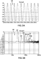
- the odd harmonic frequencies can be the most prevalent because of the method used to generate the sinusoid waveform. Therefore, under some conditions, the odd harmonics can impair the accuracy of the rotational position that is sensed by the resolver, or the linear position that is sensed by the LVDT. Exemplary values of the harmonics, and in particular the odd harmonics, will be described in FIGS. 3A and 3B .
- U.S. Patent Application Publication No. 2017/0299409A1 discloses a resolver system that acquires, or samples, voltages on the secondary windings at time intervals corresponding to ⁇ /3 radians (60 deg.) of the excitation voltage oscillating waveform. Stated alternatively, the sampling rate is exactly six times the excitation waveform frequency.
- FIG. 1 is a schematic block diagram of a resolver system. Shown in FIG. 1 are rotating component 8, resolver system 10, excitation module 12, winding module 14, interface module 16, primary winding 18, first secondary winding 20, second secondary winding 22, first buffer 26, first analog-to-digital converter (ADC) 28, second buffer 30, second ADC 32, output 48, and controller 50.
- Winding module 14 includes primary winding 18, first secondary winding 20, and second secondary winding 22.
- Primary winding 18 is fixed to rotating component 8, which can be, for example, a shaft in a gas turbine engine.
- Primary winding 18 is electrically connected to excitation module 12.
- rotating component 8 can be a shaft, dial, rotor, and so on, and can be any rotating mechanism on any system or component.
- Non-limiting examples of rotating component 8 include crankshafts on internal and external combustion engines, shafts on electromechanical machines, synchros, gyrocompasses, and dial indicators.
- first secondary winding 20 and second secondary winding 22 are fixed relative to primary winding 18, and are electromagnetically coupled to primary winding 18.
- primary winding 18 is rotatable, whereas first secondary winding 20 and second secondary winding 22 are stationary.
- First secondary winding 20 and second secondary winding 22 are positioned ⁇ /2 radians (90 deg.) out of phase with respect to each other.
- First secondary winding 20 and second secondary winding 22 are both electrically connected to interface module 16.
- Excitation module 12 is electrically connected to primary winding 18 and is configured to generate an excitation voltage of oscillating magnitude having a period defined by controller 50.
- controller 50 can be referred to as a control module.
- excitation module 12 applies an excitation voltage to primary winding 18 with a waveform having a sinusoidal shape and frequency f.
- the excitation voltage induces a first secondary voltage in first secondary winding 20 and a second secondary voltage in second secondary winding 22.
- Interface module 16 includes first buffer 26, first ADC 28, second buffer 30, and second ADC 32.
- First buffer 26 is electrically connected to first secondary winding 20 and receives voltage from first secondary winding 20.
- An ADC can also be referred to as a high-speed ADC.
- First buffer 26 is electrically connected to first ADC 28, which acquires periodic voltage measurements therefrom according to a sampling scheme defined by controller 50.
- first ADC 28 acquires, or samples, the voltage on first secondary winding 20 at time intervals corresponding to ⁇ /9 radians (20 deg.) of the excitation voltage waveform.
- first ADC 28 has a sampling rate of exactly 18 times the excitation waveform frequency f.
- second buffer 30 is electrically connected to second secondary winding 22 and receives voltage from second secondary winding 22.
- Second buffer 30 is electrically connected to second ADC 32, which acquires periodic voltage measurements therefrom according to a sampling scheme defined by controller 50.
- second ADC 32 acquires, or samples, the voltage on second secondary winding 22 at time intervals corresponding to ⁇ /9 radians (20 deg.) of the excitation voltage waveform.
- second ADC 32 has a sampling rate that is exactly 18 times the excitation waveform frequency f.
- First ADC 28 is electrically connected to control module 50 through first output lead 40 and first input lead 42. Based on a sampling scheme received from controller 50 through input lead 42, first ADC 28 provides periodic voltage measurements to control module 50 through first output lead 40.
- Second ADC 32 is similar to first ADC 28 with the difference that second ADC 32 is electrically connected to controller 50 through second output lead 44 and second input lead 46. Based on the sampling scheme received from controller 50 through input lead 46, second ADC 32 also provides periodic voltage measurements to controller 50 through output lead 44.
- Control module 50 receives the voltage measurements from first ADC 28 and second ADC 32, and provides an output voltage at resolver output terminal 48 that corresponds to the rotational position of primary winding 18, and therefore, the rotational position ⁇ of shaft 8.
- the output voltage at terminal 48 is a root mean square (RMS) voltage.
- Controller 50 causes first ADC 28 and second ADC 32 to acquire at least nine voltage measurements within one-half the period of the excitation waveform. Each of the at least nine voltage measurements is offset from another of the at least nine voltage measurements by ⁇ /9 radians (20 deg.) of one-half the period of the excitation waveform.
- a second voltage measurement occurs ⁇ /9 radians (20 deg.) after a first voltage measurement
- a third voltage measurement occurs ⁇ /9 radians (20 deg.) after a second voltage measurement, and so on.
- the sampling of voltages at first secondary winding 20 by first ADC 28, and at second secondary winding 22 by second ADC 32, is synchronized by controller 50 with the excitation waveform that is applied to primary winding 18 by excitation module 12.
- the voltage measurements of first secondary winding 20 and second secondary winding 22 occur at the same point in time. That is, there is zero phase shift between these measurements.
- the voltage measurements of first secondary winding 20 and second secondary winding 22 occur can occur at different points in time, so long as the sampling rates follow the algorithm described herein. That is, in these other embodiments, there is a measurable phase shift between these measurements.
- the method of the present disclosure whereby voltages are sampled at first secondary winding 20 at exactly ⁇ /9 radians (20 deg.) apart, and voltages are sampled at second secondary winding 22 at exactly ⁇ /9 radians (20 deg.) apart, is therefore phase insensitive.
- the sampling of voltages at first secondary winding 20 and second secondary winding 22 each at exactly ⁇ /9 radians (20 deg.) apart will be described in greater detail in FIGS. 3A and 3B .
- resolver system 10 can provide positional measurement with less than 0.01% error.
- resolver system 10 can include only first secondary winding 20, with second secondary winding 22 being excluded.
- useful positional information can be provided for rotating component 8 by resolver system 10.
- the positional measurement error can be greater than that for resolver system 10 depicted in FIG. 1 .
- the present disclosure includes all combinations of primary and secondary windings on winding module 14 of resolver system 10.
- FIG. 2 is a schematic block diagram of a linear voltage differential transformer (LVDT) detector. Shown in FIG. 2 are linearly movable component 56, LVDT system 58, movable core 60, excitation module 62, winding module 64, winding spool 66, primary winding 68, first secondary winding 70, second secondary winding 72, interface module 74, buffer 76, ADC 78, ADC output 80, input lead 82, controller 90, and output terminal 98.
- Winding module 64 includes winding spool 66, primary winding 68, first secondary winding 70, and second secondary winding 72. Primary winding 68, first secondary winding 70, and second secondary winding 72 are each fixed on winding spool 66, and are thus fixed relative to each other.
- LVDT linear voltage differential transformer
- Movable core 60 is mechanically connected to linearly movable component 56, which may be a linear component in a gas turbine engine.
- Movable core 60 includes ferromagnetic material that, when in the proximity of the primary winding 68, first secondary winding 70, and second secondary winding 72, creates magnetic flux coupling between primary winding 68 and first secondary winding 70, and between primary winding 68 and second secondary winding 72.
- movable core 60 has a length that is less than the length of winding spool 66, with the lengths being measured along the axis of motion of linearly movable component 56.
- Primary winding 68 is electrically connected to excitation module 62.
- linearly movable component 56 can be any linearly movable mechanism on any mechanical or electromechanical component or system.
- first secondary winding 70 and second secondary winding 72 are electromagnetically coupled to primary winding 68.
- First secondary winding 70 and second secondary winding 72 are positioned on opposite ends of winding spool 66 relative to each other.
- first secondary winding 70 and second secondary winding 72 are electrically connected in series with each other, and out of phase with each other. Accordingly, the electrical output from series-connected first secondary winding 70 and second secondary winding 72 is provided to interface module 74.
- Interface module 74 includes buffer 76 and ADC 78. Buffer 76 is electrically connected to ADC 78, which acquires periodic voltage measurements therefrom according to a sampling scheme defined by control module 90.
- ADC 78 acquires, or samples, the voltage on series-connected first secondary winding 70 and second secondary winding 72 at time intervals corresponding to ⁇ /9 radians (20 deg.) of the excitation voltage waveform. Stated alternatively, first ADC 78 has a sampling rate is exactly 18 times the excitation waveform frequency f.
- the sampling is synchronized by controller 90 with the excitation waveform that is applied to primary winding 68 by excitation module 62.
- the sampling of voltages at first secondary winding 70 and second secondary winding 72 at exactly ⁇ /9 radians (20 deg.) apart will be described in greater detail in FIGS. 3A and 3B .
- first secondary winding 70 and second secondary winding 72 can have other configurations.
- first secondary winding 70 can provide an input to a first buffer and a first ADC (not shown)
- second secondary winding 72 can provide an input to a second buffer and a second ADC (not shown), thereby resulting in a circuit configuration similar to that for resolver system 10 shown in FIG. 1 .
- LVDT system 58 can provide positional measurement with less than 0.01% error.
- LVDT system 58 can include only first secondary winding 70, with second secondary winding 72 being excluded.
- useful positional information can be provided for linearly movable component 56 by LVDT system 58.
- the positional measurement error can be greater than that for LVDT system 58 depicted in FIG. 2 .
- more than two secondary windings can be used.
- more than one primary winding can be used. Accordingly, the present disclosure includes all combinations of primary and secondary windings on winding module 64 of LVDT system 58.
- FIG. 3A is a waveform depicting an excitation signal. Shown in FIG. 3A is sinusoid waveform 100 on a graph of amplitude vs. time.
- sinusoid waveform 100 can depict the excitation signal in FIGS. 1 and 2 .
- sinusoid waveform 100 has a period of 0.4 milliseconds (ms). Accordingly, sinusoid waveform 100 has a frequency f of 2,500 Hz (2.5 KHz).
- sinusoid waveform 100 approximates a pure sinewave, but minor differences between sinusoid waveform 100 and a pure sinewave can be observed when analyzing the frequency spectrum of sinusoid waveform 100.
- FIG. 3B is a waveform depicting the frequency spectrum of the excitation signal of FIG. 3A .
- the waveform depicted in FIG. 3B is on a graph of amplitude vs. frequency on logarithmic axes. Shown is FIG. 3B are frequency spectrum trace 200, fundamental frequency peak 201, second harmonic peak 202, third harmonic peak 203, fourth harmonic peak 204, fifth harmonic peak 205, sixth harmonic peak 206, and seventh harmonic peak 207. Additional harmonic peaks can be seen in FIG. 3B , but are not labeled.
- the RMS value of the excitation voltage in FIG. 3A is 5.541725 volts (v).
- Table 1 lists the RMS value of fundamental frequency peak 201, second harmonic peak 202, third harmonic peak 203, fourth harmonic peak 204, fifth harmonic peak 205, sixth harmonic peak 206, and seventh harmonic peak 207.
- Table 1 Harmonic Freq.
- resolver system 10 and/or LVDT system 58 can have error sources due to harmonic distortion of their waveforms. This distortion can cause inaccuracies in the detection algorithms used in resolver system 10 and/or LVDT system 58, because these detection algorithms assume that the waveforms are pure sinewaves but sinusoid waveform 100 can often have harmonic distortion.
- the greatest harmonic distortion tends to have the highest amplitudes for odd harmonics (e.g., third harmonic peak 203, fifth harmonic peak 205, seventh harmonic peak 207). At least two reasons can explain the relatively high amplitudes for odd harmonics.
- sinusoid waveform 100 is a filtered square wave, and square waves are known to those in the electrical arts to be an infinite series of odd harmonics. Also, any compression of sinusoid waveform 100 is usually symmetrical in nature, thereby manifesting odd harmonics. Waveform compression can result from nonlinear amplifier performance, for example.
- third harmonic peak 203 has an RMS value that is 1.7% of the RMS value of the excitation voltage.
- THD total harmonic distortion
- first secondary winding 70 and second secondary winding 72 of LVDT system 58 can have the same THD, the distortion does not completely cancel due to gain correction because of phase shifts between first secondary winding 70 and second secondary winding 72. Accordingly, elimination of third harmonic peak 203 can still be beneficial in LVDT system 58.
- first ADC 28 and second ADC 32 has a sampling rate that is clocked at exactly ⁇ /9 radians (20 deg.) intervals. Stated alternatively, first ADC 28 and second ADC 32 has a sampling rate that is exactly 18 times the excitation frequency f of sinusoid waveform 100. Similarly, as described above in FIG. 2 , ADC 78 has a sampling rate that is clocked at exactly ⁇ /9 radians (20 deg.) intervals, or exactly 18 times the excitation frequency f of sinusoid waveform 100.
- the sampling frequency is six times the frequency of the third harmonic.
- sinusoid waveform 100 has a fundamental frequency of 2.5 KHz
- the third harmonic is 7.5 KHz.
- the sampling frequency should be 45 KHz to suppress third harmonic peak 203.
- sampling at exactly 18 times the excitation frequency f produces an accuracy that is far greater than sampling at 24 times the excitation frequency f. This is explained by noting that a sampling rate of 24 times the excitation frequency f does not fully eliminate the effects of the third harmonic.
- those who are skilled in the electrical arts typically look to a sampling rate that is greater than the Nyquist rate, with sampling rates often being given as 2 N , for example, multiples of 8, 16, 32, 64, etc. a fundamental frequency f.
- fifth harmonic peak 205 can also be suppressed by using a sampling rate that is six times the lowest common multiple frequency of the third and fifth harmonics, or 15. Accordingly, a sampling rate of 90 times the excitation frequency f would suppress third harmonic peak 203 and fifth harmonic peak 205. For example, in the embodiment illustrated in FIG. 3A with an excitation frequency f of 2.5 KHz, the resulting sampling rate would be 225 KHz to suppress third harmonic peak 203 and fifth harmonic peak 205.
- seventh harmonic peak 207 can also be suppressed by using a sampling rate that is six times the least common multiple frequency of the third, fifth, and seventh harmonics, or 105.
- a sampling rate of 630 times the excitation frequency f would suppress third harmonic peak 203, fifth harmonic peak 205, and seventh harmonic peak 207.
- the resulting sampling rate would be 1.575 MHz to suppress third harmonic peak 203, fifth harmonic peak 205, and seventh harmonic peak 207.
- suppression of higher order odd harmonics can be achieved by using a sampling rate that is six times the least common multiple frequency of those harmonics.
- the computing algorithm that is incorporated in controllers 50, 90 can be implemented in either hardware and/or software. Implementation of the sampling algorithm at 18 times the excitation frequency f can dramatically reduce the computing overhead that can be required in traditional sampling architectures.
- the computing algorithm that is incorporated in controllers 50, 90 can eliminate the need for performing fast Fourier transforms (FFTs). Accordingly, the reduced computing burden of the computing algorithm of the present disclosure can significantly reduce the associated size and weight, as well as the power and cooling requirements.
- the sampling and computing algorithms that are performed by controllers 50, 90 can be implemented in either hardware or software, or a combination of both hardware and software.
- controllers 50, 90 can be implemented in digital logic or by a processor, and can involve computing in-phase and quadrature-phase resultants of the sampled output signals of winding modules 14, 64.
- a computing device can be used to implement various functionality, such as that attributable to the method of digital demodulation and other functions performed by a field-programmable gate array (FPGA).
- FPGA field-programmable gate array
- such a computing device can include a processor, a memory, and one or more input and/or output (I/O) device interface(s) that are communicatively coupled via a local interface.
- the local interface can include, for example but not limited to, one or more buses and/or other wired or wireless connections.
- the local interface may have additional elements, which are omitted for simplicity, such as controllers, buffers (caches), drivers, repeaters, and receivers to enable communications. Further, the local interface may include address, control, and/or data connections to enable appropriate communications among the aforementioned components.
- the aforementioned processor can be a hardware device for executing software, particularly software stored in memory.
- the processor can be a custom made or commercially available processor, a central processing unit (CPU), an auxiliary processor among several processors associated with the computing device, a semiconductor based microprocessor (in the form of a microchip or chip set) or generally any device for executing software instructions.
- the memory can include any one or combination of volatile memory elements, e.g., random access memory (RAM, such as DRAM, SRAM, SDRAM, VRAM, etc.) and/or nonvolatile memory elements, e.g., ROM, hard drive, tape, CD-ROM, etc.
- the memory may incorporate electronic, magnetic, optical, and/or other types of storage media.
- the memory can also have a distributed architecture, where various components are situated remotely from one another, but can be accessed by the processor.
- the software in the memory may include one or more separate programs, each of which includes an ordered listing of executable instructions for implementing logical functions.
- a system component embodied as software may also be construed as a source program, executable program (object code), script, or any other entity comprising a set of instructions to be performed.
- the program is translated via a compiler, assembler, interpreter, or the like, which may or may not be included within the memory.
- the aforementioned I/O devices that may be coupled to system I/O Interface(s) may include input devices, for example but not limited to, a keyboard, mouse, scanner, microphone, camera, proximity device, etc. Further, the I/O devices may also include output devices, for example but not limited to, a printer, display, etc. Finally, the I/O devices may further include devices that communicate both as inputs and outputs, for instance but not limited to, a modulator/demodulator (modem) for accessing another device, system, or network; a radio frequency (RF) or other transceiver; or a telephonic interface, bridge, router, etc.
- modem modulator/demodulator
- RF radio frequency
- the processor can be configured to execute software stored within the memory, to communicate data to and from the memory, and to generally control operations of the computing device pursuant to the software.
- Software in memory, in whole or in part, is read by the processor, perhaps buffered within the processor, and then executed.
- the excitation frequency of sinusoidal waveform 100 was shown to be 2,500 Hz. In other embodiments, the excitation frequency can be between 2,000 - 3,500 Hz. In some other embodiments, the excitation frequency can be between 400 - 5,000 Hz. In yet other embodiments, the excitation frequency can be less than 400 Hz or greater than 5,000 Hz. In some embodiments, multiple resolver systems 10 and/or LVDT systems 58 can be operating in the vicinity of each other. In these embodiments, particularly where these multiple systems can have common power supplies, common cable runs, and so on, it can be important that the multiple systems each operate at different excitation frequencies to prevent mutual interference.
- a first resolver system 10 can operate at an excitation frequency of 2,400 Hz
- a second resolver system 10 can operate at an excitation frequency of 2,525 Hz
- a third resolver system 10 can operate at an excitation frequency of 2,630 Hz.
- the foregoing examples are non-limiting.
- the amplitude of sinusoidal waveform 100 was shown to be about 8 volts peak. In some embodiments, the amplitude of sinusoidal waveform 100 can be between 5 - 12 volts peak. In other embodiments, the amplitude of sinusoidal waveform 100 can be less than 5 volts peak or greater than 12 volts peak.
- rotating component 8 rotates completely and either continuously or intermittently. In some embodiments, rotating component 8 can rotate in either a forward (clockwise) or a reverse (counter-clockwise) direction. In other embodiments, rotating component 8 can rotate in an arc that is less than 2 ⁇ radians (360 deg.)
- linearly movable component 56 can have a range of motion between about 2.5 cm (0.98 inches) - 5 cm (1.97 inches). In some embodiments, linearly movable component 56 can have a range of motion that is less than 2.5 cm (0.98 inches). In other embodiments, linearly movable component 56 can have a range of motion that is greater than 5 cm (1.97 inches). In yet other embodiments, linearly movable component 56 can have a range of motion that is greater than 25 cm (9.84 inches).
Landscapes
- Engineering & Computer Science (AREA)
- Power Engineering (AREA)
- Physics & Mathematics (AREA)
- General Physics & Mathematics (AREA)
- Microelectronics & Electronic Packaging (AREA)
- Signal Processing (AREA)
- Transmission And Conversion Of Sensor Element Output (AREA)
Claims (15)
- System zur Bestimmung einer Amplitude einer Grundfrequenz eines elektrischen Signals in Gegenwart von ungeradzahligen harmonischen Frequenzen, wobei das System Folgendes umfasst:eine Primärwicklung (18);eine Sekundärwicklung (20);ein Anregungsmodul (12), das elektrisch mit der Primärwicklung verbunden und dazu konfiguriert ist, der Primärwicklung ein Anregungssignal bereitzustellen, wobei das Anregungssignal eine Wechselstromwellenform ist, welche die Grundfrequenz aufweist; undeine Steuerung (50), die elektrisch mit der Sekundärwicklung verbunden und zu Folgendem konfiguriert ist:Abtasten einer Spannung über der Sekundärwicklung um das 18-Fache der Grundfrequenz; undBestimmen der Amplitude der Grundfrequenz basierend auf der abgetasteten Spannung über der Sekundärwicklung.
- System nach Anspruch 1, das ferner eine Tertiärwicklung (22) umfasst, wobei:die Primärwicklung (18) drehbar ist;die Sekundärwicklung (20) relativ zu der Primärwicklung (18) fixiert ist; unddie Tertiärwicklung (22) relativ zu der Primärwicklung (18) fixiert und in Bezug auf die Sekundärwicklung (20) phasenverschoben positioniert ist.
- System nach Anspruch 2, wobei die Tertiärwicklung Π/2 Radianten phasenverschoben in Bezug auf die Sekundärwicklung (20) positioniert ist und/oder wobei die Amplitude eine Drehposition der Primärwicklung (18) repräsentiert.
- System nach einem der vorhergehenden Ansprüche, das ferner einen beweglichen Kern umfasst, wobei:die Primärwicklung (18) einen Innenraum aufweist und befestigt ist;die Sekundärwicklung (20) einen Innenraum aufweist und befestigt ist; undder bewegliche Kern auf dem Innenraum der Primärwicklung (18) positioniert ist, undwobei die Amplitude vorzugsweise eine Linearposition des beweglichen Kerns repräsentiert.
- System nach einem der vorhergehenden Ansprüche, wobei die Grundfrequenz zwischen 2000 - 3500 Hz liegt.
- System nach einem der vorhergehenden Ansprüche, wobei das Anregungssignal ferner eine Spitzenamplitude zwischen 5 - 12 Volt umfasst.
- System nach Anspruch 2, das ferner Folgendes umfasst:ein Schnittstellenmodul (16), wobei das Schnittstellenmodul Folgendes beinhaltet:einen oder mehrere Zwischenspeicher (26, 30); undeinen oder mehrere Analog-Digital-Wandler (28);einen oder mehrere Prozessoren; undrechnerlesbaren Speicher, der mit Anweisungen kodiert ist, dass er bei Ausführung durch den einen oder die mehreren Prozessoren veranlasst, dass das System:durch das Anregungsmodul die Wechselstromwellenform produziert, welche die Grundfrequenz aufweist;die Spannung über der Sekundärwicklung um das 18-Fache der Grundfrequenz abtastet;die Spannung über der Tertiärwicklung um das 18-Fache der Grundfrequenz abtastet; unddie Amplitude der Grundfrequenz basierend auf den abgetasteten Spannungen über der Sekundär- und der Tertiärwicklung bestimmt.
- System nach Anspruch 2, wobei:die Amplitude bezeichnend für eine Drehposition der Primärwicklung (18) ist; unddie Primärwicklung (18) mechanisch mit einer drehbaren Welle verbunden ist.
- Linearspannungs-Differentialtransformator(LVDT)-System, welches das System nach Anspruch 1 umfasst und ferner Folgendes umfasst:eine Tertiärwicklung (22), die relativ zu der Primärwicklung befestigt und distal zu der Sekundärwicklung (20) positioniert ist; undein beweglicher Kern, der in der Nähe der Primärwicklung (18) angeordnet und mechanisch mit einer linear beweglichen Komponente verbunden ist.
- System nach Anspruch 9, das ferner Folgendes umfasst:ein Schnittstellenmodul (16), wobei das Schnittstellenmodul Folgendes beinhaltet:einen oder mehrere Zwischenspeicher (26, 30); undeinen oder mehrere Analog-Digital-Wandler (28);einen oder mehrere Prozessoren; undrechnerlesbaren Speicher, der mit Anweisungen kodiert ist, dass er bei Ausführung durch den einen oder die mehreren Prozessoren veranlasst, dass das System:durch das Anregungsmodul die Wechselstromwellenform produziert, welche die Grundfrequenz aufweist;die Spannung über der Sekundärwicklung um das 18-Fache der Grundfrequenz abtastet;die Spannung über der Tertiärwicklung um das 18-Fache der Grundfrequenz abtastet; unddie Amplitude der Grundfrequenz basierend auf den abgetasteten Spannungen über der Sekundär- und der Tertiärwicklung bestimmt.
- LVDT-System nach Anspruch 9, wobei:die linear bewegliche Komponente ferner einen Bewegungsbereich umfasst; undder Bewegungsbereich zwischen 2,5 - 5 cm liegt.
- Vielzahl von Systemen nach Anspruch 1, wobei die Grundfrequenzen jeder der Vielzahl von Systemen unterschiedlich sind.
- System zur Bestimmung einer Amplitude einer Grundfrequenz eines elektrischen Signals in Gegenwart von einer dritten harmonischen Frequenz und einer fünften harmonischen Frequenz, wobei das System Folgendes umfasst:eine Primärwicklung (18);eine Sekundärwicklung (20);eine Tertiärwicklung (22);ein Anregungsmodul (12), das elektrisch mit der Primärwicklung verbunden und dazu konfiguriert ist, der Primärwicklung ein Anregungssignal bereitzustellen, wobei das Anregungssignal eine Wechselstromwellenform ist, die eine Grundfrequenz aufweist; undeine Steuerung (50), die elektrisch mit der Sekundär- und der Tertiärwicklung verbunden und zu Folgendem konfiguriert ist:wobei die Wechselstromwellenform eine dritte harmonische Frequenz und eine fünfte harmonische Frequenz beinhaltet.Abtasten einer Spannung über der Sekundärwicklung um das 90-Fache der Grundfrequenz;Abtasten einer Spannung über der Tertiärwicklung um das 90-Fache der Grundfrequenz; undBestimmen einer Amplitude der Grundfrequenz basierend auf den abgetasteten Spannungen über der Sekundär- und der Tertiärwicklung;
- System nach Anspruch 13, wobei die Grundfrequenz zwischen 2000 - 3500 Hz liegt.
- System nach einem der Ansprüche 13 oder 14, wobei das Anregungssignal ferner eine Spitzenamplitude zwischen 5 - 12 Volt umfasst.
Applications Claiming Priority (1)
| Application Number | Priority Date | Filing Date | Title |
|---|---|---|---|
| US16/030,245 US11209290B2 (en) | 2018-07-09 | 2018-07-09 | Resolver/LVDT odd harmonic distortion compensation |
Publications (2)
| Publication Number | Publication Date |
|---|---|
| EP3594630A1 EP3594630A1 (de) | 2020-01-15 |
| EP3594630B1 true EP3594630B1 (de) | 2021-02-24 |
Family
ID=67211624
Family Applications (1)
| Application Number | Title | Priority Date | Filing Date |
|---|---|---|---|
| EP19185011.4A Active EP3594630B1 (de) | 2018-07-09 | 2019-07-08 | Kompensation ungeradzahliger harmonischer verzerrung für drehmelder/lvdt |
Country Status (2)
| Country | Link |
|---|---|
| US (1) | US11209290B2 (de) |
| EP (1) | EP3594630B1 (de) |
Families Citing this family (6)
| Publication number | Priority date | Publication date | Assignee | Title |
|---|---|---|---|---|
| US10830591B2 (en) | 2018-03-23 | 2020-11-10 | The Boeing Company | System and method for dual speed resolver |
| US10911061B2 (en) * | 2018-03-23 | 2021-02-02 | The Boeing Company | System and method for demodulation of resolver outputs |
| US10913550B2 (en) | 2018-03-23 | 2021-02-09 | The Boeing Company | System and method for position and speed feedback control |
| US11360133B2 (en) * | 2019-12-20 | 2022-06-14 | Hamilton Sundstrand Corporation | Sinusoidal harmonic nulling |
| US11650081B2 (en) | 2021-03-10 | 2023-05-16 | Honeywell International Inc. | Linear position sensing components |
| US11959977B2 (en) | 2022-06-24 | 2024-04-16 | Hamilton Sundstrand Corporation | Systems and methods for fault detection in variable differential transformers |
Family Cites Families (12)
| Publication number | Priority date | Publication date | Assignee | Title |
|---|---|---|---|---|
| US4972186A (en) * | 1989-03-20 | 1990-11-20 | Allen-Bradley Company, Inc. | Resolver excitation circuit |
| US5455498A (en) | 1990-05-09 | 1995-10-03 | Omron Corporation | Angle of rotation detector |
| US5198735A (en) * | 1992-01-30 | 1993-03-30 | Siemens Industrial Automation, Inc. | Method for eliminating position tracking errors in the presence of resolver excitation errors for motion control systems |
| SE0203396D0 (sv) * | 2002-11-18 | 2002-11-18 | Lars Sunnanvaeder | Method and apparatus for non-invasive measurement of a temperature change inside a living body |
| JP4294558B2 (ja) | 2004-08-23 | 2009-07-15 | ソニー株式会社 | 角度検出信号処理装置 |
| US7359680B2 (en) * | 2004-09-14 | 2008-04-15 | Telefonaktiebolaget Lm Ericsson (Publ) | Delay calibration in polar modulation transmitters |
| JP4627746B2 (ja) | 2005-07-19 | 2011-02-09 | 日立オートモティブシステムズ株式会社 | 位相検出回路及びこれを用いたレゾルバ/デジタル変換器並びに制御システム |
| US9448275B2 (en) | 2013-06-25 | 2016-09-20 | The Boeing Company | Fault detection of four wire variable differential transformer sensors |
| WO2016074182A1 (en) * | 2014-11-12 | 2016-05-19 | SZ DJI Technology Co., Ltd. | Method and system for recycling motor power of movable object |
| JP6005781B2 (ja) | 2015-03-05 | 2016-10-12 | 日本航空電子工業株式会社 | レゾルバ装置 |
| US11231296B2 (en) * | 2016-04-18 | 2022-01-25 | Hamilton Sundstrand Corporation | Systems and methods for determining rotational position |
| KR101836705B1 (ko) * | 2016-09-26 | 2018-03-09 | 현대자동차주식회사 | 정현파 생성 장치 및 방법 |
-
2018
- 2018-07-09 US US16/030,245 patent/US11209290B2/en active Active
-
2019
- 2019-07-08 EP EP19185011.4A patent/EP3594630B1/de active Active
Non-Patent Citations (1)
| Title |
|---|
| None * |
Also Published As
| Publication number | Publication date |
|---|---|
| EP3594630A1 (de) | 2020-01-15 |
| US11209290B2 (en) | 2021-12-28 |
| US20200011708A1 (en) | 2020-01-09 |
Similar Documents
| Publication | Publication Date | Title |
|---|---|---|
| US11209290B2 (en) | Resolver/LVDT odd harmonic distortion compensation | |
| US11125591B2 (en) | Systems and methods for correcting non-sinusoidal signals generated from non-circular couplers | |
| US7977936B2 (en) | Resolver interface and signal conditioner | |
| EP4047323B1 (de) | Verfahren und system für induktiven winkelsensor | |
| EP3680623B1 (de) | Hochschnelle wechselstromsensorphasenmessung | |
| EP3239662B1 (de) | Systeme und verfahren zur bestimmung einer drehposition | |
| JPH0843010A (ja) | 軸方向および半径方向の動きを検出するモニタシステム | |
| TW201632837A (zh) | 修正表製作裝置、編碼器及修正表製作方法 | |
| US11609082B2 (en) | Calibration and linearization of position sensor | |
| JP2014025871A (ja) | エンコーダ出力信号補正装置 | |
| JP2009210281A (ja) | 冗長型回転角検出装置 | |
| EP3680622B1 (de) | Hochgeschwindigkeitswechselstromeingangssensorumsetzung | |
| Gundogdu et al. | Design and analysis of limited-angle wound rotor resolvers | |
| JP2002107110A (ja) | 相対的回転位置検出装置 | |
| US8278915B2 (en) | Minimizing magnetic interference in a variable reluctance resolver | |
| Wang et al. | A self-compensation algorithm for electromagnetic rotary encoder with unbalanced installation | |
| JP4713450B2 (ja) | 位置計測システム | |
| CN109073775B (zh) | 系数1和感应式的探测装置 | |
| JP2001057761A (ja) | レゾルバの組立装置 | |
| JP2005227271A (ja) | 電動機用コイル試験方法および装置 | |
| Aung | Analysis and synthesis of precision resolver system | |
| JP2024079639A (ja) | 誘導センサアレイ | |
| JP2002107106A (ja) | 位置検出装置 | |
| US20250067578A1 (en) | Encoder | |
| Zhengming et al. | A new-developed multi-frequency impedance analyzing instrument used for eddy current testing based on DSP |
Legal Events
| Date | Code | Title | Description |
|---|---|---|---|
| PUAI | Public reference made under article 153(3) epc to a published international application that has entered the european phase |
Free format text: ORIGINAL CODE: 0009012 |
|
| STAA | Information on the status of an ep patent application or granted ep patent |
Free format text: STATUS: THE APPLICATION HAS BEEN PUBLISHED |
|
| AK | Designated contracting states |
Kind code of ref document: A1 Designated state(s): AL AT BE BG CH CY CZ DE DK EE ES FI FR GB GR HR HU IE IS IT LI LT LU LV MC MK MT NL NO PL PT RO RS SE SI SK SM TR |
|
| AX | Request for extension of the european patent |
Extension state: BA ME |
|
| STAA | Information on the status of an ep patent application or granted ep patent |
Free format text: STATUS: REQUEST FOR EXAMINATION WAS MADE |
|
| 17P | Request for examination filed |
Effective date: 20200701 |
|
| RBV | Designated contracting states (corrected) |
Designated state(s): AL AT BE BG CH CY CZ DE DK EE ES FI FR GB GR HR HU IE IS IT LI LT LU LV MC MK MT NL NO PL PT RO RS SE SI SK SM TR |
|
| GRAP | Despatch of communication of intention to grant a patent |
Free format text: ORIGINAL CODE: EPIDOSNIGR1 |
|
| STAA | Information on the status of an ep patent application or granted ep patent |
Free format text: STATUS: GRANT OF PATENT IS INTENDED |
|
| INTG | Intention to grant announced |
Effective date: 20200915 |
|
| GRAS | Grant fee paid |
Free format text: ORIGINAL CODE: EPIDOSNIGR3 |
|
| GRAA | (expected) grant |
Free format text: ORIGINAL CODE: 0009210 |
|
| STAA | Information on the status of an ep patent application or granted ep patent |
Free format text: STATUS: THE PATENT HAS BEEN GRANTED |
|
| AK | Designated contracting states |
Kind code of ref document: B1 Designated state(s): AL AT BE BG CH CY CZ DE DK EE ES FI FR GB GR HR HU IE IS IT LI LT LU LV MC MK MT NL NO PL PT RO RS SE SI SK SM TR |
|
| REG | Reference to a national code |
Ref country code: CH Ref legal event code: EP |
|
| REG | Reference to a national code |
Ref country code: AT Ref legal event code: REF Ref document number: 1365055 Country of ref document: AT Kind code of ref document: T Effective date: 20210315 |
|
| REG | Reference to a national code |
Ref country code: IE Ref legal event code: FG4D |
|
| REG | Reference to a national code |
Ref country code: DE Ref legal event code: R096 Ref document number: 602019002742 Country of ref document: DE |
|
| REG | Reference to a national code |
Ref country code: LT Ref legal event code: MG9D |
|
| REG | Reference to a national code |
Ref country code: NL Ref legal event code: MP Effective date: 20210224 |
|
| PG25 | Lapsed in a contracting state [announced via postgrant information from national office to epo] |
Ref country code: NO Free format text: LAPSE BECAUSE OF FAILURE TO SUBMIT A TRANSLATION OF THE DESCRIPTION OR TO PAY THE FEE WITHIN THE PRESCRIBED TIME-LIMIT Effective date: 20210524 Ref country code: PT Free format text: LAPSE BECAUSE OF FAILURE TO SUBMIT A TRANSLATION OF THE DESCRIPTION OR TO PAY THE FEE WITHIN THE PRESCRIBED TIME-LIMIT Effective date: 20210624 Ref country code: LT Free format text: LAPSE BECAUSE OF FAILURE TO SUBMIT A TRANSLATION OF THE DESCRIPTION OR TO PAY THE FEE WITHIN THE PRESCRIBED TIME-LIMIT Effective date: 20210224 Ref country code: FI Free format text: LAPSE BECAUSE OF FAILURE TO SUBMIT A TRANSLATION OF THE DESCRIPTION OR TO PAY THE FEE WITHIN THE PRESCRIBED TIME-LIMIT Effective date: 20210224 Ref country code: GR Free format text: LAPSE BECAUSE OF FAILURE TO SUBMIT A TRANSLATION OF THE DESCRIPTION OR TO PAY THE FEE WITHIN THE PRESCRIBED TIME-LIMIT Effective date: 20210525 Ref country code: BG Free format text: LAPSE BECAUSE OF FAILURE TO SUBMIT A TRANSLATION OF THE DESCRIPTION OR TO PAY THE FEE WITHIN THE PRESCRIBED TIME-LIMIT Effective date: 20210524 Ref country code: HR Free format text: LAPSE BECAUSE OF FAILURE TO SUBMIT A TRANSLATION OF THE DESCRIPTION OR TO PAY THE FEE WITHIN THE PRESCRIBED TIME-LIMIT Effective date: 20210224 |
|
| REG | Reference to a national code |
Ref country code: AT Ref legal event code: MK05 Ref document number: 1365055 Country of ref document: AT Kind code of ref document: T Effective date: 20210224 |
|
| PG25 | Lapsed in a contracting state [announced via postgrant information from national office to epo] |
Ref country code: NL Free format text: LAPSE BECAUSE OF FAILURE TO SUBMIT A TRANSLATION OF THE DESCRIPTION OR TO PAY THE FEE WITHIN THE PRESCRIBED TIME-LIMIT Effective date: 20210224 Ref country code: PL Free format text: LAPSE BECAUSE OF FAILURE TO SUBMIT A TRANSLATION OF THE DESCRIPTION OR TO PAY THE FEE WITHIN THE PRESCRIBED TIME-LIMIT Effective date: 20210224 Ref country code: LV Free format text: LAPSE BECAUSE OF FAILURE TO SUBMIT A TRANSLATION OF THE DESCRIPTION OR TO PAY THE FEE WITHIN THE PRESCRIBED TIME-LIMIT Effective date: 20210224 Ref country code: RS Free format text: LAPSE BECAUSE OF FAILURE TO SUBMIT A TRANSLATION OF THE DESCRIPTION OR TO PAY THE FEE WITHIN THE PRESCRIBED TIME-LIMIT Effective date: 20210224 Ref country code: SE Free format text: LAPSE BECAUSE OF FAILURE TO SUBMIT A TRANSLATION OF THE DESCRIPTION OR TO PAY THE FEE WITHIN THE PRESCRIBED TIME-LIMIT Effective date: 20210224 |
|
| PG25 | Lapsed in a contracting state [announced via postgrant information from national office to epo] |
Ref country code: IS Free format text: LAPSE BECAUSE OF FAILURE TO SUBMIT A TRANSLATION OF THE DESCRIPTION OR TO PAY THE FEE WITHIN THE PRESCRIBED TIME-LIMIT Effective date: 20210624 |
|
| PG25 | Lapsed in a contracting state [announced via postgrant information from national office to epo] |
Ref country code: AT Free format text: LAPSE BECAUSE OF FAILURE TO SUBMIT A TRANSLATION OF THE DESCRIPTION OR TO PAY THE FEE WITHIN THE PRESCRIBED TIME-LIMIT Effective date: 20210224 Ref country code: SM Free format text: LAPSE BECAUSE OF FAILURE TO SUBMIT A TRANSLATION OF THE DESCRIPTION OR TO PAY THE FEE WITHIN THE PRESCRIBED TIME-LIMIT Effective date: 20210224 Ref country code: CZ Free format text: LAPSE BECAUSE OF FAILURE TO SUBMIT A TRANSLATION OF THE DESCRIPTION OR TO PAY THE FEE WITHIN THE PRESCRIBED TIME-LIMIT Effective date: 20210224 Ref country code: EE Free format text: LAPSE BECAUSE OF FAILURE TO SUBMIT A TRANSLATION OF THE DESCRIPTION OR TO PAY THE FEE WITHIN THE PRESCRIBED TIME-LIMIT Effective date: 20210224 |
|
| REG | Reference to a national code |
Ref country code: DE Ref legal event code: R097 Ref document number: 602019002742 Country of ref document: DE |
|
| PG25 | Lapsed in a contracting state [announced via postgrant information from national office to epo] |
Ref country code: DK Free format text: LAPSE BECAUSE OF FAILURE TO SUBMIT A TRANSLATION OF THE DESCRIPTION OR TO PAY THE FEE WITHIN THE PRESCRIBED TIME-LIMIT Effective date: 20210224 Ref country code: RO Free format text: LAPSE BECAUSE OF FAILURE TO SUBMIT A TRANSLATION OF THE DESCRIPTION OR TO PAY THE FEE WITHIN THE PRESCRIBED TIME-LIMIT Effective date: 20210224 Ref country code: SK Free format text: LAPSE BECAUSE OF FAILURE TO SUBMIT A TRANSLATION OF THE DESCRIPTION OR TO PAY THE FEE WITHIN THE PRESCRIBED TIME-LIMIT Effective date: 20210224 |
|
| PLBE | No opposition filed within time limit |
Free format text: ORIGINAL CODE: 0009261 |
|
| STAA | Information on the status of an ep patent application or granted ep patent |
Free format text: STATUS: NO OPPOSITION FILED WITHIN TIME LIMIT |
|
| PG25 | Lapsed in a contracting state [announced via postgrant information from national office to epo] |
Ref country code: AL Free format text: LAPSE BECAUSE OF FAILURE TO SUBMIT A TRANSLATION OF THE DESCRIPTION OR TO PAY THE FEE WITHIN THE PRESCRIBED TIME-LIMIT Effective date: 20210224 Ref country code: ES Free format text: LAPSE BECAUSE OF FAILURE TO SUBMIT A TRANSLATION OF THE DESCRIPTION OR TO PAY THE FEE WITHIN THE PRESCRIBED TIME-LIMIT Effective date: 20210224 |
|
| 26N | No opposition filed |
Effective date: 20211125 |
|
| PG25 | Lapsed in a contracting state [announced via postgrant information from national office to epo] |
Ref country code: SI Free format text: LAPSE BECAUSE OF FAILURE TO SUBMIT A TRANSLATION OF THE DESCRIPTION OR TO PAY THE FEE WITHIN THE PRESCRIBED TIME-LIMIT Effective date: 20210224 |
|
| PG25 | Lapsed in a contracting state [announced via postgrant information from national office to epo] |
Ref country code: MC Free format text: LAPSE BECAUSE OF FAILURE TO SUBMIT A TRANSLATION OF THE DESCRIPTION OR TO PAY THE FEE WITHIN THE PRESCRIBED TIME-LIMIT Effective date: 20210224 |
|
| REG | Reference to a national code |
Ref country code: BE Ref legal event code: MM Effective date: 20210731 |
|
| PG25 | Lapsed in a contracting state [announced via postgrant information from national office to epo] |
Ref country code: IT Free format text: LAPSE BECAUSE OF FAILURE TO SUBMIT A TRANSLATION OF THE DESCRIPTION OR TO PAY THE FEE WITHIN THE PRESCRIBED TIME-LIMIT Effective date: 20210224 |
|
| PG25 | Lapsed in a contracting state [announced via postgrant information from national office to epo] |
Ref country code: IS Free format text: LAPSE BECAUSE OF FAILURE TO SUBMIT A TRANSLATION OF THE DESCRIPTION OR TO PAY THE FEE WITHIN THE PRESCRIBED TIME-LIMIT Effective date: 20210624 Ref country code: LU Free format text: LAPSE BECAUSE OF NON-PAYMENT OF DUE FEES Effective date: 20210708 |
|
| PG25 | Lapsed in a contracting state [announced via postgrant information from national office to epo] |
Ref country code: IE Free format text: LAPSE BECAUSE OF NON-PAYMENT OF DUE FEES Effective date: 20210708 Ref country code: BE Free format text: LAPSE BECAUSE OF NON-PAYMENT OF DUE FEES Effective date: 20210731 |
|
| REG | Reference to a national code |
Ref country code: CH Ref legal event code: PL |
|
| PG25 | Lapsed in a contracting state [announced via postgrant information from national office to epo] |
Ref country code: LI Free format text: LAPSE BECAUSE OF NON-PAYMENT OF DUE FEES Effective date: 20220731 Ref country code: CH Free format text: LAPSE BECAUSE OF NON-PAYMENT OF DUE FEES Effective date: 20220731 |
|
| P01 | Opt-out of the competence of the unified patent court (upc) registered |
Effective date: 20230522 |
|
| PG25 | Lapsed in a contracting state [announced via postgrant information from national office to epo] |
Ref country code: CY Free format text: LAPSE BECAUSE OF FAILURE TO SUBMIT A TRANSLATION OF THE DESCRIPTION OR TO PAY THE FEE WITHIN THE PRESCRIBED TIME-LIMIT Effective date: 20210224 |
|
| PG25 | Lapsed in a contracting state [announced via postgrant information from national office to epo] |
Ref country code: HU Free format text: LAPSE BECAUSE OF FAILURE TO SUBMIT A TRANSLATION OF THE DESCRIPTION OR TO PAY THE FEE WITHIN THE PRESCRIBED TIME-LIMIT; INVALID AB INITIO Effective date: 20190708 |
|
| PG25 | Lapsed in a contracting state [announced via postgrant information from national office to epo] |
Ref country code: MK Free format text: LAPSE BECAUSE OF FAILURE TO SUBMIT A TRANSLATION OF THE DESCRIPTION OR TO PAY THE FEE WITHIN THE PRESCRIBED TIME-LIMIT Effective date: 20210224 |
|
| PG25 | Lapsed in a contracting state [announced via postgrant information from national office to epo] |
Ref country code: MT Free format text: LAPSE BECAUSE OF FAILURE TO SUBMIT A TRANSLATION OF THE DESCRIPTION OR TO PAY THE FEE WITHIN THE PRESCRIBED TIME-LIMIT Effective date: 20210224 |
|
| PGFP | Annual fee paid to national office [announced via postgrant information from national office to epo] |
Ref country code: GB Payment date: 20250619 Year of fee payment: 7 |
|
| PGFP | Annual fee paid to national office [announced via postgrant information from national office to epo] |
Ref country code: FR Payment date: 20250620 Year of fee payment: 7 |
|
| PGFP | Annual fee paid to national office [announced via postgrant information from national office to epo] |
Ref country code: DE Payment date: 20250620 Year of fee payment: 7 |
|
| PG25 | Lapsed in a contracting state [announced via postgrant information from national office to epo] |
Ref country code: TR Free format text: LAPSE BECAUSE OF FAILURE TO SUBMIT A TRANSLATION OF THE DESCRIPTION OR TO PAY THE FEE WITHIN THE PRESCRIBED TIME-LIMIT Effective date: 20210224 |