EP3594017B1 - Einrichtung umfassend eine laufrolle und eine die laufrolle tragende aufhängung - Google Patents
Einrichtung umfassend eine laufrolle und eine die laufrolle tragende aufhängung Download PDFInfo
- Publication number
- EP3594017B1 EP3594017B1 EP19178024.6A EP19178024A EP3594017B1 EP 3594017 B1 EP3594017 B1 EP 3594017B1 EP 19178024 A EP19178024 A EP 19178024A EP 3594017 B1 EP3594017 B1 EP 3594017B1
- Authority
- EP
- European Patent Office
- Prior art keywords
- fork
- axle pin
- section
- roller
- clip
- Prior art date
- Legal status (The legal status is an assumption and is not a legal conclusion. Google has not performed a legal analysis and makes no representation as to the accuracy of the status listed.)
- Not-in-force
Links
Images



Classifications
-
- B—PERFORMING OPERATIONS; TRANSPORTING
- B65—CONVEYING; PACKING; STORING; HANDLING THIN OR FILAMENTARY MATERIAL
- B65G—TRANSPORT OR STORAGE DEVICES, e.g. CONVEYORS FOR LOADING OR TIPPING, SHOP CONVEYOR SYSTEMS OR PNEUMATIC TUBE CONVEYORS
- B65G1/00—Storing articles, individually or in orderly arrangement, in warehouses or magazines
- B65G1/02—Storage devices
- B65G1/04—Storage devices mechanical
- B65G1/0492—Storage devices mechanical with cars adapted to travel in storage aisles
-
- B—PERFORMING OPERATIONS; TRANSPORTING
- B61—RAILWAYS
- B61F—RAIL VEHICLE SUSPENSIONS, e.g. UNDERFRAMES, BOGIES OR ARRANGEMENTS OF WHEEL AXLES; RAIL VEHICLES FOR USE ON TRACKS OF DIFFERENT WIDTH; PREVENTING DERAILING OF RAIL VEHICLES; WHEEL GUARDS, OBSTRUCTION REMOVERS OR THE LIKE FOR RAIL VEHICLES
- B61F5/00—Constructional details of bogies; Connections between bogies and vehicle underframes; Arrangements or devices for adjusting or allowing self-adjustment of wheel axles or bogies when rounding curves
- B61F5/26—Mounting or securing axle-boxes in vehicle or bogie underframes
-
- B—PERFORMING OPERATIONS; TRANSPORTING
- B65—CONVEYING; PACKING; STORING; HANDLING THIN OR FILAMENTARY MATERIAL
- B65G—TRANSPORT OR STORAGE DEVICES, e.g. CONVEYORS FOR LOADING OR TIPPING, SHOP CONVEYOR SYSTEMS OR PNEUMATIC TUBE CONVEYORS
- B65G39/00—Rollers, e.g. drive rollers, or arrangements thereof incorporated in roller-ways or other types of mechanical conveyors
- B65G39/02—Adaptations of individual rollers and supports therefor
-
- B—PERFORMING OPERATIONS; TRANSPORTING
- B60—VEHICLES IN GENERAL
- B60B—VEHICLE WHEELS; CASTORS; AXLES FOR WHEELS OR CASTORS; INCREASING WHEEL ADHESION
- B60B33/00—Castors in general ; Anti-clogging castors
- B60B33/0002—Castors in general ; Anti-clogging castors assembling to the object, e.g. furniture
- B60B33/0005—Castors in general ; Anti-clogging castors assembling to the object, e.g. furniture characterised by mounting method
- B60B33/001—Castors in general ; Anti-clogging castors assembling to the object, e.g. furniture characterised by mounting method by snapping, clicking or latching in
Definitions
- the invention relates to a device comprising a roller for a conveyor system, rotatable about an axis of rotation, and a suspension which carries the roller and has a fork and an axle pin which passes through the roller and is carried by the fork.
- Rollers for conveyor systems are used in particular in transport trolleys for shelf storage for piece goods.
- Such floor-bound, rail-guided transport carriages are also referred to as shuttles or shifting carriages.
- a fork made of metal, which receives the roller between its fork arms, is conventionally used to suspend such a roller.
- An axle pin made of metal and forming the axis of rotation of the roller passes through the roller and openings in the fork arms and is rigidly connected to the fork arms, for example by screw connections or by pressing.
- WO 2011/078468 A2 a roller for a conveyor system is known.
- the object of the invention is to provide an advantageous, simple and preferably tool-free assembly of the type mentioned. According to the invention, this is achieved by the features of claim 1.
- a first and a second clip part are provided.
- the clip parts each have a recess into which an end section of the axle pin protrudes.
- the clip parts can each be pushed into a respective insertion path of the fork in an insertion direction at right angles to the axis of rotation of the roller and can be snapped together with the fork.
- the assembly of the roller on the suspension can thus advantageously be carried out simply by plugging together and locking the parts, without a special assembly tools are required.
- a simple dismantling of the roller from the suspension is advantageously also possible, for example in order to exchange the roller by releasing the snap connections between the clip parts and the fork.
- the snap connection between the respective clip part and the fork is formed in an advantageous embodiment by an elastically deflectable latching nose of the clip part which snaps into a latching recess of the fork.
- an arrangement of the locking lug on the respective fork arm of the fork and the locking recess on the respective clip part is conceivable and possible.
- the slide-in tracks are advantageously located on the inner sides of the fork arms facing the roller and run in the longitudinal direction of the fork arms.
- the longitudinal direction of a respective fork arm is defined here by its course from its free end in the direction of the base section of the fork connecting the two fork arms.
- a preferred embodiment of the invention provides that a damping part is arranged between the respective clip part and the respective end section of the axle pin.
- the material of the damping part has a greater elasticity than that of the axle pin and the fork.
- a sleeve-shaped section of the damping part surrounds the axle pin and this sleeve-shaped section of the damping part is surrounded by a sleeve-shaped section of the clip part.
- the damping part advantageously acts not only in the radial but also in the axial direction.
- the respective damping part can have an annular collar protruding outwardly therefrom at one end of the sleeve-shaped section. This rests on a shoulder of the axle pin, which is formed between a middle section of the axle pin and a respective end section of the axle pin, which has a smaller diameter than the middle section.
- the assigned one is on the other side of the ring collar
- the fork and the clip parts are advantageously made of plastic. It is particularly preferred that all parts of the suspension consist of plastic.
- Fig. 1 shows a trolley 1 which is equipped with rollers 2 suspended in a manner according to the invention.
- the rollers 2 run on tracks formed by rails 3.
- the alignment of the rollers 2 with respect to the rails 3 takes place by means of guide rollers 4, which cooperate with guide surfaces arranged laterally on the rails 3, as is known.
- the rollers 2 are connected to frame parts 5 by means of the suspension.
- the suspension for a respective roller 2 has a fork 6 which has a first and a second fork arm 6a, 6b which are connected to one another by a base section 6c of the fork.
- the roller 2 is held in the space between the fork arms 6a, 6b by an axle pin 7 arranged in a central opening 2a of the roller 2, the axle pin 7 being connected to the fork arms 6a, 6b in the manner described below.
- the opening 2a is formed by the inner ring of a ball bearing 2b of the roller, on the outer ring of which the rim 2c is arranged, on which the tread 2d is arranged on the outside.
- the tread 2d is a solid rubber tire of the roller 2.
- the longitudinal center axis of the axle pin 7 thus represents the axis of rotation 10 about which the roller 2 can be rotated.
- the axle pin 7 has first and second end sections 7a, 7b which protrude into recesses 8a of clip parts 8, with a respective damping part 9 lying between the respective end section 7a, 7b and the respective clip part 8.
- a respective damping part 9 has a sleeve-shaped section 9a with which it surrounds the respective end section 7a of the axle pin 7 and which is received in a sleeve-shaped section 8b of the respective clip part.
- the axle pin 7b advantageously has a central section 7c, which has a larger diameter than the end sections 7a, 7b and on which the roller (in the exemplary embodiment with the inner ring of its ball bearing 2b) is arranged.
- An annular collar 9b of the respective damping part 9 rests on the respective shoulder 7d between the middle section 7c and the respective end section 7a, 7b.
- the annular collar 9b represents a disk-shaped section of the damping part 9, which protrudes outward from the edge of the sleeve-shaped section 9a of the damping part 9 facing the roller 2.
- annular collar 8c At the end of the sleeve-shaped section 8b of the respective clip part 8 facing the roller 2, an annular collar 8c also protrudes outwards, which forms a disk-shaped section of the clip part 8 and rests against the side of the annular collar 9b of the damping part 9 facing away from the roller 2.
- a respective damping part 9 thus acts not only in the radial but also in the axial direction.
- the fork arms 6a, 6b of the fork 6 each have an insertion track 6d. This receives the respective clip part 8, the clip part 8 being secured against displacement in the longitudinal direction of the slide-in track 6d by a latching lug 8d which engages in a latching recess 6e of the fork 6.
- the slide-in track 6d arranged on the inside of the respective fork arm 6a, 6b facing the roller 2 runs in the longitudinal direction of the respective fork arm.
- a respective clip part 8 is guided displaceably with respect to the slide-in track 6d by a guide section 8e which adjoins the sleeve-shaped section 8b of the clip part 8.
- the guide section 8e has a longitudinal extension which is parallel to the longitudinal extension of the slide-in track 6d.
- the slide-in track 6d is formed by a groove-shaped recess in the fork arm 6a, 6b.
- This groove-shaped depression can advantageously have undercut side walls, so that the guide section 8e is secured against falling out of the slide-in path 6d in all directions at right angles to the slide-in direction 13.
- the guide section 8e engages in the undercut area of the slide-in track 6d.
- the locking lug 8d is arranged on the guide section 8e, specifically in an area remote from the connecting area of the guide section 8e with the sleeve-shaped section 8b.
- the damping parts 9 have end caps 9c which close the sleeve-shaped sections 9a on the opposite side of the annular collar 9b.
- the axle pin 7 is first inserted into the opening 2a of the roller 2 (in the direction parallel to the axis of rotation 10). This state is in the Figures 6 to 8 evident.
- damping parts 9 are slipped onto the end sections 7a, 7b of the axle pin 7 (in the direction parallel to the axis of rotation 10). This state is in the Figs. 9-11 shown.
- the clip parts 8 are pushed onto the damping parts 9 (in the direction parallel to the axis of rotation 10).
- the sleeve-shaped sections 8b of the clip parts 8 thus surround the sleeve-shaped sections 9a of the damping parts 9, which in turn surround the axle pin 7.
- the annular collar 9b of the respective damping part 9 rests against the respective shoulder 7d of the axle pin 7 and on the opposite side the annular collar 9b of the respective damping part 9 rests against the annular collar 8c of the respective clip part 8. This state is in the Figures 12-14 shown.
- the roller with the inserted axle pin 7 and the plugged-on damping parts 9 and clip parts 8 is now positioned in front of the space between the fork arms 6a, 6b, as shown in FIG Figs. 15-17 is shown.
- the roller is pushed into the space between the fork arms 6a, 6b, the clip parts 8 with their guide sections 8e being pushed in the insertion direction 13 into the insertion tracks 6d until the locking lugs 8d of the clip parts 8 into the locking recesses 6e of the fork arms 6a, 6b snap into place.
- the direction of insertion 13 is at right angles to the axis of rotation 10.
- the direction of insertion 13 is thus at right angles to the pivot axis 11.
- the latching recesses 6e are designed in the form of window openings in the fork arms 6a, 6b. If the roller 2 is to be dismantled from the suspension, the locking lugs 8d can be pushed in through these window openings until they disengage from the locking recesses 6e, whereupon the clip parts 8 can be pulled off the fork arms 6a, 6b along the slide-in tracks 6d.
- the latching recesses 6e could also be designed in the form of depressions, the guide sections 8e then being able to be pressed together to disengage the latching lugs 8d from the latching recesses 6e.
- the fork 6 can be pivoted about a vertical pivot axis 11 with respect to the frame part 5 on which it is held.
- the base section 6c has a through-opening 6f through which a hinge pin 12 is fastened to the frame part 5.
- the fork 6 is preferably made of plastic, for example PA.
- the plastic favorably contains carbon fibers. This counteracts static charge.
- a content of other electrically conductive fibers or particles and / or an electrically conductive coating could also be provided.
- the clip parts 8 are preferably made of plastic, for example PA.
- the plastic favorably contains carbon fibers. This creates a static Counteracted charging.
- a content of other electrically conductive fibers or particles and / or an electrically conductive coating could also be provided.
- the axle pin is preferably made of plastic, for example PA.
- the plastic favorably contains carbon fibers. This counteracts static charge.
- a content of other electrically conductive fibers or particles and / or an electrically conductive coating could also be provided.
- the damping parts 9 are preferably made of a thermoplastic elastomer (TPE), for example PU.
- TPE thermoplastic elastomer
- a construction from another elastomeric material is also conceivable and possible.
- the damping parts 9 interposed between the axle pin and the clip parts 8 ensure a smooth, low-vibration run. In principle, it is also conceivable and possible to omit the damping parts 9.
- the clip parts 8 are then placed directly onto the end sections 7a, 7b of the axle pin 7 and the end sections 7a, 7b of the axle pin 7 are held directly by the clip parts 8 (and not with the interposition of the damping parts 9).
- the invention can save costs for production and / or assembly.
- the device according to the invention is also distinguished by its low weight.
- the invention can be used in particular for floor-bound, Rail-guided transport trolleys are used by conveyor systems for shelf storage for piece goods. Use in connection with other rollers, in particular those with solid rubber tires, is also conceivable and possible.
Landscapes
- Engineering & Computer Science (AREA)
- Mechanical Engineering (AREA)
- Chain Conveyers (AREA)
- Vehicle Body Suspensions (AREA)
- Forklifts And Lifting Vehicles (AREA)
- Pivots And Pivotal Connections (AREA)
- Vibration Prevention Devices (AREA)
Description
- Die Erfindung bezieht sich auf eine Einrichtung umfassend eine um eine Drehachse drehbare Laufrolle für eine Förderanlage und eine die Laufrolle tragende Aufhängung, welche eine Gabel und einen Achsstift aufweist, der die Laufrolle durchsetzt und von der Gabel getragen ist.
- Laufrollen für Förderanlagen kommen insbesondere bei Transportwagen für Regallager für Stückgut zum Einsatz. Solche flurgebundenen, schienengeführten Transportwagen werden auch als Shuttle oder Verschiebewagen bezeichnet. Zur Aufhängung einer solchen Laufrolle dient herkömmlicherweise eine aus Metall bestehende Gabel, welche die Laufrolle zwischen ihren Gabelarmen aufnimmt. Ein die Drehachse der Laufrolle ausbildender Achsstift aus Metall durchsetzt die Laufrolle und Öffnungen der Gabelarme und ist mit den Gabelarmen starr verbunden, beispielsweise durch Schraubverbindungen oder durch Verpressen.
- Aus
WO 2011/078468 A2 ist eine Laufrolle für eine Förderanlage bekannt. Aufgabe der Erfindung ist es eine vorteilhafte, einfach und vorzugsweise werkzeuglos montierbare Einrichtung der eingangs genannten Art bereitzustellen. Erfindungsgemäß gelingt dies durch die Merkmale des Anspruchs 1. - Bei der Einrichtung gemäß der Erfindung ist ein erstes und ein zweites Clipteil vorgesehen. Die Clipteile weisen jeweils eine Ausnehmung auf, in die jeweils ein Endabschnitt des Achsstifts ragt. Zum Verbinden mit der Gabel sind die Clipteile jeweils in eine rechtwinkelig zur Drehachse der Laufrolle stehende Einschubrichtung in eine jeweilige Einschubbahn der Gabel einschiebbar und mit der Gabel zusammenschnappbar.
- Die Montage der Laufrolle an der Aufhängung kann somit vorteilhafterweise einfach durch Zusammenstecken und Verrasten der Teile erfolgen, ohne dass ein besonderes Montagewerkzeug erforderlich ist. Vorteilhafterweise ist auch eine einfache Demontage der Laufrolle von der Aufhängung möglich, z.B. um die Laufrolle auszutauschen, indem die Schnappverbindungen zwischen den Clipteilen und der Gabel gelöst werden.
- Die Schnappverbindung zwischen dem jeweiligen Clipteil und der Gabel wird in einer vorteilhaften Ausführungsform durch eine elastisch auslenkbare Rastnase des Clipteils ausgebildet, welche in eine Rastausnehmung der Gabel einschnappt. Aber auch eine Anordnung der Rastnase am jeweiligen Gabelarm der Gabel und der Rastausnehmung am jeweiligen Clipteil ist denkbar und möglich.
- Günstigerweise liegen die Einschubbahnen an den der Laufrolle zugewandten Innenseiten der Gabelarme und verlaufen in Längsrichtung der Gabelarme. Die Längsrichtung eines jeweiligen Gabelarms ist hierbei durch dessen Verlauf von seinem freien Ende in Richtung zum die beiden Gabelarme verbindenden Basisabschnitt der Gabel definiert.
- Eine bevorzugte Ausführungsform der Erfindung sieht vor, dass zwischen dem jeweiligen Clipteil und dem jeweiligen Endabschnitt des Achsstifts jeweils ein Dämpfungsteil angeordnet ist. Das Material des Dämpfungsteils weist hierbei eine größere Elastizität als das des Achsstifts und der Gabel auf. Insbesondere umgibt ein hülsenförmiger Abschnitt des Dämpfungsteils den Achsstift und dieser hülsenförmige Abschnitt des Dämpfungsteils wird von einem hülsenförmigen Abschnitt des Clipteils umgeben.
- Vorteilhafterweise wirkt das Dämpfungsteil nicht nur in radialer sondern auch in axialer Richtung. Hierzu kann das jeweilige Dämpfungsteil einen an einem Ende des hülsenförmigen Abschnitts von diesem nach außen abstehenden Ringbund aufweisen. Dieser liegt an einer Schulter des Achsstifts an, welche zwischen einem mittleren Abschnitt des Achsstifts und einem jeweiligen Endabschnitt des Achsstifts ausgebildet ist, welcher einen gegenüber dem mittleren Abschnitt kleineren Durchmesser aufweist. An der anderen Seite des Ringbundes liegt das zugeordnete
- Bei der erfindungsgemäßen Einrichtung bestehen vorteilhafterweise die Gabel und die Clipteile, vorzugsweise auch der Achsstift, aus Kunststoff. Besonders bevorzugt ist es, dass alle Teile der Aufhängung aus Kunststoff bestehen.
- Weitere Vorteile und Einzelheiten der Erfindung werden im Folgenden anhand der beiliegenden Zeichnung erläutert. In dieser zeigen:
-
Fig. 1 einen Transportwagen einer Förderanlage mit in erfindungsgemäßer Weise aufgehängten Laufrollen; -
Fig. 2 eine Schrägsicht einer erfindungsgemäßen Einrichtung; -
Fig. 3 und 4 einen Vertikalschnitt und einen Horizontalschnitt durch die Drehachse; -
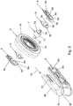
Fig. 5 eine Explosionsdarstellung; -
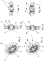
Fig. 6 bis 8 Darstellungen entsprechend denFig. 2 bis 4 der Laufrolle mit dem eingesteckten Achsstift; -
Fig. 9 bis 11 Darstellungen entsprechendFig. 2 bis 4 mit zusätzlich aufgesteckten Dämpfungsteilen; -
Fig. 12 bis 14 Darstellungen entsprechendFig. 2 bis 4 mit zusätzlich aufgesteckten Clipteilen; -
Fig. 15 bis 17 Darstellungen entsprechend denFig. 2 bis 4 , zusätzlich mit der Gabel, in der Position, in welcher die Clipteile in die Einschubbahnen der Gabel einschiebbar sind. - Ein Ausführungsbeispiel der Erfindung wird im Folgenden anhand der
Fig. 1 bis 17 erläutert. -
Fig. 1 zeigt einen Transportwagen 1, der mit in erfindungsgemäßer Weise aufgehängten Laufrollen 2 bestückt ist. Die Laufrollen 2 laufen auf von Schienen 3 gebildeten Laufbahnen ab. Die Ausrichtung der Laufrollen 2 gegenüber den Schienen 3 erfolgt mittels Führungsrollen 4, die mit seitlich an den Schienen 3 angeordneten Führungsflächen zusammenwirken, wie dies bekannt ist. - Die Laufrollen 2 sind mittels der Aufhängung mit Rahmenteilen 5 verbunden.
- Die Aufhängung für eine jeweilige Laufrolle 2 weist eine Gabel 6 auf, welche einen ersten und einen zweiten Gabelarm 6a, 6b besitzt, die durch einen Basisabschnitt 6c der Gabel miteinander verbunden sind.
- Die Laufrolle 2 ist durch einen in einer zentralen Öffnung 2a der Laufrolle 2 angeordneten Achsstift 7 im Zwischenraum zwischen den Gabelarmen 6a, 6b gehalten, wobei der Achsstift 7 in der im Weiteren beschriebenen Art und Weise mit den Gabelarmen 6a, 6b verbunden ist.
- Im Ausführungsbeispiel wird die Öffnung 2a vom Innenring eines Kugellagers 2b der Laufrolle ausgebildet, auf dessen Außenring die Felge 2c angeordnet ist, auf der außen wiederum der Laufbelag 2d angeordnet ist.
- Der Laufbelag 2d stellt eine Vollgummibereifung der Laufrolle 2 dar.
- Die Längsmittelachse des Achsstifts 7 stellt somit die Drehachse 10 dar, um welche die Laufrolle 2 drehbar ist.
- Der Achsstift 7 weist erste und zweite Endabschnitte 7a, 7b auf, welche in Ausnehmungen 8a von Clipteilen 8 ragen, wobei zwischen dem jeweiligen Endabschnitt 7a, 7b und dem jeweiligen Clipteil 8 ein jeweiliges Dämpfungsteil 9 liegt. Ein jeweiliges Dämpfungsteil 9 weist hierbei einen hülsenförmigen Abschnitt 9a auf, mit welchem es den jeweiligen Endabschnitt 7a des Achsstifts 7 umgibt und welcher in einem hülsenförmigen Abschnitt 8b des jeweiligen Clipteils aufgenommen ist.
- Der Achsstift 7b weist vorteilhafterweise einen mittleren Abschnitt 7c auf, der einen gegenüber den Endabschnitten 7a, 7b größeren Durchmesser aufweist und auf dem die Laufrolle (im Ausführungsbeispiel mit dem Innenring ihres Kugellagers 2b) angeordnet ist. An der jeweiligen Schulter 7d zwischen dem mittleren Abschnitt 7c und dem jeweiligen Endabschnitt 7a, 7b liegt ein Ringbund 9b des jeweiligen Dämpfungsteils 9 an. Der Ringbund 9b stellt einen scheibenförmigen Abschnitt des Dämpfungsteils 9 dar, welcher vom der Laufrolle 2 zugewandten Rand des hülsenförmigen Abschnitts 9a des Dämpfungsteils 9 nach außen absteht. Am der Laufrolle 2 zugewandten Ende des hülsenförmigen Abschnitts 8b des jeweiligen Clipteils 8 steht ebenfalls ein Ringbund 8c nach außen ab, der einen scheibenförmigen Abschnitt des Clipteils 8 bildet und an der von der Laufrolle 2 abgewandten Seite des Ringbunds 9b des Dämpfungsteils 9 anliegt. Ein jeweiliges Dämpfungsteil 9 wirkt damit nicht nur in radialer sondern auch in axialer Richtung.
- Die Gabelarme 6a, 6b der Gabel 6 weisen jeweils eine Einschubbahn 6d auf. Diese nimmt das jeweilige Clipteil 8 auf, wobei das Clipteil 8 durch eine Rastnase 8d, die in eine Rastausnehmung 6e der Gabel 6 eingreift, gegen eine Verschiebung in Längsrichtung der Einschubbahn 6d gesichert ist.
- Die an der der Laufrolle 2 zugewandten Innenseite des jeweiligen Gabelarms 6a, 6b angeordnete Einschubbahn 6d verläuft in Längsrichtung des jeweiligen Gabelarms. Ein jeweiliges Clipteil 8 ist durch einen Führungsabschnitt 8e, der an den hülsenförmigen Abschnitt 8b des Clipteils 8 anschließt, gegenüber der Einschubbahn 6d verschiebbar geführt.
- Der Führungsabschnitt 8e weist eine Längserstreckung auf, welche parallel zur Längserstreckung der Einschubbahn 6d liegt.
- Die Einschubbahn 6d wird von einer nutförmigen Vertiefung des Gabelarms 6a, 6b gebildet. Vorteilhafterweise kann diese nutförmige Vertiefung hinterschnittene Seitenwände aufweisen, sodass der Führungsabschnitt 8e gegen ein Herausfallen aus der Einschubbahn 6d in alle Richtungen rechtwinkelig zur Einschubrichtung 13 gesichert ist. Der Führungsabschnitt 8e greift hierzu in den hinterschnittenen Bereich der Einschubbahn 6d ein.
- Die Rastnase 8d ist am Führungsabschnitt 8e angeordnet und zwar in einem vom Verbindungsbereich des Führungsabschnitts 8e mit dem hülsenförmigen Abschnitt 8b abgelegenen Bereich.
- Die Dämpfungsteile 9 weisen im Ausführungsbeispiel Endkappen 9c auf, welche die hülsenförmigen Abschnitte 9a auf der gegenüberliegenden Seite des Ringbunds 9b verschließen.
- Zur Montage der Laufrolle 2 mit der die Laufrolle 2 drehbar lagernden Aufhängung wird zunächst der Achsstift 7 in die Öffnung 2a der Laufrolle 2 eingesteckt (in Richtung parallel zur Drehachse 10). Dieser Zustand ist in den
Fig. 6 bis 8 ersichtlich. - Im Weiteren werden die Dämpfungsteile 9 auf die Endabschnitte 7a, 7b des Achsstifts 7 aufgesteckt (in Richtung parallel zur Drehachse 10). Dieser Zustand ist in den
Fig. 9 bis 11 dargestellt. - Im Weiteren werden die Clipteile 8 auf die Dämpfungsteile 9 aufgesteckt (in Richtung parallel zur Drehachse 10). Die hülsenförmigen Abschnitte 8b der Clipteile 8 umgeben damit die hülsenförmigen Abschnitte 9a der Dämpfungsteile 9, welche wiederum den Achsstift 7 umgeben. Im Weiteren liegt der Ringbund 9b des jeweiligen Dämpfungsteils 9 an der jeweiligen Schulter 7d des Achsstifts 7 an und auf der gegenüberliegenden Seite liegt am Ringbund 9b des jeweiligen Dämpfungsteils 9 der Ringbund 8c des jeweiligen Clipteils 8 an. Dieser Zustand ist in den
Fig. 12 bis 14 dargestellt. - Die Laufrolle mit dem eingesteckten Achsstift 7 und den aufgesteckten Dämpfungsteilen 9 und Clipteilen 8 wird nunmehr vor dem Zwischenraum zwischen den Gabelarmen 6a, 6b positioniert, wie dies in den
Fig. 15 bis 17 dargestellt ist. Im Weiteren wird die Laufrolle in den Zwischenraum zwischen den Gabelarmen 6a, 6b eingeschoben, wobei die Clipteile 8 mit ihren Führungsabschnitten 8e in die Einschubrichtung 13 in die Einschubbahnen 6d eingeschoben werden, bis die Rastnasen 8d der Clipteile 8 in die Rastausnehmungen 6e der Gabelarme 6a, 6b einschnappen. Die Einschubrichtung 13 steht rechtwinkelig zur Drehachse 10. - Vorteilhafterweise liegt die Einschubrichtung 13 parallel zur Richtung der Längserstreckung (=Längsrichtung) der Gabelarme 6a, 6b. Die Einschubrichtung 13 steht damit rechtwinkelig zur Schwenkachse 11.
- Damit ist der in den
Fig. 2 bis 4 dargestellte Zustand erreicht. - Die Rastausnehmungen 6e sind im Ausführungsbeispiel in Form von Fensteröffnungen in den Gabelarmen 6a, 6b ausgebildet. Soll die Laufrolle 2 von der Aufhängung wieder demontiert werden, so können die Rastnasen 8d durch diese Fensteröffnungen hindurch eingedrückt werden, bis sie außer Eingriff der Rastausnehmungen 6e gelangen, worauf die Clipteile 8 entlang der Einschubbahnen 6d von den Gabelarmen 6a, 6b abgezogen werden können.
- Anstelle von Fensteröffnungen könnten die Rastausnehmungen 6e auch in Form von Vertiefungen ausgebildet sein, wobei dann zum außer Eingriff Bringen der Rastnasen 8d mit den Rastausnehmungen 6e die Führungsabschnitte 8e zusammengedrückt werden können.
- Die Gabel 6 ist im Ausführungsbeispiel um eine vertikale Schwenkachse 11 gegenüber dem Rahmenteil 5, an dem sie gehalten ist, verschwenkbar. Hierzu weist der Basisabschnitt 6c eine Durchgangsöffnung 6f auf, welche von einem Gelenkbolzen 12 durchsetzt ist, der am Rahmenteil 5 befestigt ist.
- Die Gabel 6 besteht vorzugsweise aus Kunststoff, beispielsweise PA. Der Kunststoff enthält günstigerweise Kohlefasern. Dadurch wird einer statischen Aufladung entgegengewirkt. Auch ein Gehalt von anderen elektrisch leitfähigen Fasern oder Partikeln und/oder eine elektrisch leitende Beschichtung könnte vorgesehen sein.
- Die Clipteile 8 bestehen vorzugsweise aus Kunststoff, beispielsweise PA. Der Kunststoff enthält günstigerweise Kohlefasern. Dadurch wird einer statischen Aufladung entgegengewirkt. Auch ein Gehalt von anderen elektrisch leitfähigen Fasern oder Partikeln und/oder eine elektrisch leitende Beschichtung könnte vorgesehen sein.
- Der Achsstift besteht vorzugsweise aus Kunststoff, beispielsweise PA. Der Kunststoff enthält günstigerweise Kohlefasern. Dadurch wird einer statischen Aufladung entgegengewirkt. Auch ein Gehalt von anderen elektrisch leitfähigen Fasern oder Partikeln und/oder eine elektrisch leitende Beschichtung könnte vorgesehen sein.
- Die Dämpfungsteile 9 bestehen vorzugsweise aus einem thermoplastischen Elastomer (TPE), beispielsweise PU. Eine Ausbildung aus einem anderen elastomeren Material ist ebenfalls denkbar und möglich.
- Durch die dem Achsstift und den Clipteilen 8 zwischengeschalteten Dämpfungsteile 9 wird ein ruhiger, vibrationsarmer Lauf erreicht. Grundsätzlich ist es auch denkbar und möglich, die Dämpfungsteile 9 wegzulassen. Die Clipteile 8 werden dann direkt auf die Endabschnitte 7a, 7b des Achsstifts 7 aufgesteckt und die Endabschnitte 7a, 7b des Achsstifts 7 werden direkt (und nicht unter Zwischenschaltung der Dämpfungsteile 9) von den Clipteilen 8 gehalten.
- Auch eine Ausbildung mit rechtwinkelig zur Längsrichtung der Gabelarme 6a, 6b sich erstreckenden Einschubbahnen, sodass also die Einschubrichtung 13 rechtwinkelig zur Richtung der Längserstreckung der Gabelarme 6a, 6b steht, ist denkbar und möglich.
- Durch die Erfindung können Kosten für die Herstellung und/oder Montage eingespart werden.
- Die erfindungsgemäße Einrichtung zeichnet sich auch durch ein geringes Gewicht aus.
- Wie beschrieben, kann die Erfindung insbesondere bei flurgebundenen, schienengeführten Transportwagen von Förderanlagen für Regallager für Stückgut eingesetzt werden. Aber auch ein Einsatz im Zusammenhang mit anderen Laufrollen, insbesondere solchen mit Vollgummibereifung, ist denkbar und möglich.
Legende zu den Hinweisziffern: 1 Transportwagen 9a hülsenförmiger Abschnitt 2 Laufrolle 9b Ringbund 2a Öffnung 9c Endkappe 2b Kugellager 10 Drehachse 2c Felge 11 Schwenkachse 2d Laufbelag 12 Gelenkbolzen 3 Schiene 13 Einschubrichtung 4 Führungsrolle 5 Rahmenteil 6 Gabel 6a Gabelarm 6b Gabelarm 6c Basisabschnitt 6d Einschubbahn 6e Rastausnehmung 6f Durchgangsöffnung 7 Achsstift 7a Endabschnitt 7b Endabschnitt 7c mittlerer Abschnitt 7d Schulter 8 Clipteil 8a Ausnehmung 8b hülsenförmiger Abschnitt 8c Ringbund 8d Rastnase 8e Führungsabschnitt 9 Dämpfungsteil
Claims (10)
- Einrichtung umfassend eine um eine Drehachse (10) drehbare Laufrolle (2) für eine Förderanlage und eine die Laufrolle (2) tragende Aufhängung, welche eine Gabel (6) und einen Achsstift (7) aufweist, der die Laufrolle (2) durchsetzt und von der Gabel (6) getragen ist, dadurch gekennzeichnet, dass die Aufhängung im Weiteren ein erstes und ein zweites Clipteil (8) aufweist, welche jeweils eine Ausnehmung (8a) aufweisen, in die ein jeweiliger Endabschnitt (7a, 7b) des Achsstifts (7) ragt und welche zum Verbinden mit der Gabel (6) jeweils in eine rechtwinkelig zur Drehachse (10) liegende Einschubrichtung (13) in eine jeweilige Einschubbahn (6d) der Gabel (6) einschiebbar und mit der Gabel (6) zusammenschnappbar sind.
- Einrichtung nach Anspruch 1, dadurch gekennzeichnet, dass die Einschubbahnen (6d) an den der Laufrolle (2) zugewandten Innenseiten von beidseitig der Laufrolle (2) liegenden Gabelarmen (6a, 6b) der Gabel (6) angeordnet sind.
- Einrichtung nach Anspruch 1 oder 2, dadurch gekennzeichnet, dass die Einschubbahnen (6d) in Längsrichtung der Gabelarme (6a, 6b) verlaufen.
- Einrichtung nach einem der Ansprüche 1 bis 3, dadurch gekennzeichnet, dass die Gabelarme (6a, 6b) durch einen Basisabschnitt (6c) miteinander verbunden sind, der eine Durchgangsöffnung (6f) zum Durchtritt eines Gelenkbolzens (12) aufweist.
- Einrichtung nach einem der Ansprüche 1 bis 4, dadurch gekennzeichnet, dass zwischen dem jeweiligen Clipteil (8) und dem jeweiligen Endabschnitt (7a, 7b) des Achsstifts (7) jeweils ein Dämpfungsteil (9) angeordnet ist.
- Einrichtung nach Anspruch 5, dadurch gekennzeichnet, dass ein hülsenförmiger Abschnitt (9a) des Dämpfungsteils (9) den Achsstift (7) umgibt und von einem hülsenförmigen Abschnitt (8b) des Clipteils (8) umgeben wird.
- Einrichtung nach einem der Ansprüche 1 bis 6, dadurch gekennzeichnet, dass die Endabschnitte (7a, 7b) des Achsstifts (7) einen kleineren Durchmesser als ein mittlerer Abschnitt (7c) des Achsstifts (7) aufweisen und ein vom hülsenförmigen Abschnitt (9a) des jeweiligen Dämpfungsteils (9) abstehender Ringbund (9b) des Dämpfungsteils (9) an der jeweiligen Schulter (7d) zwischen dem mittleren Abschnitt (7c) und dem jeweiligen Endabschnitt (7a, 7b) des Achsstifts (7) anliegt.
- Einrichtung nach Anspruch 6 oder nach Anspruch 7, wenn abhängig von Anspruch 6, dadurch gekennzeichnet, dass an den hülsenförmigen Abschnitt (8b) eines jeweiligen Clipteils (8) ein Führungsabschnitt (8e) anschließt, der von der jeweiligen Einschubbahn (6d) der Gabel (6) verschiebbar geführt ist.
- Einrichtung nach einem der Ansprüche 1 bis 8, dadurch gekennzeichnet, dass die Gabel (6) und die Clipteile (8) aus Kunststoff bestehen.
- Einrichtung nach einem der Ansprüche 1 bis 9, dadurch gekennzeichnet, dass der Achsstift (7) aus Kunststoff besteht.
Applications Claiming Priority (1)
| Application Number | Priority Date | Filing Date | Title |
|---|---|---|---|
| ATA199/2018A AT520732B1 (de) | 2018-07-05 | 2018-07-05 | Einrichtung umfassend eine Laufrolle und eine die Laufrolle tragende Aufhängung |
Publications (2)
| Publication Number | Publication Date |
|---|---|
| EP3594017A1 EP3594017A1 (de) | 2020-01-15 |
| EP3594017B1 true EP3594017B1 (de) | 2020-08-26 |
Family
ID=66751953
Family Applications (1)
| Application Number | Title | Priority Date | Filing Date |
|---|---|---|---|
| EP19178024.6A Not-in-force EP3594017B1 (de) | 2018-07-05 | 2019-06-04 | Einrichtung umfassend eine laufrolle und eine die laufrolle tragende aufhängung |
Country Status (6)
| Country | Link |
|---|---|
| US (1) | US10829133B2 (de) |
| EP (1) | EP3594017B1 (de) |
| CN (1) | CN110683261B (de) |
| AT (1) | AT520732B1 (de) |
| CA (1) | CA3047572A1 (de) |
| ES (1) | ES2831110T3 (de) |
Families Citing this family (4)
| Publication number | Priority date | Publication date | Assignee | Title |
|---|---|---|---|---|
| CN110877623A (zh) * | 2019-11-27 | 2020-03-13 | 中车山东机车车辆有限公司 | 一种轴端连接装置、轮对组成及铁路车辆 |
| CN112089267B (zh) * | 2020-08-31 | 2025-10-21 | 思创医惠科技股份有限公司 | 一种智能货架推进器装置 |
| AT524624B1 (de) * | 2020-12-21 | 2023-09-15 | Faigle Kunststoffe Gmbh | Fahrwerk für ein schienengebundenes Transportfahrzeug |
| AT527639A1 (de) | 2023-09-28 | 2025-04-15 | Faigle Kunststoffe Gmbh | Laufrollenanordnung |
Family Cites Families (40)
| Publication number | Priority date | Publication date | Assignee | Title |
|---|---|---|---|---|
| CH649048A5 (en) * | 1980-10-02 | 1985-04-30 | Wanzl Kg Rudolf | Support castor for manually moved trolleys, in particular shopping trolleys |
| US5355664A (en) * | 1992-12-21 | 1994-10-18 | The Toro Company | Caster wheel suspension and shaft tensioning system for turf maintenance equipment |
| US5448796A (en) * | 1993-10-20 | 1995-09-12 | Larson; Albert W. | Sprung castor wheel assembly |
| US5967535A (en) * | 1997-08-14 | 1999-10-19 | Graco Children's Products Inc. | Swivel wheel mount |
| US5950279A (en) * | 1997-10-29 | 1999-09-14 | Reflectolite Products Company, Inc. | Modular sliding door rollers |
| US6357077B1 (en) * | 1999-10-15 | 2002-03-19 | Hamilton Caster & Mfg. Co. | Spring loaded caster |
| DE10106158B4 (de) * | 2001-02-10 | 2013-12-24 | Bayerische Motoren Werke Aktiengesellschaft | Spannvorrichtung für ein Gabelstück |
| DE20108132U1 (de) * | 2001-05-14 | 2002-09-26 | Mödlhammer, Raimund, 50678 Köln | Radfederung |
| US6499184B2 (en) * | 2001-05-14 | 2002-12-31 | Ross Design & Engineering, Inc. | Elastomeric biased caster |
| CN2530825Y (zh) * | 2002-01-22 | 2003-01-15 | 朱惠雄 | 改进的双刹车脚轮 |
| US7093319B2 (en) * | 2002-06-28 | 2006-08-22 | Superior Tire & Rubber Corporation | Industrial caster wheel with elastomeric spring/damper member and adjustment member |
| US20040068831A1 (en) * | 2002-07-06 | 2004-04-15 | Caruso Jerome C. | Caster construction |
| JP2004042685A (ja) * | 2002-07-08 | 2004-02-12 | Youth Engineering Co Ltd | キャスター |
| US6823560B2 (en) * | 2002-10-02 | 2004-11-30 | Ching-Sung Lin | Buffering structure for wheels |
| US6748623B1 (en) * | 2002-11-27 | 2004-06-15 | Po-Chuan Tsai | Chair caster |
| US6880833B2 (en) * | 2003-01-28 | 2005-04-19 | Manuel Polanco | Modular roller skate apparatus |
| CN100498670C (zh) * | 2007-06-06 | 2009-06-10 | 张家港森安尊金属制品有限公司 | 一种鼠标腕垫 |
| WO2008137847A1 (en) * | 2007-05-07 | 2008-11-13 | Jacob Holtz Company | Caster with weight transferring tab |
| US7849560B2 (en) * | 2007-07-18 | 2010-12-14 | Kelley Traci L | Self-adjusting window roller apparatus and method of use |
| US8210550B2 (en) * | 2008-06-09 | 2012-07-03 | Orbit Baby, Inc. | Suspension system for baby stroller |
| US8413295B2 (en) * | 2008-08-27 | 2013-04-09 | Glenn Campbell | Caster wheel system |
| AT11034U1 (de) * | 2009-01-16 | 2010-03-15 | Faigle Kunststoffe Gmbh | Reibrad mit einem radkörper |
| KR101105270B1 (ko) * | 2009-12-22 | 2012-01-17 | 금성에이스산업(주) | 이송롤러 유닛 및 이를 이용한 이송장치 |
| US8141331B2 (en) * | 2010-04-20 | 2012-03-27 | Cnh America Llc | Divider support apparatus with integral adjustable torsional preload mechanism and vibration damper |
| TWM403442U (en) * | 2010-12-09 | 2011-05-11 | Haion Caster Ind Co Ltd | Assembly structure of caster casing |
| US8807580B2 (en) * | 2011-09-07 | 2014-08-19 | Cnh Industrial America Llc | Axle assembly for agricultural applicator |
| US8628098B2 (en) * | 2011-09-07 | 2014-01-14 | Cnh America Llc | Fork assembly for agricultural applicator |
| US20140041433A1 (en) * | 2012-08-09 | 2014-02-13 | Ingersoll CM Systems | Rolling tool assemblies for crankshaft rolling machines |
| US8955195B2 (en) * | 2012-11-25 | 2015-02-17 | Door & Window Hardware Co. | Clamping-sliding assembly for a single-track-suspension sliding door |
| TWM459132U (zh) * | 2012-12-28 | 2013-08-11 | Kun-Chi Jiang | 定位腳輪 |
| EP3071007B1 (de) * | 2013-11-11 | 2018-06-06 | Fuji Machine Mfg. Co., Ltd. | Komponentenmontagevorrichtung |
| WO2015121786A2 (en) * | 2014-02-12 | 2015-08-20 | Avancon Sa | Transferring assembly for conveying systems |
| DE102014002610B3 (de) * | 2014-02-27 | 2015-05-28 | Steinco Paul Vom Stein Gmbh | Einradrolle |
| CN203957720U (zh) * | 2014-07-23 | 2014-11-26 | 温州市瓯海丽岙跃进橡塑复合厂 | 一种滚轮组件 |
| DE102015003425A1 (de) * | 2015-03-17 | 2016-09-22 | Günther Zimmer | Schiebetür mit türmassenunabhängigem Türbeschlag |
| US10052910B2 (en) * | 2015-11-10 | 2018-08-21 | Uremet Corporation | Illuminated system for use with amusement rides |
| WO2017214101A1 (en) * | 2016-06-08 | 2017-12-14 | Rexnord Industries, Llc | Drive assembly for a modular conveyor |
| CN206842382U (zh) * | 2017-05-05 | 2018-01-05 | 湖州哥伦布物流科技有限公司 | 仓库中行走设施的导向系统及带有该导向系统的搬运系统 |
| CN206826326U (zh) * | 2017-06-07 | 2018-01-02 | 温州理念箱包配件有限公司 | 减震式脚轮组件 |
| CN207000047U (zh) * | 2017-06-14 | 2018-02-13 | 安徽江淮汽车集团股份有限公司 | 驻车轮 |
-
2018
- 2018-07-05 AT ATA199/2018A patent/AT520732B1/de not_active IP Right Cessation
-
2019
- 2019-06-04 ES ES19178024T patent/ES2831110T3/es active Active
- 2019-06-04 EP EP19178024.6A patent/EP3594017B1/de not_active Not-in-force
- 2019-06-20 CA CA3047572A patent/CA3047572A1/en active Pending
- 2019-06-25 US US16/451,634 patent/US10829133B2/en active Active
- 2019-07-05 CN CN201910604564.9A patent/CN110683261B/zh active Active
Non-Patent Citations (1)
| Title |
|---|
| None * |
Also Published As
| Publication number | Publication date |
|---|---|
| CN110683261A (zh) | 2020-01-14 |
| AT520732B1 (de) | 2019-07-15 |
| ES2831110T3 (es) | 2021-06-07 |
| AT520732A4 (de) | 2019-07-15 |
| CA3047572A1 (en) | 2020-01-05 |
| EP3594017A1 (de) | 2020-01-15 |
| CN110683261B (zh) | 2022-09-27 |
| US10829133B2 (en) | 2020-11-10 |
| US20200010099A1 (en) | 2020-01-09 |
Similar Documents
| Publication | Publication Date | Title |
|---|---|---|
| EP3594017B1 (de) | Einrichtung umfassend eine laufrolle und eine die laufrolle tragende aufhängung | |
| EP3496971B1 (de) | Schienensystem für einen fahrzeugsitz | |
| DE102008019976A1 (de) | Omnidirektional-Rad und Verfahren zur Montage von Rollkörpern eines Omnidirektional-Rades, sowie omnidirektional bewegliches Fahrwerk und dessen Verwendung | |
| WO1996022205A1 (de) | Wischblatt | |
| EP2619124B1 (de) | Stromabnehmerwagen mit lösbar befestigten fahrwerken | |
| EP2576244A1 (de) | Elektrischer radantrieb | |
| DE4432129C1 (de) | Radmontage-Bauteilgruppe für einen Handwagen | |
| DE102022002435A1 (de) | Mobiles Transportsystem | |
| WO2013189846A1 (de) | Lagervorrichtung mit wenigstens einem achsschenkelbolzen | |
| WO2012107338A2 (de) | Stromabnehmerwagen mit lösbar befestigten fahrwerken | |
| EP2530344B1 (de) | Rollelement eines Tripodegelenks sowie Tripodegelenk, aufweisend ein derartiges Rollelement | |
| DE202020100802U1 (de) | Stromabnehmeranordnung, Stromabnehmer und stromleitende Schiene zur Verwendung darin | |
| WO1981002999A1 (en) | Wheel suspension | |
| DE102014206384B4 (de) | Rollenwagen | |
| DE202017100498U1 (de) | Lenkrolle für insbesondere Transportgeräte | |
| DE102011083885B4 (de) | Radanordnung für eine Bodendüse eines Staubsaugers | |
| EP2894361B1 (de) | Tripodgelenk mit segmentierten Rollkörpern | |
| DE3220388A1 (de) | Lenkrolle fuer moebel, apparate u. dgl. objekte | |
| DE102017211393A1 (de) | Anordnung zur Verbindung eines Fahrwerkslenkers mit einem Radträger | |
| DE202020100166U1 (de) | Befestigungsanordnung mit einem ersten Befestigungsabschnitt, insbesondere für eine mobile Einrichtung | |
| DE2121234A1 (de) | Platten Forderband | |
| DE10307532A1 (de) | Anordnung zum Anschluß einer Vakuumleitung an eine Kraftfahrzeugkomponente | |
| DE7917154U1 (de) | Laufrad fuer transportwagen u.dgl. | |
| DE102015102248B3 (de) | Positionierclip aus Kunststoff | |
| DE3148916A1 (de) | Laufrolle fuer insbesondere apparate, transportgeraete od. dgl. |
Legal Events
| Date | Code | Title | Description |
|---|---|---|---|
| PUAI | Public reference made under article 153(3) epc to a published international application that has entered the european phase |
Free format text: ORIGINAL CODE: 0009012 |
|
| STAA | Information on the status of an ep patent application or granted ep patent |
Free format text: STATUS: THE APPLICATION HAS BEEN PUBLISHED |
|
| AK | Designated contracting states |
Kind code of ref document: A1 Designated state(s): AL AT BE BG CH CY CZ DE DK EE ES FI FR GB GR HR HU IE IS IT LI LT LU LV MC MK MT NL NO PL PT RO RS SE SI SK SM TR |
|
| AX | Request for extension of the european patent |
Extension state: BA ME |
|
| STAA | Information on the status of an ep patent application or granted ep patent |
Free format text: STATUS: REQUEST FOR EXAMINATION WAS MADE |
|
| 17P | Request for examination filed |
Effective date: 20200304 |
|
| RBV | Designated contracting states (corrected) |
Designated state(s): AL AT BE BG CH CY CZ DE DK EE ES FI FR GB GR HR HU IE IS IT LI LT LU LV MC MK MT NL NO PL PT RO RS SE SI SK SM TR |
|
| GRAP | Despatch of communication of intention to grant a patent |
Free format text: ORIGINAL CODE: EPIDOSNIGR1 |
|
| STAA | Information on the status of an ep patent application or granted ep patent |
Free format text: STATUS: GRANT OF PATENT IS INTENDED |
|
| RIC1 | Information provided on ipc code assigned before grant |
Ipc: B65G 39/02 20060101ALI20200428BHEP Ipc: B60B 33/00 20060101AFI20200428BHEP |
|
| INTG | Intention to grant announced |
Effective date: 20200520 |
|
| GRAS | Grant fee paid |
Free format text: ORIGINAL CODE: EPIDOSNIGR3 |
|
| GRAA | (expected) grant |
Free format text: ORIGINAL CODE: 0009210 |
|
| STAA | Information on the status of an ep patent application or granted ep patent |
Free format text: STATUS: THE PATENT HAS BEEN GRANTED |
|
| AK | Designated contracting states |
Kind code of ref document: B1 Designated state(s): AL AT BE BG CH CY CZ DE DK EE ES FI FR GB GR HR HU IE IS IT LI LT LU LV MC MK MT NL NO PL PT RO RS SE SI SK SM TR |
|
| REG | Reference to a national code |
Ref country code: GB Ref legal event code: FG4D Free format text: NOT ENGLISH |
|
| REG | Reference to a national code |
Ref country code: CH Ref legal event code: EP |
|
| REG | Reference to a national code |
Ref country code: AT Ref legal event code: REF Ref document number: 1306022 Country of ref document: AT Kind code of ref document: T Effective date: 20200915 |
|
| REG | Reference to a national code |
Ref country code: IE Ref legal event code: FG4D Free format text: LANGUAGE OF EP DOCUMENT: GERMAN |
|
| REG | Reference to a national code |
Ref country code: DE Ref legal event code: R096 Ref document number: 502019000174 Country of ref document: DE |
|
| REG | Reference to a national code |
Ref country code: NL Ref legal event code: FP |
|
| REG | Reference to a national code |
Ref country code: LT Ref legal event code: MG4D |
|
| PG25 | Lapsed in a contracting state [announced via postgrant information from national office to epo] |
Ref country code: FI Free format text: LAPSE BECAUSE OF FAILURE TO SUBMIT A TRANSLATION OF THE DESCRIPTION OR TO PAY THE FEE WITHIN THE PRESCRIBED TIME-LIMIT Effective date: 20200826 Ref country code: NO Free format text: LAPSE BECAUSE OF FAILURE TO SUBMIT A TRANSLATION OF THE DESCRIPTION OR TO PAY THE FEE WITHIN THE PRESCRIBED TIME-LIMIT Effective date: 20201126 Ref country code: GR Free format text: LAPSE BECAUSE OF FAILURE TO SUBMIT A TRANSLATION OF THE DESCRIPTION OR TO PAY THE FEE WITHIN THE PRESCRIBED TIME-LIMIT Effective date: 20201127 Ref country code: PT Free format text: LAPSE BECAUSE OF FAILURE TO SUBMIT A TRANSLATION OF THE DESCRIPTION OR TO PAY THE FEE WITHIN THE PRESCRIBED TIME-LIMIT Effective date: 20201228 Ref country code: SE Free format text: LAPSE BECAUSE OF FAILURE TO SUBMIT A TRANSLATION OF THE DESCRIPTION OR TO PAY THE FEE WITHIN THE PRESCRIBED TIME-LIMIT Effective date: 20200826 Ref country code: BG Free format text: LAPSE BECAUSE OF FAILURE TO SUBMIT A TRANSLATION OF THE DESCRIPTION OR TO PAY THE FEE WITHIN THE PRESCRIBED TIME-LIMIT Effective date: 20201126 Ref country code: HR Free format text: LAPSE BECAUSE OF FAILURE TO SUBMIT A TRANSLATION OF THE DESCRIPTION OR TO PAY THE FEE WITHIN THE PRESCRIBED TIME-LIMIT Effective date: 20200826 Ref country code: LT Free format text: LAPSE BECAUSE OF FAILURE TO SUBMIT A TRANSLATION OF THE DESCRIPTION OR TO PAY THE FEE WITHIN THE PRESCRIBED TIME-LIMIT Effective date: 20200826 |
|
| PG25 | Lapsed in a contracting state [announced via postgrant information from national office to epo] |
Ref country code: LV Free format text: LAPSE BECAUSE OF FAILURE TO SUBMIT A TRANSLATION OF THE DESCRIPTION OR TO PAY THE FEE WITHIN THE PRESCRIBED TIME-LIMIT Effective date: 20200826 Ref country code: PL Free format text: LAPSE BECAUSE OF FAILURE TO SUBMIT A TRANSLATION OF THE DESCRIPTION OR TO PAY THE FEE WITHIN THE PRESCRIBED TIME-LIMIT Effective date: 20200826 Ref country code: RS Free format text: LAPSE BECAUSE OF FAILURE TO SUBMIT A TRANSLATION OF THE DESCRIPTION OR TO PAY THE FEE WITHIN THE PRESCRIBED TIME-LIMIT Effective date: 20200826 Ref country code: IS Free format text: LAPSE BECAUSE OF FAILURE TO SUBMIT A TRANSLATION OF THE DESCRIPTION OR TO PAY THE FEE WITHIN THE PRESCRIBED TIME-LIMIT Effective date: 20201226 |
|
| PG25 | Lapsed in a contracting state [announced via postgrant information from national office to epo] |
Ref country code: SM Free format text: LAPSE BECAUSE OF FAILURE TO SUBMIT A TRANSLATION OF THE DESCRIPTION OR TO PAY THE FEE WITHIN THE PRESCRIBED TIME-LIMIT Effective date: 20200826 Ref country code: EE Free format text: LAPSE BECAUSE OF FAILURE TO SUBMIT A TRANSLATION OF THE DESCRIPTION OR TO PAY THE FEE WITHIN THE PRESCRIBED TIME-LIMIT Effective date: 20200826 Ref country code: RO Free format text: LAPSE BECAUSE OF FAILURE TO SUBMIT A TRANSLATION OF THE DESCRIPTION OR TO PAY THE FEE WITHIN THE PRESCRIBED TIME-LIMIT Effective date: 20200826 Ref country code: DK Free format text: LAPSE BECAUSE OF FAILURE TO SUBMIT A TRANSLATION OF THE DESCRIPTION OR TO PAY THE FEE WITHIN THE PRESCRIBED TIME-LIMIT Effective date: 20200826 Ref country code: CZ Free format text: LAPSE BECAUSE OF FAILURE TO SUBMIT A TRANSLATION OF THE DESCRIPTION OR TO PAY THE FEE WITHIN THE PRESCRIBED TIME-LIMIT Effective date: 20200826 |
|
| REG | Reference to a national code |
Ref country code: DE Ref legal event code: R097 Ref document number: 502019000174 Country of ref document: DE |
|
| PG25 | Lapsed in a contracting state [announced via postgrant information from national office to epo] |
Ref country code: AL Free format text: LAPSE BECAUSE OF FAILURE TO SUBMIT A TRANSLATION OF THE DESCRIPTION OR TO PAY THE FEE WITHIN THE PRESCRIBED TIME-LIMIT Effective date: 20200826 |
|
| REG | Reference to a national code |
Ref country code: ES Ref legal event code: FG2A Ref document number: 2831110 Country of ref document: ES Kind code of ref document: T3 Effective date: 20210607 |
|
| PG25 | Lapsed in a contracting state [announced via postgrant information from national office to epo] |
Ref country code: SK Free format text: LAPSE BECAUSE OF FAILURE TO SUBMIT A TRANSLATION OF THE DESCRIPTION OR TO PAY THE FEE WITHIN THE PRESCRIBED TIME-LIMIT Effective date: 20200826 |
|
| PLBE | No opposition filed within time limit |
Free format text: ORIGINAL CODE: 0009261 |
|
| STAA | Information on the status of an ep patent application or granted ep patent |
Free format text: STATUS: NO OPPOSITION FILED WITHIN TIME LIMIT |
|
| 26N | No opposition filed |
Effective date: 20210527 |
|
| PG25 | Lapsed in a contracting state [announced via postgrant information from national office to epo] |
Ref country code: MC Free format text: LAPSE BECAUSE OF FAILURE TO SUBMIT A TRANSLATION OF THE DESCRIPTION OR TO PAY THE FEE WITHIN THE PRESCRIBED TIME-LIMIT Effective date: 20200826 |
|
| REG | Reference to a national code |
Ref country code: BE Ref legal event code: MM Effective date: 20210630 |
|
| PG25 | Lapsed in a contracting state [announced via postgrant information from national office to epo] |
Ref country code: LU Free format text: LAPSE BECAUSE OF NON-PAYMENT OF DUE FEES Effective date: 20210604 |
|
| PG25 | Lapsed in a contracting state [announced via postgrant information from national office to epo] |
Ref country code: IE Free format text: LAPSE BECAUSE OF NON-PAYMENT OF DUE FEES Effective date: 20210604 |
|
| PG25 | Lapsed in a contracting state [announced via postgrant information from national office to epo] |
Ref country code: BE Free format text: LAPSE BECAUSE OF NON-PAYMENT OF DUE FEES Effective date: 20210630 |
|
| REG | Reference to a national code |
Ref country code: CH Ref legal event code: PL |
|
| PG25 | Lapsed in a contracting state [announced via postgrant information from national office to epo] |
Ref country code: LI Free format text: LAPSE BECAUSE OF NON-PAYMENT OF DUE FEES Effective date: 20220630 Ref country code: CH Free format text: LAPSE BECAUSE OF NON-PAYMENT OF DUE FEES Effective date: 20220630 |
|
| P01 | Opt-out of the competence of the unified patent court (upc) registered |
Effective date: 20230512 |
|
| PG25 | Lapsed in a contracting state [announced via postgrant information from national office to epo] |
Ref country code: CY Free format text: LAPSE BECAUSE OF FAILURE TO SUBMIT A TRANSLATION OF THE DESCRIPTION OR TO PAY THE FEE WITHIN THE PRESCRIBED TIME-LIMIT Effective date: 20200826 |
|
| PG25 | Lapsed in a contracting state [announced via postgrant information from national office to epo] |
Ref country code: HU Free format text: LAPSE BECAUSE OF FAILURE TO SUBMIT A TRANSLATION OF THE DESCRIPTION OR TO PAY THE FEE WITHIN THE PRESCRIBED TIME-LIMIT; INVALID AB INITIO Effective date: 20190604 |
|
| PGFP | Annual fee paid to national office [announced via postgrant information from national office to epo] |
Ref country code: NL Payment date: 20230626 Year of fee payment: 5 Ref country code: FR Payment date: 20230622 Year of fee payment: 5 Ref country code: DE Payment date: 20230627 Year of fee payment: 5 |
|
| PG25 | Lapsed in a contracting state [announced via postgrant information from national office to epo] |
Ref country code: SI Free format text: LAPSE BECAUSE OF FAILURE TO SUBMIT A TRANSLATION OF THE DESCRIPTION OR TO PAY THE FEE WITHIN THE PRESCRIBED TIME-LIMIT Effective date: 20200826 |
|
| PGFP | Annual fee paid to national office [announced via postgrant information from national office to epo] |
Ref country code: IT Payment date: 20230620 Year of fee payment: 5 Ref country code: GB Payment date: 20230620 Year of fee payment: 5 Ref country code: ES Payment date: 20230721 Year of fee payment: 5 |
|
| PG25 | Lapsed in a contracting state [announced via postgrant information from national office to epo] |
Ref country code: MK Free format text: LAPSE BECAUSE OF FAILURE TO SUBMIT A TRANSLATION OF THE DESCRIPTION OR TO PAY THE FEE WITHIN THE PRESCRIBED TIME-LIMIT Effective date: 20200826 |
|
| PG25 | Lapsed in a contracting state [announced via postgrant information from national office to epo] |
Ref country code: MT Free format text: LAPSE BECAUSE OF FAILURE TO SUBMIT A TRANSLATION OF THE DESCRIPTION OR TO PAY THE FEE WITHIN THE PRESCRIBED TIME-LIMIT Effective date: 20200826 |
|
| REG | Reference to a national code |
Ref country code: DE Ref legal event code: R119 Ref document number: 502019000174 Country of ref document: DE |
|
| REG | Reference to a national code |
Ref country code: NL Ref legal event code: MM Effective date: 20240701 |
|
| GBPC | Gb: european patent ceased through non-payment of renewal fee |
Effective date: 20240604 |
|
| PG25 | Lapsed in a contracting state [announced via postgrant information from national office to epo] |
Ref country code: NL Free format text: LAPSE BECAUSE OF NON-PAYMENT OF DUE FEES Effective date: 20240701 |
|
| PG25 | Lapsed in a contracting state [announced via postgrant information from national office to epo] |
Ref country code: NL Free format text: LAPSE BECAUSE OF NON-PAYMENT OF DUE FEES Effective date: 20240701 |
|
| PG25 | Lapsed in a contracting state [announced via postgrant information from national office to epo] |
Ref country code: DE Free format text: LAPSE BECAUSE OF NON-PAYMENT OF DUE FEES Effective date: 20250101 |
|
| PG25 | Lapsed in a contracting state [announced via postgrant information from national office to epo] |
Ref country code: FR Free format text: LAPSE BECAUSE OF NON-PAYMENT OF DUE FEES Effective date: 20240630 |
|
| PG25 | Lapsed in a contracting state [announced via postgrant information from national office to epo] |
Ref country code: IT Free format text: LAPSE BECAUSE OF NON-PAYMENT OF DUE FEES Effective date: 20240604 Ref country code: GB Free format text: LAPSE BECAUSE OF NON-PAYMENT OF DUE FEES Effective date: 20240604 |
|
| REG | Reference to a national code |
Ref country code: ES Ref legal event code: FD2A Effective date: 20250728 |
|
| REG | Reference to a national code |
Ref country code: AT Ref legal event code: MM01 Ref document number: 1306022 Country of ref document: AT Kind code of ref document: T Effective date: 20240604 |
|
| PG25 | Lapsed in a contracting state [announced via postgrant information from national office to epo] |
Ref country code: ES Free format text: LAPSE BECAUSE OF NON-PAYMENT OF DUE FEES Effective date: 20240605 |
|
| PG25 | Lapsed in a contracting state [announced via postgrant information from national office to epo] |
Ref country code: AT Free format text: LAPSE BECAUSE OF NON-PAYMENT OF DUE FEES Effective date: 20240604 |
|
| PG25 | Lapsed in a contracting state [announced via postgrant information from national office to epo] |
Ref country code: TR Free format text: LAPSE BECAUSE OF FAILURE TO SUBMIT A TRANSLATION OF THE DESCRIPTION OR TO PAY THE FEE WITHIN THE PRESCRIBED TIME-LIMIT Effective date: 20200826 |
|
| PGFP | Annual fee paid to national office [announced via postgrant information from national office to epo] |
Ref country code: AT Payment date: 20260410 Year of fee payment: 5 |