EP3593924B1 - Vorrichtung mit filtermodul zur herstellung von druckgussteilen - Google Patents
Vorrichtung mit filtermodul zur herstellung von druckgussteilen Download PDFInfo
- Publication number
- EP3593924B1 EP3593924B1 EP19186006.3A EP19186006A EP3593924B1 EP 3593924 B1 EP3593924 B1 EP 3593924B1 EP 19186006 A EP19186006 A EP 19186006A EP 3593924 B1 EP3593924 B1 EP 3593924B1
- Authority
- EP
- European Patent Office
- Prior art keywords
- filter
- filter module
- mold
- valve
- vacuum
- Prior art date
- Legal status (The legal status is an assumption and is not a legal conclusion. Google has not performed a legal analysis and makes no representation as to the accuracy of the status listed.)
- Active
Links
Images

Classifications
-
- B—PERFORMING OPERATIONS; TRANSPORTING
- B22—CASTING; POWDER METALLURGY
- B22D—CASTING OF METALS; CASTING OF OTHER SUBSTANCES BY THE SAME PROCESSES OR DEVICES
- B22D17/00—Pressure die casting or injection die casting, i.e. casting in which the metal is forced into a mould under high pressure
- B22D17/14—Machines with evacuated die cavity
- B22D17/145—Venting means therefor
-
- B—PERFORMING OPERATIONS; TRANSPORTING
- B01—PHYSICAL OR CHEMICAL PROCESSES OR APPARATUS IN GENERAL
- B01D—SEPARATION
- B01D46/00—Filters or filtering processes specially modified for separating dispersed particles from gases or vapours
- B01D46/10—Particle separators, e.g. dust precipitators, using filter plates, sheets or pads having plane surfaces
- B01D46/12—Particle separators, e.g. dust precipitators, using filter plates, sheets or pads having plane surfaces in multiple arrangements
-
- B—PERFORMING OPERATIONS; TRANSPORTING
- B22—CASTING; POWDER METALLURGY
- B22D—CASTING OF METALS; CASTING OF OTHER SUBSTANCES BY THE SAME PROCESSES OR DEVICES
- B22D17/00—Pressure die casting or injection die casting, i.e. casting in which the metal is forced into a mould under high pressure
- B22D17/14—Machines with evacuated die cavity
-
- B—PERFORMING OPERATIONS; TRANSPORTING
- B22—CASTING; POWDER METALLURGY
- B22D—CASTING OF METALS; CASTING OF OTHER SUBSTANCES BY THE SAME PROCESSES OR DEVICES
- B22D17/00—Pressure die casting or injection die casting, i.e. casting in which the metal is forced into a mould under high pressure
- B22D17/20—Accessories: Details
-
- B—PERFORMING OPERATIONS; TRANSPORTING
- B22—CASTING; POWDER METALLURGY
- B22D—CASTING OF METALS; CASTING OF OTHER SUBSTANCES BY THE SAME PROCESSES OR DEVICES
- B22D17/00—Pressure die casting or injection die casting, i.e. casting in which the metal is forced into a mould under high pressure
- B22D17/20—Accessories: Details
- B22D17/22—Dies; Die plates; Die supports; Cooling equipment for dies; Accessories for loosening and ejecting castings from dies
-
- B—PERFORMING OPERATIONS; TRANSPORTING
- B22—CASTING; POWDER METALLURGY
- B22D—CASTING OF METALS; CASTING OF OTHER SUBSTANCES BY THE SAME PROCESSES OR DEVICES
- B22D17/00—Pressure die casting or injection die casting, i.e. casting in which the metal is forced into a mould under high pressure
- B22D17/20—Accessories: Details
- B22D17/32—Controlling equipment
Definitions
- the present invention relates to a device with a filter module for producing die-cast parts with a die-casting mold and a suction device provided for the controlled evacuation of a mold cavity, which consists of a vacuum unit and a suction line connecting the vacuum unit and the die-casting mold.
- a generic device for producing die-cast parts is from the DE 30 02 886 C2 known.
- the final mold is filled with liquid metal in conjunction with the evacuation of the mold within a few milliseconds.
- the aim is to achieve the highest possible vacuum in the mold cavity of the casting mold in order to achieve the highest possible quality of the casting.
- the EP 0 600 324 A1 describes a method for producing a vacuum in a vacuum die casting machine, in which the vacuum to be applied to the die casting mold can be subjected to regulation during the casting process.
- the pressure curve of the vacuum applied via a vacuum valve is regulated by means of a switching valve in such a way that the pressure in the mold cavity, in the casting chamber and in the suction pipe is regulated according to a specific adjustable function per unit of time.
- the negative pressure is recorded via a vacuum measuring probe, which measures the pressure in a vacuum connection line.
- release agents and lubricants are also required to use.
- the primary purpose of these additives is to create a separating layer between the liquid metal and the contour of the mold, so that the metal does not stick to the mold. This occurs particularly when casting aluminum due to the high affinity of aluminum to the iron of the casting mold.
- Water-miscible release agents are usually used to produce the barrier layer mentioned. These release agents also achieve cooling or temperature control of the die casting mold.
- the disadvantage of these devices or methods is that after the casting has been removed, a new application of release agent is required and when the mold is blown dry, residual moisture remains in the mold cavity. Although a certain percentage of this residual moisture can be sucked out of the mold cavity together with other gases produced during the casting process by the subsequent evacuation process of the casting mold, a certain amount of residual moisture always remains in the casting mold. However, this residual moisture remaining in the die casting mold reacts with the liquid metal during a subsequent casting process to form gas. The latter then has an effect in the form of porosity or voids in the finished casting. This results in a significant reduction in the quality of the finished casting.
- a device for producing die-cast parts which has two valves arranged in a suction line.
- the two valves connected in parallel establish or interrupt the connection between a vacuum tank and a die casting mold.
- a so-called reference space is created in the suction line.
- This reference space reflects the condition that prevailed when the last evacuation process of the die casting mold was completed. This makes it possible to easily determine a wide variety of parameters that are crucial for the quality of the die casting, in particular the residual moisture content in the system, and to control the device accordingly.
- JP 2000-343 194 A shows a die casting machine for a vacuum process.
- An electromagnetic valve for opening/closing a vacuum channel is attached to the vacuum channel.
- a powder form discharge is supplied to the cavity by a powder feeder.
- a filter with a filtration hole diameter smaller than the average grain diameter of the powder form discharge is disposed between the electromagnetic valve and the vacuum tank. As the vacuum tank vacuums the interior of the cavity, much of the excess release of powder forms is captured by the filter.
- CN 2 617 500 Y shows a vacuum casting machine, wherein a first filter and a second filter are arranged on the pipeline between a mold vacuum valve and the vacuum accumulator of a vacuum air pump. There is a control element between the two filters that can control the opening and closing of the pipeline. In addition, a high-pressure air line and a control element that can control the opening and closing of the high-pressure air line are arranged between the first filter and the control element.
- the first and second filters are of the mechanical design, which is easy to disassemble and assemble, which can achieve the advantages of efficiently protecting the service life and service life of the vacuum air pump and quickly disassembling and cleaning the filter.
- the object is also achieved with a device for producing die-cast parts with a die-casting mold and a suction device provided for the controlled evacuation of a mold cavity, which consists of at least one vacuum unit and at least one suction line connecting the die-casting mold, the suction line ending at a mold vacuum valve in the mold cavity, wherein the device is connected to a central control, and in the at least one suction line a filter module is inserted, which contains at least one filter, a moisture sensor and a pressure sensor, the filter module being installed in such a way that the connecting piece between the filter module and the mold vacuum valve is a line , is shorter than a suction line between the filter module and the vacuum pump, the filter module containing a filter insert and at least one filter housing consisting of a base and a cover, the base and cover being tightly connected to one another via at least two knurled screws and forming an installation space for the filter insert.
- the filter module integrates several functions such as the filter function and measuring functions in one component, so that the device can be easily equipped with the filter module.
- the filter module is installed in such a way that the connecting piece between the filter and the mold vacuum valve, the line, is shorter than the suction line between the filter and the vacuum pump. This allows the filter module to be attached as close as possible to the actual mold cavity, which enables the measurements of the parameters in the mold cavity to be optimized.
- the structure with knurled screws makes the filter housing easy to maintain. No tools are required to open and close, and the production process is only briefly interrupted.
- the base and lid are tightly connected to one another via an O-ring, with the O-ring seal providing a reliable seal that seals reliably even with frequent maintenance.
- the filter insert is formed from a metal cylinder with two perforated disks at the end, so that the entire filter insert can be easily removed from the filter housing.
- the filter insert contains at least one fine filter and one coarse filter in the metal cylinder so that residues from the casting process can be separated in the filters.
- the fine filters and coarse filters are secured with a locking ring in the metal cylinder.
- the filter module integrates several functions such as the filter function and measuring functions in one component, so that the device can be easily equipped with the filter module.
- the filter module is advantageously located between the casting tool and a measuring device.
- the solution according to the invention can advantageously be used in devices in which the die casting mold consists of a movable mold half and a fixed mold half.
- the suction line is attached to the movable mold half or the fixed mold half.
- the device has the advantage that the mold vacuum valves are different types of valves. This makes it possible to use valves on very different die casting machines, which also use different valve types. Replacing the valve types, for example a pneumatic valve with a hydraulic valve, is easily possible.
- the control is advantageously designed to control at least one type of mold vacuum valve.
- the control is set up for a device for producing die-cast parts with a die-casting mold and a suction device provided for the controlled evacuation of a mold cavity, the device is connected to a central control, the control having a control unit in which at least one module is connected to the device for producing die-cast parts and further modules are connected to at least one hydraulic and / or pneumatic unit for controlling valves.
- the control is particularly flexible and can be adapted to the needs of different systems.
- the at least one module for the hydraulic unit can be operated in parallel with the at least one module for the pneumatic unit. This allows the control to be used in mixed systems in which different hydraulic or pneumatic components are used.
- the control unit has components for controlling valves in the casting tool for the use of vacuum-assisted die casting, whereby the type of valve, i.e. mechanical, hydraulic, pneumatic, is interchangeable. This means that the device can be operated in mixed mode using different modules.
- the components for controlling valves consist of software components.
- the control unit has inputs for all measurement data collected on the device.
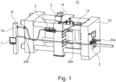
- the schematically illustrated device 10 for producing die-cast parts essentially comprises a die-casting mold 12 and a suction device 16.
- the die-casting mold 12 consists of a movable mold half 14 and a fixed mold half 15.
- the suction device 16 consists in particular of a suction line 20 and one with it connected vacuum pump 18. At the end of the suction line opposite the vacuum pump 18, this is connected to the movable mold half 14 and / or to the fixed mold half 15 of the die casting mold 12.
- two suction lines 20 are connected to the vacuum pump 18.
- the suction lines each end at the mold halves 14 and 15.
- Filter modules 2 are arranged in the suction line between the die casting mold 12 or between the mold halves and the vacuum pump 18.
- the mold vacuum valve is in Figure 1 not shown, it is located in the die casting mold near the connection of the suction line 20.
- the filters are arranged in the suction line and divide the suction line 20 into a first section, the line 20a, and a second section, the suction line 20b.
- a control 1 is only indicated by a screen.
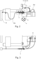
- the device is in Figure 2 as a side view and in Figure 3 shown as a top view, with the mold vacuum valve 21 being shown.
- the suction line 20 contains the following components: lines 20a from the mold vacuum valve 21 to the main valve, a filter module 2 and a suction line 20b between the filter module 2 and the vacuum pump 18.
- the suction line or the section of the line 20a begins close to or in the mold vacuum valve 21.
- the suction line consists of a special heat-resistant vacuum hose and continues to the filter module 2, through the filter module 2 via a vacuum hose to a hand valve, which is not shown, and the die-casting machine. From there the line leads into a vacuum line system and ends at the vacuum pump station.
- the filter module 2 is designed as a compact component and has different tasks.
- the filter module is in Figure 4 shown enlarged.
- the filter module has a connection on the input and output sides that can be connected to 1 or 2-inch connectors via screw connections 100.
- the compact filter module 2 can be connected to the hoses of the vacuum system via these screw connections.
- a filter housing 102 is connected via a reducing double nipple 101. Knurled screws 103 can be seen on the filter housing, which connect the filter housing, which consists of a base 102a and a cover 102b.
- a pressure sensor 104 Connected to the filter is a pressure sensor 104, which is connected via a reduction 105.
- a pressure gauge 106 is attached downstream.
- a 2/2-way valve 108 i.e. a valve with two controlled connections and two switching positions, is located in the filter module via clamps 107 and screw connections. This valve serves as the main valve.
- the residual moisture measurement is housed in the 2/2-way valve, which protrudes into a reference room as in the prior art.
- the reference space reflects the environmental parameters of the state that prevailed when the die casting process was completed and the evacuation of the die casting mold 12 was completed.
- All sensors, the pressure sensors and the residual moisture sensors are connected directly or indirectly to the control unit 1.
- the valves are also connected to this control unit 1, with the control unit controlling the entire casting process with all components in accordance with the measured values determined.
- the filter itself used in the filter module consists of a filter housing 102, which consists of a base 102a and a cover 102b.
- the two components are connected with the knurled screws 103 so that the housing components can be separated in a simple manner.
- an O-ring 205 rests on a flat peripheral surface of the housing parts, which is connected to a groove with three knurled screws that are attached equidistant from one another to guide the O-ring.
- the expert can of course also use any other number of knurled screws. The use of the knurled screws greatly simplifies the maintenance of the filter, as the filter can be opened by a person without the use of tools.
- the filter insert 200 is as shown in Figure 6 shown in section from a metal cylinder, which is closed by two perforated disks 201.
- a fine filter 203 and a coarse filter 204 are attached between the two perforated disks 201.
- a safety ring is used to fix the fine filter and the coarse filter in the metal cylinder.
- the coarse filter is made of steel filter wool and can be cleaned by knocking out the dirt from the casting process.
- the fine filter is cleaned with benzene or a suitable cleaning agent. It is important that the coarse side of the filter with the steel wool filter faces towards the mold vacuum valve and the fine filter faces towards the solenoid valve.
- the filter insert change intervals depend on the amount of dirt deposited during a production shift. With heavy use, hourly filter insert changes are definitely manageable.
- the filter combination of a coarse filter and a fine filter reduces the entry of dirt from the casting process towards the sensors to a minimum.
- the filter housing 102 is equipped with a pressure gauge that displays the actual value of the vacuum during the emptying phase; the final value represents the vacuum level in the cavity.
- the filter housing 102 has an integrated 1/2 inch opening for connecting the sensor 104 for measuring and recording the pressure.
- the analog output signal of the sensor is transmitted to the control unit 1.
- the filter module with solenoid valve and other components works much less wear and tear than without filters, as they can be easily replaced and/or cleaned.
- the machine according to the invention for producing die-cast parts also requires at least one positive valve for the suction device near the casting mold.
- Suitable valves are, for example, hydraulic valves in the DE3002886 A1 described.
- valve forms such as pneumatic valves or washboard valves, which are used to quickly reduce the pressure in the mold.
- Pneumatic valves have systemic problems. Compared to hydraulic drives, the pneumatic forces and moments are significantly lower and pneumatic cylinder movements always occur point-to-point. The end position is defined by a fixed stop. This requires pneumatic valves to be located very close to the mold, which increases wear on these components.
- Washboard valves are referred to as an "open venting system": The venting performance of the valve is primarily determined by the gap size between the valve halves and the valve width. These valves are often used in combination with a position-controlled or time-controlled valve.
- valves as mold vacuum valves, does not limit the performance of the device according to the invention. Rather, different types of valves can be used. In addition, a die casting machine does not necessarily have to be equipped with one type of valve; combinations of different valve types are also permitted.
- the device according to the invention has a control unit 1, which processes all of the measured values of the device and with which all hydraulic and pneumatic systems are controlled.
- a hydraulic control unit 3 controls the pressure cylinder from the insertion of the valve actuation insert until the opening and closing of the form valve using control bolts.
- the integrated directional spool valve Y3 serves as a safety valve to automatically release the accumulator pressure when the system is switched off.
- the diaphragm accumulator is intended for a constant pressure to move the hydraulic cylinder and thus the insert for opening/closing the mold vacuum valve.
- the device for producing die-cast parts also has a modular control system.
- the control 1 has inputs for recording all measurement data collected on the device and control outputs for suction sections and subunits such as the hydraulic control 3 and the pneumatic control 3 '.
- the control is designed to be compatible with different components and valve shapes.
- the control can control different types of valves in parallel, such as a hydraulic and a pneumatic valve. Replacing one type of valve with another type is easy in this way, as only the associated control module is activated and adjusted.
- the control is implemented in a control cabinet with PLC control.
- the control allows a reliable query based on the piston position of the mold valve to detect the closed state of the valve.
- the shutter position can also be adjustable and variable without determining the position by measuring the firing movement and is thus controlled by the control via fixed time sequences.
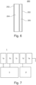
- FIG 7 The control is shown schematically.
- the actual software is shown modularly as software components 1a, 1b, 1c, 1d, 1e.
- the software is suitable for operating individual modules together while unwanted modules remain inactive.
- the software modules 1a...1e control two control units 3 and 3' via data connections. These are either control units for valves of the same or different types.
- the control unit 3 can be a control unit for hydraulic mold vacuum valves, while the control unit 3 'can be a control unit for pneumatic valves.
- the control also optionally controls the vacuum units and the actual die casting machine.
Landscapes
- Engineering & Computer Science (AREA)
- Mechanical Engineering (AREA)
- Chemical & Material Sciences (AREA)
- Chemical Kinetics & Catalysis (AREA)
- Molds, Cores, And Manufacturing Methods Thereof (AREA)
- Moulds For Moulding Plastics Or The Like (AREA)
Description
- Die vorliegende Erfindung betrifft eine Vorrichtung mit Filtermodul zur Herstellung von Druckgussteilen mit einer Druckgießform und einer zur gesteuerten Evakuierung eines Formhohlraumes vorgesehenen Absaugvorrichtung, welche aus einer Vakuumeinheit und einer die Vakuumeinheit und die Druckgießform verbindenden Saugleitung besteht.
- Eine gattungsgemäße Vorrichtung zur Herstellung von Druckgussteilen ist aus der
DE 30 02 886 C2 bekannt. Bei dieser wie auch bei anderen bekannten Druckgießmaschinen mit Absaugvorrichtungen zum Entlüften der Gießformen erfolgt die letzte Formfüllung mit flüssigem Metall im Zusammenwirken mit der Evakuierung der Form innerhalb weniger Millisekunden. Ziel ist es dabei, ein möglichst hohes Vakuum in dem Formhohlraum der Gießform zu erreichen, um eine möglichst hohe Qualität des Gussteiles zu erreichen. - Die
EP 0 600 324 A1 beschreibt ein Verfahren zur Herstellung eines Vakuums bei einer Vakuum-Druckgießmaschine, bei welchem das an die Druckgießform anzulegende Vakuum während des Gießprozesses einer Regelung unterziehbar ist. Dabei wird das über ein Vakuumventil angelegte Vakuum mittels eines Schaltventils so in seinem Druckverlauf geregelt, dass sich der Druck im Formhohlraum, in der Gießkammer und im Saugrohr nach einer bestimmten einstellbaren Funktion pro Zeiteinheit regelt. Der Unterdruck wird über eine Vakuummesssonde erfasst, die den Druck in einer Vakuum-Anschlussleitung misst. - Bei einem Druckgießverfahren ist es aber auch erforderlich, Trenn- und Schmierstoffe einzusetzen. Diese Zusätze haben in erster Linie die Aufgabe, eine Trennschicht zwischen dem flüssigen Metall und der Kontur der Gießform zu erzeugen, so dass ein Anhaften des Metalls an der Gießform verhindert wird. Dies tritt insbesondere beim Aluminiumguss aufgrund der hohen Affinität des Aluminiums zum Eisen der Gießform auf. Üblicherweise werden für die Erzeugung der genannten Sperrschicht wassermischbare Trennmittel eingesetzt. Durch diese Trennmittel wird zusätzlich eine Kühlung oder Temperierung der Druckgießform erreicht.
- Nachteilig an diesen Vorrichtungen bzw. Verfahren ist jedoch, dass nach Herausnahme des Gussteiles ein neuerlicher Trennmittelauftrag erforderlich ist und beim Trockenblasen der Gießform eine Restfeuchte im Formenhohlraum verbleibt. Zwar kann durch den sich anschließenden Evakuierungsvorgang der Gießform diese Restfeuchte zu einem gewissen Prozentsatz aus dem Formenhohlraum gemeinsam mit anderen beim Gießvorgang entstehenden Gasen abgesaugt werden, allerdings verbleibt immer ein gewisser Restfeuchteanteil in der Gießform. Diese in der Druckgießform verbleibende Restfeuchte reagiert aber bei einem anschließenden Gießvorgang mit dem flüssigen Metall wiederum unter Gasbildung. Letztere wirkt sich dann in Form von Porosität oder Lunkern im fertigen Gussteil aus. Dadurch ergibt sich eine erhebliche Qualitätsminderung des fertigen Gussteiles.
- Aus der
EP0819487B1 ist eine Vorrichtung zur Herstellung von Druckgussteilen bekannt, die zwei in einer Saugleitung angeordnete Ventile aufweist. Die beiden parallel geschalteten Ventile stellen die Verbindung zwischen einem Vakuumtank und einer Druckgießform her bzw. unterbrechen diese. Durch das Verschließen der beiden Ventile entsteht ein sogenannter Referenzraum in der Saugleitung. Dieser Referenzraum gibt den Zustand wieder, der geherrscht hat, als der letzte Evakuierungsprozess der Druckgießform beendet wurde. Dadurch ist es auf einfache Weise möglich, verschiedenste, für die Qualität des Druckgusses entscheidende Parameter, insbesondere den Restfeuchtegehalt im System zu bestimmen und die Vorrichtung entsprechend zu steuern. - Aus der
DE10022560 A1 ist eine Druckgießanordnung bekannt, die eine Drucküberwachung am Entlüftungskanal aufweist, der ein Ventil und ein Filter besitzt. - Alle Komponenten des Systems vor allem Ventile und Sensoren unterliegen einem starken Verschleiß und sind wartungsintensiv.
-
JP 2000-343 194 A -
CN 2 617 500 Y zeigt eine Vakuumgießmaschine, wobei ein erster Filter und ein zweiter Filter auf der Rohrleitung zwischen einem Formvakuumventil und dem Vakuumspeicher einer Vakuumluftpumpe angeordnet sind. Zwischen den beiden Filtern befindet sich ein Steuerelement, das das Öffnen und Schließen der Rohrleitung steuern kann. Zusätzlich sind zwischen dem ersten Filter und dem Steuerelement eine Hochdruck-Luftleitung und ein Steuerelement angeordnet, das das Öffnen und Schließen der Hochdruck-Luftleitung steuern kann. Der erste und der zweite Filter sind von der mechanischen Konstruktion, die einfach zu demontieren und zu montieren ist, wodurch die Vorteile eines effizienten Schutzes der Nutzungsdauer und der Lebensdauer der Vakuum-Luftpumpe sowie der schnellen Demontage und Reinigung des Filters erreicht werden können. - Aus der
DE4313800 A1 ist ein Verfahren zur Steuerung einer Druckgussvorrichtung mit gesteuerter Evakuierung bekannt. Diese Steuerung ist zentral, weist aber keine Module auf, die für verschiedene Aufgaben vorgesehen sind. - Aus der
DE 20 2004 017 551 U1 ist eine Steuerungsanlage für hydraulische und pneumatische Komponenten bekannt. - Es ist Aufgabe der vorliegenden Erfindung, eine verbessertes Filtermodul bereitzustellen, welches die Komponenten schützt und/oder einer schnellen Wartung zugänglich macht.
- Es ist Aufgabe der vorliegenden Erfindung, eine verbesserte Vorrichtung mit Filtermodul zur Herstellung von Druckgussteilen bereitzustellen, welches die Komponenten schützt und/oder einer schnellen Wartung zugänglich macht.
- Die Aufgabe wird auch gelöst mit einer Vorrichtung zur Herstellung von Druckgussteilen mit einer Druckgießform und einer zur gesteuerten Evakuierung eines Formhohlraums vorgesehenen Absaugvorrichtung, welche mindestens aus einer Vakuumeinheit und aus mindestens einer die Druckgießform verbindenden Saugleitung besteht, wobei die Saugleitung an einem Formvakuumventil im Formhohlraum endet, wobei die Vorrichtung mit einer zentralen Steuerung verbunden ist, und in der mindestens einen Saugleitung ein Filtermodul eingesetzt ist, das mindestens einen Filter, einen Feuchtesensor und einen Drucksensor enthält, wobei das Filtermodul so eingebaut ist, dass das Verbindungsstück zwischen Filtermodul und Formvakuumventil, eine Leitung, kürzer als eine Absaugleitung zwischen Filtermodul und Vakuumpumpe ist, wobei das Filtermodul einen Filtereinsatz und mindestens ein Filtergehäuse bestehend aus Boden und Deckel enthält, wobei Boden und Deckel über mindestens zwei Rändelschrauben miteinander dicht verbunden sind und einen Bauraum für den Filtereinsatz bilden.
- Durch den Einsatz eines Filtermoduls, das mehrere Funktionen in einem Bauteil integriert, ist es gelungen, die Vorrichtung zur Herstellung von Druckgussteilen so aufzubauen, dass eine einfache Wartung möglich ist. Das Filtermodul integriert dabei mehrere Funktionen wie die Filterfunktion und Messfunktionen in einem Bauteil, so dass die Vorrichtung mit dem Filtermodul einfach ausgestattet werden kann.
- Es ist von Vorteil, dass das Filtermodul so eingebaut ist, dass das Verbindungsstück zwischen Filter und Formvakuumventil, die Leitung, kürzer als die Absaugleitung zwischen Filter und Vakuumpumpe ist. Dadurch kann das Filtermodul möglichst nah am eigentlichen Formhohlraum angebracht sein, was eine Optimierung der Messungen der Parameter im Formhohlraum ermöglicht.
- Durch den Aufbau mit Rändelschrauben kann das Filtergehäuse einfach gewartet werden. Es ist zum Öffnen und Schließen kein Werkzeug notwendig, und der Produktionsprozess wird dadurch nur kurz unterbrochen.
- Es ist von Vorteil, dass Boden und Deckel über einen O-Ring dicht miteinander verbunden sind, wobei die O-Ring- Dichtung eine zuverlässige Dichtung darstellt, die auch bei häufiger Wartung zuverlässig dichtet.
- Es ist weiterhin von Vorteil, dass der Filtereinsatz aus einem von zwei Lochscheiben stirnseitig begrenzten Metallzylinder ausgebildet ist, sodass der gesamte Filtereinsatz auf einfache Art und Weise aus dem Filtergehäuse entnommen werden kann.
- Der Filtereinsatz enthält mindestens einen Feinfilter und einen Grobfilter im Metallzylinder, so dass Rückstände aus dem Gießprozess in den Filtern abgeschieden werden können.
- Dabei sind die Feinfilter und Grobfilter mit einem Sicherungsring im Metallzylinder gesichert.
- Das Filtermodul integriert dabei mehrere Funktionen wie die Filterfunktion und Messfunktionen in einem Bauteil, so dass die Vorrichtung mit dem Filtermodul einfach ausgestattet werden kann.
- Vorteilhafterweise sitzt das Filtermodul zwischen Gusswerkzeug und einer Messeinrichtung.
- Einsetzbar ist die erfindungsgemäße Lösung vorteilhafterweise in Vorrichtungen, in denen die Druckgießform aus einer beweglichen Formhälfte und einer fest angeordneten Formhälfte besteht.
- Je nach Ausführungsform der Druckgießmaschine ist es von Vorteil, dass die Saugleitung an der beweglichen Formhälfte oder der festen Formhälfte befestigt ist.
- Die Vorrichtung weist den Vorteil auf, dass die Formvakuumventile unterschiedliche Typen von Ventilen sind. Damit ist es möglich Ventile an ganz unterschiedlichen Druckgießmaschinen einzusetzen, die auch unterschiedliche Ventiltypen verwenden. Ein Austausch der Ventiltypen beispielsweise eines pneumatischen Ventils durch ein hydraulisches Ventil ist auf einfache Weise möglich.
- Vorteilhafterweise ist die Steuerung dazu ausgelegt mindestens einen Typen von Formvakuumventilen anzusteuern.
- Dabei ist die Steuerung für eine Vorrichtung zur Herstellung von Druckgussteilen aus mit einer Druckgießform und einer zur gesteuerten Evakuierung eines Formhohlraums vorgesehenen Absaugvorrichtung eingerichtet, wobei die Vorrichtung mit einer zentralen Steuerung verbunden ist, wobei die Steuerung eine Steuereinheit aufweist, bei der mindestens ein Modul mit der Vorrichtung zur Herstellung von Druckgussteilen und weitere Module mit mindestens einer hydraulischen und/ oder pneumatischen Einheit für die Ansteuerung von Ventilen verbunden sind.
- Die Steuerung ist dabei besonders flexibel und an die Notwendigkeiten unterschiedlicher Anlagen anpassbar.
- Es ist von Vorteil, dass das mindestens eine Modul für die hydraulische Einheit parallel mit dem mindestens einem Modul für die pneumatische Einheit betreibbar ist. Das erlaubt den Einsatz der Steuerung in gemischten Anlagen, in denen unterschiedliche Bauteile aus der Hydraulik oder Pneumatik verwendet werden.
- Die Steuereinheit besitzt Komponenten zur Ansteuerung von Ventilen im Gusswerkzeug für den Einsatz von vakuumgestütztem Druckguss, wobei der Type der Ventile, also mechanisch, hydraulisch, pneumatisch austauschbar ist. Damit kann mit unterschiedlichen Modulen der Gemischtbetreib der Vorrichtung erfolgen.
- Es ist von Vorteil, wenn die Komponenten zur Ansteuerung von Ventilen aus Softwarekomponenten bestehen. Die Steuereinheit weist Eingänge für alle an der Vorrichtung erhobenen Messdaten auf.
- Weitere Einzelheiten, Merkmale und Vorteile der Erfindung ergeben sich aus der folgenden Beschreibung eines zeichnerisch dargestellten Ausführungsbeispiels.
- Darin zeigen:
-
Figur 1 eine dreidimensionale Darstellung der Vorrichtung, -
Figur 2 eine schematische Darstellung der erfindungsgemäßen Vorrichtung zur Herstellung von Druckgussteilen in Seitenansicht; -
Figur 3 eine schematische Darstellung der erfindungsgemäßen Vorrichtung zur Herstellung von Druckgussteilen in Aufsicht, -
Figur 4 einen Schnitt durch ein Filtermodul -
Figur 5 eine schematische Darstellung eines Filters, -
Figur 6 einen Schnitt durch einen Filtereinsatz -
Figur 7 ein Schema einer Steuereinheit - Eine in der
Figur 1 schematisch dargestellte Vorrichtung 10 zur Herstellung von Druckgussteilen umfasst im Wesentlichen eine Druckgießform 12 und eine Absaugvorrichtung 16. Die Druckgießform 12 besteht dabei in diesem Beispiel aus einer beweglichen Formhälfte 14 und einer festen Formhälfte 15. Die Absaugvorrichtung 16 besteht insbesondere aus einer Saugleitung 20 und einer damit verbundenen Vakuumpumpe 18. An dem der Vakuumpumpe 18 gegenüberliegendes Ende der Saugleitung ist diese mit der beweglichen Formhälfte 14 und/oder mit der feststehenden Formhälfte 15 der Druckgießform 12 verbunden. Im Ausführungsbeispiel sind 2 Saugleitungen 20 mit der Vakuumpumpe 18 verbunden. Die Saugleitungen enden jeweils an den Formhälften 14 und 15. - Zwischen der Druckgießform 12, bzw. zwischen den Formhälften und der Vakuumpumpe 18 sind Filtermodule 2 in der Saugleitung angeordnet. Das Formvakuumventil ist in
Figur 1 nicht dargestellt, es befindet sich in der Druckgießform in der Nähe des Anschlusses der Saugleitung 20. Die Filter sind in der Saugleitung angeordnet und teilen die Saugleitung 20 in einen ersten Abschnitt, der Leitung 20a und einen zweiten Abschnitt, der Absaugleitung 20b. Eine Steuereinheit 3, die in diesem Beispiel über hydraulische Anschlüsse mit dem Formvakuumventil verbunden ist, ist an der Druckgussmaschine angebracht. Eine Steuerung 1 ist dabei lediglich durch einen Bildschirm angedeutet. - Die Vorrichtung ist in
Figur 2 als Seitenansicht und inFigur 3 als Aufsicht dargestellt, wobei das Formvakuumventil 21 dargestellt ist. - Die Saugleitung 20 enthält folgenden Bauteilen: Leitungen 20a vom Formvakuumventil 21 zum Hauptventil, ein Filtermodul 2 sowie eine Absaugleitung 20b zwischen Filtermodul 2 und Vakuumpumpe 18.
- Die Saugleitung bzw. der Abschnitt der Leitung 20a beginnt nahe am oder im Formvakuumventil 21.
- Die Saugleitung besteht aus einem besonderen hitzebeständigen Unterdruckschlauch und setzt sich zu dem Filtermodul 2, durch das Filtermodul 2 über einen Unterdruckschlauch zu einem Handventil, das nicht dargestellt ist, und der Druckgussmaschine fort. Von dort führt die Leitung in ein Vakuumleitungssystem und endet an der Vakuumpumpenstation.
- Das Filtermodul 2 ist als ein kompaktes Bauteil ausgebildet und hat unterschiedliche Aufgaben.
- Das Filtermodul wird dabei in
Figur 4 vergrößert dargestellt. - Eingangsseitig und ausgangsseitig weist das Filtermodul einen Anschluss auf, der über Verschraubungen 100 mit 1 oder 2-Zoll Verbindungsstücken verbunden werden kann. Über diese Verschraubungen ist das kompakte Filtermodul 2 mit der Verschlauchung des Vakuumsystems verbindbar.
- Über einen Reduzierdoppelnippel 101 ist ein Filtergehäuse 102 angebunden. Am Filtergehäuse sind Rändelschraube 103 zu erkennen, die das Filtergehäuse, das aus einem Boden 102a und einem Deckel 102b besteht, verbinden.
- An das Filter angeschlossen ist ein Drucksensor 104, der über einen Reduzierung 105 angeschlossen ist.
- Nachgeordnet ist ein Manometer 106 angebracht. Über Schellen 107 und Verschraubungen sitzt ein 2/2-Wegeventil 108, also ein Ventil mit zwei gesteuerten Anschlüssen und zwei Schaltstellungen im Filtermodul. Dieses Ventil dient als Hauptventil.
- Im 2/2 Wegeventil ist die die Restfeuchtemessung untergebracht, die wie im Stand der Technik in einen Referenzraum ragt.
- Der Referenzraum gibt die Umgebungsparameter des Zustandes wieder, der geherrscht hat, als der Druckgießvorgang abgeschlossen und die Evakuierung der Druckgießform 12 abgeschlossen wurde.
- Alle Sensoren, die Drucksensoren und die Restfeuchtesensoren sind direkt oder indirekt mit der Steuereinheit 1 verbunden. Auch die Ventile sind mit dieser Steuereinheit 1 verbunden, wobei die Steuereinheit den gesamten Gießprozess mit allen Komponenten entsprechend der ermittelten Messwerte kontrolliert.
- Der im Filtermodul eingesetzte Filter selbst besteht aus einem Filtergehäuse 102, das aus einem Boden 102a und einem Deckel 102b besteht. Die beiden Komponenten sind dabei mit den Rändelschrauben 103 verbunden, so dass die Gehäusebauteile auf einfache Art und Weise getrennt werden können. Um die Gehäuseteile 102a und 102b zu dichten, liegt ein O-Ring 205 an einer planen Umfangsflächen der Gehäuseteile an, die zur Führung des O-Rings eine Rille aufweise drei Rändelschrauben, die äquidistant zueinander angebracht sind, verbunden. Der Fachmann kann natürlich auch jede andere Zahl an Rändelschrauben verwenden. Der Einsatz der Rändelschrauben vereinfacht die Wartung des Filters sehr, da das Filter ohne Einsatz eines Werkzeugs von einem Menschen geöffnet werden kann.
- Wenn die beiden Bauteile, wie in
Figur 5 gezeigt, getrennt sind, erkennt man im Inneren einen Filtereinsatz 200. Der Filtereinsatz besteht wie inFigur 6 im Schnitt gezeigt aus einem Metallzylinder, der von zwei Lochscheiben 201 abgeschlossen wird. Zwischen den beiden Lochscheiben 201 sind ein Feinfilter 203 und ein Grobfilter 204 angebracht. Zur Fixierung des Feinfilters und des Grobfilters im Metallzylinder dient ein Sicherheitsring. - Der Grobfilter besteht aus Stahlfilterwolle und kann durch Herausklopfen des Schmutzes aus dem Gießprozess gesäubert werden.
- Der Feinfilter wird mit Benzol oder einem geeigneten Reinigungsmittel gereinigt. Es ist wichtig, dass die grobe Seite des Filters mit dem Stahlwollfilter in Richtung des Formvakuumventils und das Feinfilter in Richtung des Magnetventils weist.
- Die Wechselintervalle des Filtereinsatzes hängen vom Umfang der während einer Produktionsschicht abgelagerten Schmutzteile ab. Bei starkem Einsatz sind stündliche Filtereinsatzwechsel durchaus handhabbar.
- Die Filterkombination aus einem Grobfilter und einem Feinfilter reduziert den Eintrag von Schmutz aus dem Gießprozess in Richtung der Sensoren auf ein Mindestmaß.
- Das Filtergehäuse 102 ist mit einem Druckmesser ausgestattet, der den Istwert des Vakuums während der Entleerungsphase anzeigt, der Endwert stellt hierbei das Vakuumniveau im Hohlraum dar.
- Das Filtergehäuse 102 verfügt integriert über eine 1/2-Zoll-Öffnung zum Anschluss des Sensors 104 zur Messung und Aufzeichnung des Druckes.
- Das analoge Ausgangssignal des Sensors wird an die Steuereinheit 1 übertragen. Das Filtermodul mit Magnetventil und weiteren Bauteilen arbeitet durch den Einsatz der Filter wesentlich verschleißfreier als ohne Filter, da diese auf einfache Art und Weise ersetzt und/oder gereinigt werden können.
- Die erfindungsgemäße Maschine zur Herstellung von Druckgussteilen verlangt weiterhin mindestens ein formschlüssiges Ventil zur Absaugvorrichtung nahe der Gießform.
- Bei Druckgießmaschinen mit Absaugvorrichtungen zum Entlüften der Formen erfolgt die letzte Formfüllung mit flüssigem Metall im Zusammenwirken mit der Evakuierung der Form innerhalb weniger Millisekunden. Zur Erzielung eines möglichst hohen Vakuums ist es demnach zweckmäßig, den zum Evakuieren dienenden, mit der Form in Verbindung stehenden Saugkanal möglichst spät zu schließen, d.h. kurz bevor das flüssige Metall in das Saugsystem einspritzen kann. Geeignete Ventile werden zum Beispiel als hydraulische Ventile in der
DE3002886 A1 beschrieben. - Es gibt alternative Ventilformen, wie beispielsweise pneumatische Ventile oder Waschbrettventile, die verwendet werden, um den Druck in der Gießform schnell zu reduzieren.
- Pneumatische Ventile haben systembedingte Probleme. Im Vergleich zu hydraulischen Antrieben sind die pneumatischen Kräfte und Momente wesentlich geringer und pneumatische Zylinderbewegungen erfolgen stets Punkt-zu-Punkt. Die Endposition wird jeweils durch einen Festanschlag definiert. Dadurch müssen pneumatische Ventile sehr nahe an der Gießform angebracht sein, was den Verschleiß dieser Komponenten erhöht.
- Waschbrettventile werden als "offenes Entlüftungssystem" bezeichnet: Die Entlüftungsleistung des Ventils wird vorwiegend durch die Spaltgröße zwischen den Ventilhälften und die Ventilbreite bestimmt. Diese Ventile werden oft in Kombination mit einem weg- oder zeitgesteuerten Ventil eingesetzt.
- Der Typus der Ventile, als Formvakuumventile, begrenzt die Leistung der erfindungsgemäßen Vorrichtung nicht. Vielmehr ist es so, dass unterschiedliche Ventiltypen einsetzbar sind. Darüber hinaus muss eine Druckgießmaschine nicht zwangsweise mit einem Ventiltypen ausgestattet sein, sondern es sind auch Kombinationen unterschiedlicher Ventiltypen erlaubt.
- Die erfindungsgemäße Vorrichtung weist einen Steuereinheit 1 auf, die alle Messwerte der Vorrichtung verarbeitet und mit der alle hydraulischen, pneumatischen Systeme angesteuert werden.
- Eine hydraulische Steuereinheit 3 steuert bei einem hydraulischen Ventil den Druckzylinder vom Einsetzen des Einsatzstückes der Ventilbetätigung bis zum Öffnen und Schließen des Formventils mittels Steuerbolzen.
- Diese beispielhafte hydraulische Steuereinheit 3 ist an einer Verteilerplatte 4 angeschraubt. Auf der Verteilerplatte befinden sich die folgenden Anschlüsse:
- P = Betriebsdruck der Druckgussmaschine (min 120-160 Bar);
- T = Tankrohr (0 Bar);
- A = Zylinder ausrücken = offenes Ventil (mit 120-160 Bar);
- B = Zylinder einrücken = geschlossenes Ventil. (mit einem Speicherdruck von ca. 95-100 Bar)
- Ein Regelventil Y1 , ein Wegeschieberventil Y2 mit einem Patronenrückschlagventil im P-Rohr von Y2, ein Wegeschieberventil Y3, ein Druckminderventil (≈ 95 - 100 Bar), ein Membranspeicher (Po-= 60 Bar Stickstoff) und ein Patronenrückschlagventil im P-Rohr der Grundplatte sind in einer Steuereinheit 3 in einem einzigen Gehäuse integriert.
- Das integrierte Wegeschieberventil Y3 dient als Sicherheitsventil zum automatischen Ablassen des Speicher-Druckes beim Ausschalten der Anlage. Der Membranspeicher ist für einen konstanten Druck zum Bewegen des Hydraulikzylinders und damit des Einschubs zum Öffnen / Schließen des Formvakuumventils vorgesehen.
- Die Vorrichtung zur Herstellung von Druckgussteilen weist zudem eine modular aufgebaute Ansteuerung auf. Die Steuerung 1 besitzt Eingänge für die Erfassung aller an der Vorrichtung erhobenen Messdaten und Ansteuerausgänge für Saugstrecken und Untereinheiten wie der hydraulischen Steuerung 3 und der pneumatischen Steuerung 3'. Die Steuerung ist so aufgebaut, dass sie mit unterschiedlichen Bauelementen und Ventilformen kompatibel gestaltet ist. Die Steuerung kann parallel verschiedenen Typen von Ventilen, wie ein hydraulisches und ein pneumatisches Ventil ansteuern. Ein Ersatz eines Ventiltyps durch einen anderen Typen ist auf diese Art einfach, da lediglich das dazugehörige Steuerungsmodul aktiviert und angepasst wird.
- Mit der erfindungsgemäßen Steuerung sind mehrere Formevakuierungslinien und Schnellvakuumlinien ansteuerbar.
- Umgesetzt wird die Steuerung in einem Schaltschrank mit PLC Steuerung. Die Steuerung erlaubt eine sichere Abfrage basierend auf der Kolbenposition des Formventils, um den Schließzustand des Ventils zu detektieren.
- Die Verschlussposition kann aber auch ohne Positionsbestimmung durch Messung in der Schussbewegung einstellbar und variabel sein und wird so von der Steuerung über festvorgegebene Zeitabläufe angesteuert.
- In
Figur 7 ist die Steuerung schematisch dargestellt, Die eigentliche Software ist modular als Softwarekomponenten 1a, 1b, 1c, 1d, 1e gezeigt. Die Software ist dazu geeignet, einzelne Module zusammen zu betreiben, während nicht gewünschte Module inaktiv bleiben. - Die Softwaremodule 1a...1e steuern in diesem Beispiel über Datenverbindungen zwei Steuereinheiten 3 und 3' an. Dabei handelt es sich entweder um Steuereinheiten für Ventile gleichen oder unterschiedlichen Typus. So kann die Steuereinheit 3 eine Steuereinheit für hydraulische Formvakuumventile sein, die Steuereinheit 3' dagegen eine Steuereinheit für pneumatische Ventile. Die Steuerung steuert darüber hinaus optional die Vakuumeinheiten sowie die eigentliche Druckgießmaschine.
- Das Verfahren zur Herstellung von Druckgussteilen ist durch folgende Verfahrensschritte charakterisiert:
- a) Evakuierung einer Druckgießform,
- b) Füllen der Druckgießform mit Gießmaterial,
- c) Entnehmen des Druckgussteiles,
- e) Messungen von Umgebungsparameter im Filtermodul und
- f) entsprechend dem Ergebnis dieser Messungen eine Vorrichtung zur Herstellung von Druckgussteilen gesteuert.
- Dadurch ist gewährleistet, dass das Verfahren entsprechend den tatsächlichen Umgebungsparametern in der Druckgießform gesteuert und auf entsprechende optimierte Umgebungsparameter normiert werden kann. So ist es möglich, den Gießprozess so einzustellen, dass die gemessene Restfeuchte ein je nach Druckgießform und -teil typisches Minimum erreicht und das Verfahren in einen stabilen Zustand übergeht.
-
- 1
- Steuereinheit
- 1a, 1b, 1c, 1d, 1e
- Steuermodule
- 2
- Filtermodul
- 3
- Steuermodul
- 4
- Verteilerplatte
- 10
- Vorrichtung
- 12
- Druckgießform
- 16
- Absaugvorrichtung
- 14
- Bewegliche Formhälfte
- 15
- Feste Formhälfte
- 18
- Vakuumpumpe
- 20
- Saugleitung
- 20a
- Leitung
- 20b
- Absaugleitung
- 21
- Formvakuumventil
- 100
- Verschraubung
- 101
- Reduzierdoppelnippel
- 102
- Filtergehäuse
- 102 a, b
- Boden und Deckel
- 103
- Rändelschraube
- 104
- Drucksensor
- 105
- Reduzierung
- 106
- Manometer
- 107
- Schelle
- 108
- 2/2 Wegeventil
- 200
- Filtereinsatz
- 202
- Lochscheiben
- 203
- Feinfilter
- 204
- Grobfilter
- 205
- O-Ring
Claims (6)
- Vorrichtung (10) zur Herstellung von Druckgussteilen mit einer Druckgießform (12) und einer zur gesteuerten Evakuierung eines Formhohlraums vorgesehenen Absaugvorrichtung, welche mindestens aus einer Vakuumeinheit (18) und aus mindestens einer die Druckgießform verbindenden Saugleitung besteht, wobei die Saugleitung an einem Formvakuumventil (21) im Formhohlraum endet, wobei die Vorrichtung mit einer zentralen Steuerung (1) verbunden ist, und in der mindestens einen Saugleitung ein Filtermodul (2) eingesetzt ist, das mindestens einen Filter, einen Feuchtesensor und einen Drucksensor enthält, wobei das Filtermodul (2) so eingebaut ist, dass das Verbindungsstück zwischen Filtermodul und Formvakuumventil, eine Leitung (20a), kürzer als eine Absaugleitung (20b) zwischen Filtermodul und Vakuumpumpe ist, dadurch gekennzeichnet,
dass das Filtermodul (2) einen Filtereinsatz (200) und mindestens ein Filtergehäuse (102) bestehend aus Boden (102a) und Deckel (102b) enthält, wobei Boden und Deckel über mindestens zwei Rändelschrauben (103) miteinander dicht verbunden sind und einen Bauraum für den Filtereinsatz (200) bilden. - Vorrichtung (10) mit Filtermodul (2) nach Anspruch 1, dadurch gekennzeichnet, dass Boden (102a) und Deckel (102b) über einen O-Ring dicht miteinander verbunden sind.
- Vorrichtung (10) mit Filtermodul (2) nach Anspruch 1oder 2, dadurch gekennzeichnet, dass der Filtereinsatz aus einem von zwei Lochscheiben (202) stirnseitig begrenzten Metallzylinder ausgebildet ist.
- Vorrichtung (10) mit Filtermodul (2) nach Anspruch 3, dadurch gekennzeichnet, dass der Filtereinsatz mindestens ein Feinfilter (203) und ein Grobfilter (204) im Metallzylinder enthält.
- Vorrichtung (10) mit Filtermodul (2) nach Anspruch 4, dadurch gekennzeichnet, dass die Feinfilter (203) und Grobfilter (204) mit einem Sicherungsring im Metallzylinder gesichert sind.
- Vorrichtung (10) mit Filtermodul (2) nach Anspruch 1 bis 5, dadurch gekennzeichnet, dass dadurch gekennzeichnet, dass das Filtermodul (2) zwischen Gusswerkzeug und einer Messeinrichtung eingebaut ist.
Applications Claiming Priority (5)
| Application Number | Priority Date | Filing Date | Title |
|---|---|---|---|
| DE102016221678.3A DE102016221678B4 (de) | 2016-11-04 | 2016-11-04 | Vorrichtung zur Herstellung von Druckgussteilen |
| DE102016221675.9A DE102016221675B4 (de) | 2016-11-04 | 2016-11-04 | Filtermodul für eine Vorrichtung zur Herstellung von Druckgussteilen |
| DE102016221674.0A DE102016221674B4 (de) | 2016-11-04 | 2016-11-04 | Steuerung für eine Vorrichtung zur Herstellung von Druckgussteilen |
| PCT/EP2017/076860 WO2018082939A2 (de) | 2016-11-04 | 2017-10-20 | Vorrichtung, steuerung und filtermodul zur herstellung von druckgussteilen, sowie verfahren dazu |
| EP17793615.0A EP3535078A2 (de) | 2016-11-04 | 2017-10-20 | Vorrichtung, steuerung und filtermodul zur herstellung von druckgussteilen, sowie verfahren dazu |
Related Parent Applications (2)
| Application Number | Title | Priority Date | Filing Date |
|---|---|---|---|
| EP17793615.0A Division EP3535078A2 (de) | 2016-11-04 | 2017-10-20 | Vorrichtung, steuerung und filtermodul zur herstellung von druckgussteilen, sowie verfahren dazu |
| EP17793615.0A Division-Into EP3535078A2 (de) | 2016-11-04 | 2017-10-20 | Vorrichtung, steuerung und filtermodul zur herstellung von druckgussteilen, sowie verfahren dazu |
Publications (2)
| Publication Number | Publication Date |
|---|---|
| EP3593924A1 EP3593924A1 (de) | 2020-01-15 |
| EP3593924B1 true EP3593924B1 (de) | 2023-09-13 |
Family
ID=60202031
Family Applications (2)
| Application Number | Title | Priority Date | Filing Date |
|---|---|---|---|
| EP19186006.3A Active EP3593924B1 (de) | 2016-11-04 | 2017-10-20 | Vorrichtung mit filtermodul zur herstellung von druckgussteilen |
| EP17793615.0A Pending EP3535078A2 (de) | 2016-11-04 | 2017-10-20 | Vorrichtung, steuerung und filtermodul zur herstellung von druckgussteilen, sowie verfahren dazu |
Family Applications After (1)
| Application Number | Title | Priority Date | Filing Date |
|---|---|---|---|
| EP17793615.0A Pending EP3535078A2 (de) | 2016-11-04 | 2017-10-20 | Vorrichtung, steuerung und filtermodul zur herstellung von druckgussteilen, sowie verfahren dazu |
Country Status (4)
| Country | Link |
|---|---|
| US (2) | US10994329B2 (de) |
| EP (2) | EP3593924B1 (de) |
| CN (2) | CN110328346A (de) |
| WO (1) | WO2018082939A2 (de) |
Families Citing this family (4)
| Publication number | Priority date | Publication date | Assignee | Title |
|---|---|---|---|---|
| US11179772B2 (en) | 2019-06-20 | 2021-11-23 | Midland Technologies, Inc. | Vacuum sensor system for high pressure die casting |
| CN112355269B (zh) * | 2020-11-03 | 2021-11-26 | 江苏富航钢结构有限公司 | 一种方便排气的薄壁件加工用压铸成型设备 |
| CN114012063A (zh) * | 2021-11-03 | 2022-02-08 | 昀昊精密模具五金(深圳)有限公司 | 刀具模具及其实现刀具精冲的方法 |
| DE102024121519A1 (de) * | 2024-07-29 | 2026-01-29 | InterGuss Gießereiprodukte GmbH | Entlüftungsvorrichtung, Gießvorrichtung mit Entlüftungsvorrichtung, Vakuumdruckgussanlage und Verfahren zum Betreiben der Vakuumdruckgussanlage |
Family Cites Families (34)
| Publication number | Priority date | Publication date | Assignee | Title |
|---|---|---|---|---|
| DE1161293B (de) | 1955-11-25 | 1964-01-16 | Bochumer Ver Fuer Gussstahlfab | Anlage zur Unterdruckbehandlung von Stahlschmelzen |
| GB1052810A (de) | 1963-11-14 | |||
| CH603218A5 (de) | 1976-03-10 | 1978-08-15 | Waelti Gebrueder Ag | |
| DE3002886A1 (de) | 1980-01-28 | 1981-07-30 | Bayrisches Druckguß-Werk Thurner KG, 8015 Markt Schwaben | Druckgiessmaschine und verfahren zum betrieb derselben |
| DE3340417A1 (de) | 1983-11-09 | 1985-05-15 | Gebrüder Lüngen GmbH & Co KG, 4006 Erkrath | Filterelement zum filtrieren von metallschmelzen |
| DE3841587A1 (de) | 1987-12-11 | 1989-07-27 | Gen Motors Corp | Fuehlermechanismus fuer die ventilstellung in einem formhohlraum-gasabfuehrsystem |
| US5125450A (en) | 1990-05-07 | 1992-06-30 | Electrovert Ltd. | Method of and system for controlling flow of molten liquid to cast metal alloys |
| US5219409A (en) | 1992-04-27 | 1993-06-15 | Outboard Marine Corporation | Vacuum die casting process |
| DE4239558A1 (de) | 1992-11-25 | 1994-05-26 | Mueller Weingarten Maschf | Verfahren zur Unterdruck-Herstellung bei einer Druckgießmaschine |
| DE19611817C2 (de) | 1996-03-26 | 2000-10-26 | Schako Metallwarenfabrik | Filterkasten |
| DE19628870A1 (de) * | 1996-07-17 | 1998-01-22 | Alusuisse Bayrisches Druckgus | Vorrichtung und Verfahren zur Herstellung von Druckgußteilen |
| JPH1157968A (ja) | 1997-08-22 | 1999-03-02 | Honda Motor Co Ltd | 真空ダイカスト装置 |
| DE19750496A1 (de) | 1997-11-14 | 1999-05-20 | Bosch Gmbh Robert | Verfahren zur Bestimmung der von einer Brennkraftmaschine angesaugten Luft und Sensor für eine Brennkraftmaschine |
| JP2000343194A (ja) * | 1999-05-31 | 2000-12-12 | Denso Corp | ダイカスト鋳造機及びダイカスト鋳造方法 |
| EP1057559B1 (de) * | 1999-05-31 | 2004-10-06 | Denso Corporation | Verfahren und Vorrichtung zum Druckgiessen unter Verwendung von Formtrennmitteln |
| MY130713A (en) | 2000-01-12 | 2007-07-31 | Nippon Light Metal Co | A die-casting process and a die-casting machine |
| DE10022560A1 (de) | 2000-05-10 | 2001-11-15 | Fuchs Lubritech Gmbh | Druckgießmaschine |
| ATE343443T1 (de) | 2001-09-21 | 2006-11-15 | Fondarex Sa | Entlüftungsventileinrichtung für giessformen |
| CN2617500Y (zh) | 2003-04-11 | 2004-05-26 | 尚富工业股份有限公司 | 压铸机模具抽真空的空气过滤系统 |
| ES2333705T3 (es) | 2003-08-25 | 2010-02-26 | Fondarex S.A. | Procedimiento de vacio para el moldeo por inyeccion o presion. |
| DE50306675D1 (de) * | 2003-10-15 | 2007-04-12 | Fondarex Sa | Druck- oder Spritzgiessmaschine |
| DE202004017551U1 (de) | 2004-11-10 | 2005-02-17 | Haupt, Steffen | Nutzerspezifizierbare Datenverarbeitungseinrichtung zur Unterstützung sowohl der Instandhaltung als auch der Kontrolle von Maschinen und Anlagen mit hydraulischen und/oder pneumatischen Komponenten |
| JP2007222896A (ja) | 2006-02-22 | 2007-09-06 | Aisin Seiki Co Ltd | キャビティ湿度計測方法およびダイカスト装置 |
| DE202009013507U1 (de) | 2009-07-31 | 2010-02-11 | Robert Bosch Gmbh | Hydraulische Steuerung mit Digitalhydraulik |
| CN201684909U (zh) | 2010-02-10 | 2010-12-29 | 张琬琳 | 成型模具用的气压差吸引真空装置 |
| DE102012008453A1 (de) | 2012-04-27 | 2013-10-31 | Mann + Hummel Gmbh | Filterelement und Gehäuse für ein Filterelement |
| DE102011089480A1 (de) | 2011-12-21 | 2013-06-27 | Robert Bosch Gmbh | Sensorvorrichtung zur Erfassung mindestens einer Eigenschaft eines strömenden fluiden Mediums |
| CN202639273U (zh) | 2012-04-16 | 2013-01-02 | 启东凯雷达模具制造有限公司 | 压铸模抽真空过滤装置 |
| DE102012220513B4 (de) | 2012-11-12 | 2023-02-16 | Bayerische Motoren Werke Aktiengesellschaft | Verfahren und Vorrichtung zur Herstellung eines Druckgussteils |
| JP5987674B2 (ja) | 2012-12-19 | 2016-09-07 | マツダ株式会社 | 鋳造装置および鋳造方法 |
| CH709493A2 (de) * | 2014-04-14 | 2015-10-15 | Fondarex Sa | Vorrichtung und Verfahren zur Messung der Feuchtigkeit in Druckgiessformen. |
| CN204353444U (zh) | 2014-12-18 | 2015-05-27 | 李杰红 | 一种压铸铝合金液的过滤装置 |
| CN204524225U (zh) * | 2015-04-22 | 2015-08-05 | 美诺精密压铸(上海)有限公司 | 排气型芯结构以及真空压铸系统 |
| CN105458212B (zh) | 2015-11-26 | 2017-12-15 | 重庆长安汽车股份有限公司 | 发动机缸体铸件缸孔隔皮清理工装 |
-
2017
- 2017-10-20 EP EP19186006.3A patent/EP3593924B1/de active Active
- 2017-10-20 US US16/346,412 patent/US10994329B2/en active Active
- 2017-10-20 CN CN201910650373.6A patent/CN110328346A/zh active Pending
- 2017-10-20 EP EP17793615.0A patent/EP3535078A2/de active Pending
- 2017-10-20 WO PCT/EP2017/076860 patent/WO2018082939A2/de not_active Ceased
- 2017-10-20 CN CN201780074621.6A patent/CN110099765A/zh active Pending
-
2019
- 2019-04-30 US US16/399,722 patent/US10994330B2/en active Active
Also Published As
| Publication number | Publication date |
|---|---|
| CN110099765A (zh) | 2019-08-06 |
| WO2018082939A2 (de) | 2018-05-11 |
| EP3593924A1 (de) | 2020-01-15 |
| US20190255603A1 (en) | 2019-08-22 |
| WO2018082939A3 (de) | 2018-08-16 |
| US20190255604A1 (en) | 2019-08-22 |
| CN110328346A (zh) | 2019-10-15 |
| EP3535078A2 (de) | 2019-09-11 |
| US10994329B2 (en) | 2021-05-04 |
| US10994330B2 (en) | 2021-05-04 |
Similar Documents
| Publication | Publication Date | Title |
|---|---|---|
| DE69208607T2 (de) | Energiespar- und Überwachungsystem für pneumatische Ventile | |
| DE69104367T2 (de) | Ausgabeverfahren und -vorrichtung, insbesondere für dichtungs-/klebemittel. | |
| EP2435713B1 (de) | Verfahren zum entfernen von fremdstoffen aus einem digitalhydraulischen druckregler eines hydrauliksystems | |
| DE3730837C2 (de) | Entlüftungseinrichtung zur Verwendung in einer Gießmaschine | |
| EP3593924A1 (de) | Filtermodul in einer vorrichtung zur herstellung von druckgussteilen | |
| DE4313800B4 (de) | Vakuumdruckgussverfahren | |
| DE102016221678B4 (de) | Vorrichtung zur Herstellung von Druckgussteilen | |
| DE102007062131B4 (de) | Einspannvorrichtung für eine Aufhängemaschine zum Aufhängen wurstförmiger Produkte | |
| EP0819487A1 (de) | Vorrichtung und Verfahren zur Herstellung von Druckgussteilen | |
| CH659783A5 (de) | Verfahren und vorrichtung zum steuern einer stranggiessanlage. | |
| DE102016221674B4 (de) | Steuerung für eine Vorrichtung zur Herstellung von Druckgussteilen | |
| DE102016221675B4 (de) | Filtermodul für eine Vorrichtung zur Herstellung von Druckgussteilen | |
| DE102019105819B3 (de) | Vorrichtung zur Herstellung von Kernen aus Formstoff | |
| DE102009006973B4 (de) | Anfahrventil und Verfahren zum Betrieb eines solchen Anfahrventils | |
| DE3802147A1 (de) | Verfahren und vorrichtung zur qualitaetsueberwachung von durch spritz- oder druckgiessmaschinen hergestellten formteilen | |
| DE102018132638A1 (de) | Bearbeitungswerkzeug, insbesondere Presse, zum Bearbeiten von Werkstücken sowie Verfahren zum Betreiben eines solchen Bearbeitungswerkzeugs | |
| DE102019116531B3 (de) | Vorrichtung zur Herstellung von Kernen aus Formstoff | |
| AT527222B1 (de) | Fertigungsanlage | |
| DE1022870B (de) | Sicherungseinrichtung zur Verwendung in einer Anlage zur Steuerung einer stroemungsmittelbetaetigten Vorrichtung | |
| DE29820590U1 (de) | Preßdruckregelvorrichtung für einen Antriebszylinder eines Werkzeugs oder Werkzeugteils einer IS-Glasmaschine | |
| DE10246154B4 (de) | Verfahren zur Überprüfung der Position zweier Werkzeugteile zueinander und Werkzeug zur Anwendung des Verfahrens | |
| DE10246565B4 (de) | Spannsystem | |
| DE202024104983U1 (de) | Vorrichtung zur Regelung des Drucks eines Mediums in Zylindern für Formen und System zur Regelung des Drucks von Zylindern für Formen | |
| EP2987543B1 (de) | Verfahren und vorrichtung zum wechseln eines filters, insbesondere eines ölfilters für eine brennkraftmaschine | |
| DE102015011549A1 (de) | Ventileinrichtung für eine pneumatische Achse eines pneumatischen Antriebs |
Legal Events
| Date | Code | Title | Description |
|---|---|---|---|
| PUAI | Public reference made under article 153(3) epc to a published international application that has entered the european phase |
Free format text: ORIGINAL CODE: 0009012 |
|
| STAA | Information on the status of an ep patent application or granted ep patent |
Free format text: STATUS: REQUEST FOR EXAMINATION WAS MADE |
|
| 17P | Request for examination filed |
Effective date: 20190712 |
|
| AC | Divisional application: reference to earlier application |
Ref document number: 3535078 Country of ref document: EP Kind code of ref document: P |
|
| AK | Designated contracting states |
Kind code of ref document: A1 Designated state(s): AL AT BE BG CH CY CZ DE DK EE ES FI FR GB GR HR HU IE IS IT LI LT LU LV MC MK MT NL NO PL PT RO RS SE SI SK SM TR |
|
| STAA | Information on the status of an ep patent application or granted ep patent |
Free format text: STATUS: EXAMINATION IS IN PROGRESS |
|
| 17Q | First examination report despatched |
Effective date: 20200911 |
|
| GRAP | Despatch of communication of intention to grant a patent |
Free format text: ORIGINAL CODE: EPIDOSNIGR1 |
|
| STAA | Information on the status of an ep patent application or granted ep patent |
Free format text: STATUS: GRANT OF PATENT IS INTENDED |
|
| INTG | Intention to grant announced |
Effective date: 20230512 |
|
| GRAS | Grant fee paid |
Free format text: ORIGINAL CODE: EPIDOSNIGR3 |
|
| GRAA | (expected) grant |
Free format text: ORIGINAL CODE: 0009210 |
|
| STAA | Information on the status of an ep patent application or granted ep patent |
Free format text: STATUS: THE PATENT HAS BEEN GRANTED |
|
| AC | Divisional application: reference to earlier application |
Ref document number: 3535078 Country of ref document: EP Kind code of ref document: P |
|
| AK | Designated contracting states |
Kind code of ref document: B1 Designated state(s): AL AT BE BG CH CY CZ DE DK EE ES FI FR GB GR HR HU IE IS IT LI LT LU LV MC MK MT NL NO PL PT RO RS SE SI SK SM TR |
|
| REG | Reference to a national code |
Ref country code: CH Ref legal event code: EP |
|
| REG | Reference to a national code |
Ref country code: DE Ref legal event code: R096 Ref document number: 502017015386 Country of ref document: DE |
|
| REG | Reference to a national code |
Ref country code: IE Ref legal event code: FG4D Free format text: LANGUAGE OF EP DOCUMENT: GERMAN |
|
| REG | Reference to a national code |
Ref country code: LT Ref legal event code: MG9D |
|
| REG | Reference to a national code |
Ref country code: NL Ref legal event code: MP Effective date: 20230913 |
|
| PG25 | Lapsed in a contracting state [announced via postgrant information from national office to epo] |
Ref country code: GR Free format text: LAPSE BECAUSE OF FAILURE TO SUBMIT A TRANSLATION OF THE DESCRIPTION OR TO PAY THE FEE WITHIN THE PRESCRIBED TIME-LIMIT Effective date: 20231214 |
|
| PG25 | Lapsed in a contracting state [announced via postgrant information from national office to epo] |
Ref country code: SE Free format text: LAPSE BECAUSE OF FAILURE TO SUBMIT A TRANSLATION OF THE DESCRIPTION OR TO PAY THE FEE WITHIN THE PRESCRIBED TIME-LIMIT Effective date: 20230913 Ref country code: RS Free format text: LAPSE BECAUSE OF FAILURE TO SUBMIT A TRANSLATION OF THE DESCRIPTION OR TO PAY THE FEE WITHIN THE PRESCRIBED TIME-LIMIT Effective date: 20230913 Ref country code: NO Free format text: LAPSE BECAUSE OF FAILURE TO SUBMIT A TRANSLATION OF THE DESCRIPTION OR TO PAY THE FEE WITHIN THE PRESCRIBED TIME-LIMIT Effective date: 20231213 Ref country code: LV Free format text: LAPSE BECAUSE OF FAILURE TO SUBMIT A TRANSLATION OF THE DESCRIPTION OR TO PAY THE FEE WITHIN THE PRESCRIBED TIME-LIMIT Effective date: 20230913 Ref country code: LT Free format text: LAPSE BECAUSE OF FAILURE TO SUBMIT A TRANSLATION OF THE DESCRIPTION OR TO PAY THE FEE WITHIN THE PRESCRIBED TIME-LIMIT Effective date: 20230913 Ref country code: HR Free format text: LAPSE BECAUSE OF FAILURE TO SUBMIT A TRANSLATION OF THE DESCRIPTION OR TO PAY THE FEE WITHIN THE PRESCRIBED TIME-LIMIT Effective date: 20230913 Ref country code: GR Free format text: LAPSE BECAUSE OF FAILURE TO SUBMIT A TRANSLATION OF THE DESCRIPTION OR TO PAY THE FEE WITHIN THE PRESCRIBED TIME-LIMIT Effective date: 20231214 Ref country code: FI Free format text: LAPSE BECAUSE OF FAILURE TO SUBMIT A TRANSLATION OF THE DESCRIPTION OR TO PAY THE FEE WITHIN THE PRESCRIBED TIME-LIMIT Effective date: 20230913 |
|
| PG25 | Lapsed in a contracting state [announced via postgrant information from national office to epo] |
Ref country code: NL Free format text: LAPSE BECAUSE OF FAILURE TO SUBMIT A TRANSLATION OF THE DESCRIPTION OR TO PAY THE FEE WITHIN THE PRESCRIBED TIME-LIMIT Effective date: 20230913 |
|
| PG25 | Lapsed in a contracting state [announced via postgrant information from national office to epo] |
Ref country code: IS Free format text: LAPSE BECAUSE OF FAILURE TO SUBMIT A TRANSLATION OF THE DESCRIPTION OR TO PAY THE FEE WITHIN THE PRESCRIBED TIME-LIMIT Effective date: 20240113 |
|
| PG25 | Lapsed in a contracting state [announced via postgrant information from national office to epo] |
Ref country code: ES Free format text: LAPSE BECAUSE OF FAILURE TO SUBMIT A TRANSLATION OF THE DESCRIPTION OR TO PAY THE FEE WITHIN THE PRESCRIBED TIME-LIMIT Effective date: 20230913 |
|
| PG25 | Lapsed in a contracting state [announced via postgrant information from national office to epo] |
Ref country code: SM Free format text: LAPSE BECAUSE OF FAILURE TO SUBMIT A TRANSLATION OF THE DESCRIPTION OR TO PAY THE FEE WITHIN THE PRESCRIBED TIME-LIMIT Effective date: 20230913 Ref country code: RO Free format text: LAPSE BECAUSE OF FAILURE TO SUBMIT A TRANSLATION OF THE DESCRIPTION OR TO PAY THE FEE WITHIN THE PRESCRIBED TIME-LIMIT Effective date: 20230913 Ref country code: IS Free format text: LAPSE BECAUSE OF FAILURE TO SUBMIT A TRANSLATION OF THE DESCRIPTION OR TO PAY THE FEE WITHIN THE PRESCRIBED TIME-LIMIT Effective date: 20240113 Ref country code: ES Free format text: LAPSE BECAUSE OF FAILURE TO SUBMIT A TRANSLATION OF THE DESCRIPTION OR TO PAY THE FEE WITHIN THE PRESCRIBED TIME-LIMIT Effective date: 20230913 Ref country code: EE Free format text: LAPSE BECAUSE OF FAILURE TO SUBMIT A TRANSLATION OF THE DESCRIPTION OR TO PAY THE FEE WITHIN THE PRESCRIBED TIME-LIMIT Effective date: 20230913 Ref country code: CZ Free format text: LAPSE BECAUSE OF FAILURE TO SUBMIT A TRANSLATION OF THE DESCRIPTION OR TO PAY THE FEE WITHIN THE PRESCRIBED TIME-LIMIT Effective date: 20230913 Ref country code: PT Free format text: LAPSE BECAUSE OF FAILURE TO SUBMIT A TRANSLATION OF THE DESCRIPTION OR TO PAY THE FEE WITHIN THE PRESCRIBED TIME-LIMIT Effective date: 20240115 Ref country code: SK Free format text: LAPSE BECAUSE OF FAILURE TO SUBMIT A TRANSLATION OF THE DESCRIPTION OR TO PAY THE FEE WITHIN THE PRESCRIBED TIME-LIMIT Effective date: 20230913 |
|
| PG25 | Lapsed in a contracting state [announced via postgrant information from national office to epo] |
Ref country code: PL Free format text: LAPSE BECAUSE OF FAILURE TO SUBMIT A TRANSLATION OF THE DESCRIPTION OR TO PAY THE FEE WITHIN THE PRESCRIBED TIME-LIMIT Effective date: 20230913 Ref country code: IT Free format text: LAPSE BECAUSE OF FAILURE TO SUBMIT A TRANSLATION OF THE DESCRIPTION OR TO PAY THE FEE WITHIN THE PRESCRIBED TIME-LIMIT Effective date: 20230913 |
|
| REG | Reference to a national code |
Ref country code: CH Ref legal event code: PL |
|
| REG | Reference to a national code |
Ref country code: DE Ref legal event code: R097 Ref document number: 502017015386 Country of ref document: DE |
|
| REG | Reference to a national code |
Ref country code: BE Ref legal event code: MM Effective date: 20231031 |
|
| PG25 | Lapsed in a contracting state [announced via postgrant information from national office to epo] |
Ref country code: LU Free format text: LAPSE BECAUSE OF NON-PAYMENT OF DUE FEES Effective date: 20231020 |
|
| PG25 | Lapsed in a contracting state [announced via postgrant information from national office to epo] |
Ref country code: LU Free format text: LAPSE BECAUSE OF NON-PAYMENT OF DUE FEES Effective date: 20231020 |
|
| PG25 | Lapsed in a contracting state [announced via postgrant information from national office to epo] |
Ref country code: MC Free format text: LAPSE BECAUSE OF FAILURE TO SUBMIT A TRANSLATION OF THE DESCRIPTION OR TO PAY THE FEE WITHIN THE PRESCRIBED TIME-LIMIT Effective date: 20230913 |
|
| PG25 | Lapsed in a contracting state [announced via postgrant information from national office to epo] |
Ref country code: DK Free format text: LAPSE BECAUSE OF FAILURE TO SUBMIT A TRANSLATION OF THE DESCRIPTION OR TO PAY THE FEE WITHIN THE PRESCRIBED TIME-LIMIT Effective date: 20230913 |
|
| PG25 | Lapsed in a contracting state [announced via postgrant information from national office to epo] |
Ref country code: CH Free format text: LAPSE BECAUSE OF NON-PAYMENT OF DUE FEES Effective date: 20231031 |
|
| PLBE | No opposition filed within time limit |
Free format text: ORIGINAL CODE: 0009261 |
|
| STAA | Information on the status of an ep patent application or granted ep patent |
Free format text: STATUS: NO OPPOSITION FILED WITHIN TIME LIMIT |
|
| PG25 | Lapsed in a contracting state [announced via postgrant information from national office to epo] |
Ref country code: MC Free format text: LAPSE BECAUSE OF FAILURE TO SUBMIT A TRANSLATION OF THE DESCRIPTION OR TO PAY THE FEE WITHIN THE PRESCRIBED TIME-LIMIT Effective date: 20230913 Ref country code: DK Free format text: LAPSE BECAUSE OF FAILURE TO SUBMIT A TRANSLATION OF THE DESCRIPTION OR TO PAY THE FEE WITHIN THE PRESCRIBED TIME-LIMIT Effective date: 20230913 Ref country code: CH Free format text: LAPSE BECAUSE OF NON-PAYMENT OF DUE FEES Effective date: 20231031 |
|
| 26N | No opposition filed |
Effective date: 20240614 |
|
| PG25 | Lapsed in a contracting state [announced via postgrant information from national office to epo] |
Ref country code: BE Free format text: LAPSE BECAUSE OF NON-PAYMENT OF DUE FEES Effective date: 20231031 |
|
| PG25 | Lapsed in a contracting state [announced via postgrant information from national office to epo] |
Ref country code: IE Free format text: LAPSE BECAUSE OF NON-PAYMENT OF DUE FEES Effective date: 20231020 |
|
| PG25 | Lapsed in a contracting state [announced via postgrant information from national office to epo] |
Ref country code: SI Free format text: LAPSE BECAUSE OF FAILURE TO SUBMIT A TRANSLATION OF THE DESCRIPTION OR TO PAY THE FEE WITHIN THE PRESCRIBED TIME-LIMIT Effective date: 20230913 |
|
| PG25 | Lapsed in a contracting state [announced via postgrant information from national office to epo] |
Ref country code: SI Free format text: LAPSE BECAUSE OF FAILURE TO SUBMIT A TRANSLATION OF THE DESCRIPTION OR TO PAY THE FEE WITHIN THE PRESCRIBED TIME-LIMIT Effective date: 20230913 Ref country code: IE Free format text: LAPSE BECAUSE OF NON-PAYMENT OF DUE FEES Effective date: 20231020 |
|
| PG25 | Lapsed in a contracting state [announced via postgrant information from national office to epo] |
Ref country code: BG Free format text: LAPSE BECAUSE OF FAILURE TO SUBMIT A TRANSLATION OF THE DESCRIPTION OR TO PAY THE FEE WITHIN THE PRESCRIBED TIME-LIMIT Effective date: 20230913 |
|
| PG25 | Lapsed in a contracting state [announced via postgrant information from national office to epo] |
Ref country code: BG Free format text: LAPSE BECAUSE OF FAILURE TO SUBMIT A TRANSLATION OF THE DESCRIPTION OR TO PAY THE FEE WITHIN THE PRESCRIBED TIME-LIMIT Effective date: 20230913 |
|
| REG | Reference to a national code |
Ref country code: AT Ref legal event code: MM01 Ref document number: 1610754 Country of ref document: AT Kind code of ref document: T Effective date: 20231020 |
|
| PG25 | Lapsed in a contracting state [announced via postgrant information from national office to epo] |
Ref country code: AT Free format text: LAPSE BECAUSE OF NON-PAYMENT OF DUE FEES Effective date: 20231020 |
|
| PG25 | Lapsed in a contracting state [announced via postgrant information from national office to epo] |
Ref country code: AT Free format text: LAPSE BECAUSE OF NON-PAYMENT OF DUE FEES Effective date: 20231020 |
|
| REG | Reference to a national code |
Ref country code: DE Ref legal event code: R082 Ref document number: 502017015386 Country of ref document: DE Representative=s name: EULER, MATTHIAS, DR., DE |
|
| PG25 | Lapsed in a contracting state [announced via postgrant information from national office to epo] |
Ref country code: CY Free format text: LAPSE BECAUSE OF FAILURE TO SUBMIT A TRANSLATION OF THE DESCRIPTION OR TO PAY THE FEE WITHIN THE PRESCRIBED TIME-LIMIT; INVALID AB INITIO Effective date: 20171020 |
|
| PG25 | Lapsed in a contracting state [announced via postgrant information from national office to epo] |
Ref country code: HU Free format text: LAPSE BECAUSE OF FAILURE TO SUBMIT A TRANSLATION OF THE DESCRIPTION OR TO PAY THE FEE WITHIN THE PRESCRIBED TIME-LIMIT; INVALID AB INITIO Effective date: 20171020 |
|
| PG25 | Lapsed in a contracting state [announced via postgrant information from national office to epo] |
Ref country code: TR Free format text: LAPSE BECAUSE OF FAILURE TO SUBMIT A TRANSLATION OF THE DESCRIPTION OR TO PAY THE FEE WITHIN THE PRESCRIBED TIME-LIMIT Effective date: 20230913 |
|
| PGFP | Annual fee paid to national office [announced via postgrant information from national office to epo] |
Ref country code: DE Payment date: 20251021 Year of fee payment: 9 |
|
| PGFP | Annual fee paid to national office [announced via postgrant information from national office to epo] |
Ref country code: GB Payment date: 20251022 Year of fee payment: 9 |
|
| PGFP | Annual fee paid to national office [announced via postgrant information from national office to epo] |
Ref country code: FR Payment date: 20251030 Year of fee payment: 9 |