EP3593358B1 - Verfahren zur herstellung einer verstärkten kernbrennstoffmantelung mit verwendung einer zwischenwärmeabscheidungsschicht - Google Patents
Verfahren zur herstellung einer verstärkten kernbrennstoffmantelung mit verwendung einer zwischenwärmeabscheidungsschicht Download PDFInfo
- Publication number
- EP3593358B1 EP3593358B1 EP18763315.1A EP18763315A EP3593358B1 EP 3593358 B1 EP3593358 B1 EP 3593358B1 EP 18763315 A EP18763315 A EP 18763315A EP 3593358 B1 EP3593358 B1 EP 3593358B1
- Authority
- EP
- European Patent Office
- Prior art keywords
- tube
- method recited
- fuel
- particles
- gas
- Prior art date
- Legal status (The legal status is an assumption and is not a legal conclusion. Google has not performed a legal analysis and makes no representation as to the accuracy of the status listed.)
- Active
Links
Images


Classifications
-
- G—PHYSICS
- G21—NUCLEAR PHYSICS; NUCLEAR ENGINEERING
- G21C—NUCLEAR REACTORS
- G21C21/00—Apparatus or processes specially adapted to the manufacture of reactors or parts thereof
- G21C21/02—Manufacture of fuel elements or breeder elements contained in non-active casings
-
- G—PHYSICS
- G21—NUCLEAR PHYSICS; NUCLEAR ENGINEERING
- G21C—NUCLEAR REACTORS
- G21C21/00—Apparatus or processes specially adapted to the manufacture of reactors or parts thereof
- G21C21/02—Manufacture of fuel elements or breeder elements contained in non-active casings
- G21C21/06—Manufacture of fuel elements or breeder elements contained in non-active casings by rotatable swaging of the jacket around the fuel
-
- G—PHYSICS
- G21—NUCLEAR PHYSICS; NUCLEAR ENGINEERING
- G21C—NUCLEAR REACTORS
- G21C3/00—Reactor fuel elements and their assemblies; Selection of substances for use as reactor fuel elements
- G21C3/02—Fuel elements
- G21C3/04—Constructional details
- G21C3/042—Fuel elements comprising casings with a mass of granular fuel with coolant passages through them
-
- G—PHYSICS
- G21—NUCLEAR PHYSICS; NUCLEAR ENGINEERING
- G21C—NUCLEAR REACTORS
- G21C3/00—Reactor fuel elements and their assemblies; Selection of substances for use as reactor fuel elements
- G21C3/02—Fuel elements
- G21C3/04—Constructional details
- G21C3/06—Casings; Jackets
- G21C3/07—Casings; Jackets characterised by their material, e.g. alloys
-
- G—PHYSICS
- G21—NUCLEAR PHYSICS; NUCLEAR ENGINEERING
- G21C—NUCLEAR REACTORS
- G21C3/00—Reactor fuel elements and their assemblies; Selection of substances for use as reactor fuel elements
- G21C3/02—Fuel elements
- G21C3/04—Constructional details
- G21C3/06—Casings; Jackets
- G21C3/10—End closures ; Means for tight mounting therefor
-
- G—PHYSICS
- G21—NUCLEAR PHYSICS; NUCLEAR ENGINEERING
- G21C—NUCLEAR REACTORS
- G21C3/00—Reactor fuel elements and their assemblies; Selection of substances for use as reactor fuel elements
- G21C3/02—Fuel elements
- G21C3/04—Constructional details
- G21C3/16—Details of the construction within the casing
- G21C3/20—Details of the construction within the casing with coating on fuel or on inside of casing; with non-active interlayer between casing and active material with multiple casings or multiple active layers
-
- G—PHYSICS
- G21—NUCLEAR PHYSICS; NUCLEAR ENGINEERING
- G21C—NUCLEAR REACTORS
- G21C3/00—Reactor fuel elements and their assemblies; Selection of substances for use as reactor fuel elements
- G21C3/30—Assemblies of a number of fuel elements in the form of a rigid unit
- G21C3/32—Bundles of parallel pin-, rod-, or tube-shaped fuel elements
- G21C3/324—Coats or envelopes for the bundles
-
- B—PERFORMING OPERATIONS; TRANSPORTING
- B22—CASTING; POWDER METALLURGY
- B22F—WORKING METALLIC POWDER; MANUFACTURE OF ARTICLES FROM METALLIC POWDER; MAKING METALLIC POWDER; APPARATUS OR DEVICES SPECIALLY ADAPTED FOR METALLIC POWDER
- B22F3/00—Manufacture of workpieces or articles from metallic powder characterised by the manner of compacting or sintering; Apparatus specially adapted therefor ; Presses and furnaces
- B22F3/02—Compacting only
- B22F3/04—Compacting only by applying fluid pressure, e.g. by cold isostatic pressing [CIP]
-
- C—CHEMISTRY; METALLURGY
- C04—CEMENTS; CONCRETE; ARTIFICIAL STONE; CERAMICS; REFRACTORIES
- C04B—LIME, MAGNESIA; SLAG; CEMENTS; COMPOSITIONS THEREOF, e.g. MORTARS, CONCRETE OR LIKE BUILDING MATERIALS; ARTIFICIAL STONE; CERAMICS; REFRACTORIES; TREATMENT OF NATURAL STONE
- C04B2235/00—Aspects relating to ceramic starting mixtures or sintered ceramic products
- C04B2235/60—Aspects relating to the preparation, properties or mechanical treatment of green bodies or pre-forms
- C04B2235/604—Pressing at temperatures other than sintering temperatures
-
- C—CHEMISTRY; METALLURGY
- C04—CEMENTS; CONCRETE; ARTIFICIAL STONE; CERAMICS; REFRACTORIES
- C04B—LIME, MAGNESIA; SLAG; CEMENTS; COMPOSITIONS THEREOF, e.g. MORTARS, CONCRETE OR LIKE BUILDING MATERIALS; ARTIFICIAL STONE; CERAMICS; REFRACTORIES; TREATMENT OF NATURAL STONE
- C04B35/00—Shaped ceramic products characterised by their composition; Ceramics compositions; Processing powders of inorganic compounds preparatory to the manufacturing of ceramic products
- C04B35/622—Forming processes; Processing powders of inorganic compounds preparatory to the manufacturing of ceramic products
-
- C—CHEMISTRY; METALLURGY
- C23—COATING METALLIC MATERIAL; COATING MATERIAL WITH METALLIC MATERIAL; CHEMICAL SURFACE TREATMENT; DIFFUSION TREATMENT OF METALLIC MATERIAL; COATING BY VACUUM EVAPORATION, BY SPUTTERING, BY ION IMPLANTATION OR BY CHEMICAL VAPOUR DEPOSITION, IN GENERAL; INHIBITING CORROSION OF METALLIC MATERIAL OR INCRUSTATION IN GENERAL
- C23C—COATING METALLIC MATERIAL; COATING MATERIAL WITH METALLIC MATERIAL; SURFACE TREATMENT OF METALLIC MATERIAL BY DIFFUSION INTO THE SURFACE, BY CHEMICAL CONVERSION OR SUBSTITUTION; COATING BY VACUUM EVAPORATION, BY SPUTTERING, BY ION IMPLANTATION OR BY CHEMICAL VAPOUR DEPOSITION, IN GENERAL
- C23C24/00—Coating starting from inorganic powder
- C23C24/02—Coating starting from inorganic powder by application of pressure only
- C23C24/04—Impact or kinetic deposition of particles
-
- F—MECHANICAL ENGINEERING; LIGHTING; HEATING; WEAPONS; BLASTING
- F05—INDEXING SCHEMES RELATING TO ENGINES OR PUMPS IN VARIOUS SUBCLASSES OF CLASSES F01-F04
- F05D—INDEXING SCHEME FOR ASPECTS RELATING TO NON-POSITIVE-DISPLACEMENT MACHINES OR ENGINES, GAS-TURBINES OR JET-PROPULSION PLANTS
- F05D2230/00—Manufacture
- F05D2230/30—Manufacture with deposition of material
- F05D2230/31—Layer deposition
-
- G—PHYSICS
- G21—NUCLEAR PHYSICS; NUCLEAR ENGINEERING
- G21C—NUCLEAR REACTORS
- G21C3/00—Reactor fuel elements and their assemblies; Selection of substances for use as reactor fuel elements
- G21C3/02—Fuel elements
- G21C3/04—Constructional details
- G21C3/045—Pellets
-
- G—PHYSICS
- G21—NUCLEAR PHYSICS; NUCLEAR ENGINEERING
- G21C—NUCLEAR REACTORS
- G21C3/00—Reactor fuel elements and their assemblies; Selection of substances for use as reactor fuel elements
- G21C3/02—Fuel elements
- G21C3/04—Constructional details
- G21C3/045—Pellets
- G21C3/047—Pellet-clad interaction
-
- G—PHYSICS
- G21—NUCLEAR PHYSICS; NUCLEAR ENGINEERING
- G21C—NUCLEAR REACTORS
- G21C3/00—Reactor fuel elements and their assemblies; Selection of substances for use as reactor fuel elements
- G21C3/02—Fuel elements
- G21C3/04—Constructional details
- G21C3/06—Casings; Jackets
-
- Y—GENERAL TAGGING OF NEW TECHNOLOGICAL DEVELOPMENTS; GENERAL TAGGING OF CROSS-SECTIONAL TECHNOLOGIES SPANNING OVER SEVERAL SECTIONS OF THE IPC; TECHNICAL SUBJECTS COVERED BY FORMER USPC CROSS-REFERENCE ART COLLECTIONS [XRACs] AND DIGESTS
- Y02—TECHNOLOGIES OR APPLICATIONS FOR MITIGATION OR ADAPTATION AGAINST CLIMATE CHANGE
- Y02E—REDUCTION OF GREENHOUSE GAS [GHG] EMISSIONS, RELATED TO ENERGY GENERATION, TRANSMISSION OR DISTRIBUTION
- Y02E30/00—Energy generation of nuclear origin
- Y02E30/30—Nuclear fission reactors
Definitions
- the invention relates to nuclear power plants and more specifically, to a method of reinforcing cladding for nuclear fuel rods.
- the reactor core includes a large number of fuel assemblies, each of which is composed of a plurality of elongated fuel elements or fuel rods closed at each end with, for example, an end plug.
- the fuel rods each contain nuclear fuel fissile material, usually in the form of a stack of nuclear fuel pellets surrounded by a gas, such as He or H 2 .
- the fuel rods have a cladding that acts as a containment for the fissile material.
- the cladding on the fuel rods may be made from a zirconium alloy. Exemplary zirconium (Zr) alloys are disclosed in U.S. Patents Nos. 3,427,222 ; 5,075,075 ; and 7,139,360 .
- SiC has many desirable properties for use as a nuclear fuel cladding, particularly in "beyond design basis" accidents where, for example, temperatures exceed 1200 °C.
- maintaining fission gas impermeability during flexing induced by routine handling, accidents, or natural phenomena such as earthquakes is very difficult due to the natural inelasticity of all ceramic materials.
- Sealing the end plug onto the ceramic composite in a way that maintains a hermetic seal around the end plugs has also proved to be difficult.
- Use of an inner sleeve composed of a Zr alloy wrapped with SiC fibers has been tried.
- document US 3 088 893 disclosing a malleable tube-clad article and a manufacturing method therefore
- document US 2 941 933 disclosing a method for preparing a fuel element for a nuclear reactor comprising extruding an aluminum shape consisting of two coaxial tubes having radial ribs
- document US 4 865 804 disclosing a nuclear reactor fuel rod end plug adapted to be welded within each end of a fuel rod cladding tube
- document WO 2015/175 035 A2 relating to compositions and methods for coating a zirconium alloy cladding tube for use with fuel rods in a nuclear reactor
- document US 2014/0 254 740 A1 relating to nuclear reactor components which are treated with thermal methods to increase wear resistance including coatings which may be formed on fuel rod positions where spacer contact and threading is most likely
- document KR 10-2014-0126963 B1 relating to nuclear reactor components which are treated with thermal methods to increase wear resistance including coatings which may be formed on fuel rod positions where spacer contact and threading
- the present invention provides a method as defined in claim 1. Problems heretofore encountered with various design approaches for nuclear fuel rods described above can be overcome by the method described herein.
- An improved method of manufacturing a reinforced cladding tube for nuclear fuel applications while reducing gaps within the tube is disclosed.
- a method for making a fuel rod according to the invention is defined in claim 1.Preferred embodiments are defined in the dependent claims.
- the method may further include closing each of the first and second open ends of the tube with a first and second end plug, respectively, wherein at least one of the first and second end plugs has a gas port.
- Each open end may be closed prior to filling the fuel-loaded tube with gas through the gas port. Alternatively, only one open end may be closed prior to filling the fuel-loaded tube with gas through the gas port.
- the method may include the steps of making a thin walled Zr alloy tube (for example, from 0.125 to 0.762 millimeters (from about 5 to 30 mils) wall thickness), loading nuclear fuel pellets into the tube, compressing the tube onto the fuel pellets, closing at least one of a first and second end of the tube, filling the tube with a gas such as He or H 2 , then coating the tube using a thermal deposition process, such as cold spray, before inserting the tube into a pre-formed SiC composite cover having at least one closed end. Closing the second end of the SiC cover is optional.
- This approach can successfully provide a tube that can withstand beyond design basis accidents (above 1200 °C) and be manufactured in a cost effective manner.
- the method described herein in various aspects may withstand temperatures above 1200 °C for at least an hour, or more, allowing sufficient time to take corrective action to prevent or at least minimize damage from beyond design basis accidents.
- Compressing the tube may comprise using cold isostatic pressing, for example, by placing the tube into a chamber, and pressurizing the chamber with a fluid to exert sufficient force against the tube to press the tube against the fuel residing in the tube.
- the fluid may be a liquid or a compressed gas.
- Compressing the tube may comprise using a dry bag cold isostatic press wherein a flexible membrane separates the fluid from the tube.
- Compressing the tube may comprise using a wet bag cold isostatic press wherein the fluid contacts the tube.
- Compressing the tube may comprise using a roller around at least a portion of the tube.
- a corrosion resistant coating may be applied after the tube is compressed.
- the corrosion resistant coating may be a single layer or a dual layer, both layers being applied by a thermal deposition process, such as a cold spray process.
- An exemplary cold spray process comprises heating a pressurized carrier gas to a temperature between 100 °C and 1200 °C, adding particles to the heated carrier gas, and spraying the carrier gas and entrained particles at a velocity of 800 to 4000 ft./sec. (about 243.84 to 1219.20 meters/sec.) onto the surface of the tube.
- the dual layer coating may comprise an outer corrosion resistant layer of Cr or a Cr alloy and interlayer of particles selected from Mo, Ta, W, or Nb.
- the thickness of each layer may be between 2 and 100 microns.
- any numerical range recited herein is intended to include all sub-ranges subsumed therein.
- a range of "1 to 10" is intended to include any and all sub-ranges between (and including) the recited minimum value of 1 and the recited maximum value of 10, that is, having a minimum value equal to or greater than 1 and a maximum value of equal to or less than 10.
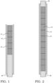
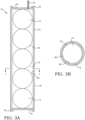
- the fuel rod may, include a cladding tube 12, open at both ends, and having an interior surface 38, and an exterior surface 42.
- An end plug 18, may be positioned to close the open bottom end of tube 12.
- the fissile material may be in the form of fuel pellets.
- Fissile material in the form of spheres 14 which have outer surfaces 36 may be loaded into the interior of the tube 12.
- the tube 12 may be a thin walled (for example, from 0.125 to 0.762 millimeter thick) Zr alloy tube loaded with nuclear fuel pellets 14 in a known manner.
- the free spaces 16 between of each sphere 14 and between the spheres 14 and the interior surface 38 of the tube 12 define voids or gaps.
- the cladding tube 12 may be filled with cylindrical pellets 14' having chamfers 34 at the top and bottom edges of the pellet cylinder. Gaps 16 form in the areas between the chamfers 34 and cylindrical surfaces 36' of the pellets 14' and the interior surface 38 of the tube 12.
- the fuel pellets may be any configuration.
- fuel pellets are in the form of right circular cylinders, such as those shown as pellets 14' having chamfers 34 formed therein, and may further have dishes (not shown) formed in the ends of the cylinders 14'.
- the internal diameter of the tube 12 may be sized such that it is only slightly larger than the diameter of the fuel pellets 14 or 14', large enough to allow the pellets 14 or 14' to be placed in the tube 12 without damage to the pellets, but close enough in diameter to force the pellets to stack, one on top of the other, when placed in the tube 12.
- the internal diameter of the tube 12 may be 0.15 millimeters larger than the diameter of the pellets 14, 14', allowing an average gap of approximately 0.075 millimeters between the exterior surface 36 or 36' of the pellet 14, 14' at its closest point to the interior surface 38 of the tube 12.
- top and bottom ends 40 and the cladding tube 12 may be rolled or otherwise compressed onto the end plugs 18, 20, after which the end plugs 18, 20 may be sealed to the tube 12 by any suitable means, such as welding.
- the end plugs 18 and 20 may have the same diameter as the pellets 14, 14'.
- the method includes reducing, and preferably substantially reducing, and most preferably eliminating free space 16, such as gas gaps and gaseous pathways between the fuel material and the cladding tube 12 that holds the fissile material (see Figs. 8-9 ), coating the tube with a protective material 30 (see Figs. 10 and 12 ), and placing the coated tube 12 within an outer protective covering 22 (see Fig. 12 ).
- the fuel cladding tube 12 may be formed from a zirconium (Zr) alloy, preferably a thin-walled Zr alloy of about 0.125 to 0.762 millimeters wall thickness.
- the protective covering 22 may be formed from a ceramic composite, such as a silicon carbide (SiC) composite.
- the method may in general proceed by loading a tube 12 with fissile material 14 or 14', compressing the tube 12 around the fissile material 14, 14' to reduce the free space 16 between the fissile material 14, 14' and the interior 38 of the tube 12, closing at least one open end of the tube, e.g., a first end, with a first end plug 18 or 20, filling the tube 12 with gas to a desired pressure, and closing the other open end, e.g., a second end, with a second end plug 18 or 20.
- the desired pressure may be from 0 to 40 atmospheres.
- the method may proceed by loading a tube 12 with fissile material 14, closing the ends of the tube with end plugs 18, 20, wherein at least one end plug has a port therein to allow gas to escape during the compression step, compressing the tube 12 around the fissile material 14 to reduce the free space 16 between the fissile material 14 and the interior 38 of the tube 12, and filling the tube 12 with gas through a gas fill port 54 to a desired pressure.
- the method may include fabricating a thin-walled Zr alloy tube 12 to a length longer than needed for the finished fuel rod 10.
- a solid bar 48 may be inserted into one open end of the tube 12 to maintain the internal diameter of the tube 12.
- the tube 12 may then be loaded with fuel pellets 14 or 14'.
- a second solid bar 48 may be inserted into the remaining open end of the tube 12.
- the fuel-loaded tube 12 may be placed in an isostatic press to compress the tube 12 around the fuel pellets 14, 14' to reduce or substantially if not completely eliminate free space 16 within the tube 12 around the pellets 14, 14'.
- the pellet-loaded cladding tube 12 may, in various aspects, be compressed onto the pellets 14, 14' until the interior surface 38 of tube 12 is in contact with the surfaces 36, 36' of pellets 14 or 14', respectively.
- this step may be performed by putting the pellet-loaded cladding tubes 12 into a high pressure chamber 52, and pressurizing the chamber using a high pressure fluid, such as water, other liquids, or compressed gas in a plenum 56 defined between the inside of the chamber 52 and either the tube 12 in a wet bag cold isostatic press 50 or a flexible liner membrane 64 in a dry bag cold isostatic press 60.
- a high pressure fluid such as water, other liquids, or compressed gas in a plenum 56 defined between the inside of the chamber 52 and either the tube 12 in a wet bag cold isostatic press 50 or a flexible liner membrane 64 in a dry bag cold isostatic press 60.
- the step may be performed mechanically by applying inward pressure circumferentially using a bladder or roller around some or all of the tube 12 to compress all of the exterior surface 42 of the metal alloy tube 12 simultaneously or in stages, taking care to avoid damage to the pellets 14 in the interior of the tube 12.
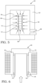
- FIG. 5 An exemplary wet bag cold isostatic press 50 is illustrated in Fig. 5 and an exemplary dry bag cold isostatic press 60 is illustrated in Fig. 6 .
- Both presses 50 and 60 include a chamber 52, a plenum 56 for filling with a pressurized fluid, such as a liquid or a gas, and an inlet port 68 (not shown in Fig. 6 ).
- the wet bag press 50 holds the fuel-loaded tube 12 in the plenum 56. Stoppers 66 are placed on each open end of the tube 12 if the tube has not been previously closed on one or both ends with an end plug 18, 20.
- Pressurized fluid fills the plenum 56 and pressure (indicated by force lines 62) is applied against the outside of the tube 12 sufficient to compress the tube 12 against the fuel pellets 14 or 14' to reduce or substantially if not completely eliminate free space 16 within the tube 12 around the pellets 14, 14'.
- the dry bag press 60 receives the fuel-loaded tube 12 into a space defined within a flexible liner 64.
- the flexible liner 64 expands and applies pressure against the outside of the tube 12 sufficient to compress the tube 12 against the fuel pellets 14 or 14' to reduce or substantially if not completely eliminate free space 16 within the tube 12 around the pellets 14, 14'.
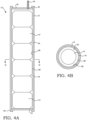
- Figs. 8 and 9 illustrate tubes 12 after being compressed. Depending on the configuration of the pellets 14, 14', the free space 16 is reduced or substantially reduced. Those skilled in the art will recognize that however small, some free space will remain in tube 12. That space will be filled with a gas.
- the tube 12 may be filled with gas to the desired pressure, followed by closing the open end or ends of the tube 12 with end plugs 18, 20.
- the tube 12 may alternatively, or additionally, be filled with gas through a gas fill port 54 in one or both end plugs 18, 20, after the open ends of tube 12 are closed.
- the gas in various aspects is a gas with good heat transfer properties, such as He or H 2 gas.
- a plenum spring 72 may be placed in one end, such as the top end, of the tube 12 before the top end plug 20 is welded in place.
- One or both of the end plugs 18, 20 may have a gas fill port 54.
- a gas, such as helium or hydrogen is introduced into the tube 12 through the gas fill port 54.
- the compressed tube 12 may be, in various embodiments, coated with a protective coating 30, such as a corrosion resistant layer.
- a protective coating 30 such as a corrosion resistant layer.
- the coating may be applied using a thermal process, such as a cold spray process.
- the corrosion resistant layer may be comprised of a dual layer that may include an interlayer and an outer layer.
- the corrosion resistant layer may comprise a single layer.
- Application of the corrosion resistant layer 30 on the exterior surface of the compressed tube 12 may, for example, include forming on the exterior of the compressed cladding tube 12 an interlayer with particles, preferably transition metal particles, such as molybdenum (Mo), niobium (Nb), tantalum (Ta), tungsten (W) and other particles, each particle having a diameter of 100 micrometer or less; and then forming an outer layer on the interlayer with particles selected from the group consisting of Cr, a Cr alloy, and combinations thereof.
- the outer layer particles may have a diameter of 100 micrometer or less.
- the corrosion resistant layer may be a single layer formed from particles selected from the group consisting of Cr, a Cr alloy, and combinations thereof.
- the corrosion resistant layer particles or outer layer particles are chromium-based alloys
- they may comprise 80 to 99 atom% of chromium.
- the chromium-based alloy may include at least one element selected from the group consisting of silicon, yttrium, aluminum, titanium, niobium, zirconium, and transition metal elements, at a combined content of 0.1 to 20 atomic %.
- the Cr alloy may be FeCrAlY.
- the method may further include heating a pressurized carrier gas to a temperature between 200 °C and 1000 °C; adding the interlayer particles to the heated carrier gas; and spraying the carrier gas and entrained particles at a velocity of 800 to 4000 ft./sec. (about 243.84 to 1219.20 meters/sec.) onto the cladding tube 12.
- the method may further include heating a pressurized carrier gas to a temperature between 200 °C and 1000 °C; adding the Cr or Cr alloy particles to the heated carrier gas; and spraying the carrier gas and entrained Cr or Cr alloy particles at a velocity of 800 to 4000 ft./sec. (about 243.84 to 1219.20 meters/sec.) onto the interlayer.
- the carrier gas is advantageously selected from inert and unreactive gases.
- the carrier gas may be selected from the group consisting of nitrogen, hydrogen, argon, carbon dioxide, helium, and combinations thereof.
- the carrier gas may be heated at a pressure up to 5.0 MPa.
- the carrier gas and particles are preferably sprayed continuously at very high rates until the desired coating thickness is reached.
- the coating thickness may, for example, be between 5 and 100 micrometer, but greater thicknesses of, for example, several hundred micrometer, may be deposited or lesser thicknesses of, for example, .5 to 1 micrometer, may be deposited.
- One or both layers may be applied using a thermal deposition process.
- the process may be conducted in an assembly such as that shown in Fig. 5 .
- a cold spray assembly 100 is shown.
- Assembly 100 includes a heater 120, a powder or particle hopper 140, a gun 160, nozzle 180 and delivery conduits 340, 260, 320 and 280.
- High pressure gas enters conduit 340 for delivery to heater 120, where heating occurs quickly; substantially instantaneously.
- the gas is directed through conduit 260 to gun 160.
- Particles held in hopper 140 are released and directed to gun 160 through conduit 280 where they are forced through nozzle 180 towards the exterior surface 42 of tube 12 by the pressurized gas jet 200.
- the sprayed particles 360 are deposited onto the exterior surface 42 of tube 12 to form the interlayer portion of protective layer 30 comprised of particles 240.
- the interlayer material may be chosen from those materials having a eutectic melting point with the zirconium or zirconium alloys that is above 1400 °C and thermal expansion coefficients and elastic modulus coefficients compatible with the zirconium or zirconium alloy on which it is coated and the coating which is applied above it.
- the particles used to form the interlayer may be Mo, but alternatively Ta, W or Nb particles, all of which form eutectics with Zr or Zr alloys greater than 1400 °C, and in various aspects, greater than 1500 °C.
- the particles used to form the interlayer may be Mo particles. Mo particles (or any of the other suitable interlayer particles) are added to hopper 140. The interlayer particles become entrained in the carrier gas when brought together in gun 160. The nozzle 180 narrows to force the particles and gas together and to increase the velocity of the gas jet 200 exiting nozzle 180. The particles are sprayed onto the exterior surface 42 of tube 12 at a velocity sufficient to provide a compact, impervious, or substantially impervious layer. In various aspects the velocity of the jet spray may be from 800 to 4000 ft./sec. (about 243.84 to 1219.20 meters/sec.).
- the interlayer may be ground and polished before deposition of the outer, corrosion resistant layer, which can be ground and polished thereafter.
- the particles used for the outer or corrosion resistant layer may be pure metallic chromium particles that have an average diameter of less than 20 micrometer.
- average diameter as used herein, those skilled in the art will recognize that the particles may be both spherical and non-spherical so that the “diameter” will be the longest dimension of the regularly or irregularly shaped particles, and the average diameter means that there will be some variation in the largest dimension of any given particle above or below 20 micrometer, but the average of the longest dimension of all particles used in the coating are together, 20 micrometer or less.
- the chromium or chromium-based alloy particles are solid particles.
- the outer layer is applied.
- it is applied following the compression step in the absence of an interlayer deposition step.
- the outer layer or the single corrosion resistant layer, chromium or chromium alloy particles or a combination thereof are added to the hopper 140.
- the chromium or chromium alloy particles become entrained in the carrier gas when brought together in gun 160.
- the nozzle 180 narrows to force the particles and gas together and to increase the velocity of the gas jet 200 exiting nozzle 180.
- the particles are sprayed at a velocity sufficient to provide a compact, impervious, or substantially impervious, Cr and/or Cr-based alloy layers.
- the velocity of the jet spray may be from 800 to 4000 ft./sec. (about 243.84 to 1219.20 meters/sec.).
- the particles 240 are deposited onto the surface of the interlayer or directly onto the surface 42 of tube 12 in the absence of an interlayer, at a rate sufficient to provide the desired production rate of coated tubing 12, at a commercial or research level.
- the rate of particle deposition for either of the layers depends on the powder apparent density (i.e., the amount of powder vs. the air or empty space in a specific volume) and the mechanical powder feeder or hopper used to inject the powder particles into the gas stream. Those skilled in the art can readily calculate the rate of deposition based on the equipment used in the process, and can adjust the rate of deposition by altering the components that factor into the rate.
- the rate of particle deposition may be up to 1000 kg/hour. An acceptable rate is between 1 and 100 kg/hour, and between 10 and 100 kg/hour, but higher and lower rates, such as 1.5 kg/hour, have been successfully used.
- the cold spray process relies on the controlled expansion of the heated carrier gas to propel the particles onto the substrate.
- the particles impact the surface of tube 12 or a previous deposited layer and undergo plastic deformation through adiabatic shear. Subsequent particle impacts build up to form the coating 30.
- the particles may also be warmed to temperatures one-third to one-half the melting point of powder expressed in degrees Kelvin before entering the flowing carrier gas in order to promote deformation.
- the nozzle 180 is rastered (i.e., sprayed in a pattern in which an area is sprayed from side to side in lines from top to bottom) across the area to be coated or where material buildup is needed.
- the tube 12 may be rotated as the nozzle moves lengthwise across the tube surface.
- the nozzle traverse speed and tube rotation are in synchronized motion so that uniform coverage is achieved.
- the rate of rotation and speed of traverse can vary substantially as long as the movement is synchronized for uniform coverage.
- the tube 12 may require some surface preparation such as grinding or chemical cleaning to remove surface contamination to improve adherence and distribution of the coating.
- the coating may be polished or not, depending on the surface texture that is desired.
- the coated, pellet-filled compressed tube 12 is placed in a protective covering having a closed end.
- Figure 11 illustrates an exemplary cover 22 with closed bottom end 24.
- the composite cover 22 may be a preformed tube having an internal diameter only slightly larger than the external diameter of the coated compressed tube 12 to permit the tube 12 to be inserted within cover 22 without damage but to minimize gaps and pathways between the exterior of the coated compressed tube 12 and the inner surface of the cover 22.
- the coated compressed pellet filled tube 12 is inserted into the SiC pre-formed cover 22.
- the bottom end 24 of the SiC cover 22 is closed.
- the top end 26 of the SiC cover 22 may remain open or may be closed.
- the rotective covering may be made of a SiC matrix composite material and is formed using established manufacturing techniques.
- the SiC composite layer may be between 0.10 and 0.80 millimeters thick.
- the compressed pellet-loaded cladding tube 12 is inserted into the SiC cover 22 with the tolerance only large enough to allow loading or to allow for pellet swelling.
- SiC As the outer cover 22 of the fuel rod 10 and to use a metal protected by a corrosion resistant coating as the inner cladding tube 12.
- the outer SiC cover 22 does not need to be hermetically sealed since the inner cladding tube 12 provides that function. Sealing the end plugs 18, 20 is not an issue since the end plugs 18, 20 are welded onto the cladding tube 12.
- the SiC cover 22 supports the inner metal cladding tube 12 when the reactor pressure is low (e.g., outages and a loss of coolant accident or a long term station blackout resulting in reactor depressurization) and limits the surface area of the inner cladding tube 12 that would be exposed to steam or air at > 1200 °C (thereby preventing a temperature spike driven by the autocatalytic oxidation of the zirconium). It also has the advantage of preventing blow-out at 900 °C that the coated only tubes 12 would have.
- the improved method described herein is expected to result in a minimal overall gap 16 since the pellet/cladding gap 16 will have been eliminated or significantly reduced in size, and the cladding/cover gap 28 is minimal.
- the cladding/cover gap 28 can be minimal since relatively large forces can be applied to the loaded tube 12 as it is inserted into the SiC cover 22 since the cover 22 does not have to maintain 100% hermeticity but can be as low as 90%. Therefore, as the pellet-loaded tube 12 is inserted into the cover 22, any cracking that may potentially occur in the SiC cover 22 does not present a problem.
- the geometry of the end plugs 18, 20 on the inserted end can help guide the loaded tube 12 into the SiC cover 22 past the uneven surface features on the inner diameter of the SiC cover 22.
- the overall combined gaps 16 and 28 can therefore be sized as required by the need to minimize the forces exerted by the pellets 14, 14' as they swell during irradiation and push outward on the thin-walled metal cladding 12 and then onto the SiC outer cover 22.
- the function of the SiC cover 22 is to provide tensile strength to the composite.
- the tensile strength component is provided by the fibers which are not affected by the higher temperatures. Therefore, if lower SiC matrix composite densities result due to the use of higher infiltration and deposition temperatures, the lower composite density will not be an issue.
- the method described herein eliminates, or at least substantially reduces the size of the internal pellet/cladding gap 16 during manufacture of the fuel rod 10 by compressing the cladding around the stacked fuel pellets.
- a coating either in a single or dual layer, is applied to the metal cladding to cover the entire metal surface.
- higher SiC infiltration and deposition temperatures can be used in making the cover 22 to minimize SiC corrosion even if it results in somewhat lower SiC composite density.
- the overall thickness of the cladding tube 12 wall can be significantly less than the thickness of a 100% SiC tube with the same hermeticity and strength specifications.
- the improved method described herein will provide a SiC protective cover 22 that can hold the cladding tube 12 together and reduce corrosion to >1800 °C, far higher than other metal alloys and much greater than Zr alloys alone.
- the overall neutron cross-section of the tube 12 can be less than the current Zr alloy tubing alone since the wall thickness is supported by the SiC cover 22 and a much thinner wall can be used while the SiC cover 22 has a cross-section only 25% of that of Zr alloys.
Landscapes
- Engineering & Computer Science (AREA)
- Physics & Mathematics (AREA)
- Plasma & Fusion (AREA)
- General Engineering & Computer Science (AREA)
- High Energy & Nuclear Physics (AREA)
- Manufacturing & Machinery (AREA)
- Metallurgy (AREA)
- Other Surface Treatments For Metallic Materials (AREA)
- Monitoring And Testing Of Nuclear Reactors (AREA)
- Coating By Spraying Or Casting (AREA)
Claims (15)
- Verfahren zur Herstellung eines Brennstabs (10), umfassend:Beladen eines Rohrs (12) mit einem ersten offenen Ende (40) und einem zweiten offenen Ende (40) mit Kernbrennstoff (14,14');Komprimieren des brennstoffbeladenen Rohrs (12) um den Brennstoff herum, so dass freier Raum im Rohr (12) verringert wird;Verschließen mindestens des ersten offenen Endes (40) oder des zweiten offenen Endes (40) des Rohrs (12);Füllen des brennstoffbeladenen Rohrs (12) mit einem zur Wärmeübertragung geeigneten Gas undPlatzieren des komprimierten Rohrs (12) innerhalb einer äußeren vorgeformten Schutzhülle (22), so dass ein zwischen der äußeren vorgeformten Schutzhülle (22) und dem komprimierten Rohr (12) definierter Zwischenraum (28) so bemessen ist, dass Kräfte minimiert werden, die durch das Anschwellen des Kernbrennstoffs (14,14') während der Abstrahlung ausgeübt werden.
- Verfahren nach Anspruch 1, bei dem der Kernbrennstoff gestapelte Pellets (14, 14') eines spaltbaren Materials umfasst.
- Verfahren nach Anspruch 1 oder 2, das ferner umfasst, das erste offene Ende (40) und das zweite offene Ende (40) des Rohrs (12) jeweils mit einem ersten Endstopfen (18) bzw. einem zweiten Endstopfen (20) zu verschließen, wobei mindestens entweder der erste Endstopfen (18) oder der zweite Endstopfen (20) eine Gasöffnung (54) aufweist.
- Verfahren nach Anspruch 1 oder 2, bei dem das Komprimieren des Rohrs (12) umfasst, das Rohr (12) in einer Kammer (52) zu platzieren und die Kammer (52) mit einem Fluid unter Druck zu setzen, um eine ausreichende Kraft auf das Rohr (12) auszuüben, um das Rohr (12) gegen den im Rohr (12) befindlichen Brennstoff zu drücken.
- Verfahren nach Anspruch 4, wobei das Fluid eine Flüssigkeit oder ein komprimiertes Gas ist.
- Verfahren nach Anspruch 4, bei dem die Kammer (52) eine kaltisostatische Presse in Form einer kaltisostatischen Trockenpresse (60), bei der eine flexible Membran (64) das Fluid von dem Rohr (12) trennt, oder in Form einer kaltisostatischen Nasspresse (60) ist, bei der das Fluid das Rohr (12) berührt.
- Verfahren nach Anspruch 4, bei dem der nach innen gerichtete Druck mit einer Walze um mindestens einen Teil des Rohrs (12) herum angewendet wird.
- Verfahren nach Anspruch 1 oder 2, das ferner umfasst, eine korrosionsbeständige Beschichtung (30) auf das komprimierte Rohr (12) aufzubringen, bevor das komprimierte Rohr (12) mit der vorgeformten Schutzhülle (22) abgedeckt wird.
- Verfahren nach Anspruch 8, bei dem die korrosionsbeständige Beschichtung (30) durch ein thermisches Abscheideverfahren wie etwa ein Kaltgasspritzverfahren aufgebracht wird.
- Verfahren nach Anspruch 9, bei dem das thermische Abscheideverfahren ein Kaltgasspritzverfahren ist, das Folgendes umfasst:Erhitzen eines unter Druck stehenden Trägergases auf eine Temperatur zwischen 100°C und 1200°C;Zugabe von Teilchen zu dem erhitzten Trägergas undSprühen des Trägergases und mitgerissener Teilchen mit einer Geschwindigkeit von 243,84 bis 1219,20 m/s (800 bis 4000 ft/s).
- Verfahren nach Anspruch 10, bei dem das Trägergas aus der Gruppe ausgewählt ist, die aus Stickstoff (N2), Wasserstoff (H2), Argon (Ar), Kohlendioxid (CO2) und Helium (He) und Kombinationen daraus besteht.
- Verfahren nach Anspruch 10, bei dem die Teilchen aus der Gruppe ausgewählt sind, die aus Chrom, Chromlegierungen und Kombinationen daraus besteht.
- Verfahren nach Anspruch 8, bei dem die korrosionsbeständige Beschichtung (30) das Aufbringen einer Doppelschicht umfasst.
- Verfahren nach Anspruch 13, bei dem das Aufbringen der Doppelschicht das Aufbringen einer Zwischenschicht unter Verwendung des Kaltgasspritzverfahrens und das Aufbringen einer äußeren Schicht unter Verwendung des Kaltgasspritzverfahrens umfasst, wobei die zur Bildung der Zwischenschicht verwendeten Teilchen Übergangsmetallteilchen sind, die aus der Gruppe ausgewählt sind, welche aus Molybdän (Mo), Niob (Nb), Tantal (Ta), Wolfram (W) und Kombinationen daraus besteht, und die zur Bildung der äußeren Schicht verwendeten Teilchen aus der Gruppe ausgewählt sind, die aus Chrom, Chromlegierungen und Kombinationen daraus besteht.
- Verfahren nach Anspruch 1 oder 2, bei dem die vorgeformte Schutzhülle (22) aus einem SiC-Verbundwerkstoff hergestellt ist.
Applications Claiming Priority (2)
| Application Number | Priority Date | Filing Date | Title |
|---|---|---|---|
| US15/450,167 US11031145B2 (en) | 2017-03-06 | 2017-03-06 | Method of manufacturing a reinforced nuclear fuel cladding using an intermediate thermal deposition layer |
| PCT/US2018/019923 WO2018164882A1 (en) | 2017-03-06 | 2018-02-27 | Method of manufacturing a reinforced nuclear fuel cladding using an intermediate thermal deposition layer |
Publications (3)
| Publication Number | Publication Date |
|---|---|
| EP3593358A1 EP3593358A1 (de) | 2020-01-15 |
| EP3593358A4 EP3593358A4 (de) | 2021-03-10 |
| EP3593358B1 true EP3593358B1 (de) | 2023-06-14 |
Family
ID=63355894
Family Applications (1)
| Application Number | Title | Priority Date | Filing Date |
|---|---|---|---|
| EP18763315.1A Active EP3593358B1 (de) | 2017-03-06 | 2018-02-27 | Verfahren zur herstellung einer verstärkten kernbrennstoffmantelung mit verwendung einer zwischenwärmeabscheidungsschicht |
Country Status (6)
| Country | Link |
|---|---|
| US (1) | US11031145B2 (de) |
| EP (1) | EP3593358B1 (de) |
| JP (1) | JP6963022B2 (de) |
| KR (1) | KR102553004B1 (de) |
| ES (1) | ES2952102T3 (de) |
| WO (1) | WO2018164882A1 (de) |
Families Citing this family (7)
| Publication number | Priority date | Publication date | Assignee | Title |
|---|---|---|---|---|
| US9335296B2 (en) | 2012-10-10 | 2016-05-10 | Westinghouse Electric Company Llc | Systems and methods for steam generator tube analysis for detection of tube degradation |
| US11935662B2 (en) | 2019-07-02 | 2024-03-19 | Westinghouse Electric Company Llc | Elongate SiC fuel elements |
| KR102523509B1 (ko) | 2019-09-19 | 2023-04-18 | 웨스팅하우스 일렉트릭 컴퍼니 엘엘씨 | 콜드 스프레이 침착물의 현장 접착 테스트를 수행하기 위한 장치 및 사용 방법 |
| CN112750538A (zh) * | 2020-12-31 | 2021-05-04 | 中核北方核燃料元件有限公司 | 一种碳化硅复合材料增强锆包壳管 |
| CN114438493A (zh) * | 2021-11-08 | 2022-05-06 | 上海核工程研究设计院有限公司 | 一种核电厂锆合金包壳管表面用抗高温水蒸气腐蚀涂层及其制备方法 |
| US20240145104A1 (en) * | 2022-11-02 | 2024-05-02 | Westinghouse Electric Company Llc | Use of oxidation resistant coatings to increase thin walled cladding tensile strength to increase uranium loadings |
| FR3154225A1 (fr) * | 2023-10-16 | 2025-04-18 | Framatome | Gaine de crayon de combustible nucléaire et procédé de fabrication d’une telle gaine |
Family Cites Families (37)
| Publication number | Priority date | Publication date | Assignee | Title |
|---|---|---|---|---|
| US2941933A (en) | 1959-11-30 | 1960-06-21 | William E Roake | Fuel element for nuclear reactor |
| US3088893A (en) * | 1960-08-31 | 1963-05-07 | Gen Electric | Malleable tube-clad article and manufacturing method therefor |
| US3427222A (en) | 1965-10-15 | 1969-02-11 | Westinghouse Electric Corp | Nuclear fuel elements |
| US4436677A (en) * | 1982-08-02 | 1984-03-13 | Westinghouse Electric Corp. | Nuclear fuel fabrication process |
| JPS59185692U (ja) * | 1983-05-30 | 1984-12-10 | 株式会社東芝 | 核燃料要素 |
| US4865804A (en) * | 1984-05-02 | 1989-09-12 | Westinghouse Electric Corp. | Fuel rod end plug |
| US4925619A (en) * | 1989-05-18 | 1990-05-15 | Westinghouse Electric Corp. | Rod pressurization sensing apparatus |
| US4971753A (en) * | 1989-06-23 | 1990-11-20 | General Electric Company | Nuclear fuel element, and method of forming same |
| US5075075A (en) | 1990-01-16 | 1991-12-24 | Westinghouse Electric Corp. | Nuclear reactor core having nuclear fuel and composite burnable absorber arranged for power peaking and moderator temperature coefficient control |
| WO1991019016A1 (fr) | 1990-05-19 | 1991-12-12 | Institut Teoreticheskoi I Prikladnoi Mekhaniki Sibirskogo Otdelenia Akademii Nauk Sssr | Procede et dispositif de revetement |
| US5182077A (en) | 1991-04-15 | 1993-01-26 | Gamma Engineering Corporation | Water cooled nuclear reactor and fuel elements therefor |
| US5236021A (en) * | 1991-12-23 | 1993-08-17 | General Electric Company | Powder filling apparatus |
| JP2642573B2 (ja) | 1991-12-27 | 1997-08-20 | 日本碍子株式会社 | SiC質焼結体 |
| JPH07508703A (ja) | 1992-06-12 | 1995-09-28 | ミネソタ・マイニング・アンド・マニュファクチュアリング・カンパニー | モノリシックセラミック/繊維強化セラミック複合材料 |
| US5517540A (en) | 1993-07-14 | 1996-05-14 | General Electric Company | Two-step process for bonding the elements of a three-layer cladding tube |
| US5490969A (en) | 1994-06-30 | 1996-02-13 | General Electric Company | Mould for isostatic pressing |
| JP3143086B2 (ja) | 1997-10-14 | 2001-03-07 | 核燃料サイクル開発機構 | SiC複合材料スリーブおよびその製造方法 |
| WO2000026921A2 (en) * | 1998-11-04 | 2000-05-11 | Reynolds Metals Company | Rodlet absorbing members for use with spent fuel |
| DE10224780A1 (de) * | 2002-06-04 | 2003-12-18 | Linde Ag | Verfahren und Vorrichtung zum Kaltgasspritzen |
| FR2853759B1 (fr) * | 2003-04-09 | 2005-05-13 | Commissariat Energie Atomique | Combustible nucleaire a fils tresses et son procede de realisation |
| US20060039524A1 (en) | 2004-06-07 | 2006-02-23 | Herbert Feinroth | Multi-layered ceramic tube for fuel containment barrier and other applications in nuclear and fossil power plants |
| US7139360B2 (en) | 2004-10-14 | 2006-11-21 | Westinghouse Electric Co. Llc | Use of boron or enriched boron 10 in UO2 |
| US7700202B2 (en) | 2006-02-16 | 2010-04-20 | Alliant Techsystems Inc. | Precursor formulation of a silicon carbide material |
| RU2305334C1 (ru) * | 2006-03-15 | 2007-08-27 | Федеральное государственное унитарное предприятие Научно-исследовательский институт Научно-производственное объединение "Луч" | Способ изготовления керметного стержня топливного сердечника тепловыделяющего элемента ядерного реактора |
| US7815964B2 (en) | 2007-03-29 | 2010-10-19 | Westinghouse Electric Co Llc | Method of applying a burnable poison onto the exterior of nuclear rod cladding |
| US8085894B2 (en) * | 2007-04-23 | 2011-12-27 | Lawrence Livermore National Security, Llc | Swelling-resistant nuclear fuel |
| US8792607B2 (en) | 2008-10-14 | 2014-07-29 | General Electric Company | Fuel rod assembly and method for mitigating the radiation-enhanced corrosion of a zirconium-based component |
| FR2966760B1 (fr) * | 2010-10-29 | 2012-12-21 | Areva Nc | Dispositif de maintien axial et de mise en rotation autour de son axe d'un element de forme allongee |
| US20120314831A1 (en) * | 2011-06-10 | 2012-12-13 | Ut-Battelle, Llc | Light Water Reactor TRISO Particle-Metal-Matrix Composite Fuel |
| FR2989923B1 (fr) | 2012-04-26 | 2014-05-16 | Commissariat Energie Atomique | Materiau multicouche resistant a l'oxydation en milieu nucleaire. |
| KR101405396B1 (ko) | 2012-06-25 | 2014-06-10 | 한국수력원자력 주식회사 | 표면에 혼합층을 포함하는 코팅층이 형성된 지르코늄 합금 및 이의 제조방법 |
| US8971476B2 (en) | 2012-11-07 | 2015-03-03 | Westinghouse Electric Company Llc | Deposition of integrated protective material into zirconium cladding for nuclear reactors by high-velocity thermal application |
| US9911511B2 (en) | 2012-12-28 | 2018-03-06 | Global Nuclear Fuel—Americas, LLC | Fuel rods with wear-inhibiting coatings and methods of making the same |
| US9455053B2 (en) * | 2013-09-16 | 2016-09-27 | Westinghouse Electric Company Llc | SiC matrix fuel cladding tube with spark plasma sintered end plugs |
| US10593434B2 (en) * | 2014-03-12 | 2020-03-17 | Westinghouse Electric Company Llc | Ceramic reinforced zirconium alloy nuclear fuel cladding with intermediate oxidation resistant layer |
| US9721676B2 (en) | 2014-05-27 | 2017-08-01 | Westinghouse Electric Company, Llc | Deposition of a protective coating including metal-containing and chromium-containing layers on zirconium alloy for nuclear power applications |
| KR101595436B1 (ko) * | 2014-09-23 | 2016-02-19 | 한국원자력연구원 | 다층구조 핵연료 피복관 및 이의 제조방법 |
-
2017
- 2017-03-06 US US15/450,167 patent/US11031145B2/en active Active
-
2018
- 2018-02-27 KR KR1020197028231A patent/KR102553004B1/ko active Active
- 2018-02-27 ES ES18763315T patent/ES2952102T3/es active Active
- 2018-02-27 WO PCT/US2018/019923 patent/WO2018164882A1/en not_active Ceased
- 2018-02-27 JP JP2019547480A patent/JP6963022B2/ja active Active
- 2018-02-27 EP EP18763315.1A patent/EP3593358B1/de active Active
Also Published As
| Publication number | Publication date |
|---|---|
| WO2018164882A1 (en) | 2018-09-13 |
| EP3593358A4 (de) | 2021-03-10 |
| US11031145B2 (en) | 2021-06-08 |
| US20180254114A1 (en) | 2018-09-06 |
| EP3593358A1 (de) | 2020-01-15 |
| KR20190117748A (ko) | 2019-10-16 |
| JP2020509384A (ja) | 2020-03-26 |
| ES2952102T3 (es) | 2023-10-27 |
| JP6963022B2 (ja) | 2021-11-05 |
| KR102553004B1 (ko) | 2023-07-06 |
Similar Documents
| Publication | Publication Date | Title |
|---|---|---|
| EP3593358B1 (de) | Verfahren zur herstellung einer verstärkten kernbrennstoffmantelung mit verwendung einer zwischenwärmeabscheidungsschicht | |
| KR102685314B1 (ko) | 실리콘 카바이드 강화 지르코늄계 클래딩 | |
| US6203752B1 (en) | Rhenium-coated tungsten-based alloy and composite articles and method therefor | |
| EP3117440B1 (de) | Doppelt abgedichteter brennstabendstopfen für keramikhaltige verkleidung | |
| EP3047489B1 (de) | Sic-matrix-brennstabhüllrohr mit spark-plasma-gesinterten endstopfen | |
| EP3010024B1 (de) | Rohrkörper und verfahren zur herstellung des rohrkörpers | |
| US9982350B2 (en) | Multilayer composite fuel clad system with high temperature hermeticity and accident tolerance | |
| EP3704714B1 (de) | Hochtemperatur-kernbrennstoffsystem für thermische neutronenreaktoren | |
| KR20140048995A (ko) | 세라믹 매트릭스 복합 재료로 만들어진 향상된 다층 튜브, 결과적인 핵연료 클래딩 및 관련된 제조 방법 | |
| EP3117439B1 (de) | Keramikverstärkte zirkoniumlegierungskernbrennelementverkleidung mit oxidationsbeständiger zwischenschicht | |
| WO2018017145A1 (en) | Spray methods for coating nuclear fuel rods to add corrosion resistant barrier | |
| WO2012129677A1 (en) | Ceramic encapsulations for nuclear materials and systems and methods of production and use | |
| JP7685652B2 (ja) | 軽水炉用高温制御棒 | |
| EP1005696B1 (de) | Verfahren zur herstellung eines kernbrennstabhüllrohres | |
| EP3596736A1 (de) | Beschichtete u3si2-pellets mit verbesserter wasser- und dampfoxidationsbeständigkeit | |
| WO2025007638A1 (zh) | 一种全致密三维纤维增韧钨基复合材料的制备方法 | |
| CN118881919A (zh) | 无内衬碳纤维全缠绕复合材料压力容器及其生产方法 | |
| HK40077592A (en) | Method for manufacturing a fuel rod cladding tube |
Legal Events
| Date | Code | Title | Description |
|---|---|---|---|
| STAA | Information on the status of an ep patent application or granted ep patent |
Free format text: STATUS: THE INTERNATIONAL PUBLICATION HAS BEEN MADE |
|
| PUAI | Public reference made under article 153(3) epc to a published international application that has entered the european phase |
Free format text: ORIGINAL CODE: 0009012 |
|
| STAA | Information on the status of an ep patent application or granted ep patent |
Free format text: STATUS: REQUEST FOR EXAMINATION WAS MADE |
|
| 17P | Request for examination filed |
Effective date: 20190918 |
|
| AK | Designated contracting states |
Kind code of ref document: A1 Designated state(s): AL AT BE BG CH CY CZ DE DK EE ES FI FR GB GR HR HU IE IS IT LI LT LU LV MC MK MT NL NO PL PT RO RS SE SI SK SM TR |
|
| AX | Request for extension of the european patent |
Extension state: BA ME |
|
| DAV | Request for validation of the european patent (deleted) | ||
| DAX | Request for extension of the european patent (deleted) | ||
| RIC1 | Information provided on ipc code assigned before grant |
Ipc: G21C 3/20 20060101ALI20201109BHEP Ipc: G21C 3/10 20060101ALI20201109BHEP Ipc: G21C 3/07 20060101AFI20201109BHEP Ipc: G21C 21/06 20060101ALI20201109BHEP Ipc: G21C 3/06 20060101ALI20201109BHEP |
|
| REG | Reference to a national code |
Ref country code: DE Ref legal event code: R079 Free format text: PREVIOUS MAIN CLASS: G21C0003060000 Ipc: G21C0003070000 Ref document number: 602018051863 Country of ref document: DE |
|
| A4 | Supplementary search report drawn up and despatched |
Effective date: 20210210 |
|
| RIC1 | Information provided on ipc code assigned before grant |
Ipc: G21C 3/10 20060101ALI20210204BHEP Ipc: G21C 3/20 20060101ALI20210204BHEP Ipc: G21C 3/06 20060101ALI20210204BHEP Ipc: G21C 21/06 20060101ALI20210204BHEP Ipc: G21C 3/07 20060101AFI20210204BHEP |
|
| GRAP | Despatch of communication of intention to grant a patent |
Free format text: ORIGINAL CODE: EPIDOSNIGR1 |
|
| STAA | Information on the status of an ep patent application or granted ep patent |
Free format text: STATUS: GRANT OF PATENT IS INTENDED |
|
| INTG | Intention to grant announced |
Effective date: 20230103 |
|
| GRAS | Grant fee paid |
Free format text: ORIGINAL CODE: EPIDOSNIGR3 |
|
| GRAA | (expected) grant |
Free format text: ORIGINAL CODE: 0009210 |
|
| STAA | Information on the status of an ep patent application or granted ep patent |
Free format text: STATUS: THE PATENT HAS BEEN GRANTED |
|
| AK | Designated contracting states |
Kind code of ref document: B1 Designated state(s): AL AT BE BG CH CY CZ DE DK EE ES FI FR GB GR HR HU IE IS IT LI LT LU LV MC MK MT NL NO PL PT RO RS SE SI SK SM TR |
|
| REG | Reference to a national code |
Ref country code: CH Ref legal event code: EP |
|
| REG | Reference to a national code |
Ref country code: DE Ref legal event code: R096 Ref document number: 602018051863 Country of ref document: DE |
|
| REG | Reference to a national code |
Ref country code: AT Ref legal event code: REF Ref document number: 1579820 Country of ref document: AT Kind code of ref document: T Effective date: 20230715 |
|
| REG | Reference to a national code |
Ref country code: SE Ref legal event code: TRGR |
|
| REG | Reference to a national code |
Ref country code: LT Ref legal event code: MG9D |
|
| REG | Reference to a national code |
Ref country code: NL Ref legal event code: MP Effective date: 20230614 |
|
| REG | Reference to a national code |
Ref country code: ES Ref legal event code: FG2A Ref document number: 2952102 Country of ref document: ES Kind code of ref document: T3 Effective date: 20231027 |
|
| PG25 | Lapsed in a contracting state [announced via postgrant information from national office to epo] |
Ref country code: NO Free format text: LAPSE BECAUSE OF FAILURE TO SUBMIT A TRANSLATION OF THE DESCRIPTION OR TO PAY THE FEE WITHIN THE PRESCRIBED TIME-LIMIT Effective date: 20230914 |
|
| REG | Reference to a national code |
Ref country code: AT Ref legal event code: MK05 Ref document number: 1579820 Country of ref document: AT Kind code of ref document: T Effective date: 20230614 |
|
| PG25 | Lapsed in a contracting state [announced via postgrant information from national office to epo] |
Ref country code: RS Free format text: LAPSE BECAUSE OF FAILURE TO SUBMIT A TRANSLATION OF THE DESCRIPTION OR TO PAY THE FEE WITHIN THE PRESCRIBED TIME-LIMIT Effective date: 20230614 Ref country code: NL Free format text: LAPSE BECAUSE OF FAILURE TO SUBMIT A TRANSLATION OF THE DESCRIPTION OR TO PAY THE FEE WITHIN THE PRESCRIBED TIME-LIMIT Effective date: 20230614 Ref country code: LV Free format text: LAPSE BECAUSE OF FAILURE TO SUBMIT A TRANSLATION OF THE DESCRIPTION OR TO PAY THE FEE WITHIN THE PRESCRIBED TIME-LIMIT Effective date: 20230614 Ref country code: LT Free format text: LAPSE BECAUSE OF FAILURE TO SUBMIT A TRANSLATION OF THE DESCRIPTION OR TO PAY THE FEE WITHIN THE PRESCRIBED TIME-LIMIT Effective date: 20230614 Ref country code: HR Free format text: LAPSE BECAUSE OF FAILURE TO SUBMIT A TRANSLATION OF THE DESCRIPTION OR TO PAY THE FEE WITHIN THE PRESCRIBED TIME-LIMIT Effective date: 20230614 Ref country code: GR Free format text: LAPSE BECAUSE OF FAILURE TO SUBMIT A TRANSLATION OF THE DESCRIPTION OR TO PAY THE FEE WITHIN THE PRESCRIBED TIME-LIMIT Effective date: 20230915 |
|
| PG25 | Lapsed in a contracting state [announced via postgrant information from national office to epo] |
Ref country code: FI Free format text: LAPSE BECAUSE OF FAILURE TO SUBMIT A TRANSLATION OF THE DESCRIPTION OR TO PAY THE FEE WITHIN THE PRESCRIBED TIME-LIMIT Effective date: 20230614 |
|
| PG25 | Lapsed in a contracting state [announced via postgrant information from national office to epo] |
Ref country code: SK Free format text: LAPSE BECAUSE OF FAILURE TO SUBMIT A TRANSLATION OF THE DESCRIPTION OR TO PAY THE FEE WITHIN THE PRESCRIBED TIME-LIMIT Effective date: 20230614 |
|
| PG25 | Lapsed in a contracting state [announced via postgrant information from national office to epo] |
Ref country code: IS Free format text: LAPSE BECAUSE OF FAILURE TO SUBMIT A TRANSLATION OF THE DESCRIPTION OR TO PAY THE FEE WITHIN THE PRESCRIBED TIME-LIMIT Effective date: 20231014 |
|
| PG25 | Lapsed in a contracting state [announced via postgrant information from national office to epo] |
Ref country code: SM Free format text: LAPSE BECAUSE OF FAILURE TO SUBMIT A TRANSLATION OF THE DESCRIPTION OR TO PAY THE FEE WITHIN THE PRESCRIBED TIME-LIMIT Effective date: 20230614 Ref country code: SK Free format text: LAPSE BECAUSE OF FAILURE TO SUBMIT A TRANSLATION OF THE DESCRIPTION OR TO PAY THE FEE WITHIN THE PRESCRIBED TIME-LIMIT Effective date: 20230614 Ref country code: RO Free format text: LAPSE BECAUSE OF FAILURE TO SUBMIT A TRANSLATION OF THE DESCRIPTION OR TO PAY THE FEE WITHIN THE PRESCRIBED TIME-LIMIT Effective date: 20230614 Ref country code: PT Free format text: LAPSE BECAUSE OF FAILURE TO SUBMIT A TRANSLATION OF THE DESCRIPTION OR TO PAY THE FEE WITHIN THE PRESCRIBED TIME-LIMIT Effective date: 20231016 Ref country code: IS Free format text: LAPSE BECAUSE OF FAILURE TO SUBMIT A TRANSLATION OF THE DESCRIPTION OR TO PAY THE FEE WITHIN THE PRESCRIBED TIME-LIMIT Effective date: 20231014 Ref country code: EE Free format text: LAPSE BECAUSE OF FAILURE TO SUBMIT A TRANSLATION OF THE DESCRIPTION OR TO PAY THE FEE WITHIN THE PRESCRIBED TIME-LIMIT Effective date: 20230614 Ref country code: AT Free format text: LAPSE BECAUSE OF FAILURE TO SUBMIT A TRANSLATION OF THE DESCRIPTION OR TO PAY THE FEE WITHIN THE PRESCRIBED TIME-LIMIT Effective date: 20230614 |
|
| PG25 | Lapsed in a contracting state [announced via postgrant information from national office to epo] |
Ref country code: PL Free format text: LAPSE BECAUSE OF FAILURE TO SUBMIT A TRANSLATION OF THE DESCRIPTION OR TO PAY THE FEE WITHIN THE PRESCRIBED TIME-LIMIT Effective date: 20230614 |
|
| REG | Reference to a national code |
Ref country code: DE Ref legal event code: R097 Ref document number: 602018051863 Country of ref document: DE |
|
| PLBE | No opposition filed within time limit |
Free format text: ORIGINAL CODE: 0009261 |
|
| STAA | Information on the status of an ep patent application or granted ep patent |
Free format text: STATUS: NO OPPOSITION FILED WITHIN TIME LIMIT |
|
| PG25 | Lapsed in a contracting state [announced via postgrant information from national office to epo] |
Ref country code: DK Free format text: LAPSE BECAUSE OF FAILURE TO SUBMIT A TRANSLATION OF THE DESCRIPTION OR TO PAY THE FEE WITHIN THE PRESCRIBED TIME-LIMIT Effective date: 20230614 |
|
| PG25 | Lapsed in a contracting state [announced via postgrant information from national office to epo] |
Ref country code: SI Free format text: LAPSE BECAUSE OF FAILURE TO SUBMIT A TRANSLATION OF THE DESCRIPTION OR TO PAY THE FEE WITHIN THE PRESCRIBED TIME-LIMIT Effective date: 20230614 |
|
| 26N | No opposition filed |
Effective date: 20240315 |
|
| PG25 | Lapsed in a contracting state [announced via postgrant information from national office to epo] |
Ref country code: SI Free format text: LAPSE BECAUSE OF FAILURE TO SUBMIT A TRANSLATION OF THE DESCRIPTION OR TO PAY THE FEE WITHIN THE PRESCRIBED TIME-LIMIT Effective date: 20230614 Ref country code: IT Free format text: LAPSE BECAUSE OF FAILURE TO SUBMIT A TRANSLATION OF THE DESCRIPTION OR TO PAY THE FEE WITHIN THE PRESCRIBED TIME-LIMIT Effective date: 20230614 |
|
| PG25 | Lapsed in a contracting state [announced via postgrant information from national office to epo] |
Ref country code: MC Free format text: LAPSE BECAUSE OF FAILURE TO SUBMIT A TRANSLATION OF THE DESCRIPTION OR TO PAY THE FEE WITHIN THE PRESCRIBED TIME-LIMIT Effective date: 20230614 |
|
| REG | Reference to a national code |
Ref country code: CH Ref legal event code: PL |
|
| PG25 | Lapsed in a contracting state [announced via postgrant information from national office to epo] |
Ref country code: LU Free format text: LAPSE BECAUSE OF NON-PAYMENT OF DUE FEES Effective date: 20240227 |
|
| PG25 | Lapsed in a contracting state [announced via postgrant information from national office to epo] |
Ref country code: CH Free format text: LAPSE BECAUSE OF NON-PAYMENT OF DUE FEES Effective date: 20240229 |
|
| PG25 | Lapsed in a contracting state [announced via postgrant information from national office to epo] |
Ref country code: LU Free format text: LAPSE BECAUSE OF NON-PAYMENT OF DUE FEES Effective date: 20240227 Ref country code: CH Free format text: LAPSE BECAUSE OF NON-PAYMENT OF DUE FEES Effective date: 20240229 |
|
| PG25 | Lapsed in a contracting state [announced via postgrant information from national office to epo] |
Ref country code: BG Free format text: LAPSE BECAUSE OF FAILURE TO SUBMIT A TRANSLATION OF THE DESCRIPTION OR TO PAY THE FEE WITHIN THE PRESCRIBED TIME-LIMIT Effective date: 20230614 |
|
| PG25 | Lapsed in a contracting state [announced via postgrant information from national office to epo] |
Ref country code: BG Free format text: LAPSE BECAUSE OF FAILURE TO SUBMIT A TRANSLATION OF THE DESCRIPTION OR TO PAY THE FEE WITHIN THE PRESCRIBED TIME-LIMIT Effective date: 20230614 |
|
| PG25 | Lapsed in a contracting state [announced via postgrant information from national office to epo] |
Ref country code: IE Free format text: LAPSE BECAUSE OF NON-PAYMENT OF DUE FEES Effective date: 20240227 |
|
| PG25 | Lapsed in a contracting state [announced via postgrant information from national office to epo] |
Ref country code: IE Free format text: LAPSE BECAUSE OF NON-PAYMENT OF DUE FEES Effective date: 20240227 |
|
| PGFP | Annual fee paid to national office [announced via postgrant information from national office to epo] |
Ref country code: DE Payment date: 20250226 Year of fee payment: 8 |
|
| PGFP | Annual fee paid to national office [announced via postgrant information from national office to epo] |
Ref country code: ES Payment date: 20250311 Year of fee payment: 8 |
|
| PGFP | Annual fee paid to national office [announced via postgrant information from national office to epo] |
Ref country code: SE Payment date: 20250224 Year of fee payment: 8 |
|
| PGFP | Annual fee paid to national office [announced via postgrant information from national office to epo] |
Ref country code: BE Payment date: 20250227 Year of fee payment: 8 |
|
| PGFP | Annual fee paid to national office [announced via postgrant information from national office to epo] |
Ref country code: FR Payment date: 20250225 Year of fee payment: 8 Ref country code: CZ Payment date: 20250224 Year of fee payment: 8 |
|
| PGFP | Annual fee paid to national office [announced via postgrant information from national office to epo] |
Ref country code: GB Payment date: 20250228 Year of fee payment: 8 |
|
| PG25 | Lapsed in a contracting state [announced via postgrant information from national office to epo] |
Ref country code: CY Free format text: LAPSE BECAUSE OF FAILURE TO SUBMIT A TRANSLATION OF THE DESCRIPTION OR TO PAY THE FEE WITHIN THE PRESCRIBED TIME-LIMIT; INVALID AB INITIO Effective date: 20180227 |
|
| PG25 | Lapsed in a contracting state [announced via postgrant information from national office to epo] |
Ref country code: HU Free format text: LAPSE BECAUSE OF FAILURE TO SUBMIT A TRANSLATION OF THE DESCRIPTION OR TO PAY THE FEE WITHIN THE PRESCRIBED TIME-LIMIT; INVALID AB INITIO Effective date: 20180227 |
|
| PG25 | Lapsed in a contracting state [announced via postgrant information from national office to epo] |
Ref country code: TR Free format text: LAPSE BECAUSE OF FAILURE TO SUBMIT A TRANSLATION OF THE DESCRIPTION OR TO PAY THE FEE WITHIN THE PRESCRIBED TIME-LIMIT Effective date: 20230614 |