EP3704714B1 - Hochtemperatur-kernbrennstoffsystem für thermische neutronenreaktoren - Google Patents
Hochtemperatur-kernbrennstoffsystem für thermische neutronenreaktoren Download PDFInfo
- Publication number
- EP3704714B1 EP3704714B1 EP18892438.5A EP18892438A EP3704714B1 EP 3704714 B1 EP3704714 B1 EP 3704714B1 EP 18892438 A EP18892438 A EP 18892438A EP 3704714 B1 EP3704714 B1 EP 3704714B1
- Authority
- EP
- European Patent Office
- Prior art keywords
- fuel
- recited
- fuel rod
- cladding
- coating
- Prior art date
- Legal status (The legal status is an assumption and is not a legal conclusion. Google has not performed a legal analysis and makes no representation as to the accuracy of the status listed.)
- Active
Links
Images



Classifications
-
- G—PHYSICS
- G21—NUCLEAR PHYSICS; NUCLEAR ENGINEERING
- G21C—NUCLEAR REACTORS
- G21C3/00—Reactor fuel elements and their assemblies; Selection of substances for use as reactor fuel elements
- G21C3/42—Selection of substances for use as reactor fuel
- G21C3/58—Solid reactor fuel Pellets made of fissile material
- G21C3/60—Metallic fuel; Intermetallic dispersions
-
- G—PHYSICS
- G21—NUCLEAR PHYSICS; NUCLEAR ENGINEERING
- G21C—NUCLEAR REACTORS
- G21C3/00—Reactor fuel elements and their assemblies; Selection of substances for use as reactor fuel elements
- G21C3/02—Fuel elements
- G21C3/04—Constructional details
- G21C3/06—Casings; Jackets
- G21C3/07—Casings; Jackets characterised by their material, e.g. alloys
-
- G—PHYSICS
- G21—NUCLEAR PHYSICS; NUCLEAR ENGINEERING
- G21C—NUCLEAR REACTORS
- G21C1/00—Reactor types
- G21C1/04—Thermal reactors ; Epithermal reactors
-
- G—PHYSICS
- G21—NUCLEAR PHYSICS; NUCLEAR ENGINEERING
- G21C—NUCLEAR REACTORS
- G21C21/00—Apparatus or processes specially adapted to the manufacture of reactors or parts thereof
- G21C21/02—Manufacture of fuel elements or breeder elements contained in non-active casings
-
- G—PHYSICS
- G21—NUCLEAR PHYSICS; NUCLEAR ENGINEERING
- G21C—NUCLEAR REACTORS
- G21C3/00—Reactor fuel elements and their assemblies; Selection of substances for use as reactor fuel elements
- G21C3/02—Fuel elements
- G21C3/04—Constructional details
- G21C3/045—Pellets
-
- G—PHYSICS
- G21—NUCLEAR PHYSICS; NUCLEAR ENGINEERING
- G21C—NUCLEAR REACTORS
- G21C3/00—Reactor fuel elements and their assemblies; Selection of substances for use as reactor fuel elements
- G21C3/02—Fuel elements
- G21C3/04—Constructional details
- G21C3/045—Pellets
- G21C3/047—Pellet-clad interaction
-
- G—PHYSICS
- G21—NUCLEAR PHYSICS; NUCLEAR ENGINEERING
- G21C—NUCLEAR REACTORS
- G21C3/00—Reactor fuel elements and their assemblies; Selection of substances for use as reactor fuel elements
- G21C3/02—Fuel elements
- G21C3/04—Constructional details
- G21C3/16—Details of the construction within the casing
- G21C3/20—Details of the construction within the casing with coating on fuel or on inside of casing; with non-active interlayer between casing and active material with multiple casings or multiple active layers
-
- G—PHYSICS
- G21—NUCLEAR PHYSICS; NUCLEAR ENGINEERING
- G21C—NUCLEAR REACTORS
- G21C3/00—Reactor fuel elements and their assemblies; Selection of substances for use as reactor fuel elements
- G21C3/42—Selection of substances for use as reactor fuel
- G21C3/58—Solid reactor fuel Pellets made of fissile material
- G21C3/62—Ceramic fuel
- G21C3/626—Coated fuel particles
-
- G—PHYSICS
- G21—NUCLEAR PHYSICS; NUCLEAR ENGINEERING
- G21C—NUCLEAR REACTORS
- G21C7/00—Control of nuclear reaction
- G21C7/02—Control of nuclear reaction by using self-regulating properties of reactor materials, e.g. Doppler effect
- G21C7/04—Control of nuclear reaction by using self-regulating properties of reactor materials, e.g. Doppler effect of burnable poisons
-
- G—PHYSICS
- G21—NUCLEAR PHYSICS; NUCLEAR ENGINEERING
- G21C—NUCLEAR REACTORS
- G21C9/00—Emergency protection arrangements structurally associated with the reactor, e.g. safety valves provided with pressure equalisation devices
- G21C9/02—Means for effecting very rapid reduction of the reactivity factor under fault conditions, e.g. reactor fuse; Control elements having arrangements activated in an emergency
- G21C9/033—Means for effecting very rapid reduction of the reactivity factor under fault conditions, e.g. reactor fuse; Control elements having arrangements activated in an emergency by an absorbent fluid
-
- Y—GENERAL TAGGING OF NEW TECHNOLOGICAL DEVELOPMENTS; GENERAL TAGGING OF CROSS-SECTIONAL TECHNOLOGIES SPANNING OVER SEVERAL SECTIONS OF THE IPC; TECHNICAL SUBJECTS COVERED BY FORMER USPC CROSS-REFERENCE ART COLLECTIONS [XRACs] AND DIGESTS
- Y02—TECHNOLOGIES OR APPLICATIONS FOR MITIGATION OR ADAPTATION AGAINST CLIMATE CHANGE
- Y02E—REDUCTION OF GREENHOUSE GAS [GHG] EMISSIONS, RELATED TO ENERGY GENERATION, TRANSMISSION OR DISTRIBUTION
- Y02E30/00—Energy generation of nuclear origin
- Y02E30/30—Nuclear fission reactors
Definitions
- the invention relates to nuclear fuel, and more specifically to an accident tolerant fuel for use in light and heavy water reactors.
- Fissile material for use as nuclear fuel includes uranium dioxide (UO 2 ), plutonium dioxide (PuO 2 ), uranium nitride (UN) either with natural nitrogen or nitrogen enriched in the 15 N isotope, and/or tri-uranium disilicide (U 3 Si 2 ), typically in pellet form.
- Fuel rods are encased in a cladding that acts as a containment for the fissile material.
- the cladding is preferably in the form of an elongate structure, such as a tube, and the fuel rod includes a plurality of pellets stacked in the cladding tube.
- a typical fuel rod In a typical fuel rod, the top and bottom ends of the rod are closed with end caps and a spring or other device to bias the fuel pellets together in the stack is positioned within the cladding on one end of the fuel rod.
- fuel rods In a reactor, fuel rods are grouped together in an array which is organized to provide a neutron flux in the core sufficient to support a high rate of nuclear fission and the release of a large amount of energy in the form of heat.
- UO 2 is currently a widely used nuclear fuel. Although susceptible to water and steam oxidation, U 3 Si 2 is the favored fuel material for accident tolerant fuel (ATF) systems. U 3 Si 2 has a high density (12.2 gm/cm 3 ), very high thermal conductivity (up to 5x UO 2 ), and a melting point of 1665 °C. To date, however, its use has been confined to lead test rods in test reactors where it is buried in a thick aluminum cladding which makes water coolant exposure unlikely, and where integral fuel burnable absorbers (IFBA) are not a required component of the fuel.
- IFBA integral fuel burnable absorbers
- nuclear fuel components are designed for accidents that can result in fuel temperatures of about 1700 °C assuming the addition of a minimal amount of a coolant in the fuel assembly.
- Nuclear fuels have been combined with a coated zirconium alloy cladding. Due to the ability of the coated zirconium to expand with the expanding pellet during the useful life of the fissile material, the gap between the pellet and the cladding, which is a major source of thermal heat transfer resistance, can be small, keeping the centerline temperature below the melting point under all transient conditions.
- the relatively low melting point of U 3 Si 2 is therefore not an issue because the very high thermal conductivity of U 3 Si 2 precludes fuel centerline melt issues during unexpected power transients.
- metal cladding can react exothermally with steam at over 1093 °C.
- Zirconium cladding metals protecting the nuclear fuel may lose strength during "a loss of coolant" accident, where reactor temperatures can reach as high as 1204 °C, and expand due to internal fission gases within the fuel rod.
- the melting point of a mixture of two or more solids depends on the relative proportions of the ingredients.
- a low melting eutectic mixture forms when the solids are at such proportions that the melting point of the mixture is as low as possible.
- alloys used in situations where relatively low melting points can create unintended problems, the formation of eutectic mixtures is ideally avoided or the undesirable consequences of a eutectic mixture formation is ideally minimized.
- US 4 717 534 teaches a fuel rod including an intermediate cladding layer comprising zirconium alloy mixed with a boron-containing integral fuel burnable absorber.
- the fuel rod includes in various aspects, a nuclear fuel selected from the group consisting of U 3 Si 2 and UN, in pellet form, a boron-containing integral fuel burnable absorber intermixed with the nuclear fuel in the pellet, and a zirconium-containing cladding material for housing the integral fuel burnable absorber intermixed with the nuclear fuel in the pellet, the cladding material having a coating applied thereto.
- a nuclear fuel selected from the group consisting of U 3 Si 2 and UN, in pellet form, a boron-containing integral fuel burnable absorber intermixed with the nuclear fuel in the pellet, and a zirconium-containing cladding material for housing the integral fuel burnable absorber intermixed with the nuclear fuel in the pellet, the cladding material having a coating applied thereto.
- the interlayer may be applied to the exterior surface of the cladding material by a hot spray process, such as a plasma arc process, or by a cold spray process.
- the coating may have a thickness of 5 to 50 microns, and may be applied to the cladding material, or to the interlayer in those embodiments where an interlayer is included, by a cold spray process.
- the U 3 Si 2 fuel in various aspects has a density between 80% and 99% of theoretical density.
- U 3 Si 2 has a density of 12.2 gm/cm 3 .
- the U 3 Si 2 fuel pellet may have a density between 9.76 gm/cm 3 and 12.08 gm/cm 3 .
- An alternative fuel may be UN, wherein the nitrogen content may be one or a combination of natural nitrogen and nitrogen enriched in the isotope of 15 N.
- the UN fuel has a density between 80% and 99% of theoretical density.
- UN has an even higher density than U 3 Si 2 .
- the finished pellet 14 may include U and N containing constituents other than UN between 0% and 100%.
- the Zr alloy cladding may be made of AXIOM TM , a Zr based alloy generally comprised of 0.2 to 1.5 weight percent niobium, 0.01 to 0.6 weight percent iron, 0.0 to 0.8 weight percent tin, 0.0 to 0.5 weight percent chromium, 0.0 to 0.3 weight percent copper, 0.0 to 0.3 weight percent vanadium, 0.0 to 0.1 weight percent nickel, and a balance at least 97 weight percent zirconium, including impurities.
- the Zr alloy may comprise 0.4 to 1.5 weight percent niobium, 0.4 to 0.8 weight percent tin, 0.05 to 0.3 weight percent iron, 0.0 to 0.5 weight percent chromium, and the balance at least 97 weight percent zirconium including impurities. See for example, U.S. Patents Nos. 9,284,629 and 9,725,791 .
- the integral fuel burnable absorber may be UB 2 or ZrB 2 .
- UB 2 has a high density (12.7 gm/cm 3 ) and high melting point (2430 °C) but cannot be used for a fuel due to its water reactivity. Boron naturally occurs as stable isotopes B10 and B11, with B11 making up about 80% and B10 making up about 20% of natural boron.
- the B10 isotope cannot be used in a fuel in large amounts because the B10 isotope has a very large neutron cross-section that would make it impossible to start a reactor if there were a large quantity of UB 2 in the core.
- ZrB 2 like UB 2 , is known to interact with the oxygen (for example, in UO 2 in those instances when UO 2 is used as the fissile material) to form BOx (where x is a number indicative of a different phase) during the sintering process, driving off the boron contained within the pellet 14.
- BOx where x is a number indicative of a different phase
- other constituents may be formed.
- the integral burnable absorber is UB 2
- the boron-containing integral burnable absorber used in the fuel system described herein may have a B10 isotope content at 1% to 90% of the boron. Since UB 2 also has a very high density, the higher addition rates does not significantly affect the total uranium density of the U 3 Si 2 pellet.
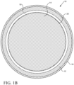
- the fuel rod 10 utilizes zirconium alloy cladding 12 with a coating 18, but more preferably a coating 18 with an interlayer 20.
- the interlayer may have a thickness of 1 to 20 microns.
- the coating may be selected from the group consisting of Cr and Cr alloys.
- the Cr alloy may, for example, be FeCrAl or FeCrAlY.
- the interlayer may be selected from the group consisting of a Mo, Ta, W, and Nb.
- Nb When the interlayer is Nb, for example, it provides very low leakage failures and resistance to very high temperatures ( ⁇ 1700 °C) during beyond design basis accidents.
- the hard Cr or Cr alloy outer layer 18 provides a very low leakage failure rate which allows the use of the water sensitive U 3 Si 2 and UB 2 or ZrB 2 .
- U 3 Si 2 provides the high density for excellent economics of operation and the high thermal conductivity and reasonable melting temperature required for good reactor operability.
- the pellet 14 with or without coating 22 may be combined with the cladding 12 having both interlayer 20 and outer layer 18. In various aspects, the pellet 14 with or without coating 22 may be combined with the cladding 12 having the coating layer 18, without interlayer 20.
- the coated zirconium alloy cladded U 3 Si 2 fuel having a boron-containing integral fuel burnable absorber described herein takes advantage of the strong points of each of the components.
- the U 3 Si 2 fuel has a low operating temperature, high thermal conductivity, and high density.
- the Zr coated cladding 12 has a high decomposition temperature, which protects the U 3 Si 2 fuel.
- the melting point and boron content of the UB 2 or ZrB 2 boron-containing integral burnable absorber produces a fuel which optimizes performance during normal operation as well as providing a high level of accident tolerance compared to the current UO 2 fueled/Zr clad nuclear fuel component combination.
- Fig. 4 illustrates the phase diagram showing the eutectic for the Nb, Cr combination.
- the phase diagram plots relative concentrations of Nb and Cr along the horizontal axis, and temperature along the vertical axis.
- the eutectic point is the point at which the liquid phase (L) borders directly on the solid phase (composed of both Nb and Cr), representing the minimum melting temperature of any possible alloy of Nb and Cr.
- a boron-containing integral fuel burnable absorber such as UB 2 or ZrB 2
- UB 2 or ZrB 2 provides a means of controlling the high initial nuclear reactivity of the U 3 Si 2 due to its high density by providing an economical means of adding boron to U 3 Si 2 , and in various aspects, adding enough boron to the U 3 Si 2 powder before pelleting. Further, the U 3 Si 2 does not react with UB 2 or ZrB 2 , thus, in various alternative aspects, allowing particles of boron-containing integral fuel burnable absorber to be added to the U 3 Si 2 powder before sintering.
- the tubes, rods, slugs and pellets described herein may be machined or formed by any method known to those skilled in the art. Because of the close tolerances for size, configuration, and other properties identified herein and those known to be relevant in the nuclear industry, precision manufacturing methods should be used.
- the fuel pellets 14 may be formed by known methods of manufacturing pellets in other commercial contexts.
- the U 3 Si 2 fuel in powder or particulate form may be formed into a pellet by first homogenizing the particles to ensure relative uniformity in terms of particle size distribution and surface area.
- the integral fuel burnable absorber, UB 2 or ZrB 2 for example, also in powder or particulate form, and in certain aspects, other additives, such as lubricants and pore-forming agents, would be added.
- the integral fuel burnable absorber content in the U 3 Si 2 pellet may be between 100 ppm and 10000 ppm, and in various aspects, may be about 1000 ppm.
- the U 3 Si 2 and boron-containing integral fuel burnable absorber particles may be formed into pellets by compressing the mixture of particles in suitable commercially available mechanical or hydraulic presses to achieve the desired "green" density and strength.
- a basic press may incorporate a die platen with single action capability while the most complex styles have multiple moving platens to form "multi-level" parts. Presses are available in a wide range of tonnage capability. The tonnage required to press powder into the desired compact pellet shape is determined by multiplying the projected surface area of the part by a load factor determined by the compressibility characteristics of the powder.
- the mixture of particles is filled into a die.
- the rate of die filling is based largely on the flowability of the particles.
- the particles may be fed into a die and pressed biaxially into cylindrical pellets using a load of several hundred MPa.
- the pellets 14 are sintered by heating in a furnace at temperatures varying with the material being sintered under a controlled atmosphere, usually comprised of argon. Sintering is a thermal process that consolidates the green pellets by converting the mechanical bonds of the particles formed during compression into stronger bonds and greatly strengthened pellets.
- the compressed and sintered pellets are then cooled and machined to the desired dimensions. Exemplary pellets may be about one centimeter, or slightly less, in diameter, and one centimeter, or slightly more, in length.
- the integral fuel burnable absorber is not intermixed with the fissile material in the pellet 14, but applied as a coating 22 to the outer surface of the pellet 14.
- the application of the UB 2 or ZrB 2 to the surface of the pellet 14 may be by any known method, such as a spray method or another method of coating.
- the fuel pellets 14, either coated with or intermixed with, the integral fuel burnable absorber are stacked in a Zr or Zr alloy cladding 12.
- the cladding 12 will have been coated with a Cr coating 18, which may be applied using a thermal deposition process, such as a cold spray process.
- the intermediate Nb interlayer 20 will be deposited on the Zr cladding 12 first and may be ground and polished before deposition of the outer Cr layer 18, which can be ground and polished thereafter.
- the interlayer 20 may be deposited by using a physical vapor deposition method, such as cathodic arc physical vapor deposition, or a hot spray process, such as a plasma arc spray method.
- Cathodic arc vapor deposition involves a source material and a substrate to be coated placed in an evacuated deposition chamber.
- the chamber contains only a relatively small amount of gas.
- the negative lead of a direct current (DC) power supply is attached to the source material (the "cathode") and the positive lead is attached to an anode.
- the positive lead is attached to the deposition chamber, thereby making the chamber the anode.
- the electric arc is used to vaporize material from the cathode target. The vaporized material then condenses on the substrate, forming the desired layer.
- the temperature will depend on the Joule -Thomson cooling coefficient of the particular gas used as the carrier. Whether or not a gas cools upon expansion or compression when subjected to pressure changes depends on the value of its Joule-Thomson coefficient. For positive Joule-Thomson coefficients, the carrier gas cools and must be preheated to prevent excessive cooling which can affect the performance of the cold spray process. Those skilled in the art can determine the degree of heating using well known calculations to prevent excessive cooling. See, for example, for N 2 as a carrier gas, if the inlet temperature is 130 °C, the Joule-Thomson coefficient is 0.1 °C/bar.
- the gas For the gas to impact the tube at 130 °C if its initial pressure is 10 bar ( ⁇ 146.9 psia) and the final pressure is 1 bar ( ⁇ 14.69 psia), then the gas needs to be preheated to about 9 bar * 0.1 °C/bar or about 0.9 C to about 130.9 °C.
- the temperature for helium gas as the carrier is preferably 450 °C at a pressure of 3.0 to 4.0 MPa
- the temperature for nitrogen as the carrier may be 1100 °C at a pressure of 5.0 MPa, but may also be 600 °C - 800 °C at a pressure of 3.0 to 4.0 MPa.
- the temperature and pressure variables may change depending on the type of the equipment used and that equipment can be modified to adjust the temperature, pressure and volume parameters.
- Suitable carrier gases are those that are inert or are not reactive, and those that particularly will not react with the Cr particles or the Nb interlayer or Zr substrate to be coated.
- Exemplary carrier gases include nitrogen (N 2 ), hydrogen (H 2 ), argon (Ar), carbon dioxide (CO 2 ), and helium (He).
- a high pressure gas enters through a conduit to a heater, where heating occurs quickly; substantially instantaneously.
- the gas is directed to a gun-like instrument.
- Particles of the desired coating material, in this case, Cr are held in a hopper, and are released and directed to the gun where they are forced through a nozzle towards the rod or tube substrate by a pressurized gas jet.
- the sprayed Cr particles are deposited onto rod or tube surface to form a coating comprised of the particles
- the method may further include annealing the coating.
- Annealing modifies mechanical properties and microstructure of the coated tube. Annealing involves heating the coating in the temperature range of 200 °C to 800 °C but preferably between 350 °C to 650 °C.
- the coated substrate may also be ground, buffed, polished, or otherwise further processed following the coating or annealing steps by any of a variety of known means to achieve a smoother surface finish.
Landscapes
- Engineering & Computer Science (AREA)
- Physics & Mathematics (AREA)
- Plasma & Fusion (AREA)
- General Engineering & Computer Science (AREA)
- High Energy & Nuclear Physics (AREA)
- Chemical & Material Sciences (AREA)
- Chemical Kinetics & Catalysis (AREA)
- Metallurgy (AREA)
- Manufacturing & Machinery (AREA)
- Dispersion Chemistry (AREA)
- Ceramic Engineering (AREA)
- Monitoring And Testing Of Nuclear Reactors (AREA)
- Other Surface Treatments For Metallic Materials (AREA)
- Coating By Spraying Or Casting (AREA)
Claims (16)
- Störfalltoleranter Brennstoffstab (10) für Leicht- und Schwerwasserreaktoren, umfassend:einen Nuklearbrennstoff, ausgewählt aus der Gruppe, die U3Si2 und UN umfasst, in Form eines Pellets (14); einen borhaltigen Brennstoff mit integriertem abbrennbaren Absorber, vermischt mit dem Nuklearbrennstoff im Pellet (14); undein zirkonhaltiges Umhüllungsmaterial (12) zum Umhüllen des Brennstoffs mit integriertem abbrennbaren Absorber, vermischt mit dem Nuklearbrennstoff in dem Pellet (14), wobei das Umhüllungsmaterial (12) eine darauf aufgebrachte Beschichtung (18) aufweist.
- Brennstab (10) nach Anspruch 1, ferner umfassend eine Zwischenschicht (20), angeordnet zwischen dem Umhüllungsmaterial (12) und der Beschichtung (18).
- Brennstab (10) nach Anspruch 2, wobei die Zwischenschicht (20) eine Dicke von 1 bis 20 Mikrometern aufweist.
- Brennstab (10) nach Anspruch 2, wobei die Zwischenschicht (20) aus Molybdän, Tantal, Wolfram und Niob hergestellt ist.
- Brennstab (10) nach Anspruch 2, wobei die Zwischenschicht (20) durch einen Heißspritzprozess auf das Umhüllungsmaterial (12) aufgebracht ist.
- Brennstab (10) nach Anspruch 5, wobei der Heißspritzprozess ein Plasmalichtbogenprozess ist.
- Brennstab nach Anspruch 1, wobei die Beschichtung aus der Gruppe ausgewählt ist, die aus Chrom und einer Chromlegierung besteht.
- Brennstab nach Anspruch 7, wobei die Chromlegierung aus der Gruppe ausgewählt ist, die aus FeCrAl und FeCrAlY besteht.
- Brennstab (10) nach Anspruch 1, wobei die Beschichtung (18) eine Dicke von 5 bis 50 Mikrometern aufweist.
- Brennstab (10) nach Anspruch 1, wobei die Beschichtung (18) durch einen Kaltspritzprozess auf das Umhüllungsmaterial (12) aufgebracht ist.
- Brennstab (10) nach Anspruch 1, wobei der Brennstoff mit integriertem abbrennbaren Absorber aus der Gruppe ausgewählt ist, die aus UB2 und ZrB2 besteht.
- Brennstab (10) nach Anspruch 1, wobei der Gehalt des Brennstoffs mit integriertem abbrennbaren Absorber im Pellet (14) zwischen 100 ppm und 10000 ppm liegt.
- Brennstab (10) nach Anspruch 1, wobei der Gehalt an dem Isotop B10 des integrierten abbrennbaren Absorbers zwischen 1 % und 90 % liegt.
- Brennstab (10) nach Anspruch 1, wobei der Nuklearbrennstoff U3Si2 mit einer Dichte zwischen 80 % und 99 % der theoretischen Dichte umfasst.
- Brennstab (10) nach Anspruch 1, wobei der Nuklearbrennstoff UN umfasst, der Stickstoff aus natürlichem Stickstoff und in dem Isotop von 15N angereichertem Stickstoff ausgewählt ist und der UN eine Dichte zwischen 80 % und 99 % der theoretischen Dichte aufweist.
- Brennstab (10) nach Anspruch 1, wobei der Brennstoff mit integriertem abbrennbaren Absorber UB2 ist.
Applications Claiming Priority (2)
| Application Number | Priority Date | Filing Date | Title |
|---|---|---|---|
| US201762579340P | 2017-10-31 | 2017-10-31 | |
| PCT/US2018/058158 WO2019125604A2 (en) | 2017-10-31 | 2018-10-30 | High temperature nuclear fuel system for thermal neutron reactors |
Publications (3)
| Publication Number | Publication Date |
|---|---|
| EP3704714A2 EP3704714A2 (de) | 2020-09-09 |
| EP3704714A4 EP3704714A4 (de) | 2021-08-25 |
| EP3704714B1 true EP3704714B1 (de) | 2024-12-04 |
Family
ID=66327514
Family Applications (1)
| Application Number | Title | Priority Date | Filing Date |
|---|---|---|---|
| EP18892438.5A Active EP3704714B1 (de) | 2017-10-31 | 2018-10-30 | Hochtemperatur-kernbrennstoffsystem für thermische neutronenreaktoren |
Country Status (6)
| Country | Link |
|---|---|
| US (1) | US20190139654A1 (de) |
| EP (1) | EP3704714B1 (de) |
| JP (1) | JP2021501335A (de) |
| KR (1) | KR20200089680A (de) |
| ES (1) | ES3018270T3 (de) |
| WO (1) | WO2019125604A2 (de) |
Families Citing this family (10)
| Publication number | Priority date | Publication date | Assignee | Title |
|---|---|---|---|---|
| US11488730B2 (en) | 2017-03-17 | 2022-11-01 | Westinghouse Electric Company Llc | Coated fuel pellets with enhanced water and steam oxidation resistance |
| CN110277177B (zh) * | 2019-06-06 | 2020-11-24 | 中国原子能科学研究院 | 一种靶件内燃料芯块与包壳间隙闭合方法 |
| CN110415845B (zh) * | 2019-08-06 | 2021-06-11 | 中国核动力研究设计院 | 一种高铀密度复合燃料芯块及其制备方法 |
| KR20220116338A (ko) | 2020-01-09 | 2022-08-22 | 웨스팅하우스 일렉트릭 컴퍼니 엘엘씨 | 핵연료 집합체 및 그 제조 방법 |
| JP2023545059A (ja) * | 2020-10-07 | 2023-10-26 | ウエスチングハウス・エレクトリック・カンパニー・エルエルシー | コーティングが施され、耐水性及び蒸気による酸化に対する耐性が高められた燃料ペレット |
| FR3115154B1 (fr) * | 2020-10-13 | 2023-05-12 | Framatome Sa | Crayon de combustible nucléaire et procédé de fabrication |
| CN113035385B (zh) * | 2021-03-04 | 2024-04-09 | 上海核工程研究设计院股份有限公司 | 一种含硼硅化铀整体型可燃毒物芯块 |
| US12437884B2 (en) * | 2021-05-19 | 2025-10-07 | Westinghouse Electric Company Llc | Nuclear fuel rod having cladding with varying diameter |
| US20220384062A1 (en) * | 2021-05-27 | 2022-12-01 | Westinghouse Electric Company Llc | Cathodic arc applied randomized grain structured coatings on zirconium alloy nuclear fuel cladding |
| CN114657525B (zh) * | 2022-03-30 | 2023-05-02 | 西安交通大学 | 一种FeCrAl/Ta合金涂层及其制备方法 |
Family Cites Families (10)
| Publication number | Priority date | Publication date | Assignee | Title |
|---|---|---|---|---|
| US4649023A (en) | 1985-01-22 | 1987-03-10 | Westinghouse Electric Corp. | Process for fabricating a zirconium-niobium alloy and articles resulting therefrom |
| US4717534A (en) * | 1985-02-19 | 1988-01-05 | Westinghouse Electric Corp. | Nuclear fuel cladding containing a burnable absorber |
| US5319690A (en) * | 1992-06-30 | 1994-06-07 | Combustion Engineering Inc. | Internal fuel rod coating comprising metal silicates |
| US9284629B2 (en) | 2004-03-23 | 2016-03-15 | Westinghouse Electric Company Llc | Zirconium alloys with improved corrosion/creep resistance due to final heat treatments |
| US7139360B2 (en) * | 2004-10-14 | 2006-11-21 | Westinghouse Electric Co. Llc | Use of boron or enriched boron 10 in UO2 |
| JP2009092619A (ja) * | 2007-10-12 | 2009-04-30 | Global Nuclear Fuel-Japan Co Ltd | 燃料集合体、その部品、それらの製造方法、および、チャンネルボックス |
| US20110206174A1 (en) * | 2010-02-22 | 2011-08-25 | Westinghouse Electric Sweden Ab | Nuclear fuel, a fuel element, a fuel assembly and a method of manufacturing a nuclear fuel |
| US9911511B2 (en) * | 2012-12-28 | 2018-03-06 | Global Nuclear Fuel—Americas, LLC | Fuel rods with wear-inhibiting coatings and methods of making the same |
| US9721676B2 (en) * | 2014-05-27 | 2017-08-01 | Westinghouse Electric Company, Llc | Deposition of a protective coating including metal-containing and chromium-containing layers on zirconium alloy for nuclear power applications |
| FR3025929B1 (fr) * | 2014-09-17 | 2016-10-21 | Commissariat Energie Atomique | Gaines de combustible nucleaire, procedes de fabrication et utilisation contre l'oxydation. |
-
2018
- 2018-10-30 WO PCT/US2018/058158 patent/WO2019125604A2/en not_active Ceased
- 2018-10-30 US US16/174,767 patent/US20190139654A1/en not_active Abandoned
- 2018-10-30 ES ES18892438T patent/ES3018270T3/es active Active
- 2018-10-30 KR KR1020207015151A patent/KR20200089680A/ko not_active Ceased
- 2018-10-30 JP JP2020543267A patent/JP2021501335A/ja active Pending
- 2018-10-30 EP EP18892438.5A patent/EP3704714B1/de active Active
Also Published As
| Publication number | Publication date |
|---|---|
| JP2021501335A (ja) | 2021-01-14 |
| EP3704714A4 (de) | 2021-08-25 |
| ES3018270T3 (en) | 2025-05-14 |
| US20190139654A1 (en) | 2019-05-09 |
| KR20200089680A (ko) | 2020-07-27 |
| WO2019125604A3 (en) | 2019-09-26 |
| EP3704714A2 (de) | 2020-09-09 |
| WO2019125604A2 (en) | 2019-06-27 |
Similar Documents
| Publication | Publication Date | Title |
|---|---|---|
| EP3704714B1 (de) | Hochtemperatur-kernbrennstoffsystem für thermische neutronenreaktoren | |
| US4894203A (en) | Nuclear fuel element having oxidation resistant cladding | |
| EP3335220B1 (de) | Korrosions- und verschleissfeste beschichtung auf einer zirkoniumlegierungsverkleidung und zugehöriges verfahren | |
| EP3685407B1 (de) | Keramisches hochtemperatur-kernbrennstoffsystem für leichtwasserreaktoren und bleigekühlte schnelle reaktoren | |
| US12183474B2 (en) | Control rods for light water reactors | |
| US4818477A (en) | PCI resistant fuel and method and apparatus for controlling reactivity in a reactor core | |
| EP0287875B1 (de) | Kern-Brennelementzirkoniumhüllrohr für einen Druckwasserreaktor | |
| KR20240014490A (ko) | 지르코늄 합금 핵연료 클래딩 상에 캐소드 아크 적용된 무작위 그레인 구조 코팅 | |
| Sundaram et al. | Nuclear fuels and development of nuclear fuel elements | |
| KR20250107854A (ko) | 박벽 클래딩 인장 강도를 증가시켜 우라늄 로딩을 증가시키기 위한 산화 내성 코팅의 용도 | |
| CA1209727A (en) | Buried zirconium layer | |
| Ransohoff | Engineering Aspects of Fuel Elements | |
| Cheng | Fuel behaviour in the case of severe accidents and potential ATF designs. Fuel Behavior in Severe Accidents and Potential Accident Tolerance Fuel Designs | |
| Rao et al. | Materials for reactor technology | |
| Bush | MATERIALS FOR NUCLEAR REACTORS. |
Legal Events
| Date | Code | Title | Description |
|---|---|---|---|
| STAA | Information on the status of an ep patent application or granted ep patent |
Free format text: STATUS: THE INTERNATIONAL PUBLICATION HAS BEEN MADE |
|
| PUAI | Public reference made under article 153(3) epc to a published international application that has entered the european phase |
Free format text: ORIGINAL CODE: 0009012 |
|
| STAA | Information on the status of an ep patent application or granted ep patent |
Free format text: STATUS: REQUEST FOR EXAMINATION WAS MADE |
|
| 17P | Request for examination filed |
Effective date: 20200515 |
|
| AK | Designated contracting states |
Kind code of ref document: A2 Designated state(s): AL AT BE BG CH CY CZ DE DK EE ES FI FR GB GR HR HU IE IS IT LI LT LU LV MC MK MT NL NO PL PT RO RS SE SI SK SM TR |
|
| AX | Request for extension of the european patent |
Extension state: BA ME |
|
| RIN1 | Information on inventor provided before grant (corrected) |
Inventor name: LAHODA, EDWARD J. Inventor name: FRANCESCHINI, FAUSTO Inventor name: XU, PENG Inventor name: SHAH, HEMANT Inventor name: OELRICH, ROBERT L., JR. Inventor name: WRIGHT, JONATHAN Inventor name: ROMERO, JAVIER Inventor name: BOYLAN, FRANK A. Inventor name: RAY, SUMIT |
|
| RIN1 | Information on inventor provided before grant (corrected) |
Inventor name: WRIGHT, JONATHAN Inventor name: LAHODA, EDWARD J. Inventor name: BOYLAN, FRANK A. Inventor name: RAY, SUMIT Inventor name: SHAH, HEMANT Inventor name: OELRICH, ROBERT L., JR. Inventor name: XU, PENG Inventor name: ROMERO, JAVIER Inventor name: FRANCESCHINI, FAUSTO |
|
| DAV | Request for validation of the european patent (deleted) | ||
| DAX | Request for extension of the european patent (deleted) | ||
| A4 | Supplementary search report drawn up and despatched |
Effective date: 20210726 |
|
| RIC1 | Information provided on ipc code assigned before grant |
Ipc: G21C 3/60 20060101AFI20210720BHEP Ipc: G21C 3/04 20060101ALI20210720BHEP Ipc: G21C 9/033 20060101ALI20210720BHEP Ipc: G21C 3/07 20060101ALI20210720BHEP Ipc: G21C 3/20 20060101ALI20210720BHEP Ipc: G21C 7/04 20060101ALI20210720BHEP Ipc: G21C 21/02 20060101ALI20210720BHEP |
|
| GRAP | Despatch of communication of intention to grant a patent |
Free format text: ORIGINAL CODE: EPIDOSNIGR1 |
|
| STAA | Information on the status of an ep patent application or granted ep patent |
Free format text: STATUS: GRANT OF PATENT IS INTENDED |
|
| RIC1 | Information provided on ipc code assigned before grant |
Ipc: G21C 21/02 20060101ALI20240510BHEP Ipc: G21C 7/04 20060101ALI20240510BHEP Ipc: G21C 3/20 20060101ALI20240510BHEP Ipc: G21C 3/07 20060101ALI20240510BHEP Ipc: G21C 9/033 20060101ALI20240510BHEP Ipc: G21C 3/04 20060101ALI20240510BHEP Ipc: G21C 3/60 20060101AFI20240510BHEP |
|
| INTG | Intention to grant announced |
Effective date: 20240529 |
|
| GRAS | Grant fee paid |
Free format text: ORIGINAL CODE: EPIDOSNIGR3 |
|
| GRAA | (expected) grant |
Free format text: ORIGINAL CODE: 0009210 |
|
| STAA | Information on the status of an ep patent application or granted ep patent |
Free format text: STATUS: THE PATENT HAS BEEN GRANTED |
|
| AK | Designated contracting states |
Kind code of ref document: B1 Designated state(s): AL AT BE BG CH CY CZ DE DK EE ES FI FR GB GR HR HU IE IS IT LI LT LU LV MC MK MT NL NO PL PT RO RS SE SI SK SM TR |
|
| REG | Reference to a national code |
Ref country code: GB Ref legal event code: FG4D |
|
| REG | Reference to a national code |
Ref country code: CH Ref legal event code: EP |
|
| REG | Reference to a national code |
Ref country code: DE Ref legal event code: R096 Ref document number: 602018077388 Country of ref document: DE |
|
| REG | Reference to a national code |
Ref country code: IE Ref legal event code: FG4D |
|
| REG | Reference to a national code |
Ref country code: LT Ref legal event code: MG9D Ref country code: SE Ref legal event code: TRGR |
|
| REG | Reference to a national code |
Ref country code: NL Ref legal event code: MP Effective date: 20241204 |
|
| PG25 | Lapsed in a contracting state [announced via postgrant information from national office to epo] |
Ref country code: HR Free format text: LAPSE BECAUSE OF FAILURE TO SUBMIT A TRANSLATION OF THE DESCRIPTION OR TO PAY THE FEE WITHIN THE PRESCRIBED TIME-LIMIT Effective date: 20241204 |
|
| PG25 | Lapsed in a contracting state [announced via postgrant information from national office to epo] |
Ref country code: FI Free format text: LAPSE BECAUSE OF FAILURE TO SUBMIT A TRANSLATION OF THE DESCRIPTION OR TO PAY THE FEE WITHIN THE PRESCRIBED TIME-LIMIT Effective date: 20241204 |
|
| PG25 | Lapsed in a contracting state [announced via postgrant information from national office to epo] |
Ref country code: BG Free format text: LAPSE BECAUSE OF FAILURE TO SUBMIT A TRANSLATION OF THE DESCRIPTION OR TO PAY THE FEE WITHIN THE PRESCRIBED TIME-LIMIT Effective date: 20241204 |
|
| PG25 | Lapsed in a contracting state [announced via postgrant information from national office to epo] |
Ref country code: NO Free format text: LAPSE BECAUSE OF FAILURE TO SUBMIT A TRANSLATION OF THE DESCRIPTION OR TO PAY THE FEE WITHIN THE PRESCRIBED TIME-LIMIT Effective date: 20250304 |
|
| PG25 | Lapsed in a contracting state [announced via postgrant information from national office to epo] |
Ref country code: GR Free format text: LAPSE BECAUSE OF FAILURE TO SUBMIT A TRANSLATION OF THE DESCRIPTION OR TO PAY THE FEE WITHIN THE PRESCRIBED TIME-LIMIT Effective date: 20250305 Ref country code: LV Free format text: LAPSE BECAUSE OF FAILURE TO SUBMIT A TRANSLATION OF THE DESCRIPTION OR TO PAY THE FEE WITHIN THE PRESCRIBED TIME-LIMIT Effective date: 20241204 |
|
| PG25 | Lapsed in a contracting state [announced via postgrant information from national office to epo] |
Ref country code: RS Free format text: LAPSE BECAUSE OF FAILURE TO SUBMIT A TRANSLATION OF THE DESCRIPTION OR TO PAY THE FEE WITHIN THE PRESCRIBED TIME-LIMIT Effective date: 20250304 |
|
| PG25 | Lapsed in a contracting state [announced via postgrant information from national office to epo] |
Ref country code: NL Free format text: LAPSE BECAUSE OF FAILURE TO SUBMIT A TRANSLATION OF THE DESCRIPTION OR TO PAY THE FEE WITHIN THE PRESCRIBED TIME-LIMIT Effective date: 20241204 |
|
| REG | Reference to a national code |
Ref country code: AT Ref legal event code: MK05 Ref document number: 1749072 Country of ref document: AT Kind code of ref document: T Effective date: 20241204 |
|
| PG25 | Lapsed in a contracting state [announced via postgrant information from national office to epo] |
Ref country code: SM Free format text: LAPSE BECAUSE OF FAILURE TO SUBMIT A TRANSLATION OF THE DESCRIPTION OR TO PAY THE FEE WITHIN THE PRESCRIBED TIME-LIMIT Effective date: 20241204 |
|
| PG25 | Lapsed in a contracting state [announced via postgrant information from national office to epo] |
Ref country code: PL Free format text: LAPSE BECAUSE OF FAILURE TO SUBMIT A TRANSLATION OF THE DESCRIPTION OR TO PAY THE FEE WITHIN THE PRESCRIBED TIME-LIMIT Effective date: 20241204 |
|
| PG25 | Lapsed in a contracting state [announced via postgrant information from national office to epo] |
Ref country code: IS Free format text: LAPSE BECAUSE OF FAILURE TO SUBMIT A TRANSLATION OF THE DESCRIPTION OR TO PAY THE FEE WITHIN THE PRESCRIBED TIME-LIMIT Effective date: 20250404 |
|
| PG25 | Lapsed in a contracting state [announced via postgrant information from national office to epo] |
Ref country code: PT Free format text: LAPSE BECAUSE OF FAILURE TO SUBMIT A TRANSLATION OF THE DESCRIPTION OR TO PAY THE FEE WITHIN THE PRESCRIBED TIME-LIMIT Effective date: 20250404 |
|
| PG25 | Lapsed in a contracting state [announced via postgrant information from national office to epo] |
Ref country code: EE Free format text: LAPSE BECAUSE OF FAILURE TO SUBMIT A TRANSLATION OF THE DESCRIPTION OR TO PAY THE FEE WITHIN THE PRESCRIBED TIME-LIMIT Effective date: 20241204 |
|
| PG25 | Lapsed in a contracting state [announced via postgrant information from national office to epo] |
Ref country code: AT Free format text: LAPSE BECAUSE OF FAILURE TO SUBMIT A TRANSLATION OF THE DESCRIPTION OR TO PAY THE FEE WITHIN THE PRESCRIBED TIME-LIMIT Effective date: 20241204 Ref country code: RO Free format text: LAPSE BECAUSE OF FAILURE TO SUBMIT A TRANSLATION OF THE DESCRIPTION OR TO PAY THE FEE WITHIN THE PRESCRIBED TIME-LIMIT Effective date: 20241204 |
|
| PG25 | Lapsed in a contracting state [announced via postgrant information from national office to epo] |
Ref country code: SK Free format text: LAPSE BECAUSE OF FAILURE TO SUBMIT A TRANSLATION OF THE DESCRIPTION OR TO PAY THE FEE WITHIN THE PRESCRIBED TIME-LIMIT Effective date: 20241204 |
|
| PG25 | Lapsed in a contracting state [announced via postgrant information from national office to epo] |
Ref country code: CZ Free format text: LAPSE BECAUSE OF FAILURE TO SUBMIT A TRANSLATION OF THE DESCRIPTION OR TO PAY THE FEE WITHIN THE PRESCRIBED TIME-LIMIT Effective date: 20241204 |
|
| PG25 | Lapsed in a contracting state [announced via postgrant information from national office to epo] |
Ref country code: IT Free format text: LAPSE BECAUSE OF FAILURE TO SUBMIT A TRANSLATION OF THE DESCRIPTION OR TO PAY THE FEE WITHIN THE PRESCRIBED TIME-LIMIT Effective date: 20241204 |
|
| REG | Reference to a national code |
Ref country code: DE Ref legal event code: R097 Ref document number: 602018077388 Country of ref document: DE |
|
| PG25 | Lapsed in a contracting state [announced via postgrant information from national office to epo] |
Ref country code: DK Free format text: LAPSE BECAUSE OF FAILURE TO SUBMIT A TRANSLATION OF THE DESCRIPTION OR TO PAY THE FEE WITHIN THE PRESCRIBED TIME-LIMIT Effective date: 20241204 |
|
| PLBE | No opposition filed within time limit |
Free format text: ORIGINAL CODE: 0009261 |
|
| STAA | Information on the status of an ep patent application or granted ep patent |
Free format text: STATUS: NO OPPOSITION FILED WITHIN TIME LIMIT |
|
| 26N | No opposition filed |
Effective date: 20250905 |
|
| PGFP | Annual fee paid to national office [announced via postgrant information from national office to epo] |
Ref country code: DE Payment date: 20250919 Year of fee payment: 8 |
|
| PGFP | Annual fee paid to national office [announced via postgrant information from national office to epo] |
Ref country code: GB Payment date: 20251024 Year of fee payment: 8 |
|
| PGFP | Annual fee paid to national office [announced via postgrant information from national office to epo] |
Ref country code: FR Payment date: 20251017 Year of fee payment: 8 |
|
| PGFP | Annual fee paid to national office [announced via postgrant information from national office to epo] |
Ref country code: SE Payment date: 20251017 Year of fee payment: 8 |
|
| PGFP | Annual fee paid to national office [announced via postgrant information from national office to epo] |
Ref country code: ES Payment date: 20251113 Year of fee payment: 8 |