EP3592610B1 - Aufnahmeeinrichtung für leitungselemente in einer durchführung eines fahrzeugs - Google Patents
Aufnahmeeinrichtung für leitungselemente in einer durchführung eines fahrzeugs Download PDFInfo
- Publication number
- EP3592610B1 EP3592610B1 EP18723417.4A EP18723417A EP3592610B1 EP 3592610 B1 EP3592610 B1 EP 3592610B1 EP 18723417 A EP18723417 A EP 18723417A EP 3592610 B1 EP3592610 B1 EP 3592610B1
- Authority
- EP
- European Patent Office
- Prior art keywords
- rail vehicle
- facility
- feed
- section
- heat
- Prior art date
- Legal status (The legal status is an assumption and is not a legal conclusion. Google has not performed a legal analysis and makes no representation as to the accuracy of the status listed.)
- Active
Links
Images



Classifications
-
- B—PERFORMING OPERATIONS; TRANSPORTING
- B60—VEHICLES IN GENERAL
- B60R—VEHICLES, VEHICLE FITTINGS, OR VEHICLE PARTS, NOT OTHERWISE PROVIDED FOR
- B60R16/00—Electric or fluid circuits specially adapted for vehicles and not otherwise provided for; Arrangement of elements of electric or fluid circuits specially adapted for vehicles and not otherwise provided for
- B60R16/02—Electric or fluid circuits specially adapted for vehicles and not otherwise provided for; Arrangement of elements of electric or fluid circuits specially adapted for vehicles and not otherwise provided for electric constitutive elements
- B60R16/0207—Wire harnesses
- B60R16/0215—Protecting, fastening and routing means therefor
-
- B—PERFORMING OPERATIONS; TRANSPORTING
- B61—RAILWAYS
- B61F—RAIL VEHICLE SUSPENSIONS, e.g. UNDERFRAMES, BOGIES OR ARRANGEMENTS OF WHEEL AXLES; RAIL VEHICLES FOR USE ON TRACKS OF DIFFERENT WIDTH; PREVENTING DERAILING OF RAIL VEHICLES; WHEEL GUARDS, OBSTRUCTION REMOVERS OR THE LIKE FOR RAIL VEHICLES
- B61F1/00—Underframes
-
- B—PERFORMING OPERATIONS; TRANSPORTING
- B62—LAND VEHICLES FOR TRAVELLING OTHERWISE THAN ON RAILS
- B62D—MOTOR VEHICLES; TRAILERS
- B62D21/00—Understructures, i.e. chassis frame on which a vehicle body may be mounted
- B62D21/17—Understructures, i.e. chassis frame on which a vehicle body may be mounted forming fluid or electrical conduit means or having other means to accommodate the transmission of a force or signal
-
- H—ELECTRICITY
- H02—GENERATION; CONVERSION OR DISTRIBUTION OF ELECTRIC POWER
- H02G—INSTALLATION OF ELECTRIC CABLES OR LINES, OR OF COMBINED OPTICAL AND ELECTRIC CABLES OR LINES
- H02G3/00—Installations of electric cables or lines or protective tubing therefor in or on buildings, equivalent structures or vehicles
- H02G3/02—Details
- H02G3/04—Protective tubing or conduits, e.g. cable ladders or cable troughs
- H02G3/0406—Details thereof
- H02G3/0412—Heat or fire protective means
-
- H—ELECTRICITY
- H02—GENERATION; CONVERSION OR DISTRIBUTION OF ELECTRIC POWER
- H02G—INSTALLATION OF ELECTRIC CABLES OR LINES, OR OF COMBINED OPTICAL AND ELECTRIC CABLES OR LINES
- H02G3/00—Installations of electric cables or lines or protective tubing therefor in or on buildings, equivalent structures or vehicles
- H02G3/22—Installations of cables or lines through walls, floors or ceilings, e.g. into buildings
-
- F—MECHANICAL ENGINEERING; LIGHTING; HEATING; WEAPONS; BLASTING
- F16—ENGINEERING ELEMENTS AND UNITS; GENERAL MEASURES FOR PRODUCING AND MAINTAINING EFFECTIVE FUNCTIONING OF MACHINES OR INSTALLATIONS; THERMAL INSULATION IN GENERAL
- F16L—PIPES; JOINTS OR FITTINGS FOR PIPES; SUPPORTS FOR PIPES, CABLES OR PROTECTIVE TUBING; MEANS FOR THERMAL INSULATION IN GENERAL
- F16L3/00—Supports for pipes, cables or protective tubing, e.g. hangers, holders, clamps, cleats, clips, brackets
- F16L3/22—Supports for pipes, cables or protective tubing, e.g. hangers, holders, clamps, cleats, clips, brackets specially adapted for supporting a number of parallel pipes at intervals
- F16L3/223—Supports for pipes, cables or protective tubing, e.g. hangers, holders, clamps, cleats, clips, brackets specially adapted for supporting a number of parallel pipes at intervals each support having one transverse base for supporting the pipes
Definitions
- the invention relates to a rail vehicle with at least one component which is designed as a cross member which is supported on a bogie of the rail vehicle and has at least one bushing, with a device for receiving at least two line elements being arranged in the at least one bushing.
- thermal problems can occur when routing line elements through bushings of components. If the line elements are, for example, electrical conductors of a cable through which high currents flow, power losses occur that can lead to an increase in cable temperatures.
- the insulating material encasing a conductor usually only has a low coefficient of thermal conductivity, which makes it difficult for the heat generated in the cable to be released to the environment.
- the temperature rise can be particularly high in cable bundles because adjacent cables or cable insulation represent additional thermal insulation. This problem can also be exacerbated in narrow feedthroughs through components.
- bushings are generally selected to be as small as possible in terms of their cross section so as not to impair the mechanical stability of the component.
- the object of the invention is to achieve better heat dissipation of heat given off by the line elements in the area of a bushing. This object is achieved by a device with the features solved according to the independent patent claim. Furthermore, the
- a device for accommodating at least two line elements in a bushing of a vehicle has at least one separating element made of a heat-conducting material, by which the at least two line elements are separated from one another.
- thermoly conductive separating element or elements achieve additional heat dissipation in the longitudinal direction of the line and thus out of the bushing.
- a thermal decoupling between the line elements is advantageously achieved, wherein the thermal decoupling can in particular prevent a particularly strongly heated or hot line element from heating up an adjacent other line element, as a result of which its insulation is possibly damaged.
- the line elements are electrical cables, each with at least one electrical conductor.
- the line elements can also be fluid lines or a combination of electrical cables and lines for fluid transport.
- the leadthrough is a leadthrough of a component of the rail vehicle.
- the component fulfills an additional function as a cross member of the vehicle.
- the component consists of a thermally conductive material.
- a line bundle consisting of a plurality of line elements is routed through the bushing, each of the line elements of the line bundle being separated from every other line element by at least one separating element.
- the device has at least one spacer element made of a heat-conducting material for transporting heat from the device into the component, with the at least one spacer element being arranged between the device and an inner wall of the bushing.
- At least one heat-conducting spacer element is positioned between the device and the inner wall of the bushing, in particular clamped in, which has a radial heat flow of allows the device via the inner wall of the bushing in the component.
- each separating element is thermally conductively coupled to the at least one spacer element.
- the coupling can take place directly, indirectly via at least one other separating element, indirectly via an outer wall of the device, or indirectly via an outer wall of the device and at least one other separating element (32).
- the device has a plurality of receiving sections for a respective recording of a line element, for example a line bundle, with a receiving section of is separated from each other receiving section by at least one separating element.
- a line element for example a line bundle
- the device is an extruded profile element whose extrusion direction is aligned parallel to a longitudinal direction of the bushing.
- the extruded profile element preferably consists of a metal, a metal alloy or a metal-containing material.
- the extruded profile element is pushed into the passage.
- One advantage of the component according to the invention is that if the component is used as a load-bearing component in a rail vehicle, the cross-section of the bushing can be made particularly small because any thermal problems caused by heating within the bushing can be avoided by the device according to the invention with the thermally conductive separating elements can at least be reduced.
- the cross member is supported on a bogie of the rail vehicle.
- the second training third training extends Carrying out in a longitudinal direction of the vehicle, with itself the line elements routed through the passage from a section of the vehicle located in front of the chassis, in particular from a section of an underside of a car body of the vehicle located in front of the chassis, through the passage into a section of the vehicle located behind the chassis, in particular into a section behind the chassis located section of the underside of the car body, extend.
- FIG 1 shows a section of a rail vehicle 10 in a cut-open representation obliquely from the side FIG 1 not shown bogie of the rail vehicle 10 is used.
- component 11 is provided with a passage 20 that extends along longitudinal direction X of the vehicle.
- FIG 2 shows the passage 20 of the cross member 11 according to FIG FIG 1 closer in detail.
- a device 30 is used, which is preferably directly or indirectly connected to the inner wall 21 of the implementation or at least indirectly or directly thermally coupled with this.
- the device 30 is referred to below as the receiving device 30 .
- the receiving device 30 is used for inserting the line elements 15 and preferably comprises one or more heat-conducting separating elements, each of which separates at least one of the line elements 15 from at least one other of the line elements 15 .
- Embodiments of preferred recording devices 30 are described below in connection with the Figures 4 to 11 explained.
- the 3 shows the rail vehicle 10 according to FIGS Figures 1 and 2 viewed from the side in a cross section.
- the crossbeam 11 can be seen, which is supported vertically in the Z-direction on the bogie 13 and has the bushing 20 for the passage of the line elements 15 .
- the 3 shows that the bushing 20 extends in the vehicle longitudinal direction X, so that line elements 15 passed through the bushing 20 in the vehicle longitudinal direction X seen from a section 16 of the rail vehicle 10 located in front of the bogie 13 through the bushing 20 into a section located behind the bogie 13 17 of the rail vehicle 10 can reach.
- FIG 4 shows an exemplary embodiment of a receiving device 30 which is suitable for receiving the line elements 15 .
- the receiving device 30 is formed by two heat-conducting bodies 301 and 302 which are stacked one on top of the other.
- the Indian FIG 4 The lower heat-conducting body 301 rests on the inner wall 21 of the bushing 20 and is therefore coupled over a large area with the cross member 11 in terms of heat flow in the Z direction.
- the receiving device 30 is in accordance with the invention FIG 4 side by means thermally conductive spacers 50, 51 and 52 clamped in the bushing 20.
- the heat-conducting spacer elements 50, 51 and 52 thus support the radial flow of heat into the cross member 11.
- the receiving device 30 or the heat-conducting bodies 301 and 302 form receiving sections 31 for individually inserting the line elements 15.
- the receiving device 30 is equipped with separating elements 32 which separate the receiving sections 31 and thus the line elements 15 inserted therein from one another.
- the separating elements 32 are preferably good thermal conductors. It is advantageous if the separating elements 32 consist of metal, an alloy or a metal-containing material.
- the receiving device 30 rests on the lower inner wall 21, due to the radial lateral heat dissipation through the spacer elements 50, 51 and 52 and due to the separating elements 32, which allow individual heat dissipation of the heat of each individual line element 15 via the inner wall 21 into the cross member 11 allow an optimal heat dissipation of the line elements 15 within the implementation 20 is achieved.
- the separation of the line elements 15 from one another also prevents particularly hot line elements from being able to significantly heat up adjacent line elements because the separating elements 32 dissipate the heat.
- the line elements 15 can be electrical cables or else fluid lines or the like.
- the line elements 15 can be electrical cables or else fluid lines or the like.
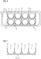
- the 5 shows the heat conducting body 301 and 302, which the receiving device 30 in the embodiment according to FIG 4 form, more in detail.
- the separating elements 32, through which the receiving sections 31 are formed in the receiving device 30, can be seen.
- the 6 shows another embodiment of a receiving device 30, which is in the implementation 20 according to Figures 1 to 3 can be used.
- the recording device 30 according to 6 is formed by two thermal conductors 310 and 311 stacked one on top of the other.
- the Indian 6 The lower heat-conducting body 310 rests over a large area on the lower inner wall 21 of the bushing 20, so that heat can be dissipated in a vertical downward direction.
- thermally conductive spacer elements 50, 51 and 52 are used, as in connection with the FIG 4 have already been addressed and explained above.
- the receiving device 30 according to 6 is equipped with separating elements 32, through which receiving sections 31 for individually receiving the line elements 15 are formed. It is advantageous if each line element 15 is separated from each of the other line elements 15 by at least one separating element 32 .
- the FIG 7 shows the thermal conductors 310 and 311 again individually in more detail. The separating elements 32 for forming the receiving sections 31 can be seen.
- the 8 shows another embodiment of a receiving device 30, which is in the passage 20 of the cross member 11 according to Figures 1 to 3 can be used.
- the receiving device 30 has individual receiving sections 31 for line elements, which are separated from one another by separating elements 32 .
- the thermally conductive separators 32 allow a radial Heat dissipation to the outside, as already mentioned above in connection with the Figures 1 to 7 has been explained.
- receiving devices 30 which have corrugated plate-like heat-conducting bodies with trough-like receiving sections.
- the receiving device 30 is formed by two heat-conducting bodies 320 and 321, which are formed by corrugated metal sheets or corrugated sheets.
- the Indian 9 The lower heat-conducting body 320 rests on the inner wall 21 of the bushing 20 and thus enables radial heat dissipation.
- the receiving device 30 is formed by three heat-conducting bodies 320, 321 and 322 in the form of corrugated sheets of metal or corrugated sheets.
- Each line element 15 or each receiving section 31 of the receiving device 30 is separated from another receiving section or another line element by at least one separating element 32 .
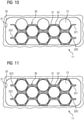
- the receiving device 30 is formed by four heat-conducting bodies 320, 321, 322 and 323 in the form of corrugated metal sheets. There is a radial heat dissipation to the outside, both vertically downwards and vertically upwards, since the receiving device 30 is thermally coupled to the inner wall 21 both at the bottom and at the top.
Landscapes
- Engineering & Computer Science (AREA)
- Architecture (AREA)
- Civil Engineering (AREA)
- Structural Engineering (AREA)
- Mechanical Engineering (AREA)
- Chemical & Material Sciences (AREA)
- Combustion & Propulsion (AREA)
- Transportation (AREA)
- Details Of Indoor Wiring (AREA)
- Cable Accessories (AREA)
- Insulators (AREA)
- Resistance Heating (AREA)
- Exhaust Gas After Treatment (AREA)
Description
- Die Erfindung bezieht sich auf ein Schienenfahrzeug mit zumindest einem Bauelement welches als Querträger ausgestaltet ist, der sich auf einem Drehgestell des Schienenfahrzeugs abstützt und zumindest eine Durchführung aufweist wobei in der zumindest eine Durchführung eine Einrichtung zur Aufnahme von zumindest zwei Leitungselementen angeordnet ist.
- Bei der Führung von Leitungselementen durch Durchführungen von Bauelementen können je nach Dimensionierung thermische Probleme auftreten. Handelt es sich bei den Leitungselementen beispielsweise um elektrische Leiter eines Kabels, durch die hohe Ströme fließen, so entstehen Verlustleistungen, die zu einem Anstieg der Kabeltemperaturen führen können. Das einen Leiter umhüllende Isoliermaterial hat in der Regel einen nur niedrigen Wärmeleitkoeffizienten, was eine Abgabe der in dem Kabel erzeugten Wärme an die Umgebung erschwert. In Kabelbündeln kann der Temperaturanstieg besonders groß ausfallen, weil benachbarte Kabel bzw. Kabelisolierungen eine zusätzliche Wärmeisolierung darstellen. In engen Durchführungen durch Bauelemente kann sich dieses Problem zudem weiter verschärfen.
- Handelt es sich bei dem Bauelement um ein tragendes Bauelement, insbesondere ein Bauelement eines Fahrzeugs, so werden Durchführungen bezüglich ihres Querschnitts in der Regel möglichst klein gewählt werden, um die mechanische Stabilität des Bauelements nicht zu beeinträchtigen.
- Der Erfindung liegt die Aufgabe zugrunde, im Bereich einer Durchführung eine bessere Wärmeabfuhr von Wärme, die von den Leitungselementen abgegeben wird, zu erzielen. Diese Aufgabe wird erfindungsgemäß durch eine Einrichtung mit den Merkmalen gemäß dem unabhängigen Patentanspruch gelöst. Ferner wird die
- Aufgabe durch die Merkmale eines Schienenfahrzeugs mit den Merkmalen der nebengeordneten Patentansprüche gelöst. Vorteilhafte Ausgestaltungen der erfindungsgemäßen Einrichtung sind in jeweiligen abhängigen Patentansprüchen angegeben.
- Gemäß einem ersten Aspekt der Erfindung weist eine Einrichtung zur Aufnahme von zumindest zwei Leitungselementen in einer Durchführung eines Fahrzeugs zumindest ein Trennelement aus einem wärmeleitenden Material auf, durch das die zumindest zwei Leitungselemente voneinander getrennt werden.
- Ein wesentlicher Vorteil der erfindungsgemäßen Einrichtung ist darin zu sehen, dass durch das oder die wärmeleitenden Trennelemente eine zusätzliche Wärmeabfuhr in Leitungslängsrichtung und damit aus der Durchführung heraus erreicht wird. Zudem wird in vorteilhafter Weise eine thermische Entkopplung zwischen den Leitungselementen erreicht, wobei die thermische Entkopplung insbesondere verhindern kann, dass ein besonders stark erwärmtes bzw. heißes Leitungselement ein benachbartes anderes Leitungselement aufheizt, wodurch dessen Isolation womöglich beschädigt wird.
- Gemäß einer ersten Weiterbildung des ersten Aspekts der Erfindung sind die Leitungselemente elektrische Kabel mit jeweils zumindest einem elektrischen Leiter. Alternativ kann es sich bei den Leitungselementen jedoch auch um Fluidleitungen bzw. um eine Kombination aus elektrischen Kabel und Leitungen für einen Fluidtransport handeln.
- Gemäß der Erfindung ist die Durchführung eine Durchführung eines Bauelements des Schienenfahrzeugs. Das Bauelement erfüllt dabei eine weitere Funktion, als ein Querträger des Fahrzeugs. Das Bauelement besteht erfindungsgemäß aus einem wärmeleitenden Material.
- Gemäß der Erfindung wird ein Leitungsbündel bestehend aus einer Mehrzahl Leitungselemente durch die Durchführung geführt, wobei jedes der Leitungselemente des Leitungsbündels von jedem anderen Leitungselement durch zumindest ein Trennelement getrennt ist.
- Gemäß einer Ausgestaltung der zweiten Weiterbildung weist die Einrichtung zumindest ein Distanzelement aus einem wärmeleitenden Material für einen Wärmetransport von der Einrichtung in das Bauelement auf, wobei das zumindest eine Distanzelement zwischen der Einrichtung und einer Innenwand der Durchführung angeordnet ist.
- Mit Blick auf eine gute Wärmeabfuhr radial nach außen, also quer oder senkrecht zur Leitungslängsrichtung bzw. quer oder senkrecht zur Längsrichtung der Durchführung, wird zwischen der Einrichtung und der Innenwand der Durchführung mindestens ein solches wärmeleitendes Distanzelement positioniert, insbesondere eingeklemmt, welches einen radialen Wärmefluss von der Einrichtung über die Innenwand der Durchführung in das Bauelement ermöglicht.
- Gemäß der Erfindung ist jedes Trennelement wärmeleitend mit dem zumindest einen Distanzelement gekoppelt. Dabei kann die Kopplung unmittelbar, mittelbar über zumindest ein anderes Trennelement, mittelbar über eine Außenwand der Einrichtung, oder mittelbar über eine Außenwand der Einrichtung und zumindest ein anderes Trennelement (32) erfolgen.
- Gemäß einer weiteren Weiterbildung der Erfindung weist die Einrichtung eine Mehrzahl Aufnahmeabschnitte für eine jeweilige Aufnahme eines Leitungselements beispielsweise eines Leitungsbündels auf, wobei ein Aufnahmeabschnitt von jedem anderen Aufnahmeabschnitt durch jeweils mindestens ein Trennelement getrennt ist.
- Gemäß einer weiteren Weiterbildung der Erfindung gemäß erstem Aspekt ist die Einrichtung ein Strangpressprofilelement, dessen Strangpressrichtung parallel zu einer Längsrichtung der Durchführung ausgerichtet ist. Dabei besteht das Strangpressprofilelement vorzugsweise aus einem Metall, einer Metalllegierung oder einem metallhaltigen Material. Beispielsweise wird das Strangpressprofilelement in die Durchführung eingeschoben.
- Ein Vorteil des erfindungsgemäßen Bauelements besteht darin, dass im Falle eines Einsatzes des Bauelements als tragendes Bauelement in einem Schienenfahrzeug, die Durchführung vom Querschnitt her besonders klein ausgeführt werden kann, weil etwaige thermische Probleme durch Erwärmung innerhalb der Durchführung durch die erfindungsgemäße Einrichtung mit den wärmeleitenden Trennelementen zumindest reduziert werden können.
- Gemäß der Erfindung stützt sich der Querträger auf einem Drehgestell des Schienenfahrzeugs ab.
- Gemäß einer wiederum auf der zweiten Weiterbildung aufbauenden dritten Weiterbildung erstreckt sich die Durchführung in einer Längsrichtung des Fahrzeugs, wobei sich die durch die Durchführung geführten Leitungselemente von einem vor dem Fahrgestell befindlichen Abschnitt des Fahrzeugs, insbesondere von einem vor dem Fahrgestell befindlichen Abschnitt einer Unterseite eines Wagenkastens des Fahrzeugs, durch die Durchführung in einen hinter dem Fahrgestell befindlichen Abschnitt des Fahrzeugs, insbesondere in einen hinter dem Fahrgestell befindlichen Abschnitt der Unterseite des Wagenkastens, erstrecken.
- Die Erfindung wird nachfolgend anhand von Ausführungsbeispielen näher erläutert. Dabei zeigen
- FIG 1
- ein erfindungsgemäßes Schienenfahrzeug mit dem Bauelement, in einer perspektivischen Ansicht einer Querschnittdarstellung,
- FIG 2
- das Bauelement gemäß
FIG 1 in einer Detaildarstellung, - FIG 3
- das Schienenfahrzeug gemäß den
Figuren 1 und 2 in einer Querschnittdarstellung von der Seite, - FIG 4
- eine in einer Durchführung des Bauelements gemäß den
Figuren 1 bis 3 angeordnete Aufnahmeeinrichtung mit Trennelementen und eingelegten Leitungselementen, - FIG 5
- Wärmeleitkörper der Aufnahmeeinrichtung gemäß
FIG 4 in einer Detailansicht, - FIG 6
- eine weitere in einer Durchführung des Bauelements gemäß den
Figuren 1 bis 3 angeordnete Aufnahmeeinrichtung, - FIG 7
- Wärmeleitkörper der Aufnahmeeinrichtung gemäß
FIG 6 in einer Detailansicht, - FIG 8
- eine weitere Aufnahmeeinrichtung zur Aufnahme von Leitungselementen, und
- FIG 9-11
- weitere Aufnahmeeinrichtungen mit wellplattenartigen Elementen.
- In den Figuren werden der Übersicht halber für identische oder vergleichbare Komponenten stets dieselben Bezugszeichen verwendet.
- Die
FIG 1 zeigt in einer aufgeschnittenen Darstellung schräg von der Seite einen Abschnitt eines Schienenfahrzeugs 10. Das Schienenfahrzeug 10 weist ein Bauelement 11 in Form eines Querträgers auf, der zum Abstützen eines Wagenkastens 12 auf einem in derFIG 1 nicht gezeigten Drehgestell des Schienenfahrzeugs 10 dient. Zum Durchführen von Leitungselementen 15 durch den Querträger 11 hindurch entlang der Fahrzeuglängsrichtung X ist das Bauelement 11 mit einer Durchführung 20 versehen, die sich entlang der Fahrzeuglängsrichtung X erstreckt. - Die
FIG 2 zeigt die Durchführung 20 des Querträgers 11 gemäßFIG 1 näher im Detail. Es lässt sich erkennen, dass in die Durchführung 20 eine Einrichtung 30 eingesetzt ist, die vorzugsweise mit der Innenwand 21 der Durchführung mittelbar oder unmittelbar verbunden oder zumindest mittelbar oder unmittelbar wärmetechnisch mit dieser gekoppelt ist. Die Einrichtung 30 wird nachfolgend als Aufnahmeeinrichtung 30 bezeichnet. Die Aufnahmeeinrichtung 30 dient zum Einlegen der Leitungselemente 15 und umfasst vorzugsweise ein oder mehrere wärmeleitende Trennelemente, die jeweils zumindest eines der Leitungselemente 15 von zumindest einem anderen der Leitungselemente 15 trennen. Ausführungsbeispiele für bevorzugte Aufnahmeeinrichtungen 30 werden weiter unten im Zusammenhang mit denFiguren 4 bis 11 erläutert. - Die
FIG 3 zeigt das Schienenfahrzeug 10 gemäß denFiguren 1 und 2 in einem Querschnitt von der Seite betrachtet. Man erkennt den Querträger 11, der sich auf dem Drehgestell 13 vertikal in Z-Richtung abstützt und die Durchführung 20 zum Durchführen der Leitungselemente 15 aufweist. DieFIG 3 zeigt, dass sich die Durchführung 20 in Fahrzeuglängsrichtung X erstreckt, so dass durch die Durchführung 20 hindurchgeführte Leitungselemente 15 in Fahrzeuglängsrichtung X gesehen von einem vor dem Drehgestell 13 befindlichen Abschnitt 16 des Schienenfahrzeugs 10 durch die Durchführung 20 hindurch in einen hinter dem Drehgestell 13 befindlichen Abschnitt 17 des Schienenfahrzeugs 10 gelangen können. - Die
FIG 4 zeigt ein Ausführungsbeispiel für eine Aufnahmeeinrichtung 30, die zur Aufnahme der Leitungselemente 15 geeignet ist. Die Aufnahmeeinrichtung 30 wird durch zwei Wärmeleitkörper 301 und 302 gebildet, die übereinander gestapelt sind. Der in derFIG 4 untere Wärmeleitkörper 301 liegt auf der Innenwand 21 der Durchführung 20 auf und ist somit großflächig mit dem Querträger 11 wärmestrommäßig in Z-Richtung gekoppelt. - Um auch in Fahrzeugquerrichtung Y einen Wärmefluss radial nach außen zu ermöglichen, ist die Aufnahmeeinrichtung 30 bei der Erfindung gemäß
FIG 4 seitlich mittels wärmeleitender Distanzelemente 50, 51 und 52 in der Durchführung 20 eingeklemmt. Die wärmeleitenden Distanzelemente 50, 51 und 52 unterstützen somit den radialen Wärmefluss in den Querträger 11. - Die Aufnahmeeinrichtung 30 bzw. die Wärmeleitkörper 301 und 302 bilden Aufnahmeabschnitte 31 zum individuellen Einlegen der Leitungselemente 15. Zu diesem Zweck ist die Aufnahmeeinrichtung 30 mit Trennelementen 32 ausgestattet, die die Aufnahmeabschnitte 31 und damit die darin eingelegten Leitungselemente 15 voneinander trennen. Die Trennelemente 32 sind vorzugsweise gut wärmeleitend. Vorteilhaft ist es, wenn die Trennelemente 32 aus Metall, einer Legierung oder einem metallhaltigen Material bestehen.
- Durch das Aufliegen der Aufnahmeeinrichtung 30 auf der unteren Innenwand 21, durch die radiale seitliche Wärmeabfuhr durch die Distanzelemente 50, 51 und 52 hindurch sowie durch die Trennelemente 32, die eine individuelle Wärmeabfuhr der Wärme jedes einzelnen Leitungselements 15 über die Innenwand 21 in den Querträger 11 ermöglichen, wird eine optimale Entwärmung der Leitungselemente 15 innerhalb der Durchführung 20 erreicht. Durch die Trennung der Leitungselemente 15 untereinander wird darüber hinaus vermieden, dass besonders heiße Leitungselemente benachbarte Leitungselemente signifikant aufheizen können, weil die Trennelemente 32 die Wärme abführen.
- Bei den Leitungselementen 15 kann es sich um elektrische Kabel oder auch um Fluidleitungen oder dergleichen handeln. Insbesondere bei mit hohen Strömen durchflossenen elektrischen Leitungen besteht das Problem einer signifikanten Erwärmung im Bereich der aus Stabilitätsgründen vom Querschnitt relativ kleinen Durchführung 20; dieses Problem wird durch die Trennelemente deutlich reduziert.
- Die
FIG 5 zeigt die Wärmeleitkörper 301 und 302, die die Aufnahmeeinrichtung 30 bei der Ausführungsvariante gemäßFIG 4 bilden, näher im Detail. Man erkennt die Trennelemente 32, durch die die Aufnahmeabschnitte 31 bei der Aufnahmeeinrichtung 30 gebildet werden. - Die
FIG 6 zeigt ein weiteres Ausführungsbeispiel für eine Aufnahmeeinrichtung 30, die in der Durchführung 20 gemäß denFiguren 1 bis 3 eingesetzt werden kann. Die Aufnahmeeinrichtung 30 gemäßFIG 6 wird durch zwei Wärmeleitkörper 310 und 311 gebildet, die übereinander gestapelt sind. Der in derFIG 6 untere Wärmeleitkörper 310 liegt großflächig auf der unteren Innenwand 21 der Durchführung 20 auf, so dass eine Wärmeabfuhr in vertikaler Richtung nach unten ermöglicht wird. - Zwecks radiale Wärmeabfuhr werden weitere wärmeleitende Distanzelemente 50, 51 und 52 eingesetzt, wie sie im Zusammenhang mit der
FIG 4 oben bereits angesprochen und erläutert worden sind. - Auch die Aufnahmeeinrichtung 30 gemäß
FIG 6 ist mit Trennelementen 32 ausgestattet, durch die Aufnahmeabschnitte 31 zur individuellen Aufnahme der Leitungselemente 15 gebildet werden. Vorteilhaft ist es, wenn jedes Leitungselement 15 von jedem der anderen Leitungselemente 15 jeweils durch mindestens ein Trennelement 32 getrennt ist. DieFIG 7 zeigt die Wärmeleitkörper 310 und 311 nochmals individuell näher im Detail. Man erkennt die Trennelemente 32 zur Bildung der Aufnahmeabschnitte 31. - Die
FIG 8 zeigt ein weiteres Ausführungsbeispiel für eine Aufnahmeeinrichtung 30, die in die Durchführung 20 des Querträgers 11 gemäß denFiguren 1 bis 3 eingesetzt werden kann. Die Aufnahmeeinrichtung 30 weist für Leitungselemente jeweils individuelle Aufnahmeabschnitte 31 auf, die voneinander durch Trennelemente 32 getrennt sind. Die wärmeleitenden Trennelemente 32 ermöglichen eine radiale Wärmeabfuhr nach außen, wie dies bereits oben im Zusammenhang mit denFiguren 1 bis 7 erläutert worden ist. - In den
Figuren 9 bis 11 werden Ausführungsbeispiele für Aufnahmeeinrichtungen 30 gezeigt, die wellplattenähnliche Wärmeleitkörper mit wannenartigen Aufnahmeabschnitten aufweisen. - Bei der Ausführungsvariante gemäß
FIG 9 wird die Aufnahmeeinrichtung 30 durch zwei Wärmeleitkörper 320 und 321 gebildet, die durch Wellbleche oder aus Wellplatten aus Metall gebildet sind. Der in derFIG 9 untere Wärmeleitkörper 320 liegt auf der Innenwand 21 der Durchführung 20 auf und ermöglicht somit eine radiale Wärmeabfuhr. - Bei der Ausführungsvariante gemäß
FIG 10 wird die Aufnahmeeinrichtung 30 durch drei Wärmeleitkörper 320, 321 und 322 in Form von Wellplatten aus Metall bzw. Wellblechen gebildet. Jedes Leitungselement 15 bzw. jeder Aufnahmeabschnitt 31 der Aufnahmeeinrichtung 30 wird jeweils durch mindestens ein Trennelement 32 von einem anderen Aufnahmeabschnitt bzw. einem anderen Leitungselement getrennt. - Bei der Ausführungsvariante gemäß
FIG 11 wird die Aufnahmeeinrichtung 30 durch vier Wärmeleitkörper 320, 321, 322 und 323 in Form von Wellplatten aus Metall gebildet. Es erfolgt eine radiale Wärmeabfuhr nach außen sowohl vertikal nach unten als auch vertikal nach oben, da die Aufnahmeeinrichtung 30 mit der Innenwand 21 sowohl unten als auch oben thermisch gekoppelt ist. - Die im Zusammenhang mit den
Figuren 4 bis 11 erläuterten Ausführungsbeispiele für Aufnahmeeinrichtungen 30 weisen gemäß den Ansprüchen folgenden Merkmale oder Eigenschaften auf: - Die Breite und Anzahl der wannenartigen Aufnahmeabschnitte 31, die Ausgestaltung der seitlichen Begrenzungen und die Länge der Wärmeleitkörper lassen sich an die jeweiligen Einbauverhältnisse wie beispielsweise die Anzahl und Dicke der aufzunehmenden Leitungen bzw. Kabel und den zur Verfügung stehenden Bauraum anpassen.
- Vorgefertigte Profile, vorzugsweise Strangpressprofile, können als Aufnahmeeinrichtungen oder als Wärmeleitkörper für Aufnahmeeinrichtungen eingesetzt werden und beispielsweise durch Sägen oder Abfräsen an die jeweilige Durchführung 20, also den jeweiligen Einsatzort adaptiert werden.
- Zusätzliche Metallkörper werden als Distanzstücke zur Wärmekopplung bzw. besserer Wärmeleitung zwischen den Wärmeleitkörpern und der Durchführung eingesetzt, um die radiale Wärmeabfuhr zu verbessern.
- Die Wärmeleitkörper können je nach Anzahl der Leitungen bzw. Kabel, je nach dem zur Verfügung stehenden Bauraum und je nach der abzuführenden Wärme verschiedenartig angeordnet werden.
- Die einzelnen Wärmeleitkörper können, beispielsweise in überkragenden Bereichen, miteinander mechanisch verbunden werden. Als Fügearten sind Verschraubungen, Klebungen, Formschlüsse (beispielsweise Nut und Feder) und Schweißen denkbar. Speziell an die Kabel und die Form des Querschnitts des Durchgangs angepasste Metallprofile sind als Wärmeleitkörper möglich.
- Ein optionales Merkmal der Wärmeleitkörper ist die Möglichkeit ihres Stapelns.
- Die Wärmeleitkörper lassen sich einzeln in die Durchführung legen. Anschließend können die Leitungen bzw. Kabel auf bzw. in die Wärmeleitkörper gelegt werden. Dann kann der Vorgang für die nächste Schicht wiederholt werden. Zusätzlich werden die Distanzstücke positioniert, um die Wärmeleitkörper zu fixieren und zusätzliche Wege für die Wärmeabfuhr zu ermöglichen.
- Dank wannenartiger Vertiefungen können die Wärmeleitkörper an den Leitungen bzw. Kabeln vormontiert werden. Dazu lassen sich beispielsweise die zuvor beschriebenen mechanischen Verbindungen der Wärmeleitkörper untereinander nutzen. Aber auch eine Vorfixierung mit Klebeband, das nach der Positionierung wieder entfernt wird, ist möglich.
- Wenn notwendig, lassen sich die Wärmeleitkörper in den Durchführungen durch mechanische Anschläge oder durch Klebung fixieren.
-
- 10
- Schienenfahrzeug
- 11
- Querträger
- 12
- Wagenkasten
- 13
- Drehgestell
- 15
- Leitungselement
- 16
- Abschnitt
- 17
- Abschnitt
- 20
- Durchführung
- 21
- Innenwand
- 30
- Einrichtung bzw. Aufnahmeeinrichtung
- 31
- Aufnahmeabschnitt
- 32
- Trennelemente
- 50
- Distanzelement
- 51
- Distanzelement
- 52
- Distanzelement
- 301
- Wärmeleitkörper
- 302
- Wärmeleitkörper
- 310
- Wärmeleitkörper
- 311
- Wärmeleitkörper
- 320
- Wärmeleitkörper
- 321
- Wärmeleitkörper
- 322
- Wärmeleitkörper
- 323
- Wärmeleitkörper
- X
- Fahrzeuglängsrichtung
- Y
- Fahrzeugquerrichtung
- Z
- vertikale Richtung
Claims (7)
- Schienenfahrzeug (10), aufweisend zumindest ein Bauelement, welches als ein Querträger (11) ausgestaltet ist, der sich auf einem Drehgestell (13) des Schienenfahrzeugs (10) abstützt, und zumindest eine Durchführung (20) aufweist, wobei in der zumindest einen Durchführung (20) eine Einrichtung (30) zur Aufnahme von zumindest zwei Leitungselementen (15) angeordnet ist,
wobei die Einrichtung (30) zumindest ein Trennelement (32) aus einem wärmeleitenden Material zur Trennung der zumindest zwei Leitungselemente (15) voneinander und zumindest ein Distanzelement (50, 51, 52) aus einem wärmeleitenden Material für einen Wärmetransport von der Einrichtung (30) in das Bauelement aufweist, wobei das zumindest eine Distanzelement (50, 51, 52) zwischen der Einrichtung (30) und einer Innenwand der Durchführung (20) angeordnet ist, und wobei jedes Trennelement (32) wärmeleitend mit dem zumindest einen Distanzelement (50, 51, 52) gekoppelt ist. - Schienenfahrzeug (10) nach Anspruch 1, wobei
die Leitungselemente (15) elektrische Kabel mit jeweils zumindest einem elektrischen Leiter sind. - Schienenfahrzeug (10) nach einem vorstehenden Anspruch, wobei
ein Leitungsbündel bestehend aus einer Mehrzahl Leitungselemente (15) durch die Durchführung (20) geführt ist, und jedes der Leitungselemente (15) des Leitungsbündels von jedem anderen Leitungselement (15) durch zumindest ein Trennelement (32) getrennt ist. - Schienenfahrzeug (10) nach Anspruch 1, wobei
die wärmeleitende Kopplung unmittelbar, mittelbar über zumindest ein anderes Trennelement (32), mittelbar über eine Außenwand der Einrichtung (30), oder mittelbar über eine Außenwand der Einrichtung (30) und zumindest ein anderes Trennelement (32) erfolgt. - Schienenfahrzeug (10) nach einem vorstehenden Anspruch, wobei die Einrichtung eine Mehrzahl Aufnahmeabschnitte (31) zur jeweiligen Aufnahme eines Leitungselements (15) aufweist, wobei ein Aufnahmeabschnitt (31) von jedem anderen Aufnahmeabschnitt (31) durch jeweils mindestens ein Trennelement (32) getrennt ist.
- Schienenfahrzeug (10) nach einem vorstehenden Anspruch, wobei
die Einrichtung (30) ein Strangpressprofilelement ist, dessen Strangpressrichtung parallel zu einer Längsrichtung (X) der Durchführung (20) ausgerichtet ist, wobei das Strangpressprofilelement aus einem Metall, einer Metalllegierung oder einem metallhaltigen Material besteht. - Schienenfahrzeug (10) nach Anspruch 1, wobeisich die Durchführung (20) in einer Längsrichtung (X) des Schienenfahrzeug (10) erstreckt, undsich die durch die Durchführung (20) geführten Leitungselemente (15) von einem vor dem Drehgestell (13) befindlichen Abschnitt des Schienenfahrzeugs (10), insbesondere von einem vor dem Fahrgestell befindlichen Abschnitt einer Unterseite eines Wagenkastens (12) des Schienenfahrzeug (10), durch die Durchführung (20) in einen hinter dem Drehgestell (13) befindlichen Abschnitt des Schienenfahrzeugs (10), insbesondere in einen hinter dem Drehgestell (13) befindlichen Abschnitt der Unterseite des Wagenkastens (12), erstrecken.
Applications Claiming Priority (2)
| Application Number | Priority Date | Filing Date | Title |
|---|---|---|---|
| DE102017207122.2A DE102017207122A1 (de) | 2017-04-27 | 2017-04-27 | Aufnahmeeinrichtung für Leitungselemente in einer Durchführung eines Fahrzeugs |
| PCT/EP2018/060135 WO2018197348A1 (de) | 2017-04-27 | 2018-04-20 | Aufnahmeeinrichtung für leitungselemente in einer durchführung eines fahrzeugs |
Publications (2)
| Publication Number | Publication Date |
|---|---|
| EP3592610A1 EP3592610A1 (de) | 2020-01-15 |
| EP3592610B1 true EP3592610B1 (de) | 2022-01-26 |
Family
ID=62143109
Family Applications (1)
| Application Number | Title | Priority Date | Filing Date |
|---|---|---|---|
| EP18723417.4A Active EP3592610B1 (de) | 2017-04-27 | 2018-04-20 | Aufnahmeeinrichtung für leitungselemente in einer durchführung eines fahrzeugs |
Country Status (4)
| Country | Link |
|---|---|
| EP (1) | EP3592610B1 (de) |
| CN (1) | CN110573384B (de) |
| DE (1) | DE102017207122A1 (de) |
| WO (1) | WO2018197348A1 (de) |
Cited By (1)
| Publication number | Priority date | Publication date | Assignee | Title |
|---|---|---|---|---|
| EP4309248A1 (de) * | 2021-03-15 | 2024-01-24 | LEONI Bordnetz-Systeme GmbH | Verteilungssystem für ein bordnetz sowie versorgungsstrang für ein solches verteilungssystem |
Families Citing this family (1)
| Publication number | Priority date | Publication date | Assignee | Title |
|---|---|---|---|---|
| DE102021214443A1 (de) | 2021-12-15 | 2023-06-15 | Leoni Bordnetz-Systeme Gmbh | Elektrischer Versorgungsstrang sowie Vorrichtung mit einem solchen Versorgungsstrang |
Family Cites Families (12)
| Publication number | Priority date | Publication date | Assignee | Title |
|---|---|---|---|---|
| DE2845461A1 (de) * | 1978-10-19 | 1980-04-24 | Tabbert Wohnwagenwerke Gmbh | Wohnwagen |
| DE3338471C2 (de) * | 1983-10-22 | 1986-06-05 | Howaldtswerke-Deutsche Werft AG, 2000 Hamburg | Anordnung elektrischer Kabel auf einem Schiff |
| DE3908310A1 (de) * | 1989-03-14 | 1990-09-20 | Thyssen Polymer Gmbh | Installationskanal |
| DE19521192B4 (de) * | 1995-06-10 | 2006-06-29 | Bombardier Transportation Gmbh | Personenbeförderungsfahrzeug |
| SE522397C2 (sv) * | 2002-11-05 | 2004-02-03 | Volvo Lastvagnar Ab | Kabelkanal för ett fordon samt metod för att montera ett kablage på ett fordon |
| JP2006269201A (ja) * | 2005-03-23 | 2006-10-05 | Auto Network Gijutsu Kenkyusho:Kk | シールド導電路 |
| CN2817149Y (zh) * | 2005-07-21 | 2006-09-13 | 郑文进 | 地板线槽结构 |
| DE102006052815A1 (de) * | 2006-11-09 | 2008-05-15 | Robert Bosch Gmbh | Wärmeableitungsvorrichtung für Kabelstränge |
| DE102010028592B4 (de) * | 2010-05-05 | 2014-11-13 | Lisa Dräxlmaier GmbH | Tülle sowie Verfahren zur Herstellung einer solchen Tülle |
| JP5811892B2 (ja) * | 2012-02-24 | 2015-11-11 | 住友電装株式会社 | ワイヤハーネス用の外装材 |
| DE102013227051B4 (de) * | 2013-12-20 | 2017-03-30 | Leoni Kabel Holding Gmbh | Messanordnung und Verfahren zur Temperaturmessung sowie Sensorkabel für eine derartige Messanordnung |
| DE102014118241A1 (de) * | 2014-12-09 | 2016-06-09 | Bombardier Transportation Gmbh | Schienenfahrzeug mit seitlich zugänglichem kabelkanal |
-
2017
- 2017-04-27 DE DE102017207122.2A patent/DE102017207122A1/de not_active Ceased
-
2018
- 2018-04-20 CN CN201880027281.6A patent/CN110573384B/zh active Active
- 2018-04-20 WO PCT/EP2018/060135 patent/WO2018197348A1/de not_active Ceased
- 2018-04-20 EP EP18723417.4A patent/EP3592610B1/de active Active
Cited By (1)
| Publication number | Priority date | Publication date | Assignee | Title |
|---|---|---|---|---|
| EP4309248A1 (de) * | 2021-03-15 | 2024-01-24 | LEONI Bordnetz-Systeme GmbH | Verteilungssystem für ein bordnetz sowie versorgungsstrang für ein solches verteilungssystem |
Also Published As
| Publication number | Publication date |
|---|---|
| CN110573384A (zh) | 2019-12-13 |
| DE102017207122A1 (de) | 2018-10-31 |
| WO2018197348A1 (de) | 2018-11-01 |
| EP3592610A1 (de) | 2020-01-15 |
| CN110573384B (zh) | 2023-03-31 |
Similar Documents
| Publication | Publication Date | Title |
|---|---|---|
| EP2915215B1 (de) | Reihenbausteinanordnung mit einem energiebussystem | |
| EP3178142B1 (de) | Stromschienensystem | |
| DE202009009607U1 (de) | Stromschiene mit Kompensationsabschnitt | |
| EP3369170B1 (de) | Kühlmodul für eine photovoltaikeinheit | |
| EP3541157B1 (de) | Elektronische baugruppe mit einem gehäuse mit kühlrippen | |
| EP3592610B1 (de) | Aufnahmeeinrichtung für leitungselemente in einer durchführung eines fahrzeugs | |
| DE102015217790B4 (de) | Anordnung zur Kühlung von Batteriezellen eines Antriebsenergiespeichers eines Kraftfahrzeuges | |
| DE7219138U (de) | Langgestreckte, eine in sich geschlossene Einheit bildende Sammelleitung | |
| WO2010149673A1 (de) | Kühlkörper für eine drossel oder einen transformator und drossel und transformator mit einem solchen kühlkörper | |
| DE102012008750B4 (de) | Verbinder von Geräten mit gleichartigen Anschlüssen und Umrichteranordnung | |
| EP2390978A1 (de) | Hochspannungs-schaltanlagensegment | |
| EP3291396B1 (de) | Modulares system fuer elektrischer leiter | |
| DE102010014005A1 (de) | Schienenkasten und Schienenverteilersystem mit einem Schienenkasten | |
| EP3301710A1 (de) | Wärmeleitender isolator | |
| EP2182295B1 (de) | Strahlflächenaufbau | |
| WO2010018099A1 (de) | Stromschienenvorrichtung mit stromabgriffen | |
| DE102017214023A1 (de) | Batterie, insbesondere Traktionsbatterie, für ein Kraftfahrzeug | |
| EP2073618B1 (de) | Elektronisches Gerät | |
| EP3232513B1 (de) | System zur ausgleichung von elektrischen potentialgefällen sowie potentialausgleichsklemme hierfür | |
| EP2293648B1 (de) | Wärmeübertrager | |
| EP4277803B1 (de) | Mehrlagige bremswiderstandvorrichtung für ein fahrzeug | |
| EP3459110B1 (de) | Kühldoseneinheit und leistungselektronische einrichtung mit kühldoseneinheit | |
| EP3364453B1 (de) | Kühldose, kühlvorrichtung sowie verfahren zur herstellung einer kühldose | |
| EP3799704B1 (de) | Leistungshalbleitermodul | |
| EP2816575B1 (de) | Öltransformatorschaltgerüst |
Legal Events
| Date | Code | Title | Description |
|---|---|---|---|
| STAA | Information on the status of an ep patent application or granted ep patent |
Free format text: STATUS: UNKNOWN |
|
| STAA | Information on the status of an ep patent application or granted ep patent |
Free format text: STATUS: THE INTERNATIONAL PUBLICATION HAS BEEN MADE |
|
| PUAI | Public reference made under article 153(3) epc to a published international application that has entered the european phase |
Free format text: ORIGINAL CODE: 0009012 |
|
| STAA | Information on the status of an ep patent application or granted ep patent |
Free format text: STATUS: REQUEST FOR EXAMINATION WAS MADE |
|
| 17P | Request for examination filed |
Effective date: 20191007 |
|
| AK | Designated contracting states |
Kind code of ref document: A1 Designated state(s): AL AT BE BG CH CY CZ DE DK EE ES FI FR GB GR HR HU IE IS IT LI LT LU LV MC MK MT NL NO PL PT RO RS SE SI SK SM TR |
|
| AX | Request for extension of the european patent |
Extension state: BA ME |
|
| DAV | Request for validation of the european patent (deleted) | ||
| DAX | Request for extension of the european patent (deleted) | ||
| GRAP | Despatch of communication of intention to grant a patent |
Free format text: ORIGINAL CODE: EPIDOSNIGR1 |
|
| STAA | Information on the status of an ep patent application or granted ep patent |
Free format text: STATUS: GRANT OF PATENT IS INTENDED |
|
| INTG | Intention to grant announced |
Effective date: 20210923 |
|
| GRAS | Grant fee paid |
Free format text: ORIGINAL CODE: EPIDOSNIGR3 |
|
| GRAA | (expected) grant |
Free format text: ORIGINAL CODE: 0009210 |
|
| STAA | Information on the status of an ep patent application or granted ep patent |
Free format text: STATUS: THE PATENT HAS BEEN GRANTED |
|
| AK | Designated contracting states |
Kind code of ref document: B1 Designated state(s): AL AT BE BG CH CY CZ DE DK EE ES FI FR GB GR HR HU IE IS IT LI LT LU LV MC MK MT NL NO PL PT RO RS SE SI SK SM TR |
|
| REG | Reference to a national code |
Ref country code: GB Ref legal event code: FG4D Free format text: NOT ENGLISH |
|
| REG | Reference to a national code |
Ref country code: CH Ref legal event code: EP |
|
| REG | Reference to a national code |
Ref country code: AT Ref legal event code: REF Ref document number: 1465041 Country of ref document: AT Kind code of ref document: T Effective date: 20220215 |
|
| REG | Reference to a national code |
Ref country code: IE Ref legal event code: FG4D Free format text: LANGUAGE OF EP DOCUMENT: GERMAN |
|
| REG | Reference to a national code |
Ref country code: DE Ref legal event code: R096 Ref document number: 502018008646 Country of ref document: DE |
|
| REG | Reference to a national code |
Ref country code: LT Ref legal event code: MG9D |
|
| REG | Reference to a national code |
Ref country code: NL Ref legal event code: MP Effective date: 20220126 |
|
| PG25 | Lapsed in a contracting state [announced via postgrant information from national office to epo] |
Ref country code: NL Free format text: LAPSE BECAUSE OF FAILURE TO SUBMIT A TRANSLATION OF THE DESCRIPTION OR TO PAY THE FEE WITHIN THE PRESCRIBED TIME-LIMIT Effective date: 20220126 |
|
| PG25 | Lapsed in a contracting state [announced via postgrant information from national office to epo] |
Ref country code: SE Free format text: LAPSE BECAUSE OF FAILURE TO SUBMIT A TRANSLATION OF THE DESCRIPTION OR TO PAY THE FEE WITHIN THE PRESCRIBED TIME-LIMIT Effective date: 20220126 Ref country code: RS Free format text: LAPSE BECAUSE OF FAILURE TO SUBMIT A TRANSLATION OF THE DESCRIPTION OR TO PAY THE FEE WITHIN THE PRESCRIBED TIME-LIMIT Effective date: 20220126 Ref country code: PT Free format text: LAPSE BECAUSE OF FAILURE TO SUBMIT A TRANSLATION OF THE DESCRIPTION OR TO PAY THE FEE WITHIN THE PRESCRIBED TIME-LIMIT Effective date: 20220526 Ref country code: NO Free format text: LAPSE BECAUSE OF FAILURE TO SUBMIT A TRANSLATION OF THE DESCRIPTION OR TO PAY THE FEE WITHIN THE PRESCRIBED TIME-LIMIT Effective date: 20220426 Ref country code: LT Free format text: LAPSE BECAUSE OF FAILURE TO SUBMIT A TRANSLATION OF THE DESCRIPTION OR TO PAY THE FEE WITHIN THE PRESCRIBED TIME-LIMIT Effective date: 20220126 Ref country code: HR Free format text: LAPSE BECAUSE OF FAILURE TO SUBMIT A TRANSLATION OF THE DESCRIPTION OR TO PAY THE FEE WITHIN THE PRESCRIBED TIME-LIMIT Effective date: 20220126 Ref country code: ES Free format text: LAPSE BECAUSE OF FAILURE TO SUBMIT A TRANSLATION OF THE DESCRIPTION OR TO PAY THE FEE WITHIN THE PRESCRIBED TIME-LIMIT Effective date: 20220126 Ref country code: BG Free format text: LAPSE BECAUSE OF FAILURE TO SUBMIT A TRANSLATION OF THE DESCRIPTION OR TO PAY THE FEE WITHIN THE PRESCRIBED TIME-LIMIT Effective date: 20220426 |
|
| PG25 | Lapsed in a contracting state [announced via postgrant information from national office to epo] |
Ref country code: PL Free format text: LAPSE BECAUSE OF FAILURE TO SUBMIT A TRANSLATION OF THE DESCRIPTION OR TO PAY THE FEE WITHIN THE PRESCRIBED TIME-LIMIT Effective date: 20220126 Ref country code: LV Free format text: LAPSE BECAUSE OF FAILURE TO SUBMIT A TRANSLATION OF THE DESCRIPTION OR TO PAY THE FEE WITHIN THE PRESCRIBED TIME-LIMIT Effective date: 20220126 Ref country code: GR Free format text: LAPSE BECAUSE OF FAILURE TO SUBMIT A TRANSLATION OF THE DESCRIPTION OR TO PAY THE FEE WITHIN THE PRESCRIBED TIME-LIMIT Effective date: 20220427 Ref country code: FI Free format text: LAPSE BECAUSE OF FAILURE TO SUBMIT A TRANSLATION OF THE DESCRIPTION OR TO PAY THE FEE WITHIN THE PRESCRIBED TIME-LIMIT Effective date: 20220126 |
|
| PG25 | Lapsed in a contracting state [announced via postgrant information from national office to epo] |
Ref country code: IS Free format text: LAPSE BECAUSE OF FAILURE TO SUBMIT A TRANSLATION OF THE DESCRIPTION OR TO PAY THE FEE WITHIN THE PRESCRIBED TIME-LIMIT Effective date: 20220526 |
|
| REG | Reference to a national code |
Ref country code: DE Ref legal event code: R097 Ref document number: 502018008646 Country of ref document: DE |
|
| PG25 | Lapsed in a contracting state [announced via postgrant information from national office to epo] |
Ref country code: SM Free format text: LAPSE BECAUSE OF FAILURE TO SUBMIT A TRANSLATION OF THE DESCRIPTION OR TO PAY THE FEE WITHIN THE PRESCRIBED TIME-LIMIT Effective date: 20220126 Ref country code: SK Free format text: LAPSE BECAUSE OF FAILURE TO SUBMIT A TRANSLATION OF THE DESCRIPTION OR TO PAY THE FEE WITHIN THE PRESCRIBED TIME-LIMIT Effective date: 20220126 Ref country code: RO Free format text: LAPSE BECAUSE OF FAILURE TO SUBMIT A TRANSLATION OF THE DESCRIPTION OR TO PAY THE FEE WITHIN THE PRESCRIBED TIME-LIMIT Effective date: 20220126 Ref country code: EE Free format text: LAPSE BECAUSE OF FAILURE TO SUBMIT A TRANSLATION OF THE DESCRIPTION OR TO PAY THE FEE WITHIN THE PRESCRIBED TIME-LIMIT Effective date: 20220126 Ref country code: DK Free format text: LAPSE BECAUSE OF FAILURE TO SUBMIT A TRANSLATION OF THE DESCRIPTION OR TO PAY THE FEE WITHIN THE PRESCRIBED TIME-LIMIT Effective date: 20220126 Ref country code: CZ Free format text: LAPSE BECAUSE OF FAILURE TO SUBMIT A TRANSLATION OF THE DESCRIPTION OR TO PAY THE FEE WITHIN THE PRESCRIBED TIME-LIMIT Effective date: 20220126 |
|
| PG25 | Lapsed in a contracting state [announced via postgrant information from national office to epo] |
Ref country code: AL Free format text: LAPSE BECAUSE OF FAILURE TO SUBMIT A TRANSLATION OF THE DESCRIPTION OR TO PAY THE FEE WITHIN THE PRESCRIBED TIME-LIMIT Effective date: 20220126 |
|
| PLBE | No opposition filed within time limit |
Free format text: ORIGINAL CODE: 0009261 |
|
| STAA | Information on the status of an ep patent application or granted ep patent |
Free format text: STATUS: NO OPPOSITION FILED WITHIN TIME LIMIT |
|
| GBPC | Gb: european patent ceased through non-payment of renewal fee |
Effective date: 20220426 |
|
| 26N | No opposition filed |
Effective date: 20221027 |
|
| REG | Reference to a national code |
Ref country code: BE Ref legal event code: MM Effective date: 20220430 |
|
| PG25 | Lapsed in a contracting state [announced via postgrant information from national office to epo] |
Ref country code: MC Free format text: LAPSE BECAUSE OF FAILURE TO SUBMIT A TRANSLATION OF THE DESCRIPTION OR TO PAY THE FEE WITHIN THE PRESCRIBED TIME-LIMIT Effective date: 20220126 Ref country code: LU Free format text: LAPSE BECAUSE OF NON-PAYMENT OF DUE FEES Effective date: 20220420 Ref country code: GB Free format text: LAPSE BECAUSE OF NON-PAYMENT OF DUE FEES Effective date: 20220426 |
|
| PG25 | Lapsed in a contracting state [announced via postgrant information from national office to epo] |
Ref country code: SI Free format text: LAPSE BECAUSE OF FAILURE TO SUBMIT A TRANSLATION OF THE DESCRIPTION OR TO PAY THE FEE WITHIN THE PRESCRIBED TIME-LIMIT Effective date: 20220126 Ref country code: BE Free format text: LAPSE BECAUSE OF NON-PAYMENT OF DUE FEES Effective date: 20220430 |
|
| PG25 | Lapsed in a contracting state [announced via postgrant information from national office to epo] |
Ref country code: IE Free format text: LAPSE BECAUSE OF NON-PAYMENT OF DUE FEES Effective date: 20220420 |
|
| PG25 | Lapsed in a contracting state [announced via postgrant information from national office to epo] |
Ref country code: IT Free format text: LAPSE BECAUSE OF FAILURE TO SUBMIT A TRANSLATION OF THE DESCRIPTION OR TO PAY THE FEE WITHIN THE PRESCRIBED TIME-LIMIT Effective date: 20220126 |
|
| PG25 | Lapsed in a contracting state [announced via postgrant information from national office to epo] |
Ref country code: MK Free format text: LAPSE BECAUSE OF FAILURE TO SUBMIT A TRANSLATION OF THE DESCRIPTION OR TO PAY THE FEE WITHIN THE PRESCRIBED TIME-LIMIT Effective date: 20220126 Ref country code: CY Free format text: LAPSE BECAUSE OF FAILURE TO SUBMIT A TRANSLATION OF THE DESCRIPTION OR TO PAY THE FEE WITHIN THE PRESCRIBED TIME-LIMIT Effective date: 20220126 |
|
| PG25 | Lapsed in a contracting state [announced via postgrant information from national office to epo] |
Ref country code: HU Free format text: LAPSE BECAUSE OF FAILURE TO SUBMIT A TRANSLATION OF THE DESCRIPTION OR TO PAY THE FEE WITHIN THE PRESCRIBED TIME-LIMIT; INVALID AB INITIO Effective date: 20180420 |
|
| REG | Reference to a national code |
Ref country code: AT Ref legal event code: MM01 Ref document number: 1465041 Country of ref document: AT Kind code of ref document: T Effective date: 20230420 |
|
| PG25 | Lapsed in a contracting state [announced via postgrant information from national office to epo] |
Ref country code: TR Free format text: LAPSE BECAUSE OF FAILURE TO SUBMIT A TRANSLATION OF THE DESCRIPTION OR TO PAY THE FEE WITHIN THE PRESCRIBED TIME-LIMIT Effective date: 20220126 |
|
| PG25 | Lapsed in a contracting state [announced via postgrant information from national office to epo] |
Ref country code: AT Free format text: LAPSE BECAUSE OF NON-PAYMENT OF DUE FEES Effective date: 20230420 |
|
| PG25 | Lapsed in a contracting state [announced via postgrant information from national office to epo] |
Ref country code: AT Free format text: LAPSE BECAUSE OF NON-PAYMENT OF DUE FEES Effective date: 20230420 |
|
| PG25 | Lapsed in a contracting state [announced via postgrant information from national office to epo] |
Ref country code: MT Free format text: LAPSE BECAUSE OF FAILURE TO SUBMIT A TRANSLATION OF THE DESCRIPTION OR TO PAY THE FEE WITHIN THE PRESCRIBED TIME-LIMIT Effective date: 20220126 |
|
| PGFP | Annual fee paid to national office [announced via postgrant information from national office to epo] |
Ref country code: DE Payment date: 20250620 Year of fee payment: 8 |
|
| PGFP | Annual fee paid to national office [announced via postgrant information from national office to epo] |
Ref country code: FR Payment date: 20250411 Year of fee payment: 8 |
|
| REG | Reference to a national code |
Ref country code: DE Ref legal event code: R081 Ref document number: 502018008646 Country of ref document: DE Owner name: SIEMENS MOBILITY GMBH, DE Free format text: FORMER OWNER: SIEMENS MOBILITY GMBH, 81739 MUENCHEN, DE |
|
| PGFP | Annual fee paid to national office [announced via postgrant information from national office to epo] |
Ref country code: CH Payment date: 20250709 Year of fee payment: 8 |
|
| PGFP | Annual fee paid to national office [announced via postgrant information from national office to epo] |
Ref country code: AT Payment date: 20260410 Year of fee payment: 5 |