EP3591403A1 - Procédé de détection automatisée d'anticorps dans un échantillon biologique liquide à l'aide d'une puce à antigène et puce à antigène correspondante - Google Patents
Procédé de détection automatisée d'anticorps dans un échantillon biologique liquide à l'aide d'une puce à antigène et puce à antigène correspondante Download PDFInfo
- Publication number
- EP3591403A1 EP3591403A1 EP19180580.3A EP19180580A EP3591403A1 EP 3591403 A1 EP3591403 A1 EP 3591403A1 EP 19180580 A EP19180580 A EP 19180580A EP 3591403 A1 EP3591403 A1 EP 3591403A1
- Authority
- EP
- European Patent Office
- Prior art keywords
- antigen
- spots
- spot
- dye
- pattern
- Prior art date
- Legal status (The legal status is an assumption and is not a legal conclusion. Google has not performed a legal analysis and makes no representation as to the accuracy of the status listed.)
- Granted
Links
- 239000000427 antigen Substances 0.000 title claims abstract description 524
- 102000036639 antigens Human genes 0.000 title claims abstract description 524
- 108091007433 antigens Proteins 0.000 title claims abstract description 524
- 238000000034 method Methods 0.000 title claims abstract description 86
- 239000012472 biological sample Substances 0.000 title claims abstract description 55
- 238000001514 detection method Methods 0.000 title claims abstract description 49
- 239000007788 liquid Substances 0.000 title claims abstract description 38
- 238000009739 binding Methods 0.000 claims abstract description 58
- 230000027455 binding Effects 0.000 claims abstract description 58
- 238000004040 coloring Methods 0.000 claims abstract description 35
- 238000012545 processing Methods 0.000 claims abstract description 33
- 239000000975 dye Substances 0.000 claims description 121
- 239000000758 substrate Substances 0.000 claims description 90
- 230000005284 excitation Effects 0.000 claims description 36
- 239000007850 fluorescent dye Substances 0.000 claims description 36
- 230000005855 radiation Effects 0.000 claims description 29
- 239000000523 sample Substances 0.000 claims description 27
- 108090000790 Enzymes Proteins 0.000 claims description 17
- 102000004190 Enzymes Human genes 0.000 claims description 17
- 238000004519 manufacturing process Methods 0.000 claims description 16
- 238000006243 chemical reaction Methods 0.000 claims description 14
- 239000003593 chromogenic compound Substances 0.000 claims description 14
- 239000008186 active pharmaceutical agent Substances 0.000 claims description 12
- 239000011521 glass Substances 0.000 claims description 9
- 238000004590 computer program Methods 0.000 claims description 8
- 239000012528 membrane Substances 0.000 claims description 4
- 101000980463 Treponema pallidum (strain Nichols) Chaperonin GroEL Proteins 0.000 claims description 3
- 238000011534 incubation Methods 0.000 abstract description 6
- ZINJLDJMHCUBIP-UHFFFAOYSA-N ethametsulfuron-methyl Chemical compound CCOC1=NC(NC)=NC(NC(=O)NS(=O)(=O)C=2C(=CC=CC=2)C(=O)OC)=N1 ZINJLDJMHCUBIP-UHFFFAOYSA-N 0.000 description 22
- 238000013467 fragmentation Methods 0.000 description 9
- 238000006062 fragmentation reaction Methods 0.000 description 9
- 230000003287 optical effect Effects 0.000 description 9
- 238000001228 spectrum Methods 0.000 description 9
- 238000011156 evaluation Methods 0.000 description 7
- 239000013610 patient sample Substances 0.000 description 6
- 239000000306 component Substances 0.000 description 5
- 238000005286 illumination Methods 0.000 description 5
- 238000002493 microarray Methods 0.000 description 5
- 230000008901 benefit Effects 0.000 description 4
- 238000002845 discoloration Methods 0.000 description 4
- 201000010099 disease Diseases 0.000 description 4
- 208000037265 diseases, disorders, signs and symptoms Diseases 0.000 description 4
- 238000001917 fluorescence detection Methods 0.000 description 4
- 230000008569 process Effects 0.000 description 4
- 230000003252 repetitive effect Effects 0.000 description 4
- 210000002966 serum Anatomy 0.000 description 4
- 238000010186 staining Methods 0.000 description 4
- 238000003860 storage Methods 0.000 description 4
- 208000003250 Mixed connective tissue disease Diseases 0.000 description 3
- DZBUGLKDJFMEHC-UHFFFAOYSA-N acridine Chemical compound C1=CC=CC2=CC3=CC=CC=C3N=C21 DZBUGLKDJFMEHC-UHFFFAOYSA-N 0.000 description 3
- 150000001875 compounds Chemical class 0.000 description 3
- 230000000694 effects Effects 0.000 description 3
- 238000010166 immunofluorescence Methods 0.000 description 3
- 102000004169 proteins and genes Human genes 0.000 description 3
- 108090000623 proteins and genes Proteins 0.000 description 3
- 239000000243 solution Substances 0.000 description 3
- QRXMUCSWCMTJGU-UHFFFAOYSA-N 5-bromo-4-chloro-3-indolyl phosphate Chemical compound C1=C(Br)C(Cl)=C2C(OP(O)(=O)O)=CNC2=C1 QRXMUCSWCMTJGU-UHFFFAOYSA-N 0.000 description 2
- 102000002260 Alkaline Phosphatase Human genes 0.000 description 2
- 108020004774 Alkaline Phosphatase Proteins 0.000 description 2
- IGXWBGJHJZYPQS-SSDOTTSWSA-N D-Luciferin Chemical compound OC(=O)[C@H]1CSC(C=2SC3=CC=C(O)C=C3N=2)=N1 IGXWBGJHJZYPQS-SSDOTTSWSA-N 0.000 description 2
- 208000021386 Sjogren Syndrome Diseases 0.000 description 2
- 206010042953 Systemic sclerosis Diseases 0.000 description 2
- 230000003460 anti-nuclear Effects 0.000 description 2
- 230000005540 biological transmission Effects 0.000 description 2
- 230000015572 biosynthetic process Effects 0.000 description 2
- 230000001413 cellular effect Effects 0.000 description 2
- 238000003745 diagnosis Methods 0.000 description 2
- 239000003814 drug Substances 0.000 description 2
- 238000006911 enzymatic reaction Methods 0.000 description 2
- 238000000799 fluorescence microscopy Methods 0.000 description 2
- HWYHZTIRURJOHG-UHFFFAOYSA-N luminol Chemical compound O=C1NNC(=O)C2=C1C(N)=CC=C2 HWYHZTIRURJOHG-UHFFFAOYSA-N 0.000 description 2
- 239000011859 microparticle Substances 0.000 description 2
- FSVCQIDHPKZJSO-UHFFFAOYSA-L nitro blue tetrazolium dichloride Chemical compound [Cl-].[Cl-].COC1=CC(C=2C=C(OC)C(=CC=2)[N+]=2N(N=C(N=2)C=2C=CC=CC=2)C=2C=CC(=CC=2)[N+]([O-])=O)=CC=C1[N+]1=NC(C=2C=CC=CC=2)=NN1C1=CC=C([N+]([O-])=O)C=C1 FSVCQIDHPKZJSO-UHFFFAOYSA-L 0.000 description 2
- 108090000765 processed proteins & peptides Proteins 0.000 description 2
- 238000000926 separation method Methods 0.000 description 2
- 201000000596 systemic lupus erythematosus Diseases 0.000 description 2
- 230000009466 transformation Effects 0.000 description 2
- TYMLOMAKGOJONV-UHFFFAOYSA-N 4-nitroaniline Chemical compound NC1=CC=C([N+]([O-])=O)C=C1 TYMLOMAKGOJONV-UHFFFAOYSA-N 0.000 description 1
- 208000023275 Autoimmune disease Diseases 0.000 description 1
- 201000002829 CREST Syndrome Diseases 0.000 description 1
- -1 Cenp-B Proteins 0.000 description 1
- 108010077544 Chromatin Proteins 0.000 description 1
- 208000027932 Collagen disease Diseases 0.000 description 1
- 208000035473 Communicable disease Diseases 0.000 description 1
- 108020004414 DNA Proteins 0.000 description 1
- 102000053602 DNA Human genes 0.000 description 1
- CYCGRDQQIOGCKX-UHFFFAOYSA-N Dehydro-luciferin Natural products OC(=O)C1=CSC(C=2SC3=CC(O)=CC=C3N=2)=N1 CYCGRDQQIOGCKX-UHFFFAOYSA-N 0.000 description 1
- 101710164941 E3 ubiquitin-protein ligase TRIM21 Proteins 0.000 description 1
- 102100023431 E3 ubiquitin-protein ligase TRIM21 Human genes 0.000 description 1
- BJGNCJDXODQBOB-UHFFFAOYSA-N Fivefly Luciferin Natural products OC(=O)C1CSC(C=2SC3=CC(O)=CC=C3N=2)=N1 BJGNCJDXODQBOB-UHFFFAOYSA-N 0.000 description 1
- 108010033040 Histones Proteins 0.000 description 1
- 101000972485 Homo sapiens Lupus La protein Proteins 0.000 description 1
- 101000736088 Homo sapiens PC4 and SFRS1-interacting protein Proteins 0.000 description 1
- 108010001336 Horseradish Peroxidase Proteins 0.000 description 1
- 206010020751 Hypersensitivity Diseases 0.000 description 1
- 108060001084 Luciferase Proteins 0.000 description 1
- 239000005089 Luciferase Substances 0.000 description 1
- DDWFXDSYGUXRAY-UHFFFAOYSA-N Luciferin Natural products CCc1c(C)c(CC2NC(=O)C(=C2C=C)C)[nH]c1Cc3[nH]c4C(=C5/NC(CC(=O)O)C(C)C5CC(=O)O)CC(=O)c4c3C DDWFXDSYGUXRAY-UHFFFAOYSA-N 0.000 description 1
- 102100022742 Lupus La protein Human genes 0.000 description 1
- 201000002481 Myositis Diseases 0.000 description 1
- 108010047956 Nucleosomes Proteins 0.000 description 1
- 102000015636 Oligopeptides Human genes 0.000 description 1
- 108010038807 Oligopeptides Proteins 0.000 description 1
- 102100036220 PC4 and SFRS1-interacting protein Human genes 0.000 description 1
- 102000003992 Peroxidases Human genes 0.000 description 1
- 102000045595 Phosphoprotein Phosphatases Human genes 0.000 description 1
- 108700019535 Phosphoprotein Phosphatases Proteins 0.000 description 1
- XUIMIQQOPSSXEZ-UHFFFAOYSA-N Silicon Chemical compound [Si] XUIMIQQOPSSXEZ-UHFFFAOYSA-N 0.000 description 1
- 201000009594 Systemic Scleroderma Diseases 0.000 description 1
- BDQRMEBGHYKVLA-UHFFFAOYSA-N acridine-1-sulfonamide Chemical compound C1=CC=C2C=C3C(S(=O)(=O)N)=CC=CC3=NC2=C1 BDQRMEBGHYKVLA-UHFFFAOYSA-N 0.000 description 1
- 125000000641 acridinyl group Chemical group C1(=CC=CC2=NC3=CC=CC=C3C=C12)* 0.000 description 1
- 230000009471 action Effects 0.000 description 1
- 230000007815 allergy Effects 0.000 description 1
- 230000001363 autoimmune Effects 0.000 description 1
- 239000000987 azo dye Substances 0.000 description 1
- 239000012503 blood component Substances 0.000 description 1
- 238000011088 calibration curve Methods 0.000 description 1
- 230000008859 change Effects 0.000 description 1
- 238000012512 characterization method Methods 0.000 description 1
- 239000003153 chemical reaction reagent Substances 0.000 description 1
- 239000003795 chemical substances by application Substances 0.000 description 1
- 210000003483 chromatin Anatomy 0.000 description 1
- 239000003086 colorant Substances 0.000 description 1
- 230000001419 dependent effect Effects 0.000 description 1
- 238000013461 design Methods 0.000 description 1
- 238000011161 development Methods 0.000 description 1
- 238000002405 diagnostic procedure Methods 0.000 description 1
- 238000010586 diagram Methods 0.000 description 1
- 230000004069 differentiation Effects 0.000 description 1
- 229940079593 drug Drugs 0.000 description 1
- 230000002255 enzymatic effect Effects 0.000 description 1
- 238000000605 extraction Methods 0.000 description 1
- MHMNJMPURVTYEJ-UHFFFAOYSA-N fluorescein-5-isothiocyanate Chemical compound O1C(=O)C2=CC(N=C=S)=CC=C2C21C1=CC=C(O)C=C1OC1=CC(O)=CC=C21 MHMNJMPURVTYEJ-UHFFFAOYSA-N 0.000 description 1
- 238000010191 image analysis Methods 0.000 description 1
- 230000028993 immune response Effects 0.000 description 1
- 238000001746 injection moulding Methods 0.000 description 1
- 238000011835 investigation Methods 0.000 description 1
- 230000001678 irradiating effect Effects 0.000 description 1
- 238000002372 labelling Methods 0.000 description 1
- 239000003446 ligand Substances 0.000 description 1
- 239000000463 material Substances 0.000 description 1
- 239000002184 metal Substances 0.000 description 1
- 229910052751 metal Inorganic materials 0.000 description 1
- 210000001623 nucleosome Anatomy 0.000 description 1
- 230000000737 periodic effect Effects 0.000 description 1
- 108040007629 peroxidase activity proteins Proteins 0.000 description 1
- RXNXLAHQOVLMIE-UHFFFAOYSA-N phenyl 10-methylacridin-10-ium-9-carboxylate Chemical compound C12=CC=CC=C2[N+](C)=C2C=CC=CC2=C1C(=O)OC1=CC=CC=C1 RXNXLAHQOVLMIE-UHFFFAOYSA-N 0.000 description 1
- 229920001184 polypeptide Polymers 0.000 description 1
- 102000004196 processed proteins & peptides Human genes 0.000 description 1
- 238000001454 recorded image Methods 0.000 description 1
- 238000005096 rolling process Methods 0.000 description 1
- 238000007788 roughening Methods 0.000 description 1
- 229910052710 silicon Inorganic materials 0.000 description 1
- 239000010703 silicon Substances 0.000 description 1
- 239000007787 solid Substances 0.000 description 1
- 239000000126 substance Substances 0.000 description 1
- 238000012706 support-vector machine Methods 0.000 description 1
- 238000004381 surface treatment Methods 0.000 description 1
- 238000012360 testing method Methods 0.000 description 1
- 210000001519 tissue Anatomy 0.000 description 1
Images


Classifications
-
- B—PERFORMING OPERATIONS; TRANSPORTING
- B01—PHYSICAL OR CHEMICAL PROCESSES OR APPARATUS IN GENERAL
- B01L—CHEMICAL OR PHYSICAL LABORATORY APPARATUS FOR GENERAL USE
- B01L3/00—Containers or dishes for laboratory use, e.g. laboratory glassware; Droppers
- B01L3/50—Containers for the purpose of retaining a material to be analysed, e.g. test tubes
- B01L3/508—Containers for the purpose of retaining a material to be analysed, e.g. test tubes rigid containers not provided for above
- B01L3/5085—Containers for the purpose of retaining a material to be analysed, e.g. test tubes rigid containers not provided for above for multiple samples, e.g. microtitration plates
- B01L3/50855—Containers for the purpose of retaining a material to be analysed, e.g. test tubes rigid containers not provided for above for multiple samples, e.g. microtitration plates using modular assemblies of strips or of individual wells
-
- G—PHYSICS
- G01—MEASURING; TESTING
- G01N—INVESTIGATING OR ANALYSING MATERIALS BY DETERMINING THEIR CHEMICAL OR PHYSICAL PROPERTIES
- G01N33/00—Investigating or analysing materials by specific methods not covered by groups G01N1/00 - G01N31/00
- G01N33/48—Biological material, e.g. blood, urine; Haemocytometers
- G01N33/50—Chemical analysis of biological material, e.g. blood, urine; Testing involving biospecific ligand binding methods; Immunological testing
- G01N33/58—Chemical analysis of biological material, e.g. blood, urine; Testing involving biospecific ligand binding methods; Immunological testing involving labelled substances
-
- G—PHYSICS
- G01—MEASURING; TESTING
- G01N—INVESTIGATING OR ANALYSING MATERIALS BY DETERMINING THEIR CHEMICAL OR PHYSICAL PROPERTIES
- G01N21/00—Investigating or analysing materials by the use of optical means, i.e. using sub-millimetre waves, infrared, visible or ultraviolet light
- G01N21/62—Systems in which the material investigated is excited whereby it emits light or causes a change in wavelength of the incident light
- G01N21/63—Systems in which the material investigated is excited whereby it emits light or causes a change in wavelength of the incident light optically excited
- G01N21/64—Fluorescence; Phosphorescence
- G01N21/6428—Measuring fluorescence of fluorescent products of reactions or of fluorochrome labelled reactive substances, e.g. measuring quenching effects, using measuring "optrodes"
-
- G—PHYSICS
- G01—MEASURING; TESTING
- G01N—INVESTIGATING OR ANALYSING MATERIALS BY DETERMINING THEIR CHEMICAL OR PHYSICAL PROPERTIES
- G01N21/00—Investigating or analysing materials by the use of optical means, i.e. using sub-millimetre waves, infrared, visible or ultraviolet light
- G01N21/62—Systems in which the material investigated is excited whereby it emits light or causes a change in wavelength of the incident light
- G01N21/63—Systems in which the material investigated is excited whereby it emits light or causes a change in wavelength of the incident light optically excited
- G01N21/64—Fluorescence; Phosphorescence
- G01N21/6447—Fluorescence; Phosphorescence by visual observation
-
- G—PHYSICS
- G01—MEASURING; TESTING
- G01N—INVESTIGATING OR ANALYSING MATERIALS BY DETERMINING THEIR CHEMICAL OR PHYSICAL PROPERTIES
- G01N33/00—Investigating or analysing materials by specific methods not covered by groups G01N1/00 - G01N31/00
- G01N33/48—Biological material, e.g. blood, urine; Haemocytometers
- G01N33/50—Chemical analysis of biological material, e.g. blood, urine; Testing involving biospecific ligand binding methods; Immunological testing
- G01N33/53—Immunoassay; Biospecific binding assay; Materials therefor
- G01N33/543—Immunoassay; Biospecific binding assay; Materials therefor with an insoluble carrier for immobilising immunochemicals
-
- G—PHYSICS
- G01—MEASURING; TESTING
- G01N—INVESTIGATING OR ANALYSING MATERIALS BY DETERMINING THEIR CHEMICAL OR PHYSICAL PROPERTIES
- G01N33/00—Investigating or analysing materials by specific methods not covered by groups G01N1/00 - G01N31/00
- G01N33/48—Biological material, e.g. blood, urine; Haemocytometers
- G01N33/50—Chemical analysis of biological material, e.g. blood, urine; Testing involving biospecific ligand binding methods; Immunological testing
- G01N33/68—Chemical analysis of biological material, e.g. blood, urine; Testing involving biospecific ligand binding methods; Immunological testing involving proteins, peptides or amino acids
- G01N33/6854—Immunoglobulins
-
- G—PHYSICS
- G01—MEASURING; TESTING
- G01N—INVESTIGATING OR ANALYSING MATERIALS BY DETERMINING THEIR CHEMICAL OR PHYSICAL PROPERTIES
- G01N21/00—Investigating or analysing materials by the use of optical means, i.e. using sub-millimetre waves, infrared, visible or ultraviolet light
- G01N21/62—Systems in which the material investigated is excited whereby it emits light or causes a change in wavelength of the incident light
- G01N21/63—Systems in which the material investigated is excited whereby it emits light or causes a change in wavelength of the incident light optically excited
- G01N21/64—Fluorescence; Phosphorescence
- G01N21/6428—Measuring fluorescence of fluorescent products of reactions or of fluorochrome labelled reactive substances, e.g. measuring quenching effects, using measuring "optrodes"
- G01N2021/6439—Measuring fluorescence of fluorescent products of reactions or of fluorochrome labelled reactive substances, e.g. measuring quenching effects, using measuring "optrodes" with indicators, stains, dyes, tags, labels, marks
Definitions
- the invention relates to a method for the automated detection of antibodies in a liquid biological sample using an antigen chip and a corresponding antigen chip therefor.
- the invention further relates to a method for automated image processing for the detection of antibodies in a liquid biological sample.
- the invention further relates to a device for automated image processing for detecting antibodies in a liquid biological sample.
- the invention further relates to a data network device for automated image processing for detecting antibodies in a liquid biological sample.
- the invention further relates to a computer program product which comprises commands which cause the computer to execute the program, a method for automated image processing for the detection of antibodies in a liquid biological sample.
- the invention further relates to a data carrier signal that transmits the computer program product.
- the invention further relates to a method for producing an antigen chip.
- the invention further relates to a slide with a plurality of antigen chips.
- the invention further relates to a kit for use in a method for detecting antibodies in a sample, comprising at least one antigen chip.
- a liquid, biological sample can also be referred to as a liquid patient sample from a patient.
- a liquid patient sample is a liquid patient sample that has blood components.
- the liquid patient sample can be a blood serum.
- Diagnostic methods are known in which the presence of antibodies in a liquid biological sample such as blood serum is detected by means of antigens.
- substrates also called chips, are used, on the surface of which there are antigens in the form applied by drops of gel or spots. After application, the drops or spots dry on the surface of the substrate.
- the spots are first incubated with the sample, in which case, depending on the type of antigens and the type of antibodies, antibodies can bind to antigens.
- the antibodies of the sample are sometimes referred to as first antibodies.
- the spots are then incubated with a conjugate which has second antibodies which are in turn labeled with a dye.
- the second antibodies then bind to the first antibodies, so that a detection of a coloring of the spots by the dye can then indirectly detect a binding of the first antibodies to the antigens in order to obtain information about whether first antibodies of a certain type in the Sample are or were included.
- the dye can be, for example, a fluorescent dye.
- WO 2012/094427 A1 discloses methods for fluorescence detection of antibodies by fluorescence detection.
- US 2005/0124017 discloses fluorescence imaging for the detection of proteins, antibodies, drugs or other ligands in a sample, wherein an image is scanned.
- US 2004/0253640 discloses a microarray with proteins printed thereon to detect a target protein by immunofluorescence.
- WO 2017/025954 A1 discloses an antigen chip for immunofluorescence detection, wherein the antigen chip is scanned for detection.
- WO 2012/052994 A2 discloses microarrays for high throughput characterization of the immune response.
- WO 2012/037369 A discloses antibody detection by fluorescence detection.
- WO 2004/027379 A discloses a rolling ball technique to detect primary antibodies bound on an antigen microarray.
- WO 2000/063701 A2 discloses microarrays of polypeptides, for example to detect antibodies, using fluorescence detection and scanning the microarrays.
- WO 2011/101487 A1 discloses a method for disease diagnosis via a simultaneous detection of antibodies which are bound to synthetic and cellular substrates, the antibodies being detected by indirect immunofluorescence.
- a synthetic substrate is a microparticle or a sphere which is coated with a purified native antigen or a recombinant antigen, a fluorescence microscope is equipped with a camera and with a scanning system.
- EP 2 362 222 discloses a method of disease diagnosis wherein antibodies are simultaneously detected which are bound to cellular or tissue substrates or which are bound to synthetic substrates such as microparticles or spheres coated with the specific antigens. Multi-color fluorescence microscopy is used to detect the bound antibodies, wherein the substrates and the bound antibodies have different fluorescent colors.
- antigen spots can have a so-called first dye, which is visible in a first color channel.
- the dye with which the second antibody is labeled is then referred to as the so-called second dye, which in turn is visible in a second color channel.
- all spots are arranged in the form of a regular grid in accordance with a checkerboard pattern for position detection, different spots having different antigens.
- the spots can then be recognized with respect to their position or their position on the substrate in a first image of the first color channel, since the first dye is present or visible regardless of the binding of antibodies of the sample with antigens of the spots.
- the individual grid position or the individual field position within the grid can then be used to determine or indicate on the basis of associated data information which specific, recognized spot from which specific field carries which exact antigen , A specific antigen spot with a specific antigen must therefore always be recognized precisely in a specific field of the grid in order to be able to carry out such an antigen assignment without errors.
- Position information for a spot obtained in the image of the first color channel can then be used in relation to an image of the second color channel to determine whether staining by the second dye at precisely that position is a binding of first antibodies to a specific antigen. Type indexed.
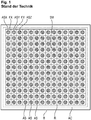
- an antigen chip AC known from the prior art with antigen spots AS for a recorded image area B for a first color channel or first dye is shown as an example.
- a grid R to be generated or recognized is also shown.
- the chip AC carries a spot pattern SM. It is assumed that the antigen spot ASX carries a different antigen than the antigen spot ASY. The left, upper antigen spot ASX must therefore be in the upper left field FX of the grid, so that an assignment to a specific antigen can be made correctly.
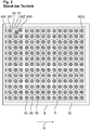
- the Fig. 2 shows a configuration in which there was no exact or no exact local arrangement of the spots AS on the substrate of the chip AC.
- the spot ASX is therefore only partially present on the chip AC and in the image area B, so that the raster R per se could be detected, but the fields FX, FY can be misaligned with respect to the spots ASX, ASY.
- An assignment of an antigen type to the spot ASY on the basis of the grid field FX assigned to the spot ASY would therefore be faulty and then also a binding detection with regard to the binding of antibodies of the biological sample to a specific antigen.
- a method according to the invention for the automated detection of antibodies in a liquid biological sample using an antigen chip and a corresponding antigen chip according to the invention are therefore proposed.
- the antigen chip according to the invention has a flat substrate surface with antigen spots which are spaced apart from one another and have the same, common dye.
- This dye can also be referred to as a first dye.
- the antigen spots here form respective antigen spot amounts, which form respective, regular antigen spot patterns, antigen spots of the same antigen spot amount having the same, common type of antigen.
- two or more of the antigen spot amounts have different antigen types.
- the antigen chip according to the invention is characterized in that reference spots are also applied to the substrate surface, which also have the same, common dye.
- the reference spots form a reference spot quantity, which in turn forms a regular reference pattern, in particular along an arrangement direction in which the patterns follow one another.
- the regularity of the reference pattern differs from the antigen spot patterns or from the regularities of the antigen spot patterns.
- the antigen chip according to the invention is then used in the method according to the invention for the automated detection of antibodies in a liquid biological sample.
- the same, common dye can also be referred to as a first dye.
- the spots of the antigen chip are first incubated with the biological sample. Furthermore, the spots are incubated with a conjugate which has a secondary antibody labeled with a second dye.
- the bindings of the secondary antibodies and thus also of the second dye described above can result at certain antigen spots, depending on the type of antigen of an antigen spot and depending on the primary antibody contained in the sample.
- first image information is then acquired or provided, which represents a coloring of the reference spots and the antigen spots by the first dye.
- the reference pattern and a reference position associated with the reference pattern are then detected on the basis of the at least first image information. Furthermore, on the basis of the at least one first piece of image information, the respective antigen spot patterns and the respective associated further positions are then detected. Furthermore, on the basis of the detected reference position and the detected further positions, assignment information is created which indicates an assignment of the respective antigen spot patterns to respective antigen types. Finally, second image information is captured or provided, which represents a potential coloring of the antigen spots by the second dye. Finally, on the basis of the second image information and the assignment information, a determination of the respective binding measures is carried out, which indicate the respective binding of antibodies of the biological sample to the respective antigen types.
- the reference pattern and the antigen pattern are arranged along a direction of arrangement of the patterns, furthermore in particular the reference pattern and the antigen pattern have respective directions of propagation which are essentially perpendicular to the direction of arrangement of the patterns.
- the reference pattern and the antigen spot patterns preferably have respective directions of propagation which run perpendicular to an arrangement direction of the patterns.
- the directions of propagation of the patterns preferably run essentially parallel to one another.
- the antigen spots and the reference spots have the same, common dye which is visible in a first color channel, which is preferably a so-called red channel.
- the antigen chip according to the invention and the method according to the invention achieve one or more of the advantages now mentioned below, for which detailed explanations follow below.
- the antigen chip has reference spots, which form their own regular reference pattern, which differs in its regularity from the antigen spot patterns of the antigen spots, it is possible to determine a position or location of the reference Pattern to be detected in the first color channel or the first image information. Since the antigen spot patterns differ in their type of pattern or their regularity from the reference pattern, the antigen spot patterns can be detected separately with regard to their position or position on the substrate surface. It can then be determined which of the antigen spot patterns has which antigen types, since the reference position of the reference pattern in relation to further positions of the further antigen spot patterns indicates from where or from which position trace a sequence of the antigen spot patterns in an arrangement direction of the patterns on the substrate surface.
- a specific antigen spot pattern with a specific type of antigen need not therefore be arranged at a very specific point on the image or on the substrate surface. Rather, it is sufficient that an antigen spot pattern is arranged in a specific position relative to the reference position of the reference pattern along an arrangement direction of the patterns.
- An assignment information item, which indicates an assignment of respective antigen spot patterns to respective antigen types, can then be made, for example, by providing a data record which assigns such an assignment depending on a position of the antigen spot pattern indicates a position of the reference pattern.
- the method according to the invention particularly robust, since it is only necessary to arrange the antigen spots of a specific antigen spot quantity as an antigen spot pattern in such a way that the corresponding pattern is sufficiently different from other patterns, for example, in its position.
- the antigen spots do not form their own regular patterns, but are arranged in a kind of checkerboard process at a wide variety of positions, with an assignment of a specific antigen type to spots being very sensitive to the individual alignment of the spots on the substrate surface or a picture.
- the antigen chip according to the invention is particularly advantageous because, as described above, it is only a matter of the sequence of the reference pattern and the antigen spot patterns in the arrangement direction or along the arrangement direction of the patterns on the substrate surface, so that the reference pattern and the further antigen spot patterns merely in an orderly sequence on one another along the arrangement direction must occur.
- This has particular advantages in the course of a production process, since when the entirety of the patterns is applied in a periodic, repetitive or repetitive manner, so that the entirety of the patterns is repeated periodically one after the other, the substrate carrier is not subsequently separated or exactly at that point. must be fragmented, on which the entirety of the patterns is repeated in order to produce several antigen chips, each with the entirety of the patterns.
- antigen spot quantities or antigen spot patterns and the reference pattern or reference spot quantity each occur at least once on the antigen chip to be produced.
- Such an entirety of the patterns or such a sequence of these antigen spot patterns and the reference pattern usually results over a predetermined distance along the direction of arrangement of the patterns on the substrate carrier.
- this distance does not have to be kept exactly, but it is sufficient if the repetition distance of the entirety of the patterns along the arrangement direction of the patterns during the production of the antigen chip is not only undercut.
- the substrate surface can also be separated or fragmented after a distance along the arrangement direction which is greater than the repetition distance of the entirety of the patterns in the arrangement direction, within which all different patterns are contained at least once.
- the distance between two fragmentation sites is greater than the repetition distance of the entirety of the patterns and furthermore also less than twice the repetition distance of the entirety of the patterns.
- the separation or fragmentation takes place in particular in a direction perpendicular to the direction of arrangement of the patterns.
- the antigen chip according to the invention and the method according to the invention are also advantageous since a slight misalignment of individual spots within a certain pattern is an effect to which the method according to the invention reacts less sensitively than the solution according to the prior art, in which all spots are in one clearly defined and rigid pattern with the same distances between all neighboring spots.
- the antigen chip according to the invention it is just possible that when the patterns are arranged along an arrangement direction in succession on the substrate surface, a spacing of the patterns from one another between different patterns can also be designed differently.
- the patterns in the method according to the invention are recognized or detected, for example, by the fact that the regularity of a pattern consists of the spots of a corresponding spot quantity or of a relevant spot pattern being a certain distance apart on average to each other, a next, adjacent pattern to the previous pattern can have a neighboring distance, which can be different from another neighboring distance between other patterns. Nevertheless, the method according to the invention can still robustly identify corresponding positions of the patterns by image analysis of the antigen chip according to the invention and assign the respective spots to the respective antigen types.
- the regularity of the reference pattern differs from the regularity of the antigen spot pattern in that the pattern, that is to say the reference pattern, as well as the antigen spot Patterns, have a common regularity parameter, the value of which differs in the reference pattern from the values of this regularity parameter of the antigen spot pattern.
- the same common dye is preferably a fluorescent dye, which can also be referred to as the first fluorescent dye.
- the same, common dye is a chromogenic substrate which, for the purpose of chromogenic staining, can bind to an enzyme which in turn is contained in a conjugate, by means of which the spots of the antigen chip can be incubated.
- the second dye is preferably a fluorescent dye, which can be referred to as a second fluorescent dye.
- the respective fluorescent dyes can be excited by irradiating excitation light of respective different excitation wavelengths or the same excitation wavelength to emit respective fluorescent radiation of respective different fluorescence wavelengths.
- the excitation light wavelengths for the two fluorescent dyes can overlap or be identical.
- the antigen chip is preferably characterized in that the same common dye is a fluorescent dye.
- the antigen chip is preferably characterized in that the second dye is a fluorescent dye.
- the antigen chip is characterized in that the reference spots of the reference spot quantity form a reference line pattern and that the respective antigen spots of the respective antigen spot quantities form respective antigen line patterns.
- the distance of the antigen spots from one another within a pattern for at least one of the patterns differs from a spacing distance or neighboring distance of the pattern from an adjacent pattern in the arrangement direction of the patterns.
- the antigen chip is preferably characterized in that the reference spots also have an antigen.
- the antigen chip is preferably characterized in that the reference spots also have an antibody, in particular IgG.
- the binding dimensions are preferably output, in particular in the form of a data element, which is output in particular via a data interface.
- the first image information is preferably received via at least one data interface and is provided by means of at least one storage unit, and the second image information is preferably also received via the data interface and by means of the Storage unit provided.
- the first image information preferably represents a coloring of the reference spots and the antigen spots of the antigen chip by the first fluorescence radiation.
- the second image information preferably represents a potential coloration of the antigen spots of the antigen chip by the first fluorescent radiation.
- the first excitation light and the second excitation light preferably have the same excitation wavelength.
- the device also has at least one illumination unit for emitting excitation light for exciting an emission of first fluorescent radiation of a first wavelength range through the first dyes.
- the device also has at least one illumination unit for emitting excitation light for exciting an emission of second fluorescence radiation of a second wavelength range through the second dye.
- the proposed device for the automated detection of antibodies of a sample preferably has at least one computing unit, which is further configured to carry out further steps which are disclosed above with reference to the method for automated detection of antibodies and / or the method for automated image processing or have been described.
- a data network device for automated image evaluation for detecting antibodies in a sample is also proposed.
- the data network device is preferably a so-called cloud system.
- the data network device has at least one data interface which is designed to receive first image information which represents a coloring of reference spots and of antigen spots of an antigen chip according to the invention according to one of the embodiments proposed here by a first dye.
- the data interface is also designed to receive second image information, which shows a potential coloring of the antigen spots of the antigen chip according to the invention according to one of the embodiments proposed here by a second dye after incubating the antigen chip with the biological sample and with a conjugate which has a secondary antibody labeled with the second dye.
- a data carrier signal that transmits the computer program product is also proposed.
- the data carrier signal can be provided, for example, in the form of data packets, in particular IP packets.
- the data signal is a download data signal for the transmission of software, in particular a software application.
- a slide is also proposed which has a multiplicity of antigen chips according to the invention in accordance with one of the embodiments described here.
- the production method preferably further comprises the step of fragmenting the substrate in order to obtain a plurality of antigen chips, in particular at two fragmentation sites whose spacing from one another is greater than a width of the substrate, within which the entirety of the reference pattern and antigen pattern is present.
- the substrate surface is preferably a surface of a glass substrate or a glass substrate coated with a membrane and / or film.
- the application of the antigen spots can be carried out by means of a piezoelectric microdosing device, and the substrate surface can in particular be a surface of a glass substrate or a glass substrate coated with a membrane and / or film. This means that production can be carried out using conventional basic materials and production machines.
- kits for use in a method for detecting antibodies in a liquid, biological sample which has an antigen chip according to the invention according to one of the embodiments described here, and further a conjugate which has a secondary antibody labeled with a second dye.
- the second dye is preferably a fluorescent dye, a chromogenic substrate, an enzyme or a substrate for a chemiluminescence reaction.
- the chip can be viewed as a solid substrate, such as a glass plate or, for example, silicon plate.
- the chip can also be made of plastic or metal.
- the chip can be translucent or non-translucent to support transmitted light or incident light illumination or detection.
- the antigen chip can be used in a scanner or camera system, in particular a fluorescence microscope, to examine a sample and can then be irradiated with illuminating light or excitation light.
- the substrate surface is microstructured for focusing.
- the microstructuring can be carried out by a surface treatment (for example roughening) and can facilitate focusing on the substrate surface.
- a surface treatment for example roughening
- Various processes for microstructuring such as injection molding, hot stamping or imprint processes, are known in the prior art.
- Various microstructure markers can be applied to the surface, which can also be used to identify the antigen chip, to identify the sample, etc.
- the antigen substrate (the chip) comprises in particular an area with a size between 1 mm x 1 mm and 2 mm x 4 mm.
- chemiluminescence refers to a chemical reaction in which energy is specifically directed to a molecule, causing it to be electronically excited and then to release a photon, thereby emitting visible light. Thermal energy is not required for this reaction. Chemiluminescence therefore involves the direct conversion of chemical energy into light energy. Chemiluminescence is preferably produced by the reaction of a luminophore with other compounds. These reactions can be catalyzed by enzymes. In further preferred embodiments of the invention, the luminophore is selected from the group consisting of luminol and derivatives thereof, acridine and derivatives thereof and luciferins. These compounds can be stimulated to chemiluminescence by various enzymatic reactions.
- the luminophore is luminol or a derivative thereof, light being emitted by a reaction catalyzed by peroxidase, in particular horseradish peroxidase (chemiluminescence).
- the luminophore is Acridine or a derivative thereof, in particular an acridinium ester or acridinium sulfonamide, light being emitted by a reaction catalyzed by phosphatase, in particular alkaline phosphatase (AP) (chemiluminescence).
- the luminophore is a luciferin, in particular D-luciferin, light being emitted by a reaction catalyzed by luciferase (chemiluminescence).
- a "chromogenic substrate”, in the sense of the present invention, is a reagent that can be used to measure enzyme activities.
- the chromogenic substrate is changed by enzymatic activity so that a direct or indirect product of the enzymatic reaction can be quantified (photometrically).
- the chromogenic substrate is e.g. from an oligopeptide to which an azo dye, for example paranitroaniline, is coupled.
- the peptide mimics the interface at which the enzyme under investigation cleaves its physiological substrate.
- the dye is released by the enzyme action.
- the color development can be quantified photometrically and the enzyme activity can be determined using a calibration curve.
- the chromogenic substrate can also be 5-bromo-4-chloro-3-indoxyl phosphate (BCIP) and / or nitro blue tetrazolium chloride (NBT).
- a chromogenic substrate can e.g. be detected colorimetrically.
- the antigens contained in the various antigen spots can be selected and designed to bind antibodies that form as a result of autoimmune diseases, allergies and infectious diseases. In the present test system, this relates in particular to antinuclear and / or extractable antinuclear antibodies from the field of collagenosis.
- the following antigens can be contained in the antigen spots: RNP / Sm, Sm, Scl-70, Rib.P0, Jo-1, SS-A, SS-B, dsDNA, nucleosomes / Chromatin, Cenp-B, RNP A, C, 68kDa, Ro-52, Ku, Histone, DFS70.
- the diagnosable collagenoses can contain at least one of the following forms: SLE (Systemic lupus erythematosus), PM, DM (Myositis), SS (Sjögren's Syndrome), CREST syndrome (limited cutaneous form of systemic sclerosis lcSSc), PSS (progressive systemic sclerosis) , MCTD (mixed connective tissue disease, sharp syndrome), AID (autoimmune induced disease). It can be used to diagnose various diseases.
- antigen chips with spots of different antigen types in a kind of checkerboard pattern.
- an antigen chip AC as in FIG Fig. 2 has an alignment of antigen spots AS which does not match a raster to be used later, which is used to assign the spots AS to corresponding antigen types on the basis of their exact position, so that detection of binding of antibodies to a liquid sample certain types of antigen can be carried out by evaluation in a so-called second color channel.
- the Fig. 3a shows an exemplary embodiment of an antigen chip A, in which antigen spots AS in antigen spot patterns AM are applied spaced apart from one another on a substrate surface SO, the antigen spots AS having the same, common dye or first dye.
- the antigen spots form respective antigen spot quantities AG, which in turn form respective regular antigen spot patterns AM.
- the antigen chip A also has a reference pattern RM with reference spots which have a spot distance SD1 from one another.
- the spot distance SD2 of the antigen spots of the antigen spot pattern AM is different from the spot distance SD1 of the reference pattern RM.
- the regularity parameter of the pattern RM, AM is the respective spot distance SD1, SD2 within the respective pattern RM or AM.
- the reference pattern RM thus differs from the antigen spot patterns AM in terms of the value of this regularity parameter or in terms of its regularity.
- the patterns RM, AM are arranged along an arrangement direction ANR.
- the patterns RM, AM each have a direction of propagation ABR which is perpendicular to the direction of arrangement ANR of the patterns AM, RM.
- the spots of the pattern RM, AM have the same, common dye.
- the antigen spots of the antigen spot pattern AM1 have the same, common antigen or a same, common antigen type which differ from an antigen type or an antigen of the pattern AM2.
- an antigen chip A is incubated with all its spots of the pattern RM, AM with a biological sample such as a blood serum, then it can be for the spots of the different antigen spot patterns AM1, AM2 due to the different antigen types of the pattern AM1, AM2 come to differently strong binding of antibodies from the biological, liquid sample to the respective antigen types.
- Such a binding is a so-called first antibody from the biological, liquid sample which is then to be detected later.
- the antigen chip A preferably has a further, second reference pattern RM2, which matches its reference spots with regard to its regularity or its Value of the regularity parameter differs from both the first reference pattern RM and the antigen spot pattern AM. This is the case since the reference pattern RM2 has a spot distance SD3, which clearly differs from the spot distances SD1, SD2.
- the common, identical dye of the spots of the patterns RM, RM2, AM is preferably visible in a first color channel as a red channel.
- the regularity of the reference pattern RM differs from the antigen spot patterns AM and in particular also the second reference pattern RM2 by a variation of a common regularity parameter of the patterns RM, AM and in particular RM2.
- a regularity can also be referred to as a periodicity of a pattern, the regularity parameter being a periodicity parameter. Differing spot patterns then have different values with regard to the same regularity parameter of the spot patterns.
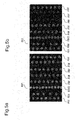
- the 5a and 5b show a first image information BI2 or a second image information BI2 with respective colorations in different color channels by respective dyes.
- the first image information BI1 shows an exemplary reference pattern RM and an exemplary and preferably present second reference pattern RM2 in the first color channel due to a coloring of the first dye. Furthermore, antigen spot patterns AM are visible in the first image information BI1 due to the coloring by the first dye in the first color channel.
- a presumed sequence of antigen types in the arrangement direction ANR with respect to the individual antigen spot patterns AM can be corrected when the in Fig. 3a shown antigen chip A is rotated by 180 °.
- Such an undesired rotation of the antigen chip A can then be detected in image information of the first color channel by the position of the first reference pattern RM and the second reference pattern RM2 relative to one another and thus the position or the position of the antigen spot patterns Correct the assumed arrangement direction ANR even in the event of an undesired 180 ° rotation of the antigen chip.
- the first dye is preferably a fluorescent dye.
- the first dye is a chromogenic substrate which, for the purpose of chromogenic staining, can bind to an enzyme which can be added by a further conjugate in the course of a further incubation of an antigen chip.
- the discoloration due to a binding of the chromogenic substrate with an enzyme it can be regarded as a discoloration product that can be detected photometrically.
- the second image information BI2 from the Fig. 5b shows that a staining in the second color channel is not significantly present for all antigen spot patterns AM due to the second dye. This is presumably the case since there was no significant or significant binding of antibodies of the liquid, biological sample to the corresponding antigen types of the corresponding antigen spot pattern, so that when the antigen chip is incubated with a second conjugate, which contains a second antibody with a label by the second dye, then the second antibodies were not bound to first antibodies from the liquid biological sample.
- the second dye is preferably a fluorescent dye.
- the second fluorescent dye is preferably a chromogenic substrate which can bind to an enzyme, the enzyme being able to be contained in a conjugate which can be used for incubating the spots in a further processing step.
- the enzyme then enters a discoloration product with the chromogenic substrate, which can be detected photometrically.
- the second dye is preferably an enzyme, so that when the spots are incubated with a conjugate which has a chromogenic substrate, the enzyme binds to the chromogenic substrate in order to produce a discoloration product which can be detected photometrically.
- the second dye is preferably an enzyme which can bind or interact in the course of a further processing step by incubating the spots with a conjugate which has a further substrate, so that radiation is emitted due to a chemiluminescence reaction.
- the second dye is preferably a substrate for a chemiluminescence reaction, so that when the spots are incubated with a conjugate which has an enzyme which in turn can react with the substrate, the chemiluminescence reaction will occur, so that chemiluminescence radiation is emitted.
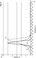
- fluorescent radiation FL can be generated by an excitation light AL1 or AL2, as in FIG Fig. 6 shown to be excited.
- the fluorescent light FL is preferably the light which is emitted by the first fluorescent dye.
- the axes of the in the representation of the Fig. 6 show the wavelength WL on the abscissa and the intensity IN on the ordinate.
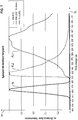
- the axes of the in the representation of the Fig. 7 show the wavelength WL on the abscissa and the intensity IN on the ordinate.
- the Fig. 7 shows in a diagram with a wavelength WL on the abscissa and an intensity IN on the ordinate a spectrum of an excitation light AL, a spectrum FL1 of a first fluorescent radiation by a first fluorescent dye and a spectrum FL2 of a second fluorescent radiation by a second fluorescent dye.
- the first fluorescence FL1 can comprise emission of light in a first wavelength range and the second fluorescence FL2 can comprise emission of light in a second wavelength range, the first wavelength range and the second wavelength range having only a slight or essentially no overlap range, for example an overlap range or an overlap which, for example, corresponds to less than 10%, in particular less than 5%, of an integral of an emission of the first fluorescence over the wavelength.
- the first fluorescent dye can fluoresce, for example, in a red wavelength range, for example in a range between 550 nm and about 800 nm with a maximum between 600 nm and 660 nm.
- the first fluorescent dye can be the dye DY521XL.
- the excitation of the first fluorescent dye can take place in a frequency range, for example between 450 nm and 500 nm, with a maximum, for example between 550 nm and 580 nm.
- the excitation of the second fluorescent dye can take place essentially in the same wavelength range as the excitation of the first fluorescent dye.
- the second fluorescent dye can fluoresce, for example, in a green wavelength range, for example in a range between 500 nm and about 600 nm with a maximum between 510 nm and 530 nm.
- the first fluorescent dye can be the dye FITC.
- a single illuminating light source is required to generate the excitation light, which can be designed in a relatively narrow band.
- the reference spots of the reference spot amount RM can have the dye in a dye concentration which is greater than the dye concentrations in which the antigen spots or the antigen spot quantities or antigen spot pattern AM and in particular also the reference pattern RM2 have the first dye or the same common dye.
- the second reference pattern RM2 can also preferably have this same, common dye in a dye concentration which is greater than the dye concentrations in which the antigen spots of the antigen spot amounts AM have the same, common dye.
- the spots of the reference spot amount RM - and in particular also of the second reference spot amount RM2 - had the same, common dye in a higher dye concentration, this could enable detection of the reference pattern RM - and in particular also of the rest Reference pattern RM2 - can be facilitated in the course of automated image processing, since the color intensities of these spots in image information would be greater than that of the antigen spots of the antigen spot amounts.
- the reference pattern RM forms a reference line pattern and that furthermore the antigen spot patterns AM also form reference line patterns, the lines of the patterns RM and AM having the same direction of propagation.
- the reference pattern RM2 likewise forms a reference line pattern. This can also be referred to as a further or second reference line pattern.
- the respectively associated spots of these patterns follow one another essentially at regular, preferably essentially equidistant intervals, the regular, preferably essentially equidistant, distance of the reference spots of the reference line pattern RM from the regular, preferably essentially equidistant distances of the antigen spots of the antigen line pattern AM differs.
- this pattern RM2 differs both from the first reference pattern RM and from the antigen line patterns AM in that the associated spots of the pattern RM2 differ distinguish their regular, preferably substantially equidistant, distance from the regular, preferably essentially equidistant, distances of the antigen spots of the antigen line pattern AM and of the spots of the first reference pattern RM2.
- the Fig. 3b shows a preferred variant A2 of an antigen chip A2 according to the invention, in which only three antigen spot patterns AM1, AM2, AM3 are present on the antigen chip A2. This is a subset of patterns that are already in this arrangement on the antigen chip A from the Fig. 3a available.
- the patterns RM, RM2, AM are arranged in an arrangement direction ANR.
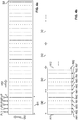
- the Fig. 4a shows a substrate or a substrate surface SU.
- the substrate surface SU is preferably a surface of a glass substrate or a glass substrate coated with a membrane and / or film.
- Different patterns RM, RM2, AM are to be applied to the substrate on the substrate SU along an arrangement direction ANR.
- the spots of the respective patterns RM, RM2, AM are applied to the substrate SU by means of respective pipettes P.
- the pipettes P can in this case be stationary, so that the respective droplets T, the pipettes P apply respective spots for a respective spot quantity, preferably as a line pattern, to the substrate surface SU, the substrate SU thus facing the pipettes P in a feed direction VR1 can be postponed that the aforementioned regular patterns develop.
- the reference spots of the reference spot quantity RM thus form a reference line pattern and the antigen spots of the respective antigen spot quantities AM form respective antigen line patterns.
- a new set of corresponding reference patterns RM, RM2 and antigen spot patterns AM can then be formed by displacing or advancing the substrate support SU in the feed direction VR2 by the distance DI1, in which case the substrate carrier SU is in turn also advanced in the feed direction VR1 in order to bring about a relative movement of the substrate carrier SU with respect to the pipettes P.
- the corresponding pipettes P In order to form the corresponding line patterns RM, RM2, AM with different regular intervals of their respective spots, the corresponding pipettes P only have to be activated in such a way that the drops T are formed with different frequencies or different intervals along the feed direction VR1 , Forming the patterns RM, RM2, AM as a line pattern allows a particularly effective production of the antigen chip according to the invention. Patterns for several antigen chips can then be produced in serial processing on the substrate carrier SU and so a separate substrate carrier SU does not have to be used for each antigen chip.
- the application by the pipette heads is carried out in particular by a so-called piezo pressure using a piezoelectric microdosing device as a special embodiment of the pipettes P. It can thus be stated that application of reference spots and antigen spots to the flat substrate surface SU in this way is carried out that an antigen chip results according to the previously described embodiment.
- the Fig. 4b now illustrates a particular advantage of the antigen chip according to the invention.
- the substrate surface from the Fig. 4a could be fragmented exactly in such a way that the substrate SU is always fragmented exactly according to the distance DI1 parallel to the direction of propagation of the patterns, that is to say perpendicular to the arrangement direction ANR of the patterns.
- a position of the reference pattern RM and the antigen spot pattern AM on the different antigen chips to be produced in this way would then always result in the same, repeating position or position on the corresponding antigen chip. Due to the inventive design of the antigen spot pattern AM and the reference pattern RM and in particular the second reference pattern RM2, however, as in FIG Fig.
- the distance DI2 which can only be selected approximately, so that corresponding antigen chips A11 and A12 result from the Fig. 4b can result. It is essential that the distance DI2, after which the substrate carrier SU is fragmented, is at least as large as the distance DI1 or larger than this distance DI1.
- the distance DI2 to be selected also only has to be less than twice the distance DI1 in order to avoid a complete repetition of all the patterns AM, RM, RM2.
- the sequence of the corresponding antigen types can be compared to the antigen spot patterns AM1, AM2, AM3 due to the distinguishability of these patterns the reference pattern RM and in particular the reference pattern RM2 are used in the course of an automated image evaluation in order to detect binding of antibodies for at least each antigen type or each of the antigen spot patterns AM1, AM2, AM3.
- the subsequently produced antigen chip A12 then has at least each type of an antigen spot pattern AM1, AM2, by choosing the fragmentation distance DI2 versus the repetition distance DI1 of the antigen spot pattern and the reference pattern and in particular the second reference pattern.
- the reference spots RM of the reference pattern can also also preferably still have an antigen, so that binding of antibodies of the biological sample, to which in turn second antibodies of a conjugate can be bound by labeling with a second dye, can then be detected and thus a further, additional type of antigen can be used with regard to detection of antibodies in the biological sample.
- the reference spots of the reference pattern RM and, in particular, of the reference pattern RM2 preferably have antibodies, in particular in the form of anti-human IgG.
- Such an antibody can then bind to an antibody of a liquid patient sample, for example a blood serum, so that after further incubation of the reference spots with a conjugate, which in turn can have a second antibody labeled with a second dye, binding of the second Dye is given to the reference spots.
- a conjugate which in turn can have a second antibody labeled with a second dye
- binding of the second Dye is given to the reference spots.
- the reference spots RM, RM2 can thus be used as an incubation control.
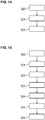
- Fig. 13 shows again steps of the proposed manufacturing process.
- step S100 a substrate with a flat substrate surface is provided.
- step S101 reference spots are applied to the flat substrate surface.
- step S102 antigen spots are applied to the flat substrate surface.
- the antigen spots and the reference spots are applied in order to obtain an antigen chip according to one embodiment in FIG previously described manner.
- step S103 which is preferably to be carried out, the substrate is fragmented in order to obtain a plurality of antigen chips. The fragmentation is carried out while maintaining a distance between two fragmentation sites, which is at least as great as a distance in a repetitive sequence of antigen spot patterns and reference spot patterns, which describes this repetitive sequence in an arrangement direction of the patterns.
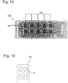
- the Figure 18 a slide OT, which has several antigen chips A in different fields FE.
- Fig. 19 shows a detailed representation of a single field FE with several antigen chips A.
- the antigen spot pattern AM and the reference pattern RM can differ in that they have a different periodicity or a different regular spacing of antigen spots from one another.
- This formation of the antigen spot pattern AM and the reference pattern RM is illustrated here in this manner only by way of example.
- the differentiation of the reference pattern RM, in particular also the second reference pattern RM2, from the antigen spot patterns AM consists in the fact that the reference pattern RM along the arrangement direction ANR has such an immediate neighbor to a next immediately adjacent pattern. Has a distance that differs from the other neighboring distances of the antigen spot pattern AM.
- the patterns RM, AM need not have different regular distances between their respective spots within the patterns RM, AM, but can differ based on a distance or a neighboring distance to the next pattern in or along the arrangement direction ANR.
- the reference pattern RM and in particular also the second reference pattern RM2
- the size of the spots of the reference pattern RM differing from the sizes of the antigen Spots of the antigen spot pattern AM differs.
- the reference pattern RM and the antigen spot pattern AM can differ in that spots of different sizes are formed for the different respective patterns RM, AM, which in the course of a manufacturing process, as in FIG Fig. 4a illustrated, for example by different pipette sizes to generate different ones Sizes of spots or different sizes of drops can be used to form the spots.
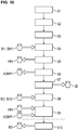
- the Fig. 10 shows preferred steps of a method according to the invention for the automated detection of antibodies in a liquid biological sample.
- step S1 an antigen chip is provided according to one of the previously described embodiments.
- the spots of the antigen chip are incubated with the biological sample.
- the spots are incubated with a conjugate which has a secondary antibody labeled with a second dye.
- the first piece of image information BI1, BI11 is provided or recorded, which represents a coloring of reference spots and of antigen spots of the antigen chip by a first dye.
- the antigen chip is preferably illuminated in step S4 with a first excitation light of a first wavelength to excite an emission of first fluorescent radiation by the first dye.
- the first image information then represents a coloring of the reference spots and the antigen spots of the antigen chip by the first fluorescence radiation. This is preferably done in a so-called red channel.
- a step S5 the reference pattern and an associated reference position on the substrate surface are detected assuming an arrangement direction of the patterns on the substrate surface on the basis of the at least first image information.
- the reference position can be provided as reference position information RPI.
- a step S6 the respective antigen spot patterns and the respective associated further positions on the substrate surface are detected assuming an arrangement direction of the patterns on the substrate surface on the basis of the at least first image information. This can be provided as so-called further, total position information AGMPI in relation to the further positions of the antigen spot patterns.
- an assignment information item ZI is then created on the basis of the detected reference position and the detected further positions, which indicates an assignment of the respective antigen spot patterns to the respective antigen types.
- second image information BI2, BI12 is then acquired, which provides a potential coloration of the antigen spots and preferably the reference spots are also represented by the second dye.
- the antigen chip is preferably illuminated with a second excitation light of a second wavelength in order to excite an emission of second fluorescent radiation.
- the second excitation light of the second wavelength is preferably identical in its wavelength range to the wavelength range of the first excitation light for exciting the first fluorescent radiation of the first fluorescent dye.
- the second image information then preferably represents a potential coloring of the antigen spots of the antigen chip by the second fluorescent radiation.
- a step S9 preferably using the reference position information RPI and the further position information AGMPI, it is then possible to determine the respective binding measures, which respective bonds or degrees of binding of antibodies of the biological sample to the respective antigen type medicine, on the basis of the second Image information BI2, BI12 and the assignment information ZI take place.
- binding measures can preferably be output in a method step S10, preferably in the form of a data element BD via a data interface.
- Steps S4 to S9 can preferably be carried out in the method according to the invention for automated image processing for detecting antibodies in a liquid biological sample according to one embodiment.
- step S10 which is preferably to be carried out.
- step S10 information is therefore preferably provided via a data interface, which indicates the position of the pattern and preferably also the position of individual antigen spots and individual reference spots on the antigen chip.
- step S7 The assignment of antigen spot patterns to respective antigen types in step S7 is preferably carried out in a manner as in FIG Fig. 11b illustrated.
- a spatial sequence of the reference position of the reference pattern and the respective further positions of the respective further antigen spot patterns is determined. This position can also be referred to as positions along an, in particular assumed, arrangement direction of the patterns on the substrate surface.
- a sequence data record ADS is provided, which indicates a sequence of antigen types.
- this is a spatial sequence of antigen types along an arrangement direction of patterns.
- the Fig. 11c illustrates an exemplary sequence data record ADS, which indicates corresponding antigen types AT1, AT2, AT3 in corresponding fields AT for a sequence of patterns along an arrangement direction ANR for successive positions in corresponding fields PN.
- the sequence data record ADS thus indicates a spatial sequence of respective antigen types for respective positions along an arrangement direction ANR of spot patterns.
- Corresponding reference pattern types R1, R2 are also specified in corresponding fields RT for specific positions. In this preferred embodiment, a first and a second reference pattern are present. It is understood by the person skilled in the art that only one reference pattern type R1 is present in the case of only one reference pattern.
- An assignment information item ZI is then created, which indicates the assignment of the respective antigen spot patterns to the respective antigen types. This is done on the basis of the detected reference position, the detected respective further position of the respective antigen spot pattern and the sequence data record ADS.
- a further reference position of a second reference pattern is preferably also detected in the course of the method and taken into account in the course of the assignment of the respective antigen spot patterns to the respective antigen types. This enables compensation or consideration of an undesired 180 ° rotation of the antigen chip.
- step S5A the second reference pattern and an associated second reference position are then detected in step S5A on the basis of the first image information.
- step S6 described above then follows.
- step S7A the assignment information ZI is then created, which indicates the assignment of the respective antigen spot patterns to the respective antigen types. This is done on the basis of the detected first reference position, the detected second reference position and the detected further position of the respective antigen spot pattern and preferably also of the sequence data set.
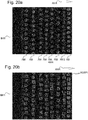
- the 20a shows a first reference pattern RM, a second reference pattern RM2 and antigen spot pattern AM represented by first image information BI11 in a first color channel, which is preferably a red channel.
- the Fig. 20b shows in the first image information BI11 corresponding exemplary antigen spot positions AGSPI1, which are shown as rectangles.
- AGSPI1 exemplary antigen spot positions
- RM, RM2 from the 20a the individual spots can then be assigned to individual patterns AM, RM, RM2, in particular line patterns.
- respective positions along the arrangement direction ANR can be determined for respective patterns AM, RM, RM2.
- individual antigen spot patterns can be assigned to individual antigen types, preferably on the basis of a sequence data set.
- the Fig. 21a shows a coloring of spots by a second dye of the same antigen chip as from the 20a and 20b .
- the Fig. 21a shows a second image information BI12, which represents a coloring of spots, in particular the antigen spots by the second dye and thus in a second color channel, preferably a green channel.
- a number of potential patterns are then identified on the basis of the at least first image information.
- a respective regular average spot spacing of spots is then detected within a respectively recognized pattern for the respectively recognized, potential pattern.
- one of the recognized patterns is then selected as the reference pattern on the basis of the detected mean spot distances. As can be seen by a person skilled in the art, this can also be carried out for the second reference pattern.
- Fig. 15 preferably steps to be performed.
- a step S30 circular objects are identified in the first image BI11 by means of a Hough transformation.
- step S31 extraction of properties for the identified circular objects, such as e.g. a contour and / or intensity properties.
- the properties can be a circumference of a circle, a deviation from a perfect free circle or the average intensity of an object.
- a step S32 the proposed circular objects from the Hough transformation with their properties are then classified into a first class "spot” or a second class "image artifact” using a support vector machine. Only those image areas or objects that are classified as spots are used below.
- a position on the antigen chip or in the image information BI11 in the X or Y position can be determined or determined in step S31.
- spots can then be combined to form a pattern or a line pattern or a line.
- a list is created for the spots, which is sorted on the basis of their Y position in the image.
- a spot is taken from the list and its closest neighbor is found at a Euclidean distance. If both spots are at an angle of approximately 90 ° to one another or form a straight line which forms an angle of 90 ° with respect to the arrangement direction, it is assumed that they belong to the same pattern or the same line.
- This value of 90 ° can also be provided with a blur window of several plus-minus degrees. If the two spots in question do not belong to each other to a pattern or to such a straight line of approx. 90 ° to the arrangement direction of the patterns, the next spot sorted by distance or Y position is considered from the list. If it is no longer possible to assign spots from the list to the currently viewed pattern or the currently viewed line, a new pattern or a new line is started in a direction perpendicular to the arrangement direction of the patterns. With such a method, the spots are then iteratively assigned to respective patterns or respective lines.
- the patterns or line patterns are then numbered in a step S34. This is preferably done in such a way that the pattern or the line whose spots are at the greatest mean distance from one another are adopted as the reference pattern or as the reference line pattern.
- a second reference pattern is preferably adopted as that pattern or as the line in which the spots have the smallest mean distance from one another.
- BI12 can then be made on the basis of the second image information Fig. 21b for those spots which are assigned to a pattern or a line, the respective intensities or pixel intensities per spot in the second color channel are determined on the basis of a coloring by the second dye. This is preferably done as the median value of the intensities of a spot.
- a determination of an average intensity value of a pattern can be carried out in such a way that the median value of the median intensities of the spots of a pattern is determined. This median value is then a measure of binding, which indicates a binding or a degree of binding of antibodies from the biological sample to a specific type of antigen.
- the antigen spot position information AGSPI obtained previously from step S6 based on the first image information BI11 and the reference spots obtained in step S5 can be used to determine the binding dimensions on the basis of the second image information BI12 - Position information used as in the RSPI Fig. 16 shown.
- the detection of a reference spot pattern and the respective antigen spot pattern thus includes detection of individual spot positions and an assignment of spots or spot positions to the reference pattern and the respective antigen spot pattern.
- a threshold value provided via a data element which can be applied to the median intensity determined for a pattern or an antigen type, is preferably used to determine a binding measure. If the median intensity value of a pattern falls below the threshold value, it is assumed that there is no binding of antibodies at all. Only in the event that the median value of a pattern exceeds the predefined threshold value is a value output which indicates that there is binding of antibodies to the corresponding antigen types.
- the binding dimensions can be output via a data element, for which, as in Fig. 12 drawn in, a data record BD indicates an assignment of binding measures BM to corresponding antigen types AT.
- the data record BD can be a list, for example.
- a binding measure BM1 is then included for an antigen type AT1, and corresponding binding measures BM2, BM3 for corresponding antigen types AT2, AT3.
- the reference pattern to an immediately adjacent pattern along the arrangement direction of the patterns has such a neighboring distance that differs from the other neighboring distances of the antigen spot pattern.
- the Fig. 22a an embodiment A21, at which only has a reference pattern RM.
- the reference pattern RM has a neighboring distance DI11 to the next directly adjacent pattern AM1 in the arrangement direction ANR, which is greater than the neighboring distance DI12 of the other patterns AM1, AM2, AM3 to their closest neighboring ones in the arrangement direction ANR Patterns AM2, AM3, RM.
- detected spot positions of the reference spots and the antigen spots can be used, as previously described in detail, to assign the spots to respective patterns or line patterns, so that just a few patterns based on the first Image information BI11 can be recognized.
- respective neighboring distances DI11, DI12 between the patterns can then be determined, that is, for example, a neighbor distance for the reference pattern to the directly adjacent next pattern to the right of it in the direction of the arrangement direction ANR. If the reference pattern has a neighboring distance that differs from the neighboring distances of the antigen spot patterns, the referring pattern can be reliably detected and recognized.
- the respective associated spots have a respective, identical size, the size of the reference spots of the reference pattern being different Sizes of the antigen spots differ from the antigen spot patterns.
- Fig. 22b a preferred embodiment A22 of an antigen chip in which there is only one reference pattern RM.
- the reference spots of the reference pattern RM have the same size. This size differs of the same common size that the antigen spots of the antigen pattern AM have.
- detected spot positions of the reference spots and the antigen spots can be used, as previously described in detail, to assign the spots to respective patterns or line patterns, so that just a few patterns based on the first image information BI11 can be recognized.
- a property such as the circumference of the identified circle or circle object is then determined for each spot. This allows spots of the same size or size to be assigned to the same pattern. The pattern whose spots have the largest spot size on average compared to the other patterns can then be detected as the reference pattern.
- the Fig. 8 shows a device V1 according to the invention according to an embodiment for the automated detection of antibodies in a sample.
- the device V1 comprises a so-called microscope device.
- An antigen chip C can be viewed through a lens O by means of at least one camera K1, K2.
- the cameras K1, K2 can be referred to as image acquisition units.
- the structure from the Fig. 8 for the device V1 an explicit separation of two color channels or optical channels is provided before image information is acquired by separate image acquisition units K1, K2. It is obvious to the person skilled in the art that such a device can also be realized by exchanging optical filters over time, in that only a single image acquisition unit is provided, but the use of the different optical filters for different color channels means that the device was previously described respective image information that can be captured in the respective color channels.
- a fluorescence light source LQ emits an excitation light AL, which is filtered by means of an excitation light filter F1 so that an in Fig. 7 described excitation light spectrum AL is directed to the dichroic mirror SP1.
- the dichroic mirror SP1 then directs this excitation light AL towards the objective O, through which the excitation light then strikes the antigen chip C and its spots.
- the first and second fluorescent radiation emitted by the antigen chip C or the fluorescent dyes of the spots then pass through the objective O through the dichroic mirror SP1 to an optical filter F2 which blocks the excitation light AL or its spectrum and the fluorescent radiation of the first Color channel and also a second color channel transmitted.
- the fluorescence radiation then arrives at a further dichroic mirror SP2, which reflects fluorescence radiation from the first color channel or first fluorescence radiation to a first image acquisition unit or camera K1.
- the first fluorescence radiation from the incoming spectrum is preferably also filtered by an optical filter FR.
- the filter FR is in particular a red channel filter.
- the dichroic mirror SP2 transmits the second fluorescent radiation or light of the second color channel to a second image acquisition unit or camera K2.
- This radiation is preferably filtered again by a further optical filter FG, the optical filter FG being in particular a green channel filter.
- the first camera K1 then captures the first image information BI1 and makes it available to the computing unit R.
- the second image capture unit K2 then captures the second image information BI2 and makes it available to the computing unit R2.
- the first image acquisition unit and the second image acquisition unit as an example for at least one image acquisition unit are then designed to acquire first image information BI1, which is a coloring of reference spots and of antigen spots of an antigen chip C by a first dye, in particular a first dye Fluorescent dye.
- the at least one image capture unit K1, K2 is designed to capture second image information BI2, which shows a potential coloring of the antigen spots of the antigen chip by a second dye, in particular a second fluorescent dye, after incubation of the antigen chip with the biological sample and with a conjugate which has a secondary antibody labeled with the second dye.
- the computing unit R is in particular designed to carry out one or more of the steps S4, S5, S6, S7 and S9 described previously with reference to the method for the automated detection of antibodies and the method of automated image processing for the detection of antibodies Fig. 10 perform.
- the computing unit R controls the image acquisition units K1, K2 and the fluorescent light source LQ accordingly.
- the device V1 from in Fig. 8 also preferably has a data interface DS1, via which data elements DA can be received or sent.
- binding measures can be transmitted here via such data elements DA, and data elements which indicate a threshold value can also preferably be received.
- the device V1 thus has, with the fluorescent light source LQ, an illumination unit for emitting excitation light for exciting an emission of first fluorescent radiation of a first wavelength range by the first dyes. Furthermore, the light source LQ also represents at least one illumination unit for emitting excitation light for exciting an emission of second fluorescent radiation of a second wavelength range by the second dye.
- Fig. 17 shows preferred steps in the course of the described method for automated detection of antibodies and / or the method for automated image processing.
- BI12 takes place in the second color channel or the second image information Fig. 21a or 21b an identification of antigen spots using the antigen spot position information AGSPI or the further position information AGMPI. Furthermore, in the case that the reference spots also have an antigen, the reference position information is used RPI or the reference spot position information RSPI an identification of the reference spots.
- image areas or spots are assigned to specific patterns and thus also to specific antigen types in step S41.
- a step S42 an average intensity or median intensity of a pattern is determined in the second color channel or on the basis of the second image information.
- step S43 a data record TH is provided or received, which indicates a threshold value to be applied to median intensities.
- This threshold value is then applied in step S43 to the determined average intensities of the respective patterns.
- a determination of the respective binding dimensions for the respective pattern is then carried out.
- a step S44a which is preferably to be carried out, an indication is then given to the user, preferably by means of an optical display unit or preferably by means of a data element to be output via a data interface, in the event that the reference spots of the reference pattern are in the second color channel or the second image information does not have sufficient coloring or medium intensity.
- the binding dimensions are then output in step S45.
- the Fig. 9 shows an embodiment of a data network device V2 according to the invention, which can preferably also be referred to as a cloud system.
- the data network device V2 for automated image evaluation for the detection of antibodies in a liquid and biological sample has at least one data interface DS, via which data elements DA2 can be exchanged via a data network.
- the device V2 has at least one computing unit R2, which is preferably connected to the data interface DS via a data bus DB.
- the data network device V2 preferably has at least one memory unit MEM.
- the at least one data interface DS is designed to receive first image information that represents a coloring of reference spots and of antigen spots of an antigen chip by a first dye.
- the at least one data interface DS is also designed to receive a second image information which shows a potential coloring of the antigen spots of the antigen chip by a second dye after incubation of the antigen chip with the biological sample and a conjugate which is one with the second dye has labeled secondary antibodies.
- the computing unit R2 is designed to carry out the steps described above with reference to the method for automated image processing, in particular one or more of the steps S4, S5, S6, S7 and S9. Furthermore, the computing unit R2 is designed to carry out further steps of the method for automated image processing which are preferably to be carried out and which have been explained in detail above.
- the device V2 from the Fig. 9 is furthermore preferably designed to provide data elements DA2 via the data interface DS which represent information which indicates the respective binding measures of antibodies to the respective antigen types.
- the data interface DS is also designed to index positions of antigen spots and / or patterns and reference spots or reference patterns detected via data elements.
- the device V2 from the Fig. 9 automated image processing for detecting antibodies in a liquid biological sample takes place, in particular, in that the first image information is received via the at least one data interface DS and is provided by means of the at least one memory unit MEM, the second image information also being received via the data interface DS is and is also provided by means of the memory unit MEM.
- the device V2 is preferably designed to receive a data element via the data interface DS which indicates certain types of antigen to which binding measures are to be output. An evaluation is then preferably carried out for these specific antigen types indicated and also a transmission of a data element which indicates the binding measures of the corresponding specific antigen types.
- aspects have been described in connection with a device, it goes without saying that these aspects also represent a description of the corresponding methods, so that a block or a component of a device can also be understood as a corresponding method step or as a feature of a method step. Analogously, aspects that have been described in connection with or as a method step also represent a description of a corresponding block or details or feature of a corresponding device.
- exemplary embodiments of the invention can implement the computing units R, R2 in hardware and / or in software.
- a processing unit R, R2 mentioned here can be implemented here as at least one processing unit or else by a plurality of processing units in the network.
- the implementation can be carried out using a digital storage medium such as a floppy disk, DVD, Blu-Ray disc, CD, ROM, PROM, EPROM, EEPROM or FLASH memory, hard disk or other magnetic or optical memory are carried out, on which electronically readable control signals are stored, which can interact with a programmable hardware component or cooperate in such a way that the respective method is carried out.
- CPU Central Processing Unit
- ASIC Application-Specific Integrated Circuit
- IC Integrated Circuit
- SOC System on Chip
- FPGA Field Programmable Gate Array
- the digital storage medium can therefore be machine or computer readable.
- Some exemplary embodiments thus comprise a data carrier which has electronically readable control signals which are able to interact with a programmable computer system or a programmable hardware component in such a way that one of the methods described herein is carried out
- exemplary embodiments or parts of the exemplary embodiments of the present invention can be used as a program, firmware, computer program or Computer program product can be implemented with a program code or as data, wherein the program code or the data is or are effective to perform one of the methods or a part of a method if the program runs on a processor or a programmable hardware component.
Landscapes
- Health & Medical Sciences (AREA)
- Life Sciences & Earth Sciences (AREA)
- Immunology (AREA)
- Chemical & Material Sciences (AREA)
- Engineering & Computer Science (AREA)
- Hematology (AREA)
- Molecular Biology (AREA)
- Biomedical Technology (AREA)
- Urology & Nephrology (AREA)
- Physics & Mathematics (AREA)
- Analytical Chemistry (AREA)
- General Health & Medical Sciences (AREA)
- Biochemistry (AREA)
- General Physics & Mathematics (AREA)
- Pathology (AREA)
- Microbiology (AREA)
- Cell Biology (AREA)
- Food Science & Technology (AREA)
- Medicinal Chemistry (AREA)
- Biotechnology (AREA)
- Nuclear Medicine, Radiotherapy & Molecular Imaging (AREA)
- Chemical Kinetics & Catalysis (AREA)
- Clinical Laboratory Science (AREA)
- Optics & Photonics (AREA)
- Proteomics, Peptides & Aminoacids (AREA)
- Investigating, Analyzing Materials By Fluorescence Or Luminescence (AREA)
- Investigating Or Analysing Materials By The Use Of Chemical Reactions (AREA)
- Automatic Analysis And Handling Materials Therefor (AREA)
- Apparatus Associated With Microorganisms And Enzymes (AREA)
- Investigating Or Analysing Biological Materials (AREA)
Priority Applications (1)
| Application Number | Priority Date | Filing Date | Title |
|---|---|---|---|
| PL19180580T PL3591403T3 (pl) | 2018-07-06 | 2019-06-17 | Sposób zautomatyzowanego wykrywania przeciwciał w ciekłej próbce biologicznej z zastosowaniem chipu antygenowego |
Applications Claiming Priority (1)
| Application Number | Priority Date | Filing Date | Title |
|---|---|---|---|
| EP18182266.9A EP3591401A1 (fr) | 2018-07-06 | 2018-07-06 | Procédé de détection automatisée d'anticorps dans un échantillon biologique liquide à l'aide d'une puce à antigène et puce à antigène correspondante |
Publications (2)
| Publication Number | Publication Date |
|---|---|
| EP3591403A1 true EP3591403A1 (fr) | 2020-01-08 |
| EP3591403B1 EP3591403B1 (fr) | 2021-01-20 |
Family
ID=62904286
Family Applications (2)
| Application Number | Title | Priority Date | Filing Date |
|---|---|---|---|
| EP18182266.9A Withdrawn EP3591401A1 (fr) | 2018-07-06 | 2018-07-06 | Procédé de détection automatisée d'anticorps dans un échantillon biologique liquide à l'aide d'une puce à antigène et puce à antigène correspondante |
| EP19180580.3A Active EP3591403B1 (fr) | 2018-07-06 | 2019-06-17 | Procédé de détection automatisée d'anticorps dans un échantillon biologique liquide à l'aide d'une puce à antigène et puce à antigène correspondante |
Family Applications Before (1)
| Application Number | Title | Priority Date | Filing Date |
|---|---|---|---|
| EP18182266.9A Withdrawn EP3591401A1 (fr) | 2018-07-06 | 2018-07-06 | Procédé de détection automatisée d'anticorps dans un échantillon biologique liquide à l'aide d'une puce à antigène et puce à antigène correspondante |
Country Status (9)
| Country | Link |
|---|---|
| US (1) | US11305289B2 (fr) |
| EP (2) | EP3591401A1 (fr) |
| JP (1) | JP7198903B2 (fr) |
| CN (1) | CN112334775A (fr) |
| BR (1) | BR112020023867A2 (fr) |
| CA (1) | CA3105231C (fr) |
| ES (1) | ES2873448T3 (fr) |
| PL (1) | PL3591403T3 (fr) |
| WO (1) | WO2020007597A1 (fr) |
Cited By (1)
| Publication number | Priority date | Publication date | Assignee | Title |
|---|---|---|---|---|
| US11549889B2 (en) | 2019-03-18 | 2023-01-10 | Euroimmun Medizinische Labordiagnostika Ag | Method for detecting a binding of antibodies from a patient sample to double-stranded DNA using Crithidia luciliae cells and fluorescence microscopy |
Citations (10)
| Publication number | Priority date | Publication date | Assignee | Title |
|---|---|---|---|---|
| WO2000063701A2 (fr) | 1999-04-15 | 2000-10-26 | The Board Of Trustees Of The Leland Stanford Junior University | Jeux ordonnes de microechantillons de polypeptides |
| WO2004027379A2 (fr) | 2002-09-20 | 2004-04-01 | Novus Molecular, Inc. | Procedes et dispositifs pour epreuve biologique active |
| US20040253640A1 (en) | 2003-06-11 | 2004-12-16 | Jenn-Han Chen | Method of microwave-assisted protein array fabrication and full automatic protein array system |
| US20050124017A1 (en) | 2003-12-05 | 2005-06-09 | Stewart Lebrun | Quantitative alkaline-phosphatase precipitation reagent and methods for visualization of protein microarrays |
| WO2011101487A1 (fr) | 2010-02-22 | 2011-08-25 | Medipan Gmbh | Procédé et système pour le diagnostic d'une maladie par détection simultanée d'anticorps liés à des substrats synthétiques et cellulaires |
| WO2012037369A1 (fr) | 2010-09-15 | 2012-03-22 | Mbio Diagnostics, Inc. | Système et procédé servant à détecter des molécules multiples en une analyse |
| WO2012052994A2 (fr) | 2010-10-17 | 2012-04-26 | Yeda Research And Development Co. Ltd. | Marqueurs de dysfonctionnement primaire du greffon |
| WO2012094427A1 (fr) | 2011-01-05 | 2012-07-12 | Zeus Scientific, Inc. | Procédés de diagnostic |
| WO2012142397A2 (fr) * | 2011-04-13 | 2012-10-18 | Akonni Biosystems, Inc. | Système de détection d'un échantillon sur une biopuce |
| WO2017025954A1 (fr) | 2015-08-09 | 2017-02-16 | Immunarray Ltd | Méthodes de détermination du risque qu'un patient atteint d'un lupus érythémateux systémique (sle) développe des syndromes neuropsychiatriques |
Family Cites Families (14)
| Publication number | Priority date | Publication date | Assignee | Title |
|---|---|---|---|---|
| JP4028755B2 (ja) * | 2002-04-30 | 2007-12-26 | オリンパス株式会社 | マイクロアレイチップ |
| US20050135964A1 (en) * | 2003-12-22 | 2005-06-23 | Ulrich Sieben | Carrier medium for analyzing a substance |
| JP4458327B2 (ja) * | 2003-08-28 | 2010-04-28 | キヤノン株式会社 | 標的物質の定量方法および該方法に用いるプローブ担体 |
| CN101366070B (zh) | 2005-12-19 | 2013-07-10 | 皮克斯特隆尼斯有限公司 | 直视mems显示装置以及在其上生成图像的方法 |
| DE102006027517A1 (de) | 2006-06-09 | 2007-12-13 | Euroimmun Medizinische Labordiagnostika Ag | Verfahren zur Erzeugung perfekter Macro- und Microarrays durch Kombinieren vorselektierter beschichteter Festphasen-Fragmente |
| DE102008060991A1 (de) * | 2008-12-08 | 2010-06-10 | MAX-PLANCK-Gesellschaft zur Förderung der Wissenschaften e.V. | Subtrate zur Selektion und spezifischen Beeinflussung der Funktion von Zellen |
| CN106591104B (zh) * | 2009-07-24 | 2020-05-22 | 阿科尼生物系统公司 | 流通池装置 |
| US20110080588A1 (en) * | 2009-10-02 | 2011-04-07 | Industrial Optical Measurement Systems | Non-contact laser inspection system |
| GB0918392D0 (en) * | 2009-10-20 | 2009-12-02 | Novartis Ag | Diagnostic and therapeutic methods |
| CA2684636A1 (fr) * | 2009-10-30 | 2011-04-30 | Sqi Diagnostics Systems Inc | Microreseaux multiplex et methodes de quantification des substances a analyser |
| CN102539740A (zh) * | 2010-12-29 | 2012-07-04 | 河北省健海生物芯片技术有限责任公司 | 可同时检测80种自身抗体的蛋白质芯片和方法 |
| US9566560B2 (en) | 2011-10-06 | 2017-02-14 | Illumina, Inc. | Array domains having rotated patterns |
| BR112016003480B1 (pt) * | 2013-08-19 | 2022-08-16 | Singular Bio, Inc | Ensaios para detecção de molécula única e seu uso |
| WO2016084638A1 (fr) * | 2014-11-25 | 2016-06-02 | 並木精密宝石株式会社 | Dispositif de mesure de surface interne optique |
-
2018
- 2018-07-06 EP EP18182266.9A patent/EP3591401A1/fr not_active Withdrawn
-
2019
- 2019-06-17 ES ES19180580T patent/ES2873448T3/es active Active
- 2019-06-17 CN CN201980043957.5A patent/CN112334775A/zh active Pending
- 2019-06-17 EP EP19180580.3A patent/EP3591403B1/fr active Active
- 2019-06-17 JP JP2021500209A patent/JP7198903B2/ja active Active
- 2019-06-17 WO PCT/EP2019/065874 patent/WO2020007597A1/fr active Application Filing
- 2019-06-17 BR BR112020023867-8A patent/BR112020023867A2/pt unknown
- 2019-06-17 US US17/250,216 patent/US11305289B2/en active Active
- 2019-06-17 PL PL19180580T patent/PL3591403T3/pl unknown
- 2019-06-17 CA CA3105231A patent/CA3105231C/fr active Active
Patent Citations (12)
| Publication number | Priority date | Publication date | Assignee | Title |
|---|---|---|---|---|
| WO2000063701A2 (fr) | 1999-04-15 | 2000-10-26 | The Board Of Trustees Of The Leland Stanford Junior University | Jeux ordonnes de microechantillons de polypeptides |
| WO2004027379A2 (fr) | 2002-09-20 | 2004-04-01 | Novus Molecular, Inc. | Procedes et dispositifs pour epreuve biologique active |
| US20040253640A1 (en) | 2003-06-11 | 2004-12-16 | Jenn-Han Chen | Method of microwave-assisted protein array fabrication and full automatic protein array system |
| US20050124017A1 (en) | 2003-12-05 | 2005-06-09 | Stewart Lebrun | Quantitative alkaline-phosphatase precipitation reagent and methods for visualization of protein microarrays |
| US20170016052A1 (en) | 2009-09-21 | 2017-01-19 | Akonni Biosystems, Inc. | Microarray based sample detection system |
| WO2011101487A1 (fr) | 2010-02-22 | 2011-08-25 | Medipan Gmbh | Procédé et système pour le diagnostic d'une maladie par détection simultanée d'anticorps liés à des substrats synthétiques et cellulaires |
| EP2362222A1 (fr) | 2010-02-22 | 2011-08-31 | Medipan GmbH | Procédé et dispositif pour la détection simultanée d'anticorps liés à des substrats synthétiques et cellulaires et/ou de tissus |
| WO2012037369A1 (fr) | 2010-09-15 | 2012-03-22 | Mbio Diagnostics, Inc. | Système et procédé servant à détecter des molécules multiples en une analyse |
| WO2012052994A2 (fr) | 2010-10-17 | 2012-04-26 | Yeda Research And Development Co. Ltd. | Marqueurs de dysfonctionnement primaire du greffon |
| WO2012094427A1 (fr) | 2011-01-05 | 2012-07-12 | Zeus Scientific, Inc. | Procédés de diagnostic |
| WO2012142397A2 (fr) * | 2011-04-13 | 2012-10-18 | Akonni Biosystems, Inc. | Système de détection d'un échantillon sur une biopuce |
| WO2017025954A1 (fr) | 2015-08-09 | 2017-02-16 | Immunarray Ltd | Méthodes de détermination du risque qu'un patient atteint d'un lupus érythémateux systémique (sle) développe des syndromes neuropsychiatriques |
Cited By (1)
| Publication number | Priority date | Publication date | Assignee | Title |
|---|---|---|---|---|
| US11549889B2 (en) | 2019-03-18 | 2023-01-10 | Euroimmun Medizinische Labordiagnostika Ag | Method for detecting a binding of antibodies from a patient sample to double-stranded DNA using Crithidia luciliae cells and fluorescence microscopy |
Also Published As
| Publication number | Publication date |
|---|---|
| CA3105231A1 (fr) | 2020-01-09 |
| ES2873448T3 (es) | 2021-11-03 |
| PL3591403T3 (pl) | 2021-08-30 |
| CN112334775A (zh) | 2021-02-05 |
| JP2021527225A (ja) | 2021-10-11 |
| WO2020007597A1 (fr) | 2020-01-09 |
| EP3591403B1 (fr) | 2021-01-20 |
| US11305289B2 (en) | 2022-04-19 |
| EP3591401A1 (fr) | 2020-01-08 |
| US20210245152A1 (en) | 2021-08-12 |
| BR112020023867A2 (pt) | 2021-04-20 |
| CA3105231C (fr) | 2023-05-02 |
| JP7198903B2 (ja) | 2023-01-04 |
Similar Documents
| Publication | Publication Date | Title |
|---|---|---|
| DE19940810A1 (de) | Verfahren und Meßeinrichtung zur Bestimmung einer Vielzahl von Analyten in einer Probe | |
| EP3712618B1 (fr) | Procédé de détection d'une liaison d'anticorps d'un échantillon de patient à l'adn double brin à l'aide des cellules de crithidia luciliae et microscopie par fluorescence | |
| EP2609460A1 (fr) | Procédé et dispositif de mise au point automatique sur des substrats en microscopie par fluorescence | |
| DE202011005278U1 (de) | Objektträger | |
| DE112014003992B4 (de) | Vorrichtung zur Bestimmung von Nucleinsäuresequenzen und Verfahren zur Bestimmung von Nucleinsäuresequenzen | |
| EP3591403B1 (fr) | Procédé de détection automatisée d'anticorps dans un échantillon biologique liquide à l'aide d'une puce à antigène et puce à antigène correspondante | |
| DE112014007175T5 (de) | Substrat zur Verwendung bei der Analyse einer Nucleinsäure, Durchflusszelle zur Verwendung bei der Analyse einer Nucleinsäure und Nucleinsäure-Analysenvorrichtung | |
| EP3591402B1 (fr) | Dispositif et procédé de détection des anticorps | |
| WO2007140952A1 (fr) | Procédé d'optimisation de la détection automatique de modèle de fluorescence en immunodiagnostic | |
| DE10138072A1 (de) | Verfahren und Vorrichtung zum Bestimmen von Proteinen auf einem Reaktionsträger | |
| EP1495433B1 (fr) | Procede pour analyser des echantillons chimiques et/ou biologiques au moyen d'images de particules | |
| DE19938479A1 (de) | Prüfstreifen, Verfahren und Vorrichtung zu seiner Herstellung und Verfahren und System zum Lesen des Prüfstreifens | |
| EP3971827B1 (fr) | Procédé de détection d'une liaison d'anticorps d'un échantillon de patient à l'adn double brin à l'aide des cellules de crithidia luciliae et microscopie par fluorescence | |
| DE10148102B4 (de) | Biochip zum quantitativen fotometrischen Nachweis von Biomolekülen, seine Verwendung und Verfahren zum quantitativen Nachweis von Biomolekülen durch fotometrisches Erfassen einer Farbreaktion | |
| EP2097737A2 (fr) | Procédé et dispositif pour détecter au moins une propriété d'au moins un objet avec une micropuce | |
| DE102005056639A1 (de) | Verfahren, Vorrichtung und Kit zur Untersuchung von Makromolekülen in einer Probe | |
| EP1533036A2 (fr) | Appareil combiné comprenant un porte-échantillon et un lecteur | |
| EP4239336B1 (fr) | Procédé de fabrication d'une plaque de microtitrage dotée de revêtements à molécules de capture et plaque de microtitrage | |
| WO2001002837A1 (fr) | Procede et appareil permettant d'obtenir des donnees pour la determination de la cinetique de reaction | |
| DE102011117320A1 (de) | Vorrichtung und Verfahren zum Nachweis von in biologischen oder chemischen Proben vorliegenden Substanzen | |
| EP0957176B1 (fr) | Méthode pour la détection des modifications en biopolymères | |
| DE102021212505A1 (de) | Optische Vorrichtung zum Anregen einer Probe, Analysegerät und Verfahren zum Anregen einer Probe | |
| DE10160987B4 (de) | Baueinheit zur simultanen, optischen Beleuchtung einer Vielzahl von Proben | |
| EP4345775A1 (fr) | Procédé de détection d'au moins un motif fluorescent sur une image immunofluorescente d'un substrat de cellule biologique | |
| EP2771697B1 (fr) | Dispositif et procédé de détection de substances présentes dans des prélèvements biologiques ou chimiques |
Legal Events
| Date | Code | Title | Description |
|---|---|---|---|
| PUAI | Public reference made under article 153(3) epc to a published international application that has entered the european phase |
Free format text: ORIGINAL CODE: 0009012 |
|
| STAA | Information on the status of an ep patent application or granted ep patent |
Free format text: STATUS: THE APPLICATION HAS BEEN PUBLISHED |
|
| AK | Designated contracting states |
Kind code of ref document: A1 Designated state(s): AL AT BE BG CH CY CZ DE DK EE ES FI FR GB GR HR HU IE IS IT LI LT LU LV MC MK MT NL NO PL PT RO RS SE SI SK SM TR |
|
| AX | Request for extension of the european patent |
Extension state: BA ME |
|
| STAA | Information on the status of an ep patent application or granted ep patent |
Free format text: STATUS: REQUEST FOR EXAMINATION WAS MADE |
|
| 17P | Request for examination filed |
Effective date: 20200708 |
|
| RBV | Designated contracting states (corrected) |
Designated state(s): AL AT BE BG CH CY CZ DE DK EE ES FI FR GB GR HR HU IE IS IT LI LT LU LV MC MK MT NL NO PL PT RO RS SE SI SK SM TR |
|
| GRAP | Despatch of communication of intention to grant a patent |
Free format text: ORIGINAL CODE: EPIDOSNIGR1 |
|
| STAA | Information on the status of an ep patent application or granted ep patent |
Free format text: STATUS: GRANT OF PATENT IS INTENDED |
|
| INTG | Intention to grant announced |
Effective date: 20200917 |
|
| GRAS | Grant fee paid |
Free format text: ORIGINAL CODE: EPIDOSNIGR3 |
|
| GRAA | (expected) grant |
Free format text: ORIGINAL CODE: 0009210 |
|
| STAA | Information on the status of an ep patent application or granted ep patent |
Free format text: STATUS: THE PATENT HAS BEEN GRANTED |
|
| AK | Designated contracting states |
Kind code of ref document: B1 Designated state(s): AL AT BE BG CH CY CZ DE DK EE ES FI FR GB GR HR HU IE IS IT LI LT LU LV MC MK MT NL NO PL PT RO RS SE SI SK SM TR |
|
| REG | Reference to a national code |
Ref country code: GB Ref legal event code: FG4D Free format text: NOT ENGLISH |
|
| REG | Reference to a national code |
Ref country code: CH Ref legal event code: EP |
|
| REG | Reference to a national code |
Ref country code: DE Ref legal event code: R096 Ref document number: 502019000722 Country of ref document: DE |
|
| REG | Reference to a national code |
Ref country code: AT Ref legal event code: REF Ref document number: 1356853 Country of ref document: AT Kind code of ref document: T Effective date: 20210215 |
|
| REG | Reference to a national code |
Ref country code: IE Ref legal event code: FG4D Free format text: LANGUAGE OF EP DOCUMENT: GERMAN |
|
| REG | Reference to a national code |
Ref country code: NL Ref legal event code: MP Effective date: 20210120 |
|
| REG | Reference to a national code |
Ref country code: LT Ref legal event code: MG9D |
|
| PG25 | Lapsed in a contracting state [announced via postgrant information from national office to epo] |
Ref country code: LT Free format text: LAPSE BECAUSE OF FAILURE TO SUBMIT A TRANSLATION OF THE DESCRIPTION OR TO PAY THE FEE WITHIN THE PRESCRIBED TIME-LIMIT Effective date: 20210120 Ref country code: NO Free format text: LAPSE BECAUSE OF FAILURE TO SUBMIT A TRANSLATION OF THE DESCRIPTION OR TO PAY THE FEE WITHIN THE PRESCRIBED TIME-LIMIT Effective date: 20210420 Ref country code: PT Free format text: LAPSE BECAUSE OF FAILURE TO SUBMIT A TRANSLATION OF THE DESCRIPTION OR TO PAY THE FEE WITHIN THE PRESCRIBED TIME-LIMIT Effective date: 20210520 Ref country code: BG Free format text: LAPSE BECAUSE OF FAILURE TO SUBMIT A TRANSLATION OF THE DESCRIPTION OR TO PAY THE FEE WITHIN THE PRESCRIBED TIME-LIMIT Effective date: 20210420 Ref country code: HR Free format text: LAPSE BECAUSE OF FAILURE TO SUBMIT A TRANSLATION OF THE DESCRIPTION OR TO PAY THE FEE WITHIN THE PRESCRIBED TIME-LIMIT Effective date: 20210120 Ref country code: GR Free format text: LAPSE BECAUSE OF FAILURE TO SUBMIT A TRANSLATION OF THE DESCRIPTION OR TO PAY THE FEE WITHIN THE PRESCRIBED TIME-LIMIT Effective date: 20210421 Ref country code: FI Free format text: LAPSE BECAUSE OF FAILURE TO SUBMIT A TRANSLATION OF THE DESCRIPTION OR TO PAY THE FEE WITHIN THE PRESCRIBED TIME-LIMIT Effective date: 20210120 |
|
| PG25 | Lapsed in a contracting state [announced via postgrant information from national office to epo] |
Ref country code: LV Free format text: LAPSE BECAUSE OF FAILURE TO SUBMIT A TRANSLATION OF THE DESCRIPTION OR TO PAY THE FEE WITHIN THE PRESCRIBED TIME-LIMIT Effective date: 20210120 Ref country code: SE Free format text: LAPSE BECAUSE OF FAILURE TO SUBMIT A TRANSLATION OF THE DESCRIPTION OR TO PAY THE FEE WITHIN THE PRESCRIBED TIME-LIMIT Effective date: 20210120 Ref country code: RS Free format text: LAPSE BECAUSE OF FAILURE TO SUBMIT A TRANSLATION OF THE DESCRIPTION OR TO PAY THE FEE WITHIN THE PRESCRIBED TIME-LIMIT Effective date: 20210120 |
|
| PG25 | Lapsed in a contracting state [announced via postgrant information from national office to epo] |
Ref country code: IS Free format text: LAPSE BECAUSE OF FAILURE TO SUBMIT A TRANSLATION OF THE DESCRIPTION OR TO PAY THE FEE WITHIN THE PRESCRIBED TIME-LIMIT Effective date: 20210520 |
|
| REG | Reference to a national code |
Ref country code: DE Ref legal event code: R097 Ref document number: 502019000722 Country of ref document: DE |
|
| PG25 | Lapsed in a contracting state [announced via postgrant information from national office to epo] |
Ref country code: SM Free format text: LAPSE BECAUSE OF FAILURE TO SUBMIT A TRANSLATION OF THE DESCRIPTION OR TO PAY THE FEE WITHIN THE PRESCRIBED TIME-LIMIT Effective date: 20210120 Ref country code: CZ Free format text: LAPSE BECAUSE OF FAILURE TO SUBMIT A TRANSLATION OF THE DESCRIPTION OR TO PAY THE FEE WITHIN THE PRESCRIBED TIME-LIMIT Effective date: 20210120 Ref country code: EE Free format text: LAPSE BECAUSE OF FAILURE TO SUBMIT A TRANSLATION OF THE DESCRIPTION OR TO PAY THE FEE WITHIN THE PRESCRIBED TIME-LIMIT Effective date: 20210120 |
|
| REG | Reference to a national code |
Ref country code: ES Ref legal event code: FG2A Ref document number: 2873448 Country of ref document: ES Kind code of ref document: T3 Effective date: 20211103 |
|
| PLBE | No opposition filed within time limit |
Free format text: ORIGINAL CODE: 0009261 |
|
| STAA | Information on the status of an ep patent application or granted ep patent |
Free format text: STATUS: NO OPPOSITION FILED WITHIN TIME LIMIT |
|
| PG25 | Lapsed in a contracting state [announced via postgrant information from national office to epo] |
Ref country code: DK Free format text: LAPSE BECAUSE OF FAILURE TO SUBMIT A TRANSLATION OF THE DESCRIPTION OR TO PAY THE FEE WITHIN THE PRESCRIBED TIME-LIMIT Effective date: 20210120 Ref country code: RO Free format text: LAPSE BECAUSE OF FAILURE TO SUBMIT A TRANSLATION OF THE DESCRIPTION OR TO PAY THE FEE WITHIN THE PRESCRIBED TIME-LIMIT Effective date: 20210120 Ref country code: SK Free format text: LAPSE BECAUSE OF FAILURE TO SUBMIT A TRANSLATION OF THE DESCRIPTION OR TO PAY THE FEE WITHIN THE PRESCRIBED TIME-LIMIT Effective date: 20210120 |
|
| 26N | No opposition filed |
Effective date: 20211021 |
|
| PG25 | Lapsed in a contracting state [announced via postgrant information from national office to epo] |
Ref country code: AL Free format text: LAPSE BECAUSE OF FAILURE TO SUBMIT A TRANSLATION OF THE DESCRIPTION OR TO PAY THE FEE WITHIN THE PRESCRIBED TIME-LIMIT Effective date: 20210120 Ref country code: MC Free format text: LAPSE BECAUSE OF FAILURE TO SUBMIT A TRANSLATION OF THE DESCRIPTION OR TO PAY THE FEE WITHIN THE PRESCRIBED TIME-LIMIT Effective date: 20210120 |
|
| PG25 | Lapsed in a contracting state [announced via postgrant information from national office to epo] |
Ref country code: SI Free format text: LAPSE BECAUSE OF FAILURE TO SUBMIT A TRANSLATION OF THE DESCRIPTION OR TO PAY THE FEE WITHIN THE PRESCRIBED TIME-LIMIT Effective date: 20210120 |
|
| REG | Reference to a national code |
Ref country code: BE Ref legal event code: MM Effective date: 20210630 |
|
| PG25 | Lapsed in a contracting state [announced via postgrant information from national office to epo] |
Ref country code: LU Free format text: LAPSE BECAUSE OF NON-PAYMENT OF DUE FEES Effective date: 20210617 |
|
| PG25 | Lapsed in a contracting state [announced via postgrant information from national office to epo] |
Ref country code: IE Free format text: LAPSE BECAUSE OF NON-PAYMENT OF DUE FEES Effective date: 20210617 |
|
| PG25 | Lapsed in a contracting state [announced via postgrant information from national office to epo] |
Ref country code: IS Free format text: LAPSE BECAUSE OF FAILURE TO SUBMIT A TRANSLATION OF THE DESCRIPTION OR TO PAY THE FEE WITHIN THE PRESCRIBED TIME-LIMIT Effective date: 20210520 |
|
| PG25 | Lapsed in a contracting state [announced via postgrant information from national office to epo] |
Ref country code: BE Free format text: LAPSE BECAUSE OF NON-PAYMENT OF DUE FEES Effective date: 20210630 |
|
| REG | Reference to a national code |
Ref country code: CH Ref legal event code: PL |
|
| PG25 | Lapsed in a contracting state [announced via postgrant information from national office to epo] |
Ref country code: LI Free format text: LAPSE BECAUSE OF NON-PAYMENT OF DUE FEES Effective date: 20220630 Ref country code: CH Free format text: LAPSE BECAUSE OF NON-PAYMENT OF DUE FEES Effective date: 20220630 |
|
| PG25 | Lapsed in a contracting state [announced via postgrant information from national office to epo] |
Ref country code: NL Free format text: LAPSE BECAUSE OF NON-PAYMENT OF DUE FEES Effective date: 20210120 Ref country code: CY Free format text: LAPSE BECAUSE OF FAILURE TO SUBMIT A TRANSLATION OF THE DESCRIPTION OR TO PAY THE FEE WITHIN THE PRESCRIBED TIME-LIMIT Effective date: 20210120 |
|
| P01 | Opt-out of the competence of the unified patent court (upc) registered |
Effective date: 20230605 |
|
| PG25 | Lapsed in a contracting state [announced via postgrant information from national office to epo] |
Ref country code: HU Free format text: LAPSE BECAUSE OF FAILURE TO SUBMIT A TRANSLATION OF THE DESCRIPTION OR TO PAY THE FEE WITHIN THE PRESCRIBED TIME-LIMIT; INVALID AB INITIO Effective date: 20190617 |
|
| PGFP | Annual fee paid to national office [announced via postgrant information from national office to epo] |
Ref country code: FR Payment date: 20230620 Year of fee payment: 5 Ref country code: DE Payment date: 20230620 Year of fee payment: 5 |
|
| PGFP | Annual fee paid to national office [announced via postgrant information from national office to epo] |
Ref country code: PL Payment date: 20230602 Year of fee payment: 5 |
|
| PGFP | Annual fee paid to national office [announced via postgrant information from national office to epo] |
Ref country code: IT Payment date: 20230630 Year of fee payment: 5 Ref country code: GB Payment date: 20230622 Year of fee payment: 5 Ref country code: ES Payment date: 20230719 Year of fee payment: 5 |
|
| PG25 | Lapsed in a contracting state [announced via postgrant information from national office to epo] |
Ref country code: MK Free format text: LAPSE BECAUSE OF FAILURE TO SUBMIT A TRANSLATION OF THE DESCRIPTION OR TO PAY THE FEE WITHIN THE PRESCRIBED TIME-LIMIT Effective date: 20210120 |