EP3591240B1 - Variables dithersteuerungssystem für einen fluidaktuator - Google Patents
Variables dithersteuerungssystem für einen fluidaktuator Download PDFInfo
- Publication number
- EP3591240B1 EP3591240B1 EP19184671.6A EP19184671A EP3591240B1 EP 3591240 B1 EP3591240 B1 EP 3591240B1 EP 19184671 A EP19184671 A EP 19184671A EP 3591240 B1 EP3591240 B1 EP 3591240B1
- Authority
- EP
- European Patent Office
- Prior art keywords
- fluid
- pulse width
- width modulation
- control
- actuator
- Prior art date
- Legal status (The legal status is an assumption and is not a legal conclusion. Google has not performed a legal analysis and makes no representation as to the accuracy of the status listed.)
- Active
Links
Images
Classifications
-
- F—MECHANICAL ENGINEERING; LIGHTING; HEATING; WEAPONS; BLASTING
- F16—ENGINEERING ELEMENTS AND UNITS; GENERAL MEASURES FOR PRODUCING AND MAINTAINING EFFECTIVE FUNCTIONING OF MACHINES OR INSTALLATIONS; THERMAL INSULATION IN GENERAL
- F16K—VALVES; TAPS; COCKS; ACTUATING-FLOATS; DEVICES FOR VENTING OR AERATING
- F16K31/00—Actuating devices; Operating means; Releasing devices
- F16K31/02—Actuating devices; Operating means; Releasing devices electric; magnetic
- F16K31/06—Actuating devices; Operating means; Releasing devices electric; magnetic using a magnet, e.g. diaphragm valves, cutting off by means of a liquid
- F16K31/0675—Electromagnet aspects, e.g. electric supply therefor
-
- F—MECHANICAL ENGINEERING; LIGHTING; HEATING; WEAPONS; BLASTING
- F15—FLUID-PRESSURE ACTUATORS; HYDRAULICS OR PNEUMATICS IN GENERAL
- F15B—SYSTEMS ACTING BY MEANS OF FLUIDS IN GENERAL; FLUID-PRESSURE ACTUATORS, e.g. SERVOMOTORS; DETAILS OF FLUID-PRESSURE SYSTEMS, NOT OTHERWISE PROVIDED FOR
- F15B13/00—Details of servomotor systems ; Valves for servomotor systems
- F15B13/02—Fluid distribution or supply devices characterised by their adaptation to the control of servomotors
- F15B13/04—Fluid distribution or supply devices characterised by their adaptation to the control of servomotors for use with a single servomotor
- F15B13/042—Fluid distribution or supply devices characterised by their adaptation to the control of servomotors for use with a single servomotor operated by fluid pressure
- F15B13/043—Fluid distribution or supply devices characterised by their adaptation to the control of servomotors for use with a single servomotor operated by fluid pressure with electrically-controlled pilot valves
- F15B13/0436—Fluid distribution or supply devices characterised by their adaptation to the control of servomotors for use with a single servomotor operated by fluid pressure with electrically-controlled pilot valves the pilot valves being of the steerable jet type
-
- F—MECHANICAL ENGINEERING; LIGHTING; HEATING; WEAPONS; BLASTING
- F15—FLUID-PRESSURE ACTUATORS; HYDRAULICS OR PNEUMATICS IN GENERAL
- F15B—SYSTEMS ACTING BY MEANS OF FLUIDS IN GENERAL; FLUID-PRESSURE ACTUATORS, e.g. SERVOMOTORS; DETAILS OF FLUID-PRESSURE SYSTEMS, NOT OTHERWISE PROVIDED FOR
- F15B13/00—Details of servomotor systems ; Valves for servomotor systems
- F15B13/02—Fluid distribution or supply devices characterised by their adaptation to the control of servomotors
- F15B13/04—Fluid distribution or supply devices characterised by their adaptation to the control of servomotors for use with a single servomotor
- F15B13/042—Fluid distribution or supply devices characterised by their adaptation to the control of servomotors for use with a single servomotor operated by fluid pressure
- F15B13/043—Fluid distribution or supply devices characterised by their adaptation to the control of servomotors for use with a single servomotor operated by fluid pressure with electrically-controlled pilot valves
- F15B13/0438—Fluid distribution or supply devices characterised by their adaptation to the control of servomotors for use with a single servomotor operated by fluid pressure with electrically-controlled pilot valves the pilot valves being of the nozzle-flapper type
-
- F—MECHANICAL ENGINEERING; LIGHTING; HEATING; WEAPONS; BLASTING
- F15—FLUID-PRESSURE ACTUATORS; HYDRAULICS OR PNEUMATICS IN GENERAL
- F15B—SYSTEMS ACTING BY MEANS OF FLUIDS IN GENERAL; FLUID-PRESSURE ACTUATORS, e.g. SERVOMOTORS; DETAILS OF FLUID-PRESSURE SYSTEMS, NOT OTHERWISE PROVIDED FOR
- F15B13/00—Details of servomotor systems ; Valves for servomotor systems
- F15B13/02—Fluid distribution or supply devices characterised by their adaptation to the control of servomotors
- F15B13/04—Fluid distribution or supply devices characterised by their adaptation to the control of servomotors for use with a single servomotor
- F15B13/044—Fluid distribution or supply devices characterised by their adaptation to the control of servomotors for use with a single servomotor operated by electrically-controlled means, e.g. solenoids, torque-motors
-
- F—MECHANICAL ENGINEERING; LIGHTING; HEATING; WEAPONS; BLASTING
- F15—FLUID-PRESSURE ACTUATORS; HYDRAULICS OR PNEUMATICS IN GENERAL
- F15B—SYSTEMS ACTING BY MEANS OF FLUIDS IN GENERAL; FLUID-PRESSURE ACTUATORS, e.g. SERVOMOTORS; DETAILS OF FLUID-PRESSURE SYSTEMS, NOT OTHERWISE PROVIDED FOR
- F15B2211/00—Circuits for servomotor systems
- F15B2211/30—Directional control
- F15B2211/32—Directional control characterised by the type of actuation
- F15B2211/327—Directional control characterised by the type of actuation electrically or electronically
- F15B2211/328—Directional control characterised by the type of actuation electrically or electronically with signal modulation, e.g. pulse width modulation [PWM]
-
- F—MECHANICAL ENGINEERING; LIGHTING; HEATING; WEAPONS; BLASTING
- F15—FLUID-PRESSURE ACTUATORS; HYDRAULICS OR PNEUMATICS IN GENERAL
- F15B—SYSTEMS ACTING BY MEANS OF FLUIDS IN GENERAL; FLUID-PRESSURE ACTUATORS, e.g. SERVOMOTORS; DETAILS OF FLUID-PRESSURE SYSTEMS, NOT OTHERWISE PROVIDED FOR
- F15B2211/00—Circuits for servomotor systems
- F15B2211/40—Flow control
- F15B2211/42—Flow control characterised by the type of actuation
- F15B2211/426—Flow control characterised by the type of actuation electrically or electronically
- F15B2211/427—Flow control characterised by the type of actuation electrically or electronically with signal modulation, e.g. using pulse width modulation [PWM]
-
- F—MECHANICAL ENGINEERING; LIGHTING; HEATING; WEAPONS; BLASTING
- F15—FLUID-PRESSURE ACTUATORS; HYDRAULICS OR PNEUMATICS IN GENERAL
- F15B—SYSTEMS ACTING BY MEANS OF FLUIDS IN GENERAL; FLUID-PRESSURE ACTUATORS, e.g. SERVOMOTORS; DETAILS OF FLUID-PRESSURE SYSTEMS, NOT OTHERWISE PROVIDED FOR
- F15B9/00—Servomotors with follow-up action, e.g. obtained by feed-back control, i.e. in which the position of the actuated member conforms with that of the controlling member
- F15B9/02—Servomotors with follow-up action, e.g. obtained by feed-back control, i.e. in which the position of the actuated member conforms with that of the controlling member with servomotors of the reciprocatable or oscillatable type
- F15B9/06—Servomotors with follow-up action, e.g. obtained by feed-back control, i.e. in which the position of the actuated member conforms with that of the controlling member with servomotors of the reciprocatable or oscillatable type controlled by means using a fluid jet
- F15B9/07—Servomotors with follow-up action, e.g. obtained by feed-back control, i.e. in which the position of the actuated member conforms with that of the controlling member with servomotors of the reciprocatable or oscillatable type controlled by means using a fluid jet with electrical control means
Definitions
- This application relates to a control system that provides a variable dither to a voltage or current command to a fluid actuator.
- Fluid actuators are known in many modern applications. As one example, a piston may be driven with hydraulic fluid to change the position or orientation of a mechanical component. Also, fluid actuators may be utilized to drive fluid systems such as hydraulic motors.
- actuator systems There is also mechanical hysteresis which can be present in actuator systems.
- a hydraulic piston such as one with seals that cause mechanical resistance can be impeded from moving to the desired or expected position.
- PWM pulse width modulation
- a fluid actuator is disclosed in DE 10304711 .
- a fluid system is provided as defined by claim 1.
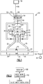
- Figure 1 shows an example fluid system 20.
- Fluid system 20 controls an actuator piston rod 22 which is connected to drive or position a component 24.
- Component 24 can be any number of mechanical components.
- the component 24 may position a variable vane assembly on a gas turbine engine.
- the connections and reasons for changing the angular orientation of the variable vane 25 may be as known. However, a control system, as will be described, is unique to this disclosure.
- the piston rod 22 drives with a piston 26, which is moved to translate by fluid driven into chambers 28 or 30.
- Supply/return lines 32/35 connect the chambers 28/30 to a spool valve 34.
- Spool valve 34 has springs 36 and 40 positioning lands 38 and 42. Fluid is driven into chambers 43 between the lands 42 and 38 to drive the spool valve and to selectively communicate return or supply lines to, in turn, drive the actuator 22.
- a drive motor 50 incorporates magnets 52 and 54 to change an angular attraction/opposition for an armature winding 55.
- Winding 55 is supplied with current and voltage from a supply 58.
- Supply 58 is controlled by a control 59.
- an end effector 56 is caused to pivot between flapper nozzles 61. As the end effector 56 pivots, it either restricts or opens respective nozzles 61.
- a feedback spring 60 connects the end effector to valve 34
- a voltage / current supply 58 was utilized with a suitably high frequency pulse width modulation mechanism to rapidly cycle the applied voltage on and off, resulting in the application of a steady current while minimizing heat and power dissipation in the controlling device.
- Applicant has recognized that the use of the pulse width modulation control at a lower frequency, to effectively provide "dithering," or a repeated perturbation of the position about some operating point, has efficiency losses as to energy, and also may result in undesirable wear.
- the control 59 monitors operation of the overall system 20 at step 100.
- the question is asked whether increased correction of the position is necessary. If so, then the frequency and/or the width of the pulses of a pulse width modulation control can be lowered, at the same time the applied voltage is increased or decreased.
- the frequency and/or the width of the pulses of a pulse width modulation control can be lowered, at the same time the applied voltage is increased or decreased.
- the magnetic perturbations of the armature magnetic field, and the mechanical perturbations of the driven system, such as here, at the pivoting end of effector 56 will become more pronounced. This, in turn, can result in more pronounced movement of the spool valve 34 and the actuator rod 22. This will provide better elimination of the hysteresis effect and more accurate overall positioning.
- there are undesirable losses due to use of the dithering especially as the frequency is lowered.
- a combination of higher voltage with smaller pulse width or lower pulse width modulation frequency or some combination of the two will increase the perturbations and dither
- the control will move the pulse width modulation to a higher frequency, reducing the magnetic and / or mechanical dither.
- Such a first step may be utilized when accurate positioning is not as necessary. Such as when gross movement is being achieved.
- the frequency is lowered somewhat from the first step, and/or the applied voltage is raised and pulse width is reduced.
- Such a step has a greater "ripple" or variation, and removes magnetic hysteresis effects such as from actuator 50. This is accomplished by having a perturbation in the magnetic field that exceeds the magnetic hysteresis band such that the commanded current results in a commanded magnetic field that oscillates around the hysteresis band in a manner known to reduce the effects of hysteresis in prior art .
- a third step may have still higher voltage/more narrow pulse width, and/or lower frequency from the second step.
- the ripple is larger and would tend to remove the effect of magnetic hysteresis and also mechanical hysteresis at the spool valve 34, due to the dithering effect of the implied current.
- an even lower frequency may be utilized.
- the dithering movement begins to be noticeable in the target system. Still, the target system will tend to oscillate about the desired position, and there is a reduction in frictional effect as described in the step above, due to the resulting lower dynamic friction rather than static friction.
- dither can be modulated instantaneously in real time, varying in duration and/or, amplitude, to suit the needs at that moment
- the dither when the system output is moving rapidly, and fine positioning accuracy is not required, during gross movements from one position to another, the dither could be small. If a system has arrived close to a desired position the dither can be increased to allow the system to position very accurately, then when the system has arrived very close to the desired position, the dither can be reduced again. Likewise when the system output is at a point where greater positioning accuracy is not needed, the dither can be small.
- a method of operating a fluid driven system includes the steps of operating a valve for selectively controlling a flow of fluid to a fluid actuator.
- the valve is provided with an electric voltage and current.
- a component is moved by the fluid actuator.
- a control applies pulse width modulation to the voltage or current.
- the control varies at least one of an applied voltage, pulse width or frequency of the pulse width modulation based upon conditions of the system.
- a control programmed to achieve the above variation may be incorporated into a full-authority digital electronic control for an associated engine, or may be a separate control.
Landscapes
- Engineering & Computer Science (AREA)
- General Engineering & Computer Science (AREA)
- Physics & Mathematics (AREA)
- Mechanical Engineering (AREA)
- Electromagnetism (AREA)
- Fluid Mechanics (AREA)
- Magnetically Actuated Valves (AREA)
- Power Engineering (AREA)
Claims (11)
- Fluidbetriebenes System, umfassend:einen Fluidaktuator (22, 26), um ein Fluid aufzunehmen, um eine Bewegung eines Bauteils (24) zu bewirken, wobei der Fluidaktuator (22, 26) eine Stellstange (22) aufweist, die mit dem Bauteil (24) verbunden werden kann;ein Ventil (34) zum selektiven Steuern des Fluidstroms zu dem Fluidaktuator, und einen Motor für das Ventil, der mit einer Spannung und einer elektrischen Stromstärke versorgt wird; undeine Steuerung (59) zum Anwenden einer Pulsweitenmodulationsänderung auf die bereitgestellte Spannung oder Stromstärke, und wobei die Steuerung so betrieben werden kann, dass sie die Pulsweitenmodulation der Spannung oder der Stromstärke basierend auf Bedingungen des Systems ändert, dadurch gekennzeichnet, dass die Steuerung so betrieben werden kann, dass sie ermittelt, ob eine verstärkte Korrektur einer Position der Stellstange für eine genauere Positionierung erforderlich ist, und falls nicht, die Pulsweitenmodulation auf eine höhere Frequenz bewegt, und, falls eine verstärkte Korrektur erforderlich ist, eine Frequenz der Pulsweitenmodulation durch die Steuerung herabgesetzt wird.
- Fluidbetriebenes System nach Anspruch 1, wobei der Fluidaktuator ein Hubkolben.
- Fluidbetriebenes System nach einem der vorstehenden Ansprüche, wobei ein Motor (50) für das eine Ankerspule (55) beinhaltet, die durch die Stromstärke versorgt wird, um, wiederum, einen Fluidstrom zum Fluidaktuator zu steuern.
- Fluidbetriebenes System nach einem der vorstehenden Ansprüche, wobei der Motor (50) die Fluidzufuhr zu dem Ventil steuert, wobei das Ventil die Fluidzufuhr zu dem Fluidaktuator steuert, wobei eine magnetische Hysterese an dem Motor vorliegt und eine mechanische Hysterese in Verbindung sowohl mit dem Ventil als auch mit dem Fluidaktuator vorliegt, und wobei die Pulsweitenmodulation eine Wirkung der magnetischen Hysterese und der mechanischen Hysterese einer Positionierung des Bauteils verringert.
- Fluidbetriebenes System nach Anspruch 4, wobei eine herabgesetzte Frequenz einer Pulsweitenmodulation einen größeren Teil der magnetischen und der mechanischen Hysterese eliminiert als eine höhere Frequenz.
- System nach einem der vorstehenden Ansprüche, wobei die Frequenz über mindestens drei Ebenen verändert wird.
- System nach einem der vorstehenden Ansprüche, wobei die Steuerung so betrieben werden kann, dass sie mindestens eines aus einer Dauer, einer Weite und einer Frequenz der Pulsweitenmodulation der Spannung oder der Stromstärke verändert.
- Verfahren zum Betreiben eines fluidbetriebenen Systems, Folgendes umfassend:Betreiben eines Motors für ein Ventil, um einen Fluidstrom zu einem Fluidaktuator zu steuern, und wobei der Motor mit einer Spannung und einer Stromstärke versorgt wird; undund Bewegen eines Bauteils mit einer Stellstange des Fluidaktuators durch Anwenden einer Pulsweitenmodulation auf die Spannung oder Stromstärke, und wobei die Steuerung die Pulsweitenmodulation der Stromstärke basierend auf Bedingungen des Systems ändert, dadurch gekennzeichnet, dass die Steuerung so betrieben werden kann, dass sie ermittelt, ob eine verstärkte Korrektur einer Position der Stellstange für eine genauere Positionierung erforderlich ist, und falls nicht, die Pulsweitenmodulation auf eine höhere Frequenz bewegt, und, falls eine verstärkte Korrektur erforderlich ist, eine Frequenz der Pulsweitenmodulation durch die Steuerung herabgesetzt wird.
- Verfahren nach Anspruch 8, wobei eine herabgesetzte Frequenz einen größeren Teil der magnetischen und der mechanischen Hysterese eliminiert als eine höhere Frequenz.
- Verfahren nach Anspruch 8 oder 9, wobei das Bauteil eine verstellbare Leitschaufel in einem Gasturbinentriebwerk ist und vorzugsweise wobei der Fluidaktuator ein Hubkolben ist.
- Verfahren nach Anspruch 8, 9 oder 10, wobei die Steuerung mindestens eines aus einer Dauer, einer Weite und einer Frequenz der Pulsweitenmodulation der Spannung oder der Stromstärke verändert.
Applications Claiming Priority (1)
| Application Number | Priority Date | Filing Date | Title |
|---|---|---|---|
| US16/028,681 US20200011447A1 (en) | 2018-07-06 | 2018-07-06 | Variable dither control system for a fluid actuator |
Publications (2)
| Publication Number | Publication Date |
|---|---|
| EP3591240A1 EP3591240A1 (de) | 2020-01-08 |
| EP3591240B1 true EP3591240B1 (de) | 2022-01-05 |
Family
ID=67437545
Family Applications (1)
| Application Number | Title | Priority Date | Filing Date |
|---|---|---|---|
| EP19184671.6A Active EP3591240B1 (de) | 2018-07-06 | 2019-07-05 | Variables dithersteuerungssystem für einen fluidaktuator |
Country Status (2)
| Country | Link |
|---|---|
| US (1) | US20200011447A1 (de) |
| EP (1) | EP3591240B1 (de) |
Family Cites Families (9)
| Publication number | Priority date | Publication date | Assignee | Title |
|---|---|---|---|---|
| US4510848A (en) * | 1982-09-30 | 1985-04-16 | General Electric Company | Shear-type fail-fixed servovalve |
| US4538644A (en) * | 1983-06-09 | 1985-09-03 | Applied Power Inc. | Pressure regulator |
| US6938592B2 (en) * | 2002-06-17 | 2005-09-06 | Borgwarner Inc. | Control method for electro-hydraulic control valves over temperature range |
| DE10304711B4 (de) * | 2003-02-06 | 2007-10-18 | Daimlerchrysler Ag | Verfahren zur Steuerung eines Elektromagnetventils, insbesondere für ein Automatikgetriebe eines Kraftfahrzeugs |
| US6895751B1 (en) * | 2004-03-08 | 2005-05-24 | Christopher Greentree | Vane control |
| US8066474B1 (en) * | 2006-06-16 | 2011-11-29 | Jansen's Aircraft Systems Controls, Inc. | Variable guide vane actuator |
| US8786138B2 (en) * | 2010-05-21 | 2014-07-22 | General Electric Company | Systems, methods, and apparatus for controlling actuator drive current using bi-directional hysteresis control |
| WO2015007318A1 (en) * | 2013-07-18 | 2015-01-22 | Abb Technology Ltd | Discrete pilot stage valve arrangement with fail freeze mode |
| US10624263B2 (en) * | 2016-06-21 | 2020-04-21 | Macdon Industries Ltd | Crop machine with an electronically controlled hydraulic cylinder flotation system |
-
2018
- 2018-07-06 US US16/028,681 patent/US20200011447A1/en active Pending
-
2019
- 2019-07-05 EP EP19184671.6A patent/EP3591240B1/de active Active
Non-Patent Citations (1)
| Title |
|---|
| None * |
Also Published As
| Publication number | Publication date |
|---|---|
| EP3591240A1 (de) | 2020-01-08 |
| US20200011447A1 (en) | 2020-01-09 |
Similar Documents
| Publication | Publication Date | Title |
|---|---|---|
| JP4445389B2 (ja) | 可変形態ターボチャージャの改良された過渡応答のための制御システム | |
| EP1664604B1 (de) | System, verfahren und vorrichtung zur verringerung von reibungskräften und zum ausgleich von gedächtnislegierungsbetätigten ventilen und -ventilsystemen bei hohen temperaturen | |
| US7853360B2 (en) | Method and device for determining a PWM signal on which a dither frequency is superimposed in order to control a solenoid valve | |
| EP3030816B1 (de) | Steuerung eines elektrisch betriebenen aktuators | |
| Gentile et al. | Experimental tests on position control of a pneumatic actuator using on/off solenoid valves | |
| KR20140067125A (ko) | 파일럿-작동 전자유압밸브용 위치 제어기 | |
| EP0810350A1 (de) | Verfahren zur Ermittlung eines Fehlers bei einem elektromagnetisch betätigten Einlass- oder Auslassventil | |
| EP3591240B1 (de) | Variables dithersteuerungssystem für einen fluidaktuator | |
| US20010022163A1 (en) | Process for operating an electromagnetic actuator | |
| US7260462B2 (en) | Method for controlling an electromagnetic valve, in particular for an automatic transmission of a motor vehicle | |
| JP2024506134A (ja) | 空気圧シリンダシステム | |
| EP3942208B1 (de) | Verfahren zum betrieb eines steuerventils, heizungs-, lüftungs- und klimaanlagen stellantrieb und computer programm produkt | |
| RU2368932C1 (ru) | Электрогидравлический следящий привод непосредственного управления с адаптивными свойствами | |
| CN1856640A (zh) | 用于喷射器驱动模块的功率供应和控制方法 | |
| JP2010061481A (ja) | 流量制御弁の制御装置 | |
| Reinertz | A comparative study on dither signals and their parameterisation | |
| JP7594959B2 (ja) | 電磁弁の制御装置 | |
| EP3806127B1 (de) | Steuersystem und verfahren für einen elektromechanischen schütz einer leistungsschaltung | |
| CN105593536B (zh) | 具有故障冻结模式的分立式先导级阀装置 | |
| JPH04233010A (ja) | パルス幅変調圧力制御弁構成 | |
| US11118488B2 (en) | Actuating device for a camshaft timing apparatus | |
| US7054128B2 (en) | Control apparatus for electromagnetically driven valve and control method of the same | |
| JPH0579869B2 (de) | ||
| US11837401B2 (en) | Actuation system to achieve soft landing and the control method thereof | |
| Norhisam et al. | Positioning system for sensor less linear DC motor |
Legal Events
| Date | Code | Title | Description |
|---|---|---|---|
| PUAI | Public reference made under article 153(3) epc to a published international application that has entered the european phase |
Free format text: ORIGINAL CODE: 0009012 |
|
| STAA | Information on the status of an ep patent application or granted ep patent |
Free format text: STATUS: THE APPLICATION HAS BEEN PUBLISHED |
|
| AK | Designated contracting states |
Kind code of ref document: A1 Designated state(s): AL AT BE BG CH CY CZ DE DK EE ES FI FR GB GR HR HU IE IS IT LI LT LU LV MC MK MT NL NO PL PT RO RS SE SI SK SM TR |
|
| AX | Request for extension of the european patent |
Extension state: BA ME |
|
| STAA | Information on the status of an ep patent application or granted ep patent |
Free format text: STATUS: REQUEST FOR EXAMINATION WAS MADE |
|
| 17P | Request for examination filed |
Effective date: 20200708 |
|
| RBV | Designated contracting states (corrected) |
Designated state(s): AL AT BE BG CH CY CZ DE DK EE ES FI FR GB GR HR HU IE IS IT LI LT LU LV MC MK MT NL NO PL PT RO RS SE SI SK SM TR |
|
| STAA | Information on the status of an ep patent application or granted ep patent |
Free format text: STATUS: EXAMINATION IS IN PROGRESS |
|
| 17Q | First examination report despatched |
Effective date: 20201125 |
|
| GRAP | Despatch of communication of intention to grant a patent |
Free format text: ORIGINAL CODE: EPIDOSNIGR1 |
|
| STAA | Information on the status of an ep patent application or granted ep patent |
Free format text: STATUS: GRANT OF PATENT IS INTENDED |
|
| RIC1 | Information provided on ipc code assigned before grant |
Ipc: F15B 13/043 20060101AFI20210723BHEP Ipc: F15B 13/044 20060101ALN20210723BHEP |
|
| INTG | Intention to grant announced |
Effective date: 20210816 |
|
| GRAS | Grant fee paid |
Free format text: ORIGINAL CODE: EPIDOSNIGR3 |
|
| GRAA | (expected) grant |
Free format text: ORIGINAL CODE: 0009210 |
|
| STAA | Information on the status of an ep patent application or granted ep patent |
Free format text: STATUS: THE PATENT HAS BEEN GRANTED |
|
| AK | Designated contracting states |
Kind code of ref document: B1 Designated state(s): AL AT BE BG CH CY CZ DE DK EE ES FI FR GB GR HR HU IE IS IT LI LT LU LV MC MK MT NL NO PL PT RO RS SE SI SK SM TR |
|
| REG | Reference to a national code |
Ref country code: GB Ref legal event code: FG4D |
|
| REG | Reference to a national code |
Ref country code: CH Ref legal event code: EP |
|
| REG | Reference to a national code |
Ref country code: AT Ref legal event code: REF Ref document number: 1460841 Country of ref document: AT Kind code of ref document: T Effective date: 20220115 |
|
| REG | Reference to a national code |
Ref country code: DE Ref legal event code: R096 Ref document number: 602019010592 Country of ref document: DE |
|
| REG | Reference to a national code |
Ref country code: IE Ref legal event code: FG4D |
|
| REG | Reference to a national code |
Ref country code: LT Ref legal event code: MG9D |
|
| REG | Reference to a national code |
Ref country code: NL Ref legal event code: MP Effective date: 20220105 |
|
| REG | Reference to a national code |
Ref country code: AT Ref legal event code: MK05 Ref document number: 1460841 Country of ref document: AT Kind code of ref document: T Effective date: 20220105 |
|
| PG25 | Lapsed in a contracting state [announced via postgrant information from national office to epo] |
Ref country code: NL Free format text: LAPSE BECAUSE OF FAILURE TO SUBMIT A TRANSLATION OF THE DESCRIPTION OR TO PAY THE FEE WITHIN THE PRESCRIBED TIME-LIMIT Effective date: 20220105 |
|
| PG25 | Lapsed in a contracting state [announced via postgrant information from national office to epo] |
Ref country code: SE Free format text: LAPSE BECAUSE OF FAILURE TO SUBMIT A TRANSLATION OF THE DESCRIPTION OR TO PAY THE FEE WITHIN THE PRESCRIBED TIME-LIMIT Effective date: 20220105 Ref country code: RS Free format text: LAPSE BECAUSE OF FAILURE TO SUBMIT A TRANSLATION OF THE DESCRIPTION OR TO PAY THE FEE WITHIN THE PRESCRIBED TIME-LIMIT Effective date: 20220105 Ref country code: PT Free format text: LAPSE BECAUSE OF FAILURE TO SUBMIT A TRANSLATION OF THE DESCRIPTION OR TO PAY THE FEE WITHIN THE PRESCRIBED TIME-LIMIT Effective date: 20220505 Ref country code: NO Free format text: LAPSE BECAUSE OF FAILURE TO SUBMIT A TRANSLATION OF THE DESCRIPTION OR TO PAY THE FEE WITHIN THE PRESCRIBED TIME-LIMIT Effective date: 20220405 Ref country code: LT Free format text: LAPSE BECAUSE OF FAILURE TO SUBMIT A TRANSLATION OF THE DESCRIPTION OR TO PAY THE FEE WITHIN THE PRESCRIBED TIME-LIMIT Effective date: 20220105 Ref country code: HR Free format text: LAPSE BECAUSE OF FAILURE TO SUBMIT A TRANSLATION OF THE DESCRIPTION OR TO PAY THE FEE WITHIN THE PRESCRIBED TIME-LIMIT Effective date: 20220105 Ref country code: ES Free format text: LAPSE BECAUSE OF FAILURE TO SUBMIT A TRANSLATION OF THE DESCRIPTION OR TO PAY THE FEE WITHIN THE PRESCRIBED TIME-LIMIT Effective date: 20220105 Ref country code: BG Free format text: LAPSE BECAUSE OF FAILURE TO SUBMIT A TRANSLATION OF THE DESCRIPTION OR TO PAY THE FEE WITHIN THE PRESCRIBED TIME-LIMIT Effective date: 20220405 |
|
| PG25 | Lapsed in a contracting state [announced via postgrant information from national office to epo] |
Ref country code: PL Free format text: LAPSE BECAUSE OF FAILURE TO SUBMIT A TRANSLATION OF THE DESCRIPTION OR TO PAY THE FEE WITHIN THE PRESCRIBED TIME-LIMIT Effective date: 20220105 Ref country code: LV Free format text: LAPSE BECAUSE OF FAILURE TO SUBMIT A TRANSLATION OF THE DESCRIPTION OR TO PAY THE FEE WITHIN THE PRESCRIBED TIME-LIMIT Effective date: 20220105 Ref country code: GR Free format text: LAPSE BECAUSE OF FAILURE TO SUBMIT A TRANSLATION OF THE DESCRIPTION OR TO PAY THE FEE WITHIN THE PRESCRIBED TIME-LIMIT Effective date: 20220406 Ref country code: FI Free format text: LAPSE BECAUSE OF FAILURE TO SUBMIT A TRANSLATION OF THE DESCRIPTION OR TO PAY THE FEE WITHIN THE PRESCRIBED TIME-LIMIT Effective date: 20220105 Ref country code: AT Free format text: LAPSE BECAUSE OF FAILURE TO SUBMIT A TRANSLATION OF THE DESCRIPTION OR TO PAY THE FEE WITHIN THE PRESCRIBED TIME-LIMIT Effective date: 20220105 |
|
| PG25 | Lapsed in a contracting state [announced via postgrant information from national office to epo] |
Ref country code: IS Free format text: LAPSE BECAUSE OF FAILURE TO SUBMIT A TRANSLATION OF THE DESCRIPTION OR TO PAY THE FEE WITHIN THE PRESCRIBED TIME-LIMIT Effective date: 20220505 |
|
| REG | Reference to a national code |
Ref country code: DE Ref legal event code: R097 Ref document number: 602019010592 Country of ref document: DE |
|
| PG25 | Lapsed in a contracting state [announced via postgrant information from national office to epo] |
Ref country code: SM Free format text: LAPSE BECAUSE OF FAILURE TO SUBMIT A TRANSLATION OF THE DESCRIPTION OR TO PAY THE FEE WITHIN THE PRESCRIBED TIME-LIMIT Effective date: 20220105 Ref country code: SK Free format text: LAPSE BECAUSE OF FAILURE TO SUBMIT A TRANSLATION OF THE DESCRIPTION OR TO PAY THE FEE WITHIN THE PRESCRIBED TIME-LIMIT Effective date: 20220105 Ref country code: RO Free format text: LAPSE BECAUSE OF FAILURE TO SUBMIT A TRANSLATION OF THE DESCRIPTION OR TO PAY THE FEE WITHIN THE PRESCRIBED TIME-LIMIT Effective date: 20220105 Ref country code: EE Free format text: LAPSE BECAUSE OF FAILURE TO SUBMIT A TRANSLATION OF THE DESCRIPTION OR TO PAY THE FEE WITHIN THE PRESCRIBED TIME-LIMIT Effective date: 20220105 Ref country code: DK Free format text: LAPSE BECAUSE OF FAILURE TO SUBMIT A TRANSLATION OF THE DESCRIPTION OR TO PAY THE FEE WITHIN THE PRESCRIBED TIME-LIMIT Effective date: 20220105 Ref country code: CZ Free format text: LAPSE BECAUSE OF FAILURE TO SUBMIT A TRANSLATION OF THE DESCRIPTION OR TO PAY THE FEE WITHIN THE PRESCRIBED TIME-LIMIT Effective date: 20220105 |
|
| PLBE | No opposition filed within time limit |
Free format text: ORIGINAL CODE: 0009261 |
|
| STAA | Information on the status of an ep patent application or granted ep patent |
Free format text: STATUS: NO OPPOSITION FILED WITHIN TIME LIMIT |
|
| PG25 | Lapsed in a contracting state [announced via postgrant information from national office to epo] |
Ref country code: AL Free format text: LAPSE BECAUSE OF FAILURE TO SUBMIT A TRANSLATION OF THE DESCRIPTION OR TO PAY THE FEE WITHIN THE PRESCRIBED TIME-LIMIT Effective date: 20220105 |
|
| 26N | No opposition filed |
Effective date: 20221006 |
|
| PG25 | Lapsed in a contracting state [announced via postgrant information from national office to epo] |
Ref country code: SI Free format text: LAPSE BECAUSE OF FAILURE TO SUBMIT A TRANSLATION OF THE DESCRIPTION OR TO PAY THE FEE WITHIN THE PRESCRIBED TIME-LIMIT Effective date: 20220105 Ref country code: MC Free format text: LAPSE BECAUSE OF FAILURE TO SUBMIT A TRANSLATION OF THE DESCRIPTION OR TO PAY THE FEE WITHIN THE PRESCRIBED TIME-LIMIT Effective date: 20220105 |
|
| REG | Reference to a national code |
Ref country code: CH Ref legal event code: PL |
|
| REG | Reference to a national code |
Ref country code: BE Ref legal event code: MM Effective date: 20220731 |
|
| PG25 | Lapsed in a contracting state [announced via postgrant information from national office to epo] |
Ref country code: LU Free format text: LAPSE BECAUSE OF NON-PAYMENT OF DUE FEES Effective date: 20220705 Ref country code: LI Free format text: LAPSE BECAUSE OF NON-PAYMENT OF DUE FEES Effective date: 20220731 Ref country code: CH Free format text: LAPSE BECAUSE OF NON-PAYMENT OF DUE FEES Effective date: 20220731 |
|
| PG25 | Lapsed in a contracting state [announced via postgrant information from national office to epo] |
Ref country code: BE Free format text: LAPSE BECAUSE OF NON-PAYMENT OF DUE FEES Effective date: 20220731 |
|
| P01 | Opt-out of the competence of the unified patent court (upc) registered |
Effective date: 20230522 |
|
| PG25 | Lapsed in a contracting state [announced via postgrant information from national office to epo] |
Ref country code: IT Free format text: LAPSE BECAUSE OF FAILURE TO SUBMIT A TRANSLATION OF THE DESCRIPTION OR TO PAY THE FEE WITHIN THE PRESCRIBED TIME-LIMIT Effective date: 20220105 Ref country code: IE Free format text: LAPSE BECAUSE OF NON-PAYMENT OF DUE FEES Effective date: 20220705 |
|
| PG25 | Lapsed in a contracting state [announced via postgrant information from national office to epo] |
Ref country code: HU Free format text: LAPSE BECAUSE OF FAILURE TO SUBMIT A TRANSLATION OF THE DESCRIPTION OR TO PAY THE FEE WITHIN THE PRESCRIBED TIME-LIMIT; INVALID AB INITIO Effective date: 20190705 |
|
| PG25 | Lapsed in a contracting state [announced via postgrant information from national office to epo] |
Ref country code: MK Free format text: LAPSE BECAUSE OF FAILURE TO SUBMIT A TRANSLATION OF THE DESCRIPTION OR TO PAY THE FEE WITHIN THE PRESCRIBED TIME-LIMIT Effective date: 20220105 Ref country code: CY Free format text: LAPSE BECAUSE OF FAILURE TO SUBMIT A TRANSLATION OF THE DESCRIPTION OR TO PAY THE FEE WITHIN THE PRESCRIBED TIME-LIMIT Effective date: 20220105 |
|
| PG25 | Lapsed in a contracting state [announced via postgrant information from national office to epo] |
Ref country code: MT Free format text: LAPSE BECAUSE OF FAILURE TO SUBMIT A TRANSLATION OF THE DESCRIPTION OR TO PAY THE FEE WITHIN THE PRESCRIBED TIME-LIMIT Effective date: 20220105 |
|
| PGFP | Annual fee paid to national office [announced via postgrant information from national office to epo] |
Ref country code: GB Payment date: 20250619 Year of fee payment: 7 |
|
| PGFP | Annual fee paid to national office [announced via postgrant information from national office to epo] |
Ref country code: FR Payment date: 20250620 Year of fee payment: 7 |
|
| PGFP | Annual fee paid to national office [announced via postgrant information from national office to epo] |
Ref country code: DE Payment date: 20250620 Year of fee payment: 7 |
|
| PG25 | Lapsed in a contracting state [announced via postgrant information from national office to epo] |
Ref country code: TR Free format text: LAPSE BECAUSE OF FAILURE TO SUBMIT A TRANSLATION OF THE DESCRIPTION OR TO PAY THE FEE WITHIN THE PRESCRIBED TIME-LIMIT Effective date: 20220105 |