EP3591150A2 - Opening control with mechanical reassembly - Google Patents
Opening control with mechanical reassembly Download PDFInfo
- Publication number
- EP3591150A2 EP3591150A2 EP19160955.1A EP19160955A EP3591150A2 EP 3591150 A2 EP3591150 A2 EP 3591150A2 EP 19160955 A EP19160955 A EP 19160955A EP 3591150 A2 EP3591150 A2 EP 3591150A2
- Authority
- EP
- European Patent Office
- Prior art keywords
- handle
- control
- lever
- drive
- kinematic chain
- Prior art date
- Legal status (The legal status is an assumption and is not a legal conclusion. Google has not performed a legal analysis and makes no representation as to the accuracy of the status listed.)
- Withdrawn
Links
Images


Classifications
-
- B—PERFORMING OPERATIONS; TRANSPORTING
- B60—VEHICLES IN GENERAL
- B60J—WINDOWS, WINDSCREENS, NON-FIXED ROOFS, DOORS, OR SIMILAR DEVICES FOR VEHICLES; REMOVABLE EXTERNAL PROTECTIVE COVERINGS SPECIALLY ADAPTED FOR VEHICLES
- B60J5/00—Doors
- B60J5/04—Doors arranged at the vehicle sides
- B60J5/0412—Lower door structure
- B60J5/0416—Assembly panels to be installed in doors as a module with components, e.g. lock or window lifter, attached thereto
-
- E—FIXED CONSTRUCTIONS
- E05—LOCKS; KEYS; WINDOW OR DOOR FITTINGS; SAFES
- E05B—LOCKS; ACCESSORIES THEREFOR; HANDCUFFS
- E05B81/00—Power-actuated vehicle locks
-
- E—FIXED CONSTRUCTIONS
- E05—LOCKS; KEYS; WINDOW OR DOOR FITTINGS; SAFES
- E05B—LOCKS; ACCESSORIES THEREFOR; HANDCUFFS
- E05B85/00—Details of vehicle locks not provided for in groups E05B77/00 - E05B83/00
- E05B85/10—Handles
- E05B85/107—Pop-out handles, e.g. sliding outwardly before rotation
-
- E—FIXED CONSTRUCTIONS
- E05—LOCKS; KEYS; WINDOW OR DOOR FITTINGS; SAFES
- E05B—LOCKS; ACCESSORIES THEREFOR; HANDCUFFS
- E05B85/00—Details of vehicle locks not provided for in groups E05B77/00 - E05B83/00
- E05B85/10—Handles
- E05B85/14—Handles pivoted about an axis parallel to the wing
- E05B85/16—Handles pivoted about an axis parallel to the wing a longitudinal grip part being pivoted at one end about an axis perpendicular to the longitudinal axis of the grip part
-
- E—FIXED CONSTRUCTIONS
- E05—LOCKS; KEYS; WINDOW OR DOOR FITTINGS; SAFES
- E05B—LOCKS; ACCESSORIES THEREFOR; HANDCUFFS
- E05B81/00—Power-actuated vehicle locks
- E05B81/02—Power-actuated vehicle locks characterised by the type of actuators used
- E05B81/04—Electrical
- E05B81/08—Electrical using electromagnets or solenoids
-
- E—FIXED CONSTRUCTIONS
- E05—LOCKS; KEYS; WINDOW OR DOOR FITTINGS; SAFES
- E05B—LOCKS; ACCESSORIES THEREFOR; HANDCUFFS
- E05B81/00—Power-actuated vehicle locks
- E05B81/54—Electrical circuits
- E05B81/90—Manual override in case of power failure
-
- E—FIXED CONSTRUCTIONS
- E05—LOCKS; KEYS; WINDOW OR DOOR FITTINGS; SAFES
- E05B—LOCKS; ACCESSORIES THEREFOR; HANDCUFFS
- E05B85/00—Details of vehicle locks not provided for in groups E05B77/00 - E05B83/00
- E05B85/10—Handles
- E05B85/103—Handles creating a completely closed wing surface
Definitions
- the present invention relates to an opening control for a motor vehicle opening.
- the invention relates more particularly, but not exclusively, to an external opening control which comprises means for emergency mechanical unlocking in the event of failure of the electrical actuation means of the lock.
- This opening command applies equally well to unlocking with a conventional lock or with an electrically actuated lock, also known as the "electronic lock” or according to the English terminology “electronic latch” or “e -latch ".
- an external opening control comprises a fixed support intended to be mounted on the opening and a handle mounted movably on the support, for example pivotally mounted on the support while being articulated in rotation about an axis.
- the opening control also includes an unlocking mechanism, which when the handle is operated in traction, allows the unlocking of the lock and thus the opening of the door.
- the lock conventionally comprises a bolt secured to the door capable of cooperating with a keeper secured to the body. When the door is opened from outside the vehicle, the latch is released from the strike by actuation of the exterior opening control.
- the invention relates more particularly to a handle opening control of the “flush” type, that is to say that the support on which the handle is movably mounted forms a cavity capable of receiving the handle in the retracted configuration.
- the exterior surface of the handle In this retracted configuration, the exterior surface of the handle is flush with the exterior surface of the exterior wall of the opening.
- the handle In the extended or deployed configuration, the handle at least partially exits the support cavity so that it can be grasped by a user of the vehicle in order to open the door. To do this, the user can move the handle further outwards in order to control the door lock.
- the opening control comprises an electric ejection mechanism of the handle to allow the grip of the handle by the user and the opening of the opening.
- the electrical ejection mechanism operates from a power supply supplied by example by a battery of the motor vehicle and can be controlled electronically remotely using a key, a mobile phone or any other device allowing remote communication.
- the object of the invention is to remedy these drawbacks and to provide a compact, robust opening control which makes it possible, in a simple manner, to perform mechanical emergency unlocking.
- An opening command may include one or more of the following characteristics.
- the mechanism comprises a drive member, a kinematic chain for mechanical winding of the drive member and a kinematic chain for mechanically driving the handle by the drive member.
- the motor member is configured to accumulate mechanical energy during the action of driving in the handle and to restore mechanical energy in driving movement of the handle as soon as the action of driving is completed.
- the drive member comprises a shaft, a drum and a drive spring housed in the drum wound in a spiral around the drum shaft.
- the motor member comprises a winding wheel provided with a toothing at the periphery mounted integral with the drum shaft.
- the mainspring has an inner end to the winding attached to the drum shaft and an outer end attached to the drum.
- the drive kinematic chain comprises a drive shaft in movement of the handle provided with an eccentric to transform a rotary movement of the shaft into an alternative movement of pivoting of the handle.
- the drive shaft and the drum shaft comprise unidirectional rotational connection means.
- the cam is carried by the drum shaft and the locking element is mounted inside a cylindrical cage shaped as a hub body receiving the drum shaft.
- the winding kinematic chain comprises at least one means of transmitting the driving-in movement from the handle to the motor member.
- the transmission means is a lever pivotally mounted relative to the housing and has a circular sector shape pivotally connected at one end to a stop member for depressing the handle and forming at the other end an arc of a toothed gear circle.
- the transmission ratio of the transmission means to the winding wheel of the motor member is defined such that the depression of the handle causes an angular rotation of 2 ⁇ of the winding wheel.
- the mechanism comprises means for stopping the drive kinematic chain during the driving action.
- the stop means comprises a resilient return transmission pawl pivotally mounted on the winding drive train and a locking lever of the drive drive train pivoted between a stop position and a starting position of the drive chain, the lever having a beak or nose or finger capable of engaging with the transmission pawl at the end of the depressing action to allow the lever to tilt from the stopped position at the starting position of the drive kinematic chain.
- the winding drive train comprises a unidirectional transmission train in the handle direction to the drive member, in particular of the freewheel type.
- the freewheel comprises a one-way clutch comprising a pair of toothed pinions coupled to each other in rotation at least in one direction by means of respective coupling elements.
- the drive kinematic chain comprises a damping member configured to slow the stroke of the handle at least from the ejected position to the flush position.
- the control preferably further comprises a pivot lever for the ejecting and / or retracting handle and means for electrically actuating the pivot lever.
- the lever has a stirrup shape inside which the handle can be engaged and comprises at least one upper transverse bar for bearing on an upper bearing wall of the handle and a lower transverse support bar on a lower support wall of the handle and the lever comprises an elastic return member of the lever.
- a lever for locking the drive kinematic chain is pivotally mounted between a stop position and a chain start position, the lever being able to switch to the start position during exceeding a predefined torque-spring threshold for reassembling the drive member.
- the support 12 has a generally parallelepiped shape and is adapted to be housed in a cutout or a recess in the outer panel of the opening so that its outer face is flush with the surface of the outer panel of the opening. .
- the support 12 is also open on the side of its external face and closed by a bottom on the internal side in order to delimit the cavity 14 intended to accommodate the handle 16.
- the opening control 10 comprises a return lever 20.
- This return lever 20 comprises in the example described a rotary cage 22 and a return shaft 24 as well as a return spring 26 return intended to be housed at the interior of the rotary cage 22.
- the rotary cage 22 comprises for example a means for retaining one end of a Bowden cable (not shown).
- the assembly 20 is intended to be mounted on the support 12 as illustrated in the figure 1 .
- the output gear 144 defines a housing for partially receiving the input gear 142 so that the input gear 142 has a peripheral outer side wall which slides against the peripheral inner side wall of the housing.
- the output gear 144 has two internal partitions 150 in the form of a circular sector.
- the two cylinders 146 are placed in the space remaining between the drum and the circular sectors. The cylinders are compressed against the circular sectors by two springs.
- the blocking element 182 is movably mounted inside the cage 186 between an active projecting interaction position inside the cage 186 and an inactive position retracted tangentially to an internal wall 188 of the cage 186 and the cam 184 of the drum shaft 114 is provided with a cam profile which can interact with the locking element 182.
- the locking element 182 comprises for example a pivoting pawl resiliently returned to the position of interaction protruding by a spring 189.
- the cam profile comprises a retraction ramp provided with an end stop 188 against which the rotary pawl 182 engages.
- the pawl 210 is pivotally mounted on the transmission lever 130 with an elastic return spring 212.
- the hook 224 is released from the notch 226 when the user stops the insertion on the handle 16 and when the transmission lever 130 begins to rotate in a direction opposite to the direction of insertion of the handle 16, under the impulse of the stop spring 137.
- the actuator 60 controls the output of the jack 62 causing the ejection arm 70 to pivot.
- the latter will push against the lower branch 36 of the ejection bracket 30 to 1 against the return force exerted by the return spring 38 to accompany the ejection of the handle 16.
- the eccentric 172 of the drive shaft 170 makes a full turn. In the first half-turn, the eccentric 172 will push the handle 16 towards the high. In the second half-turn, the eccentric 172 will return the handle 16 to its initial position.
- the eccentric shaft 172 would be released when reaching a predefined spring torque so that the stop member 200 would be formed only by the lever 220.
- the lever 220 should for example have at the end a V-shaped hook to allow its release when reaching a predefined torque of the mainspring.
Abstract
La commande (10) comprend un boîtier (12), une poignée (16) montée mobile entre au moins une position affleurante dans laquelle la poignée (16) et une position éjectée dans laquelle la poignée (16) est au moins partiellement sortie du boîtier (12). Selon l'invention, la commande (10) comprend un mécanisme (100) configuré pour être déclenché mécaniquement en réponse à une action d'enfoncement dans le boîtier (12) de la poignée (16), la fin de l'action d'enfoncement étant apte à provoquer le déclenchement du mécanisme (100). En outre, le mécanisme (100) est configuré pour entraîner automatiquement en mouvement la poignée (16) selon tout ou partie d'une course partant d'une position enfoncée de la poignée (16) à la position affleurante en passant par la position éjectée.The control (10) comprises a housing (12), a handle (16) movably mounted between at least one flush position in which the handle (16) and an ejected position in which the handle (16) is at least partially removed from the housing (12). According to the invention, the control (10) comprises a mechanism (100) configured to be triggered mechanically in response to a pressing action in the housing (12) of the handle (16), the end of the action of depression being able to cause the triggering of the mechanism (100). In addition, the mechanism (100) is configured to automatically drive in movement the handle (16) according to all or part of a stroke starting from a depressed position of the handle (16) in the flush position passing through the ejected position. .
Description
La présente invention concerne une commande d'ouverture pour ouvrant de véhicule automobile. L'invention concerne plus particulièrement mais non exclusivement une commande d'ouverture extérieure qui comprend des moyens de déverrouillage mécanique de secours en cas de défaillance des moyens d'actionnement électrique de la serrure. Cette commande d'ouverture s'applique aussi bien à un déverrouillage avec une serrure conventionnelle ou avec une serrure à actionnement électrique, connue également sous l'expression « serrure électronique » ou encore selon la terminologie anglo-saxonne « electronic latch » ou « e-latch ».The present invention relates to an opening control for a motor vehicle opening. The invention relates more particularly, but not exclusively, to an external opening control which comprises means for emergency mechanical unlocking in the event of failure of the electrical actuation means of the lock. This opening command applies equally well to unlocking with a conventional lock or with an electrically actuated lock, also known as the "electronic lock" or according to the English terminology "electronic latch" or "e -latch ".
De façon générale, une commande d'ouverture extérieure comprend un support fixe destiné à être monté sur l'ouvrant et une poignée montée mobile sur le support, par exemple montée pivotante sur le support en étant articulée en rotation autour d'un axe.In general, an external opening control comprises a fixed support intended to be mounted on the opening and a handle mounted movably on the support, for example pivotally mounted on the support while being articulated in rotation about an axis.
La commande d'ouverture comprend également un mécanisme de déverrouillage, qui lorsque la poignée est manœuvrée en traction, permet le déverrouillage de la serrure et ainsi l'ouverture de la porte. La serrure comprend de façon classique un pêne solidaire de la porte apte à coopérer avec une gâche solidaire de la carrosserie. Lors de l'ouverture de la porte depuis l'extérieur du véhicule, le pêne est dégagé de la gâche par actionnement de la commande d'ouverture extérieure.The opening control also includes an unlocking mechanism, which when the handle is operated in traction, allows the unlocking of the lock and thus the opening of the door. The lock conventionally comprises a bolt secured to the door capable of cooperating with a keeper secured to the body. When the door is opened from outside the vehicle, the latch is released from the strike by actuation of the exterior opening control.
L'invention concerne plus particulièrement une commande d'ouverture à poignée du type « flush », c'est-à-dire que le support sur lequel la poignée est montée mobile forme une cavité apte à recevoir la poignée en configuration rentrée. Dans cette configuration rentrée, la surface extérieure de la poignée affleure la surface extérieure de la paroi extérieure de l'ouvrant. En configuration sortie ou déployée, la poignée sort au moins partiellement de la cavité du support de manière à pouvoir être saisie par un utilisateur du véhicule en vue d'ouvrir la porte. Pour ce faire, l'utilisateur peut déplacer la poignée davantage vers l'extérieur afin de commander la serrure de la porte.The invention relates more particularly to a handle opening control of the “flush” type, that is to say that the support on which the handle is movably mounted forms a cavity capable of receiving the handle in the retracted configuration. In this retracted configuration, the exterior surface of the handle is flush with the exterior surface of the exterior wall of the opening. In the extended or deployed configuration, the handle at least partially exits the support cavity so that it can be grasped by a user of the vehicle in order to open the door. To do this, the user can move the handle further outwards in order to control the door lock.
En général, la commande d'ouverture comprend un mécanisme d'éjection électrique de la poignée pour permettre la prise en main de la poignée par l'utilisateur et l'ouverture de l'ouvrant. Le mécanisme d'éjection électrique fonctionne à partir d'une alimentation électrique délivrée par exemple par une batterie du véhicule automobile et peut être commandé électroniquement à distance grâce à une clé, un téléphone portable ou tout autre dispositif autorisant une communication à distance.In general, the opening control comprises an electric ejection mechanism of the handle to allow the grip of the handle by the user and the opening of the opening. The electrical ejection mechanism operates from a power supply supplied by example by a battery of the motor vehicle and can be controlled electronically remotely using a key, a mobile phone or any other device allowing remote communication.
Toutefois, en cas de défaillance de cette alimentation électrique, la poignée à éjection électrique n'est pas utilisable et l'utilisateur ne peut pas entrer dans le véhicule. Il est donc nécessaire de disposer d'un mécanisme de secours permettant de déverrouiller la porte du véhicule notamment lorsque la batterie n'a pas suffisamment d'énergie pour que le mécanisme de d'éjection électrique fonctionne.However, in the event of failure of this electrical supply, the electric ejection handle cannot be used and the user cannot enter the vehicle. It is therefore necessary to have a backup mechanism for unlocking the vehicle door, especially when the battery does not have enough energy for the electric ejection mechanism to work.
L'invention a pour but de remédier à ces inconvénients et de proposer une commande d'ouverture compacte, robuste permettant de façon simple de réaliser un déverrouillage de secours mécanique.The object of the invention is to remedy these drawbacks and to provide a compact, robust opening control which makes it possible, in a simple manner, to perform mechanical emergency unlocking.
A cet effet, l'invention a pour objet une commande d'ouverture d'un ouvrant de véhicule automobile du type comprenant :
- un boîtier destiné à être monté sur l'ouvrant,
- une poignée montée mobile à rotation par rapport au boîtier entre au moins une position affleurante dans laquelle la poignée est logée totalement ou partiellement dans le boîtier et une position éjectée dans laquelle la poignée est au moins partiellement sortie du boîtier,
- un mécanisme configuré pour être déclenché mécaniquement en réponse à au moins une action d'enfoncement dans le boîtier de la poignée, la fin de l'action d'enfoncement étant apte à provoquer le déclenchement du mécanisme,
- a housing intended to be mounted on the opening,
- a handle mounted movable in rotation relative to the housing between at least one flush position in which the handle is completely or partially housed in the housing and an ejected position in which the handle is at least partially removed from the housing,
- a mechanism configured to be triggered mechanically in response to at least one pushing action in the handle housing, the end of the pushing action being capable of causing the mechanism to trip,
Grâce à ce mécanisme à actionnement manuel, il est possible d'éjecter la poignée sans assistance électrique. Par ailleurs, le mécanisme permet une rétraction automatique de la poignée dans sa position affleurante sans l'aide d'aucune assistance électrique.Thanks to this manually operated mechanism, it is possible to eject the handle without electrical assistance. Furthermore, the mechanism allows automatic retraction of the handle into its flush position without the aid of any electrical assistance.
Une commande d'ouverture peut comprendre l'une ou plusieurs des caractéristiques suivantes.An opening command may include one or more of the following characteristics.
Dans un mode de réalisation préféré de l'invention, le mécanisme comprend un organe moteur, une chaîne cinématique de remontage mécanique de l'organe moteur et une chaîne cinématique d'entraînement mécanique de la poignée par l'organe moteur.In a preferred embodiment of the invention, the mechanism comprises a drive member, a kinematic chain for mechanical winding of the drive member and a kinematic chain for mechanically driving the handle by the drive member.
De préférence, l'organe moteur est configuré pour accumuler une énergie mécanique lors de l'action d'enfoncement de la poignée et pour restituer une énergie mécanique d'entraînement en mouvement de la poignée dès la fin de l'action d'enfoncement.Preferably, the motor member is configured to accumulate mechanical energy during the action of driving in the handle and to restore mechanical energy in driving movement of the handle as soon as the action of driving is completed.
Par exemple, l'organe moteur comprend un arbre, un tambour et un ressort-moteur logé dans le tambour enroulé en spirale autour de l'arbre de tambour.For example, the drive member comprises a shaft, a drum and a drive spring housed in the drum wound in a spiral around the drum shaft.
Dans le mode de réalisation préféré de l'invention, l'organe-moteur comprend une roue de remontage pourvue d'une denture en périphérie monté solidaire de l'arbre de tambour.In the preferred embodiment of the invention, the motor member comprises a winding wheel provided with a toothing at the periphery mounted integral with the drum shaft.
Par exemple, le ressort-moteur comprend une extrémité intérieure à l'enroulement fixée à l'arbre de tambour et une extrémité extérieure fixée au tambour.For example, the mainspring has an inner end to the winding attached to the drum shaft and an outer end attached to the drum.
Dans un mode de réalisation préféré de l'invention, la chaîne cinématique d'entraînement comprend un arbre d'entraînement en mouvement de la poignée muni d'un excentrique pour transformer un mouvement rotatif de l'arbre en un mouvement alternatif de pivotement de la poignée.In a preferred embodiment of the invention, the drive kinematic chain comprises a drive shaft in movement of the handle provided with an eccentric to transform a rotary movement of the shaft into an alternative movement of pivoting of the handle.
De préférence, l'arbre d'entraînement et l'arbre de tambour comprennent des moyens de liaison en rotation unidirectionnels.Preferably, the drive shaft and the drum shaft comprise unidirectional rotational connection means.
Par exemple, les moyens de liaison unidirectionnels comprennent une came et un élément de blocage mobile entre une position active en saillie liée à la came et une position escamotée non liée à la came.For example, the unidirectional connection means comprise a cam and a movable blocking element between an active projecting position linked to the cam and a retracted position not linked to the cam.
Dans un mode de réalisation préférée, la came est portée par l'arbre de tambour et l'élément de blocage est monté à l'intérieur d'une cage cylindrique conformé en corps de moyeu réceptrice de l'arbre de tambour.In a preferred embodiment, the cam is carried by the drum shaft and the locking element is mounted inside a cylindrical cage shaped as a hub body receiving the drum shaft.
De préférence, la chaîne cinématique de remontage comprend au moins un moyen de transmission du mouvement d'enfoncement de la poignée à l'organe-moteur.Preferably, the winding kinematic chain comprises at least one means of transmitting the driving-in movement from the handle to the motor member.
Dans un mode de réalisation préféré de l'invention, le moyen de transmission est un levier monté pivotant par rapport au boîtier et a une forme de secteur circulaire relié de façon pivotante à une extrémité à un organe de butée d'enfoncement de la poignée et formant à l'autre extrémité un arc de cercle d'engrenage denté.In a preferred embodiment of the invention, the transmission means is a lever pivotally mounted relative to the housing and has a circular sector shape pivotally connected at one end to a stop member for depressing the handle and forming at the other end an arc of a toothed gear circle.
De préférence, le rapport de transmission du moyen de transmission à la roue de remontage de l'organe-moteur est défini de telle façon que l'enfoncement de la poignée provoque une rotation angulaire de 2π de la roue de remontage.Preferably, the transmission ratio of the transmission means to the winding wheel of the motor member is defined such that the depression of the handle causes an angular rotation of 2π of the winding wheel.
De préférence, le mécanisme comprend un moyen d'arrêt de la chaîne cinématique d'entraînement pendant l'action d'enfoncement.Preferably, the mechanism comprises means for stopping the drive kinematic chain during the driving action.
Dans un mode de réalisation préféré, le moyen d'arrêt comprend un cliquet de transmission à rappel élastique monté pivotant sur la chaîne cinématique de remontage et un levier de blocage de la chaîne cinématique d'entraînement monté à basculement entre une position d'arrêt et une position de démarrage de la chaîne d'entraînement, le levier présentant un bec ou nez ou doigt apte à s'engager avec le cliquet de transmission en fin d'action d'enfoncement pour permettre le basculement du levier de la position d'arrêt à la position de démarrage de la chaîne cinématique d'entraînement.In a preferred embodiment, the stop means comprises a resilient return transmission pawl pivotally mounted on the winding drive train and a locking lever of the drive drive train pivoted between a stop position and a starting position of the drive chain, the lever having a beak or nose or finger capable of engaging with the transmission pawl at the end of the depressing action to allow the lever to tilt from the stopped position at the starting position of the drive kinematic chain.
Par exemple, la chaîne cinématique de remontage comprend un rouage de transmission unidirectionnel dans le sens poignée vers l'organe moteur, en particulier du type à roue libre.For example, the winding drive train comprises a unidirectional transmission train in the handle direction to the drive member, in particular of the freewheel type.
De préférence, la roue libre comprend un embrayage unidirectionnel comprenant une paire de pignons dentés couplés l'un à l'autre en rotation au moins dans un sens grâce à des éléments d'accouplement respectifs.Preferably, the freewheel comprises a one-way clutch comprising a pair of toothed pinions coupled to each other in rotation at least in one direction by means of respective coupling elements.
Dans un mode de réalisation préféré, la chaîne cinématique d'entraînement comprend un organe d'amortissement configuré pour ralentir la course de la poignée au moins de la position éjectée à la position affleurante.In a preferred embodiment, the drive kinematic chain comprises a damping member configured to slow the stroke of the handle at least from the ejected position to the flush position.
La commande comprend en outre de préférence un levier de pivotement de la poignée en éjection et/ou rétraction et des moyens d'actionnement électrique du levier de pivotement.The control preferably further comprises a pivot lever for the ejecting and / or retracting handle and means for electrically actuating the pivot lever.
De préférence, le levier a une forme d'étrier à l'intérieur duquel peut être engagée la poignée et comprend au moins une barrette transversale supérieure d'appui sur une paroi d'appui supérieure de la poignée et une barrette transversale inférieure d'appui sur une paroi d'appui inférieure de la poignée et le levier comprend un organe de rappel élastique du levier.Preferably, the lever has a stirrup shape inside which the handle can be engaged and comprises at least one upper transverse bar for bearing on an upper bearing wall of the handle and a lower transverse support bar on a lower support wall of the handle and the lever comprises an elastic return member of the lever.
Dans un autre mode de réalisation préféré, un levier de blocage de la chaîne cinématique d'entraînement est monté à basculement entre une position d'arrêt et une position de démarrage de la chaîne, le levier étant apte à basculer en position de démarrage lors du dépassement d'un seuil de couple-ressort prédéfini de remontage de l'organe-moteur.In another preferred embodiment, a lever for locking the drive kinematic chain is pivotally mounted between a stop position and a chain start position, the lever being able to switch to the start position during exceeding a predefined torque-spring threshold for reassembling the drive member.
De préférence, la chaîne cinématique de remontage comprend un organe poussoir à ressort formant butée d'enfoncement de la poignée et configuré pour impulser un mouvement lors du relâchement de la poignée.Preferably, the winding kinematic chain comprises a spring-loaded push member forming a push-in abutment for the handle and configured to impel a movement when the handle is released.
Dans un mode de réalisation préféré, le levier de pivotement reste immobile pendant le remontage et l'entraînement mécanique de la poignée par l'organe-moteur.In a preferred embodiment, the pivoting lever remains stationary during the reassembly and the mechanical drive of the handle by the motor member.
D'autres caractéristiques et avantages de l'invention apparaîtront à la lumière de la description qui suit, faite en référence aux dessins annexés dans lesquels :
- la
figure 1 est une vue en perspective d'une commande d'ouverture selon l'invention ; - la
figure 2 est une vue éclatée en perspective de la commande d'ouverture de lafigure 1 ; - la
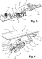
figure 3 est une vue de dessous en perspective d'un mécanisme actionnable mécaniquement de la commande d'ouverture de lafigure 1 ; - la
figure 4 est une vue partielle agrandie de dessus en perspective de la commande d'ouverture ; - la
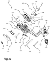
figure 5 est une vue éclatée d'un mécanisme de secours de la commande d'ouverture de lafigure 1 ; - les
figures 6A à 6D représentent des vues en détail d'un organe-moteur de la commande d'ouverture selon l'invention ; - les
figures 7A à 7D représentent des vues en détail d'un rouage de transmission de type à roue libre d'une chaîne cinématique de remontage de la commande d'ouverture selon l'invention : - les
figures 8 et 9 représentent une vue en détail d'un amortisseur rotatif d'une chaîne cinématique d'entraînement de la commande d'ouverture selon l'invention ; - les
figures 10 à 20 illustrent des étapes de fonctionnement de la commande d'ouverture de lafigure 1 .
- the
figure 1 is a perspective view of an opening control according to the invention; - the
figure 2 is an exploded perspective view of the opening command of thefigure 1 ; - the
figure 3 is a bottom view in perspective of a mechanically actuable mechanism of the opening control of thefigure 1 ; - the
figure 4 is an enlarged partial view from above in perspective of the opening control; - the
figure 5 is an exploded view of an emergency mechanism of the opening control of thefigure 1 ; - the
Figures 6A to 6D represent detailed views of a motor member of the opening control according to the invention; - the
Figures 7A to 7D represent detailed views of a gear train of the freewheel type of a kinematic chain for reassembling the opening control according to the invention: - the
Figures 8 and 9 represent a detailed view of a rotary damper of a kinematic chain for driving the opening control according to the invention; - the
figures 10 to 20 illustrate operating steps of the opening control of thefigure 1 .
On a représenté de façon schématique sur la
La commande d'ouverture 10 est prévue pour être montée sur un panneau extérieur (non représenté) de carrosserie d'un ouvrant qui est par exemple une porte latérale de véhicule.The
La commande d'ouverture 10 comporte pour l'essentiel un support fixe ou boîtier 12 présentant une cavité 14 de réception d'une poignée et une poignée 16 montée mobile à l'intérieur de la cavité 14. En service, le support 12 est destiné à être fixé à l'ouvrant. La poignée 16 est dans l'exemple décrit montée articulée par rapport au panneau, autour d'un axe géométrique de pivotement A1, sur le support 12. L'axe de pivotement est en position de service sensiblement vertical et s'étend parallèlement au plan général du panneau extérieur.The
Dans l'exemple illustré, le support 12 a une forme générale parallélépipédique et est adapté pour être logé dans une découpe ou un évidement du panneau extérieur de l'ouvrant de telle manière que sa face extérieure affleure la surface du panneau extérieur de l'ouvrant. Le support 12 est par ailleurs ouvert du côté de sa face extérieure et fermé par un fond du côté intérieur afin de délimiter la cavité 14 destinée à loger la poignée 16.In the example illustrated, the
La poignée 16 est représentée en détail sur la
Dans l'exemple décrit, la poignée 16 est du type « flush », c'est-à-dire que le support 12 sur lequel la poignée 16 est montée mobile forme la cavité 14 apte à recevoir la poignée 16 dans une configuration rentrée. Dans cette configuration rentrée, la surface extérieure de la poignée 16 affleure la surface extérieure de la paroi extérieure de l'ouvrant. En configuration sortie ou déployée, la poignée 16 sort au moins partiellement de la cavité 14 du support 12 de manière à pouvoir être saisie par un utilisateur du véhicule en vue d'ouvrir la porte. Pour ce faire, l'utilisateur peut déplacer en traction la poignée 16 davantage vers l'extérieur afin de commander la serrure de la porte. Dans la position affleurante, la surface extérieure de la commande d'ouverture 10 coïncide avec la surface extérieure de l'ouvrant. Cette disposition affleurante ou « flush », connue dans l'automobile, permet de valoriser le style du véhicule et réduit la traînée aérodynamique.In the example described, the
Il est toutefois entendu que d'autres montages mobiles sont envisageables, comme notamment en pivotement suivant un axe situé à une autre position ou encore en translation suivant une direction essentiellement perpendiculaire au plan moyen de la porte. Il est également à noter que le montage mobile de la poignée par rapport au support est connu en soi de l'homme de métier.It is understood, however, that other mobile assemblies can be envisaged, such as in particular for pivoting along an axis situated in another position or in translation in a direction essentially perpendicular to the mean plane of the door. It should also be noted that the movable mounting of the handle relative to the support is known per se to those skilled in the art.
La commande d'ouverture 10 est destinée à coopérer avec une serrure (non représentée) de l'ouvrant du véhicule automobile susceptible d'adopter une configuration verrouillée et une configuration déverrouillée. De façon classique, le pivotement de la poignée 16 autour de son axe d'articulation A1 actionne la serrure dans l'une ou l'autre de ses deux configurations verrouillée ou déverrouillée par l'intermédiaire d'une chaîne cinématique d'entraînement (non représentée sur les figures).The
A cet effet, comme cela est illustré sur les
Dans l'exemple illustré sur la
On va maintenant décrire en détail la partie électrique 50. Pour son fonctionnement électrique, comme cela est illustré sur la
Ce levier de pivotement 30 a une forme générale d'étrier à travers lequel la portion interne 16.1 de la poignée peut être engagée (
L'étrier d'éjection 30 présente des première et deuxième joues 32 latérales parallèles et perpendiculaires à l'axe commun de rotation A1. Ces joues 32 sont d'une part reliées entre elles par une barrette transversale supérieure 34 destinée à venir en appui contre une paroi d'appui supérieure 40 de la branche interne 16.2 de la poignée 16 et d'autre part par une barrette transversale inférieure 36 qui est destinée à venir en appui contre une paroi d'appui inférieure 42 de la branche interne 16.2 de la poignée 16.The
La commande d'ouverture 10 comprend en outre un organe 38 de rappel relié à l'étrier 30. Cet organe de rappel 38 est configuré pour rappeler l'étrier 30 dans une position de repos correspondant à la configuration affleurante de la poignée 16.The
Cet organe de rappel 38 comprend de préférence un ressort d'étrier pourvu de deux pattes extérieures 44 et d'une partie centrale 46. On voit sur la
Dans l'exemple décrit, la poignée 16 est pourvue d'un organe 28 de rappel de poignée 16 qui est placé entre l'étrier 30 et la portion interne 16.1 de la poignée 16 et qui ont pour axe commun l'axe A1.In the example described, the
Le ressort de rappel de poignée 28 présente deux pattes 48 destinées à être fixées à l'étrier 30 et une partie centrale 49 en prise avec la portion interne 16.2. La fonction du ressort de rappel de poignée 28 est de maintenir un contact entre la portion interne 16.2 de la poignée 16 et l'étrier de pivotement 30, par un effort de rappel et ainsi de rattraper un jeu entre la portion interne 16.1 et l'étrier 30.The
En outre, la partie de fonctionnement électrique 50 comprend dans cet exemple un actionneur électrique 60 relié à un bras 70 d'éjection destiné à s'étendre transversalement à l'intérieur du boîtier 12 de façon pivotante comme cela est visible en
Le bras d'éjection 70 est comme cela est illustré en exemple sur la
Dans le fonctionnement électrique illustré par les
Durant la phase d'éjection de la poignée 16, l'actionneur 60 transmet un mouvement par l'intermédiaire du vérin 62 au bras d'éjection 70. Le bras d'éjection 70 est configuré pour entraîner l'étrier 30 à l'encontre de l'effort de rappel du ressort du levier d'éjection 38, par exemple en appuyant contre la barrette transversale 36 de l'étrier 30. L'étrier 30, qui été maintenu en position de repos par son ressort de rappel 38, est déplacé jusqu'à ce que la poignée 16 atteigne sa position d'éjection. Dans cette position d'éjection, l'utilisateur peut tirer la poignée 16, à l'encontre du ressort 28 de poignée 16, et agir sur le levier de renvoi 20 pour actionner le câble de la serrure. En outre, de préférence, le ressort 28 entre la poignée 16 et l'étrier 30 permet de faire revenir la poignée 16 en position éjectée à la fin de l'action de l'utilisateur en accompagnant le déplacement de l'étrier 30.During the ejection phase of the
Durant la phase de rétraction de la poignée 16, l'actionneur 60 est par exemple alimenté avec une polarité opposée et déplace le bras d'éjection 70 dans le sens inverse. Le bras d'éjection 70 accompagne alors de préférence le mouvement de l'étrier 30 dont le ressort de rappel 38 tend à rappeler dans sa position de repos. La poignée 16 accompagne l'étrier 30 par l'action de son ressort de rappel 28.During the retraction phase of the
L'actionneur 60 est donc dans cet exemple bistable.The
Dans le cas où le fonctionnement électrique s'avère impossible à cause d'une défaillance, la commande d'ouverture 10 comporte conformément à l'invention un mécanisme de secours 100 doté de préférence d'un accumulateur d'énergie élastique. Pour recharger l'accumulateur d'énergie élastique, il faut enfoncer la poignée 16 vers l'intérieur de la carrosserie. Cette action fait pivoter la poignée 16 autour de son axe A1 en opposition à son ressort de rappel 28. Dans le fonctionnement mécanique, de préférence, l'étrier 30 reste immobile. En effet, dans le fonctionnement mécanique manuel, l'étrier 30 reste dans sa position de repos parce qu'il y a un jeu entre l'étrier 30 et la poignée 16 permettant le mouvement de la poignée 16 sans solliciter l'étrier 30.In the event that electrical operation proves impossible due to a failure, the
On va maintenant décrire en détail ce mécanisme 100 qui est illustré sur les
Conformément à l'invention, le mécanisme 100 est actionnable manuellement par enfoncement de la poignée 16 dans une position enfoncée dans le boîtier 12 et est configuré pour entraîner automatiquement et mécaniquement la poignée 16 en mouvement.According to the invention, the
En particulier, le mécanisme 100 est configuré pour être déclenché mécaniquement en réponse à une action d'enfoncement dans le boîtier 12 de la poignée 16, la fin de l'action d'enfoncement étant apte à provoquer le déclenchement du mécanisme 100. Le mécanisme 100 est configuré pour entraîner automatiquement en mouvement la poignée 16 selon tout ou partie d'une course partant d'une position enfoncée de la poignée 16 à la position affleurant en passant par la position éjectée. De préférence, le mécanisme 100 est configuré pour entraîner en mouvement la poignée 16 sur la totalité de la course.In particular, the
Comme cela est illustré en détail sur la
De préférence, l'organe-moteur 110 comprend encore une roue de remontage 118 pourvue d'une denture d'engrenage périphérique. Dans l'exemple illustré sur la
Par ailleurs, le ressort de puissance 112 est placé de façon coaxiale à la roue de remontage 118, qui tourne autour de l'axe A2. Ce ressort-moteur 112 comprend une extrémité extérieure fixée au tambour 116 et une extrémité intérieure fixée à l'arbre de tambour 114. Par exemple, les extrémités extérieure et intérieure du ressort-moteur 112 comprennent chacune un pli configuré pour être reçu à l'intérieur d'une rainure ménagée dans le tambour 116 et dans l'arbre 114. L'arbre 114 comprend par exemple une rainure radiale 113. L'organe-moteur 110 comprend encore dans l'exemple décrit une rondelle de pression 117.Furthermore, the
En outre, le mécanisme 100 comprend encore une chaîne cinématique 120 de remontage de l'organe-moteur 110. Cette chaîne cinématique 120 comprend au moins un moyen 130 de transmission du mouvement d'enfoncement de la poignée 16 à l'organe-moteur 110. De préférence, comme cela est visible sur les
En outre, le moyen 130 est de préférence monté pivotant autour d'un axe A3 par rapport au boîtier 12 et a une forme de secteur circulaire relié de façon pivotante à son extrémité centrale à l'organe de butée d'enfoncement 134 de la poignée 16 et formant à l'autre extrémité un arc de cercle d'engrenage denté 132.In addition, the
A cet effet, de préférence, la chaîne cinématique de remontage 120 comprend un organe poussoir 134 à ressort formant butée d'enfoncement de la poignée 16 et configuré pour impulser un mouvement lors du relâchement de la poignée 16. Le poussoir 134 comprend un manchon 138, une butée élastomérique 139 logée dans le manchon 138 et un ressort de rappel de butée 137. L'extrémité centrale du levier de transmission 130 comprend une fourche 136 à deux bras pour recevoir un axe transversal de pivotement A4 de l'organe de butée 134. L'organe de butée d'enfoncement 134 est destiné à venir en contact avec une face inférieure de la portion externe 16.1 de la poignée 16.To this end, preferably, the winding
Lors de la phase d'enfoncement de la poignée 16 par un utilisateur, le pivotement de la poignée 16 provoque un déplacement de la butée 134, qui glisse vers l'intérieur à l'encontre de son ressort de rappel 137.During the insertion phase of the
L'extrémité inférieure de la butée 144 est liée en rotation au levier de transmission 130 par l'axe A4, de sorte qu'un déplacement de la butée 134 provoque la rotation du levier de transmission 130 autour de son axe A3.The lower end of the
De préférence, le rapport de démultiplication du moyen de transmission 130 à la roue de remontage 118 de l'organe-moteur 110 est défini de telle façon que l'enfoncement de la poignée 16 provoque une rotation angulaire de 2π de la roue de remontage 118.Preferably, the gear ratio of the transmission means 130 to the winding
En outre, la chaîne cinématique de remontage 120 comprend encore un rouage de transmission 140, intercalé entre le moyen de transmission 130 et l'organe-moteur 110. Ce rouage de transmission 140 a pour fonction principale d'empêcher le fonctionnement de la chaîne de remontage 120 dans le sens opposé au sens poignée 16 vers organe-moteur 110.In addition, the winding
A cet effet, le rouage de transmission 140 est unidirectionnel dans le sens poignée vers l'organe-moteur 110. Par exemple, le rouage de transmission unidirectionnel 140 comprend un jeu d'engrenages de type à roue libre. Comme cela est illustré en détail sur les
Ce type d'embrayage est bien connu de l'art antérieur. Par exemple, l'ensemble roue débrayable 140 comporte à cet effet une paire de pignons, un pignon d'engrenage d'entrée 142 et un pignon d'engrenage de sortie 144 coopérant à travers une transmission débrayable de sorte qu'il est possible de transmettre un couple de rotation dans un unique sens de rotation (sens de rotation horaire sur les
En référence aux
- transmettre le couple de l'engrenage d'entrée 142 à l'engrenage de sortie 144, uniquement dans le sens de rotation horaire et par conséquent ne transmettre aucun couple de l'engrenage d'entrée à l'engrenage de sortie, dans un sens de rotation antihoraire,
- ne transmettre aucun couple de l'engrenage de sortie 144 à l'engrenage d'entrée 142, quel que soit le sens de rotation de l'engrenage de sortie 144.
- transmit the torque from the
input gear 142 to theoutput gear 144, only clockwise and therefore do not transmit any torque from the input gear to the output gear, in one direction counterclockwise rotation, - do not transmit any torque from the
output gear 144 to theinput gear 142, regardless of the direction of rotation of theoutput gear 144.
De préférence, les deux pignons 142, 144 sont configurés pour être couplés l'un à l'autre grâce à des éléments d'accouplement respectifs 146, de préférence disposés sur des faces des pignons 142, 144 en regard l'une de l'autre. Les éléments d'accouplement 146 comprennent par exemple deux ou plus de cylindres ou billes, deux ou plus ressorts de rappel des cylindres ou billes, et un tambour 148. Par la suite, on ne décrira un ensemble roue débrayable ne comprenant que deux cylindres.Preferably, the two
L'engrenage de sortie 144 délimite un logement pour recevoir partiellement l'engrenage d'entrée 142 de sorte que l'engrenage d'entrée 142 comporte une paroi latérale externe périphérique laquelle glisse contre la paroi latérale interne périphérique du boîtier. L'engrenage de sortie 144 comporte deux cloisons internes 150 en forme de secteur circulaire. Les deux cylindres 146 sont placés dans l'espace restant entre le tambour et les secteurs circulaires. Les cylindres sont compressés contre les secteurs circulaires par deux ressorts.The
Comme cela est illustré sur les
Le pignon de sortie 144 collabore avec la roue de remontage 118 a travers un engrenage. La démultiplication de la transmission de la poignée 16 et la roue de remontage 118 a été conçue de sorte qu'un enfoncement de la poignée 16 par l'utilisateur entraîne une rotation de 360º de la roue de remontage 118.The
Le mécanisme 100 comprend encore une chaîne cinématique 160 d'entraînement en mouvement de la poignée 16 par l'organe-moteur 110. Cette chaîne cinématique d'entrainement 160 comprend au moins un arbre d'entraînement 170 muni d'un excentrique 172 pour transformer un mouvement rotatif de l'arbre d'entraînement 170 transmis par l'organe-moteur 110 en un mouvement alternatif de pivotement de la poignée 16.The
L'arbre tambour 114 comprend la roue de remontage 118 et une portion terminale d'enroulement 115A du ressort-moteur 112 ainsi qu'une portion terminale d'entraînement 115B destinée à être couplée avec l'arbre d'entraînement 170. Il est bien entendu, que dans l'exemple décrit, le sens de rotation de l'arbre tambour 114 pour remonter le ressort 112 est opposé au sens de rotation de l'arbre tambour 114 pour entraîner l'arbre d'entraînement 170.The
Ainsi, de préférence, l'arbre d'entraînement 170 et l'arbre tambour 114 comprennent des moyens 180 de liaison unidirectionnels en rotation de sorte que lors du remontage de l'organe moteur 110, l'arbre tambour 114 n'entraîne pas en rotation l'arbre d'entraînement 170. De ce fait, l'arbre d'entraînement 170 est solidaire en rotation de l'arbre tambour 114 que dans un seul sens de rotation correspondant au sens de distribution d'énergie de l'organe-moteur 110 par opposition au sens de remontage.Thus, preferably, the
De préférence, les moyens de liaison unidirectionnels 180 comprennent une came 184 et un élément de blocage 182 mobile entre une position active en saillie liée à la came 184 et une position escamotée non liée à la came 184.Preferably, the unidirectional connecting means 180 comprise a
Par exemple, la came 184 est portée par l'arbre de tambour 114 et l'élément de blocage 182 est monté à l'intérieur d'une cage cylindrique 186 conformé en corps de moyeu réceptrice de l'arbre de tambour 114.For example, the
Ainsi, la cage réceptrice cylindrique 186 est conformée en corps de moyeu recevant à l'intérieur la portion terminale d'entraînement 115B de l'arbre tambour 114. Cette cage cylindrique 186 est monté solidaire de l'arbre d'entraînement 170 par une liaison cannelée de type hexagonale 187.Thus, the
Par exemple, l'élément de blocage 182 est monté mobile à l'intérieur de la cage 186 entre une position active d'interaction en saillie à l'intérieur de la cage 186 et une position inactive escamotée tangentiellement à une paroi interne 188 de la cage 186 et la came 184 de l'arbre de tambour 114 est pourvue d'un profil de came pouvant interagir avec l'élément de blocage 182. L'élément de blocage 182 comprend par exemple un cliquet pivotant rappelé élastiquement dans la position d'interaction en saillie par un ressort 189. Par exemple, le profil de came comprend une rampe d'escamotage munie d'une butée terminale 188 contre laquelle le cliquet rotatif 182 vient en prise.For example, the blocking
Le cliquet pivotant 182 de la cage réceptrice 186 permet de transmettre le couple du ressort-moteur de la roue de remontage 118 vers la cage réceptrice 186. Le couple sera transmis une fois que le ressort de puissance 112 est remonté par un tour de la roue de remontage 118. Le cliquet 182 est rappelé contre la came 184 de l'arbre tambour 114 par l'action de son ressort de rappel.The pivoting
Dans la position affleurante et en fin d'enfoncement de la poignée 16, le cliquet rotatif 182 fait face à la butée de la rampe de la came 184, de sorte que la roue de remontage 118 transmet son couple (couple donné par le ressort de puissance) à l'arbre d'entraînement 170 par l'intermédiaire de la cage réceptrice 186.In the flush position and at the end of insertion of the
En outre, la chaîne cinématique d'entraînement 160 comprend encore un moyen 190 d'amortissement de la course du mouvement de rétraction de la poignée 16 depuis sa position éjectée vers sa position affleurante. Le moyen d'amortissement 190 comprend par exemple un amortisseur rotatif configuré pour engrener avec la cage 186 dans le but de réduire la vitesse du mouvement l'excentrique 172 pendant la phase de rétraction et d'éjection de la poignée 16 par le ressort de puissance 112. A cette fin, la cage 186 est pourvue d'une denture périphérique 185 pour coopérer avec l'amortisseur rotatif 190.In addition, the
De façon générale, un amortisseur rotatif peut fonctionner dans un seul sens de rotation ou dans les deux sens de rotation. De préférence, dans le cas présent, afin d'éviter un freinage de la poignée par l'amortisseur rotatif 190 lors de son enfoncement, ce dernier est prévu pour fonctionner uniquement dans la phase de rétraction et d'éjection mais pas pendant l'action d'enfoncement.In general, a rotary damper can operate in one direction of rotation or in both directions of rotation. Preferably, in the present case, in order to avoid braking of the handle by the
La
De préférence, la commande d'ouverture 10 comprend également un moyen 200 de blocage de la chaîne cinématique d'entrainement 160 lors de l'action d'enfoncement. Ainsi, le mécanisme 100 comprend un organe d'arrêt 200 de la transmission de mouvement 160 pendant l'action d'enfoncement.Preferably, the
De préférence, le moyen d'arrêt 200 comprend un cliquet 210 monté pivotant à rappel élastique sur la chaîne cinématique de remontage 120 et un levier de blocage 220 de la chaîne cinématique d'entraînement 160 à basculement entre une position d'arrêt de la chaîne 160 et une position de démarrage, le levier 220 présentant un nez 222 apte à coopérer avec le cliquet de transmission 210 en fin d'action d'enfoncement pour permettre le basculement du levier 220 et le démarrage de la chaîne cinématique d'entraînement 160.Preferably, the stop means 200 comprises a
Le levier d'arrêt 220 comprend également à une extrémité opposée à son nez 222 un crochet 224 apte à venir s'engager dans une encoche 226 ménagée dans la cage réceptrice 186. En effet, le levier d'accrochage 220 est monté pivotant autour d'un axe A7 du boîter de la commande 10 et il est rappelé par un ressort de crochet 228 contre la surface périphérique extérieure de la cage réceptrice 186.The
Dans ce but, comme cela est illustré en détail sur la
On va maintenant décrire en référence aux
Initialement, en mode de fonctionnement électrique, la poignée 16 est en position affleurante (
Lors d'un ordre émis par l'utilisateur, l'actionneur 60 commande la sortie du vérin 62 entraînant le pivotement du bras d'éjection 70. Ce dernier va pousser contre la branche inférieure 36 de l'étrier d'éjection 30 à l'encontre de l'effort de rappel exercé par le ressort de rappel 38 pour accompagner l'éjection de la poignée 16.During an order issued by the user, the
En mode de fonctionnement manuel, la poignée 16 est initialement dans une position affleurante. Cette position est illustrée par exemple par les
L'utilisateur enfonce la poignée 16 de sorte que cette dernière sollicite en compression la butée élastomérique 134 formant organe d'enfoncement. L'enfoncement axial de l'organe poussoir 134 enclenche la chaîne cinématique de remontage.The user pushes the
Ainsi, le levier de transmission pivote (
Dès le relâchement de la poignée 16, la roue libre 140 se place en configuration débrayée et la rotation horaire du levier de transmission 130 (
En outre, le pivotement du levier de transmission 130 pendant l'enfoncement de la poignée 16 permet le rapprochement du cliquet de transmission vers le bec du crochet. Le cliquet de transmission 210 franchit le bec 222 et passe par-dessus le bec 222 du levier de crochet 220 provoquant alors un basculement du crochet 220 et rendant ainsi possible sa libération de la cage réceptrice 186. Pendant l'enfoncement de la poignée 16, le cliquet du levier de transmission 210 se replie (escamote) au contact avec l'extrémité du crochet 224, sans provoquer aucun effet sur le crochet 224. Par contre, cette action positionne le cliquet du levier de transmission 220 dans l'autre coté du crochet 210. De cette manière, quand l'utilisateur arrête l'enfoncement de la poignée 16 et la lâche, le cliquet du levier de transmission 210 frappera le crochet 224 et le libérera.In addition, the pivoting of the
Une fois que le crochet 224 est libéré, la chaîne cinématique d'entraînement 160 démarre et l'arbre d'entraînement 170 tourne librement, entraîné par le ressort de puissance 112.Once the hook 224 is released, the
L'excentrique 172 de l'arbre d'entraînement 170 fait un tour complet. Dans le premier demi-tour, l'excentrique 172 impulsera la poignée 16 vers le haut. Dans le deuxième demi-tour, l'excentrique 172 fera retourner la poignée 16 à sa position initiale.The eccentric 172 of the
Bien entendu, l'invention ne se limite pas aux modes de réalisation précédemment décrits. D'autres modes de réalisation à la portée de l'homme du métier peuvent aussi être envisagés sans sortir du cadre de l'invention définie par les revendications ci-après.Of course, the invention is not limited to the embodiments previously described. Other embodiments within the reach of those skilled in the art can also be envisaged without departing from the scope of the invention defined by the claims below.
Par exemple, il est possible de remonter l'organe-moteur avec plusieurs actions d'enfoncement successives de la poignée. Dans ce cas, la came 184 pourra comprendra plusieurs dents/parois de blocage 388.For example, it is possible to reassemble the motor member with several successive insertion actions of the handle. In this case, the
En plus, la libération de l'arbre excentrique 172 serait réalisée au moment d'atteindre un couple ressort prédéfinie de sorte que l'organe d'arrêt 200 serait formé uniquement par le levier 220. Le levier 220 devra avoir par exemple en extrémité un crochet en forme de V pour permettre sa libération au moment d'atteindre un couple prédéfini du ressort-moteur.In addition, the
Claims (22)
Applications Claiming Priority (1)
| Application Number | Priority Date | Filing Date | Title |
|---|---|---|---|
| FR1870301A FR3078990B1 (en) | 2018-03-16 | 2018-03-16 | MECHANICAL WINDING OPENING CONTROL |
Publications (2)
| Publication Number | Publication Date |
|---|---|
| EP3591150A2 true EP3591150A2 (en) | 2020-01-08 |
| EP3591150A3 EP3591150A3 (en) | 2020-01-15 |
Family
ID=62528759
Family Applications (1)
| Application Number | Title | Priority Date | Filing Date |
|---|---|---|---|
| EP19160955.1A Withdrawn EP3591150A3 (en) | 2018-03-16 | 2019-03-06 | Opening control with mechanical reassembly |
Country Status (5)
| Country | Link |
|---|---|
| US (1) | US11679651B2 (en) |
| EP (1) | EP3591150A3 (en) |
| JP (2) | JP7246201B2 (en) |
| CN (2) | CN110273600B (en) |
| FR (2) | FR3078990B1 (en) |
Families Citing this family (12)
| Publication number | Priority date | Publication date | Assignee | Title |
|---|---|---|---|---|
| JP6957390B2 (en) * | 2018-03-09 | 2021-11-02 | 株式会社アルファ | Vehicle door handle device |
| US11098505B2 (en) * | 2018-10-26 | 2021-08-24 | Inteva Products, Llc | Electrical release for interior compartment (glove box) |
| JP7322165B2 (en) * | 2019-10-16 | 2023-08-07 | 株式会社ユーシン | Door opening/closing detection device and door opening/closing device |
| FR3108137B1 (en) | 2020-03-10 | 2023-03-31 | Akwel Vigo Spain Sl | Motor vehicle door exterior opening control |
| JP7241085B2 (en) * | 2020-04-16 | 2023-03-16 | ウーボ テク カンパニー リミテッド | Flush handle for vehicle door |
| EP3943695B1 (en) * | 2020-07-20 | 2024-04-24 | MINEBEA MITSUMI Inc. | Handle for a vehicle door |
| CN112412185B (en) * | 2020-11-20 | 2021-09-28 | 深圳市威安士电锁有限公司 | Intelligent security electronic lock based on internet system control |
| JP2022118867A (en) * | 2021-02-03 | 2022-08-16 | マツダ株式会社 | vehicle door handle structure |
| EP4124710A1 (en) * | 2021-07-28 | 2023-02-01 | Aisin Corporation | Door handle apparatus for vehicle |
| FR3132121A1 (en) * | 2022-01-24 | 2023-07-28 | Akwel Vigo Spain Sl | Exterior opening control device |
| CN115276550B (en) * | 2022-07-29 | 2023-04-14 | 广东智慧国源新能源科技有限公司 | Photovoltaic board arrangement frame for photovoltaic power generation |
| EP4353931A1 (en) * | 2022-10-14 | 2024-04-17 | Minebea AccessSolutions Italia S.p.A. | Vehicle door handle assembly with a shock absorber |
Family Cites Families (55)
| Publication number | Priority date | Publication date | Assignee | Title |
|---|---|---|---|---|
| JPS4115997Y1 (en) * | 1964-02-07 | 1966-07-25 | ||
| FR2280522B1 (en) | 1974-07-31 | 1977-01-07 | Peugeot & Renault | CONTROL DEVICE FOR RELEASING AND OPERATING SLIDING DOORS BY DOUBLE JOINT PALLET |
| JPH0235110B2 (en) * | 1983-08-26 | 1990-08-08 | Ooi Seisakusho Kk | JIDOSHAYODOAHANDORUSOCHI |
| US4728133A (en) | 1985-06-05 | 1988-03-01 | Unatech | Door handle attachment apparatus |
| GB8627245D0 (en) * | 1986-11-14 | 1986-12-17 | Ford Motor Co | Door handle unit |
| JPH07269177A (en) * | 1994-03-29 | 1995-10-17 | Alpha Corp | Outdoor handle device of retractable type for automobile |
| US5685584A (en) | 1996-05-24 | 1997-11-11 | Katonah Architectural Hardware | Adaptor spindle |
| DE19920511A1 (en) * | 1999-05-05 | 2000-11-09 | Itw Ateco Gmbh | Inner door handle for vehicle has one spring to return the handle into the rest position after opening the door and one spring to control the door locked position |
| US6598913B2 (en) * | 2001-03-01 | 2003-07-29 | Adac Plastics, Inc. | Flush motor vehicle door handle |
| AU2003218648A1 (en) | 2003-02-07 | 2004-08-30 | Otis Elevator Company | Moving flange fastening for passenger conveyors |
| DE102004054189A1 (en) | 2004-11-10 | 2006-05-11 | Bayerische Motoren Werke Ag | Adjustable door knob for motor vehicle, has switching units, and motor drive provided for opening door lock during adjustable movement of knob in one direction, where door lock mechanically opens by adjusting knob in another direction |
| DE102004058874A1 (en) | 2004-12-06 | 2006-06-08 | Huf Hülsbeck & Fürst Gmbh & Co. Kg | Outside door handle for a motor vehicle |
| US7552954B2 (en) | 2006-02-13 | 2009-06-30 | The Boeing Company | Storage bin latch assembly |
| JP4939299B2 (en) * | 2007-05-10 | 2012-05-23 | マツダ株式会社 | Vehicle door handle device |
| FR2941994B1 (en) | 2009-02-09 | 2011-02-11 | Peugeot Citroen Automobiles Sa | DEVICE FOR CONTROLLING THE OPENING OF AN OPENER AND OPENING OF A MOTOR VEHICLE EQUIPPED WITH SUCH A DEVICE |
| DE102009045875A1 (en) * | 2009-10-20 | 2011-04-28 | Huf Hülsbeck & Fürst Gmbh & Co. Kg | Handle device with mechanical reset |
| DE102009045843A1 (en) * | 2009-10-20 | 2011-04-21 | Huf Hülsbeck & Fürst Gmbh & Co. Kg | handle device |
| US8579337B2 (en) | 2010-01-26 | 2013-11-12 | Trimark Corporation | Free floating paddle handle for vehicle doors |
| DE102011001001A1 (en) * | 2010-12-27 | 2012-06-28 | Huf Hülsbeck & Fürst Gmbh & Co. Kg | Outer door handle device for motor car, has loaded energy storage element that loads energy during movement of holding element between stowing away and actuating positions or between operating and open positions in preset chargeable state |
| GB2492319A (en) * | 2011-06-21 | 2013-01-02 | Jaguar Cars | Retractable handle |
| DE102012210278A1 (en) | 2012-06-19 | 2013-12-19 | Bayerische Motoren Werke Aktiengesellschaft | Door inner opener for the door lock of a motor vehicle |
| US8701353B2 (en) * | 2012-06-29 | 2014-04-22 | Ford Global Technologies, Llc | Deployable door handle for vehicles |
| GB2517348B (en) | 2012-09-25 | 2015-09-23 | Jaguar Land Rover Ltd | Retractable handle arrangement |
| JP6009325B2 (en) | 2012-11-12 | 2016-10-19 | アイシン精機株式会社 | Door handle device |
| DE102013017664A1 (en) | 2013-09-27 | 2015-04-02 | Huf Hülsbeck & Fürst Gmbh & Co. Kg | An automobile door handle |
| DE102013112705A1 (en) | 2013-11-18 | 2015-05-21 | Illinois Tool Works Inc. | System of a component and an actuating device for the component |
| FR3023865B1 (en) * | 2014-07-17 | 2016-07-29 | Mgi Coutier Espana Sl | HANDLE ASSEMBLY FOR A MOTOR VEHICLE AND OPENING COMPRISING SUCH A HANDLE ASSEMBLY |
| FR3024173B1 (en) * | 2014-07-25 | 2016-07-29 | Mgi Coutier Espana Sl | HANDLE ASSEMBLY FOR A MOTOR VEHICLE AND OPENING COMPRISING SUCH A HANDLE ASSEMBLY |
| US10563437B2 (en) * | 2014-09-18 | 2020-02-18 | Huf Hülsbeck & Fürst Gmbh & Co. Kg | Flush comfort handle |
| FR3026131B1 (en) * | 2014-09-23 | 2017-06-02 | Mgi Coutier Espana Sl | HIDDEN DOOR HANDLOCK LOCKING DEVICE WITH EMERGENCY MANUAL RELEASE |
| DE102014117005A1 (en) | 2014-11-20 | 2016-05-25 | Witte Automotive Gmbh | Handle arrangement for a door lock |
| DE102014018095A1 (en) * | 2014-12-09 | 2016-06-09 | Huf Hülsbeck & Fürst Gmbh & Co. Kg | Motor vehicle door handle assembly with guide of the handle |
| EP3245364A1 (en) * | 2015-01-16 | 2017-11-22 | BOS GmbH & Co. KG | Motor vehicle door and door handle system therefor |
| KR101637820B1 (en) | 2015-03-24 | 2016-07-07 | 현대자동차주식회사 | Retractable handle system for vehicle |
| GB2536672B (en) | 2015-03-25 | 2018-04-04 | Jaguar Land Rover Ltd | Rectractable handle arrangement with emergency manual deployment |
| DE102015104870A1 (en) * | 2015-03-30 | 2016-10-06 | Huf Hülsbeck & Fürst Gmbh & Co. Kg | Door handle assembly for a motor vehicle |
| JP6458625B2 (en) * | 2015-04-27 | 2019-01-30 | トヨタ車体株式会社 | Vehicle door handle device |
| DE102015011468A1 (en) | 2015-09-01 | 2017-03-02 | Daimler Ag | Locking device for a vehicle door and a vehicle |
| EP3141679B1 (en) | 2015-09-09 | 2020-04-01 | U-Shin Italia S.p.A. | Electronic handle for a vehicle door |
| DE102015115221A1 (en) | 2015-09-10 | 2017-03-16 | Kiekert Ag | Handle of a motor vehicle door handle |
| CN111236770B (en) | 2015-10-21 | 2021-10-26 | 伊利诺斯工具制品有限公司 | Door handle of vehicle |
| JP2017115469A (en) * | 2015-12-25 | 2017-06-29 | アイシン精機株式会社 | Vehicle door handle device |
| DE102016101568A1 (en) | 2016-01-28 | 2017-08-03 | Huf Hülsbeck & Fürst Gmbh & Co. Kg | Door handle system for an electromechanical lock |
| CN105649437B (en) | 2016-03-30 | 2017-12-08 | 宁波华德汽车零部件有限公司 | A kind of concealed automobile external door handle |
| EP3255231A1 (en) | 2016-06-08 | 2017-12-13 | U-Shin Deutschland Zugangssysteme GmbH | Handle for a vehicle door |
| FR3054260B1 (en) * | 2016-07-22 | 2018-07-13 | Peugeot Citroen Automobiles Sa | OPENING OPENING CONTROL SYSTEM FOR MOTOR VEHICLE |
| DE102016113695A1 (en) | 2016-07-25 | 2018-01-25 | Witte Automotive Gmbh | The door handle assembly |
| DE102016217647A1 (en) * | 2016-09-15 | 2018-03-15 | Bos Gmbh & Co. Kg | Door handle system for a vehicle door |
| US10738513B2 (en) | 2016-12-09 | 2020-08-11 | Toyota Motor Engineering & Manufacturing North America, Inc. | Flush power slide door handle |
| FR3060630B1 (en) * | 2016-12-20 | 2019-11-22 | Akwel | AFFLEURANT OPENING CONTROL WITH EJECTION AND MECHANICAL OR ELECTRICAL RETRACTION. |
| DE102017101417A1 (en) | 2017-01-25 | 2018-07-26 | Daimler Ag | Door handle assembly for a vehicle door |
| FR3071861B1 (en) * | 2017-10-03 | 2022-09-30 | Psa Automobiles Sa | MANEUVERING MECHANISM OF A "FLUSH" HANDLE OF AN OPENING VEHICLE OF A MOTOR VEHICLE, AGAINST ITS IMMOBILIZATION IN THE RETRACTED POSITION. |
| DE102017010196B3 (en) | 2017-10-30 | 2019-04-25 | Daimler Ag | Handle device for a motor vehicle door |
| US11332963B2 (en) * | 2018-01-18 | 2022-05-17 | Illinois Tool Works Inc. | Retractable arrangement for actuating a vehicle door with improved ice-breaking function |
| FR3087810B1 (en) * | 2018-10-31 | 2023-02-24 | Psa Automobiles Sa | Sash OPENING CONTROL WITH MULTIPLE EFFORT RETURN |
-
2018
- 2018-03-16 FR FR1870301A patent/FR3078990B1/en active Active
- 2018-12-20 FR FR1873533A patent/FR3078991B1/en active Active
-
2019
- 2019-02-19 JP JP2019027015A patent/JP7246201B2/en active Active
- 2019-03-05 JP JP2019039437A patent/JP7229046B2/en active Active
- 2019-03-06 EP EP19160955.1A patent/EP3591150A3/en not_active Withdrawn
- 2019-03-15 CN CN201910199555.6A patent/CN110273600B/en active Active
- 2019-03-15 CN CN201910199525.5A patent/CN110273601B/en active Active
- 2019-03-18 US US16/356,770 patent/US11679651B2/en active Active
Also Published As
| Publication number | Publication date |
|---|---|
| CN110273600A (en) | 2019-09-24 |
| JP2019157611A (en) | 2019-09-19 |
| JP2019157613A (en) | 2019-09-19 |
| JP7229046B2 (en) | 2023-02-27 |
| EP3591150A3 (en) | 2020-01-15 |
| FR3078990B1 (en) | 2021-01-15 |
| FR3078991B1 (en) | 2022-01-14 |
| FR3078991A1 (en) | 2019-09-20 |
| US11679651B2 (en) | 2023-06-20 |
| CN110273601A (en) | 2019-09-24 |
| CN110273601B (en) | 2022-07-22 |
| JP7246201B2 (en) | 2023-03-27 |
| US20190283555A1 (en) | 2019-09-19 |
| CN110273600B (en) | 2022-08-02 |
| FR3078990A1 (en) | 2019-09-20 |
Similar Documents
| Publication | Publication Date | Title |
|---|---|---|
| EP3591150A2 (en) | Opening control with mechanical reassembly | |
| FR3060630B1 (en) | AFFLEURANT OPENING CONTROL WITH EJECTION AND MECHANICAL OR ELECTRICAL RETRACTION. | |
| EP0313454B1 (en) | Servo-controlled lock with rotary bolt | |
| EP0215702B1 (en) | Electric vehicle door lock | |
| FR3024173A1 (en) | HANDLE ASSEMBLY FOR A MOTOR VEHICLE AND OPENING COMPRISING SUCH A HANDLE ASSEMBLY | |
| EP3581741A1 (en) | Mechanical emergency unlocking opening control | |
| FR3023865A1 (en) | HANDLE ASSEMBLY FOR A MOTOR VEHICLE AND OPENING COMPRISING SUCH A HANDLE ASSEMBLY | |
| EP1769154B1 (en) | Starter motor, particularly for a motor vehicle, provided with a friction free-wheel starter | |
| EP3540157A1 (en) | Linear actuator opening control for motor vehicle | |
| WO2017125653A1 (en) | External opening control of a motor vehicle | |
| FR3001489A1 (en) | ASSEMBLY FOR LOCKING AND UNLOCKING AN ARTICULATING OPENING TO A DORMANT | |
| FR2972972A1 (en) | JOINT SYSTEM AND VEHICLE SEAT COMPRISING SUCH A JOINT SYSTEM | |
| EP3458662A1 (en) | External opening control of a motor vehicle | |
| EP3715565A1 (en) | Opening control with mechanical deployment | |
| EP3511496B1 (en) | Lock for automotive vehicle with three positions | |
| EP3722544A1 (en) | System with handle with safety device | |
| WO2006000667A1 (en) | Starter provided with a friction freewheel drive | |
| EP2575150B1 (en) | Motorization disengagement device of the reset device of the contact closing device in an electric protection apparatus and apparatus comprising same. | |
| EP3670798A1 (en) | Opening control with mechanical reassembly | |
| FR2827341A1 (en) | Automobile starter motor, spigot once meshed with engine crown wheel is stopped from rotating, by a friction, cooperating shape or toothed blocking system | |
| FR3003307A1 (en) | STARTER STARTER HAVING A FRICTION CLUTCH WITH DOUBLE CONTROL LEVERS | |
| FR2905971A1 (en) | Motor vehicle`s lock e.g. mechanical lock, opening assisting system, has spring, whose active end acts on cam in rotation direction of cam for permitting continuous cam rotation and for positioning pawl to disengage pawl from notch of bolt | |
| WO2013124489A1 (en) | Startup control device for a motor vehicle | |
| FR2913257A1 (en) | Clutch controlling device for motor vehicle, has lock for maintaining gear with respect to motor body when coupling unit is in active position, and permitting free rotation of gear with respect to body when unit is in uncoupled position | |
| FR2883906A1 (en) | Motorized driving device for opening and closing e.g. garage door, has motor whose mass presents unbalance around rotation axis to tilt gear in disengaging position when traction arm and snap fastener are in unlocking state |
Legal Events
| Date | Code | Title | Description |
|---|---|---|---|
| PUAI | Public reference made under article 153(3) epc to a published international application that has entered the european phase |
Free format text: ORIGINAL CODE: 0009012 |
|
| PUAL | Search report despatched |
Free format text: ORIGINAL CODE: 0009013 |
|
| AK | Designated contracting states |
Kind code of ref document: A2 Designated state(s): AL AT BE BG CH CY CZ DE DK EE ES FI FR GB GR HR HU IE IS IT LI LT LU LV MC MK MT NL NO PL PT RO RS SE SI SK SM TR |
|
| AX | Request for extension of the european patent |
Extension state: BA ME |
|
| AK | Designated contracting states |
Kind code of ref document: A3 Designated state(s): AL AT BE BG CH CY CZ DE DK EE ES FI FR GB GR HR HU IE IS IT LI LT LU LV MC MK MT NL NO PL PT RO RS SE SI SK SM TR |
|
| AX | Request for extension of the european patent |
Extension state: BA ME |
|
| RIC1 | Information provided on ipc code assigned before grant |
Ipc: E05B 85/10 20140101ALI20191211BHEP Ipc: E05B 81/00 20140101AFI20191211BHEP Ipc: E05B 81/90 20140101ALI20191211BHEP |
|
| STAA | Information on the status of an ep patent application or granted ep patent |
Free format text: STATUS: THE APPLICATION IS DEEMED TO BE WITHDRAWN |
|
| 18D | Application deemed to be withdrawn |
Effective date: 20200716 |