JP7246201B2 - Opening control device with mechanical pop-out mechanism - Google Patents
Opening control device with mechanical pop-out mechanism Download PDFInfo
- Publication number
- JP7246201B2 JP7246201B2 JP2019027015A JP2019027015A JP7246201B2 JP 7246201 B2 JP7246201 B2 JP 7246201B2 JP 2019027015 A JP2019027015 A JP 2019027015A JP 2019027015 A JP2019027015 A JP 2019027015A JP 7246201 B2 JP7246201 B2 JP 7246201B2
- Authority
- JP
- Japan
- Prior art keywords
- door handle
- opening control
- control device
- drive
- lever
- Prior art date
- Legal status (The legal status is an assumption and is not a legal conclusion. Google has not performed a legal analysis and makes no representation as to the accuracy of the status listed.)
- Active
Links
Images


Classifications
-
- B—PERFORMING OPERATIONS; TRANSPORTING
- B60—VEHICLES IN GENERAL
- B60J—WINDOWS, WINDSCREENS, NON-FIXED ROOFS, DOORS, OR SIMILAR DEVICES FOR VEHICLES; REMOVABLE EXTERNAL PROTECTIVE COVERINGS SPECIALLY ADAPTED FOR VEHICLES
- B60J5/00—Doors
- B60J5/04—Doors arranged at the vehicle sides
- B60J5/0412—Lower door structure
- B60J5/0416—Assembly panels to be installed in doors as a module with components, e.g. lock or window lifter, attached thereto
-
- E—FIXED CONSTRUCTIONS
- E05—LOCKS; KEYS; WINDOW OR DOOR FITTINGS; SAFES
- E05B—LOCKS; ACCESSORIES THEREFOR; HANDCUFFS
- E05B81/00—Power-actuated vehicle locks
-
- E—FIXED CONSTRUCTIONS
- E05—LOCKS; KEYS; WINDOW OR DOOR FITTINGS; SAFES
- E05B—LOCKS; ACCESSORIES THEREFOR; HANDCUFFS
- E05B85/00—Details of vehicle locks not provided for in groups E05B77/00 - E05B83/00
- E05B85/10—Handles
- E05B85/103—Handles creating a completely closed wing surface
-
- E—FIXED CONSTRUCTIONS
- E05—LOCKS; KEYS; WINDOW OR DOOR FITTINGS; SAFES
- E05B—LOCKS; ACCESSORIES THEREFOR; HANDCUFFS
- E05B85/00—Details of vehicle locks not provided for in groups E05B77/00 - E05B83/00
- E05B85/10—Handles
- E05B85/107—Pop-out handles, e.g. sliding outwardly before rotation
-
- E—FIXED CONSTRUCTIONS
- E05—LOCKS; KEYS; WINDOW OR DOOR FITTINGS; SAFES
- E05B—LOCKS; ACCESSORIES THEREFOR; HANDCUFFS
- E05B85/00—Details of vehicle locks not provided for in groups E05B77/00 - E05B83/00
- E05B85/10—Handles
- E05B85/14—Handles pivoted about an axis parallel to the wing
- E05B85/16—Handles pivoted about an axis parallel to the wing a longitudinal grip part being pivoted at one end about an axis perpendicular to the longitudinal axis of the grip part
-
- E—FIXED CONSTRUCTIONS
- E05—LOCKS; KEYS; WINDOW OR DOOR FITTINGS; SAFES
- E05B—LOCKS; ACCESSORIES THEREFOR; HANDCUFFS
- E05B81/00—Power-actuated vehicle locks
- E05B81/02—Power-actuated vehicle locks characterised by the type of actuators used
- E05B81/04—Electrical
- E05B81/08—Electrical using electromagnets or solenoids
-
- E—FIXED CONSTRUCTIONS
- E05—LOCKS; KEYS; WINDOW OR DOOR FITTINGS; SAFES
- E05B—LOCKS; ACCESSORIES THEREFOR; HANDCUFFS
- E05B81/00—Power-actuated vehicle locks
- E05B81/54—Electrical circuits
- E05B81/90—Manual override in case of power failure
Description
本発明は、自動車のドアの開制御装置に関する。より具体的には、本発明は、ラッチの電気的作動手段が故障した場合のためのバックアップ用機械的ロック解除手段を備える外部からの開制御装置に関するが、これに限定されない。この開制御装置はまた、従来のラッチ、又は、「電子ラッチ」若しくは「eラッチ」としても知られる電気作動ラッチによるロック解除にも良好に適用される。 The present invention relates to an automobile door opening control device. More particularly, but not exclusively, the present invention relates to an external opening control device with backup mechanical unlocking means in case the latch's electrical actuation means fails. This opening control is also well adapted for unlocking by conventional latches or electrically actuated latches, also known as "electronic latches" or "e-latches".
一般的に、外部開制御装置は、ドアに取り付けられるよう構成された固定支持体と、この支持体上に可動に取り付けられたドアハンドル(例えば、軸を中心として回動可能にヒンジ留めされることにより支持体に回動可能に取り付けられたドアハンドル)と、を備える。 Typically, an external opening control device comprises a fixed support configured to be attached to a door and a door handle (e.g., pivotally hinged about an axis) movably mounted on the support. a door handle pivotably mounted to the support.
開制御装置は、ロック解除機構をさらに備える。ロック解除機構は、ドアハンドルが引っ張られて操作されると、ラッチのロック解除を可能にして、ドアの開放を可能にする。従来、ラッチはドアに固定されたボルトを備え、このボルトは車体に固定されたストライカと協働するよう構成されている。ドアを車両外部から開放すると、外部開制御装置の作動により、ボルトはストライカから解放される。 The open control device further comprises an unlocking mechanism. The unlocking mechanism allows unlocking of the latch and opening of the door when the door handle is pulled and operated. Conventionally, the latch comprises a bolt fixed to the door, which bolt is adapted to cooperate with a striker fixed to the vehicle body. When the door is opened from the outside of the vehicle, the bolt is released from the striker by the operation of the external opening control device.
より具体的には、本発明は、「面一(フラッシュ)」タイプのドアハンドルを備える開制御装置に関するものである。即ち、ドアハンドルが可動に取り付けられた支持体は、ドアハンドルを後退状態で収容するよう構成されたキャビティを形成する。この後退状態では、ドアハンドルの外側表面はドアの外側壁部の外側表面と面一である。突出状態、即ち、展開状態では、ドアハンドルは、支持体のキャビティから少なくとも部分的に突出して、車両のユーザがドアを開放するためにドアハンドルを把持できるようになる。この目的のために、ユーザは、ドアハンドルをさらに外側に変位させることによりドアのラッチを制御できる。 More specifically, the present invention relates to an opening control device with a "flush" type door handle. That is, the support to which the door handle is movably mounted defines a cavity configured to receive the door handle in the retracted position. In this retracted position, the outer surface of the door handle is flush with the outer surface of the outer wall of the door. In the protruded or deployed state, the door handle protrudes at least partially from the cavity of the support so that a user of the vehicle can grasp the door handle to open the door. For this purpose, the user can control the door latch by displacing the door handle further outwards.
一般に、開制御装置は、ドアハンドルを電気的に突出させるための機構を備え、ユーザによるドアハンドルの把持及びドアの開放を可能にする。このような電気的突出機構は、例えば、自動車のバッテリによって供給される電力により動作し、キー、携帯電話、又は遠隔通信を可能にするその他の任意の装置によって遠隔的且つ電子的に制御できる。 Typically, the opening control device includes a mechanism for electrically extending the door handle, allowing the user to grasp the door handle and open the door. Such an electrical projection mechanism may be operated, for example, by power supplied by an automobile battery, and may be remotely and electronically controlled by a key, cell phone, or any other device that allows remote communication.
しかしながら、この電力供給ができない場合には、ドアハンドルを電気的に突出させて使うことができないので、ユーザは車両に乗ることができない。したがって、特にバッテリが電気的突出機構を作動させるのに十分なエネルギーを有していない場合に、車両のドアをロック解除できるようにするバックアップ機構を設けることが必要である。 However, if this power cannot be supplied, the user cannot get into the vehicle because the door handle cannot be electrically protruded. Therefore, it is necessary to provide a backup mechanism that allows the vehicle door to be unlocked, especially when the battery does not have sufficient energy to operate the electrical ejection mechanism.
本発明は、これらの欠点を克服し、簡単な方法で機械的なロック解除をバックアップできるコンパクトで頑丈な開制御装置を提供することを目的とする。 SUMMARY OF THE INVENTION It is an object of the present invention to overcome these drawbacks and to provide a compact and robust opening control device that can back up mechanical unlocking in a simple manner.
この目的を達成するため、本発明は、自動車のドア用の開制御装置を対象とし、この装置は、
ドアに取り付けられるよう構成されたケースと、
少なくとも、ケース内に完全に又は部分的に収容される面一の位置と、少なくとも部分的にケースから突出している突出位置との間で、ケースに対して回動可能に取り付けられたドアハンドルと、
ドアハンドルのケースへの少なくとも1回の押し込み動作に反応して機械的に始動されるよう構成された機構であって、押し込み動作の完了により始動するよう構成された機構と、を備え、
上記機構は、ドアハンドルの押し込み動作中に機械エネルギーを蓄積するとともに押し込み動作の完了時にドアハンドルを動作させるための機械エネルギーを放出するよう構成された駆動部材を備えることにより、ドアハンドルの押し込み位置から突出位置を経過して面一の位置までの行程の全てにわたって又は一部においてドアハンドルを自動的に作動させることを特徴とする。
To achieve this object, the present invention is directed to an opening control device for a motor vehicle door, which device comprises:
a case configured to be attached to a door;
a door handle pivotally mounted relative to the case between at least a flush position in which it is fully or partially contained within the case and a protruding position in which it protrudes at least partially from the case; ,
a mechanism configured to be mechanically activated in response to at least one pushing motion of the door handle into the case, the mechanism configured to be activated upon completion of the pushing motion;
The mechanism comprises a drive member configured to store mechanical energy during a pushing motion of the door handle and to release mechanical energy to move the door handle upon completion of the pushing motion, thereby providing a door handle in a pushed position. The door handle is automatically actuated over all or part of the travel from the protruded position to the flush position.
この手動操作機構のおかげで、電気的支援なしにドアハンドルを突出させることができる。さらに、この機構により、電気的支援なしに、ドアハンドルを面一の位置に自動的に後退させることができる。 Thanks to this manual operating mechanism, the door handle can be extended without electrical assistance. Additionally, this mechanism allows the door handle to automatically retract to a flush position without electrical assistance.
開制御装置は、以下の特徴のうち1つ以上を有していてもよい。 The open control device may have one or more of the following features.
本発明の好ましい実施形態では、機構は、駆動部材と、駆動部材を機械的にポップアウトさせるための運動連鎖機構と、駆動部材によってドアハンドルを機械的に駆動するための運動連鎖機構と、を備える。 In a preferred embodiment of the invention, the mechanism comprises a drive member, a kinematic chain mechanism for mechanically popping out the drive member, and a kinematic chain mechanism for mechanically driving the door handle by the drive member. Prepare.
好ましくは、駆動部材は、ドアハンドルの押し込み動作中に機械エネルギーを蓄積するとともに押し込み動作の完了時にドアハンドルを動作させるための機械エネルギーを放出するよう構成されている。 Preferably, the drive member is arranged to store mechanical energy during the pushing action of the door handle and to release mechanical energy to operate the door handle upon completion of the pushing action.
例えば、駆動部材は、シャフトと、バネケースと、バネケース内に収容され、バネケースシャフトの周りに渦巻き状に巻かれた駆動バネと、を備える。
本発明の好ましい実施形態では、駆動部材は、バネケースシャフトにしっかりと取り付けられた外周の歯を有するポップアウト(飛び出し)歯車を備える。
For example, the drive member comprises a shaft, a spring case, and a drive spring contained within the spring case and spirally wound around the spring case shaft.
In a preferred embodiment of the invention, the drive member comprises a pop-out gear having peripheral teeth rigidly attached to the spring case shaft.
例えば、駆動バネの螺旋部(コイル部)の内側の端部はバネケースシャフトに固定されており、外側の端部はバネケースに固定されている。 For example, the inner end of the helical portion (coil portion) of the drive spring is fixed to the spring case shaft, and the outer end is fixed to the spring case.
本発明の好ましい実施形態では、駆動運動連鎖機構は、ドアハンドルを動作させるためのシャフトを備え、シャフトには、シャフトの回転運動をドアハンドルの交互回動運動に変換するための偏心部が設けられている。 In a preferred embodiment of the invention, the drive kinematics mechanism comprises a shaft for operating the door handle, the shaft being provided with an eccentric for converting rotary motion of the shaft into alternating pivotal motion of the door handle. It is
好ましくは、駆動シャフト及びバネケースシャフトは、一方向に回転可能なリンク手段を備える。 Preferably, the drive shaft and the spring case shaft comprise unidirectionally rotatable linkage means.
例えば、一方向リンク手段は、カムと、カムに係合する突出作動位置とカムに係合しない収容位置との間で可動なブロック要素と、を備える。 For example, the one-way link means comprises a cam and a blocking element movable between a protruding operative position engaging the cam and a retracted position not engaging the cam.
好ましい実施形態では、カムは、バネケースシャフトによって支持され、ブロック要素は、バネケースシャフトを受容するためのハブ本体として形成された円筒形ケージ内に取り付けられる。 In a preferred embodiment, the cam is supported by the spring case shaft and the blocking element is mounted within a cylindrical cage formed as a hub body for receiving the spring case shaft.
好ましくは、ポップアウト運動連鎖機構は、ドアハンドルの押し込み動作を駆動部材へ伝達するための少なくとも1つの伝動手段を備える。 Preferably, the pop-out kinematic chain mechanism comprises at least one transmission means for transmitting the pushing action of the door handle to the drive member.
本発明の好ましい実施形態では、伝動手段は、ケースに回動可能に取り付けられたレバーであり、レバーは、一端がドアハンドルの押し込み止め部材に回動可能に連結され、他端が歯車の円弧を形成する扇形になっている。 In a preferred embodiment of the invention, the transmission means is a lever rotatably mounted on the case, the lever being rotatably connected at one end to the push-stop member of the door handle and at the other end being a gear arc. It forms a fan shape.
好ましくは、伝動手段から駆動部材への伝達比は、ドアハンドルを押し込むことにより、駆動部材のポップアウト歯車を2πの角度分だけ回動させるように規定されている。 Preferably, the transmission ratio from the transmission means to the drive member is defined such that pushing in the door handle causes the pop-out gear of the drive member to rotate by an angle of 2π.
好ましくは、機構は、押し込み動作中に駆動運動連鎖機構を停止させる手段を備える。 Preferably, the mechanism comprises means for stopping the drive kinematic mechanism during the pushing motion.
好ましい実施形態では、停止手段は、ポップアウト運動連鎖機構に回動可能に取り付けられた弾性付勢伝動爪と、駆動運動連鎖機構の停止位置と始動位置との間で傾斜するように取り付けられた駆動運動連鎖機構をブロックするためのブロックレバーと、を備える。ブロックレバーは、突端部又は先端部又は指部を有し、この突端部又は先端部又は指部は、押し込み動作完了時に伝動爪と係合して、駆動運動連鎖機構の停止位置から始動位置までブロックレバーを傾斜させることができるよう構成されている。 In a preferred embodiment, the stop means is a resiliently biased transmission pawl pivotally mounted on the pop-out kinematic chain and mounted to tilt between a stop position and a start position of the drive kinematic chain. a blocking lever for blocking the drive kinematic mechanism. The block lever has a tip or tip or finger that engages the transmission pawl when the pushing motion is completed to move the drive kinematic chain mechanism from the stop position to the start position. It is configured so that the block lever can be tilted.
例えば、ポップアウト運動連鎖機構は、ドアハンドルから駆動部材への方向の一方向伝動歯車列を備え、一方向伝動歯車列は具体的にはフリー歯車型である。 For example, the pop-out kinematic chain mechanism comprises a one-way transmission gear train in the direction from the door handle to the drive member, and the one-way transmission gear train is specifically of free gear type.
好ましくは、フリー歯車は、対応する連結要素によって少なくとも1つの方向に回転するように互いに連結された一対の歯付ピニオンを含む一方向クラッチを備える。 Preferably, the free gear comprises a one-way clutch comprising a pair of toothed pinions interconnected for rotation in at least one direction by corresponding coupling elements.
好ましい実施形態では、駆動運動連鎖機構は、ドアハンドルの行程を少なくとも突出位置から面一の位置までにおいて制動するよう構成された制動部材を備える。 In a preferred embodiment, the drive kinematics mechanism comprises a braking member configured to brake the travel of the door handle at least from the extended position to the flush position.
好ましくは、開制御装置は、ドアハンドルを回動させて突出及び/又は後退させるレバーと、回動レバーを電気的に作動させるための手段と、をさらに備える。 Preferably, the opening control device further comprises a lever for rotating the door handle to extend and/or retract, and means for electrically actuating the rotating lever.
好ましくは、レバーは、内側にドアハンドルが係合可能なブラケット形状を有し、ドアハンドルの上部軸受壁に当接する少なくとも1つの上側クロスバーと、ドアハンドルの下部軸受壁に当接する下側クロスバーと、を備え、レバーは、レバーを弾性的に戻すための部材を備える。 Preferably, the lever has a bracket shape inside which the door handle can be engaged, and has at least one upper cross bar abutting the upper bearing wall of the door handle and a lower cross bar abutting the lower bearing wall of the door handle. a bar, the lever comprising a member for elastically returning the lever.
別の好ましい実施形態では、駆動運動連鎖機構のブロックレバーは、駆動運動連鎖機構の停止位置と始動位置との間で傾斜するように取り付けられ、ブロックレバーは、駆動部材の所定のポップアウトバネトルク閾値を超えるときに始動位置へ傾斜するよう構成されている。 In another preferred embodiment, the blocking lever of the drive kinematic chain is mounted to tilt between the stop and start positions of the drive kinematic chain, the blocking lever being biased against a predetermined pop-out spring torque of the drive member. It is configured to tilt to the starting position when the threshold is exceeded.
好ましくは、ポップアウト運動連鎖機構は、ドアハンドルの押し込み止めを形成するバネを有するプッシュ部材を備え、バネは、ドアハンドルを解放するときに動作を促すよう構成されている。 Preferably, the pop-out kinematic chain mechanism comprises a push member having a spring forming a push stop for the door handle, the spring being configured to urge movement when releasing the door handle.
好ましい実施形態では、回動レバーは、駆動部材によるドアハンドルのポップアウト中及び機械的駆動中に動かないように維持される。 In a preferred embodiment, the pivot lever is kept stationary during pop-out of the door handle by the drive member and during mechanical actuation.
本発明の他の特徴及び利点は、添付図面を参照してなされる以下の説明により明らかになるであろう。 Other features and advantages of the present invention will become apparent from the following description made with reference to the accompanying drawings.
図1には、本発明に係る自動車のドア用の開制御装置が概略的に示されている。この開制御装置は、全体を通して、参照符号10で示される。
FIG. 1 schematically shows an opening control device for a motor vehicle door according to the invention. This opening control is indicated throughout with the
開制御装置10は、例えば車両のサイドドアであるドアの車体外側パネル(図示せず)に搭載されるよう構成されている。
The
開制御装置10は、主に、ドアハンドルを収容するためのキャビティ14を有する固定支持体(ケース)12と、キャビティ14の内部に可動に取り付けられたドアハンドル16と、を備える。支持体12は、使用時には、ドアに固定されるよう構成されている。記載される例では、ドアハンドル16は、支持体12に、幾何学的な回動軸A1を中心としてパネルに対してヒンジ式に取り付けられる。使用位置において、回動軸A1は略鉛直であり、外側パネルの概略的平面に対して平行に延びる。
The
図示の例では、支持体12の概略的形状は平行六面体である。この支持体12は、その外側表面がドアの外側パネルの面と面一になるように、ドアの外側パネルの切欠き又は凹部内に収容されるよう構成されている。さらに、支持体12は、外側表面に開口部を有し、内側は底面によって閉鎖されており、これにより、ドアハンドル16を収容するよう構成されたキャビティ(ハウジング)14を規定している。
In the illustrated example, the general shape of the
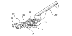
ドアハンドル16は、図2に詳細に示されている。ドアハンドル16は、ユーザによって把持可能な外側部分16.1を有する。ドアハンドル16は、外側部分16.1と反対側に、内側部分16.2を有する。内側部分16.2は、図2に示すように支持体を構成するケース12のハウジング14内に延びるよう構成されている。従来、ドアハンドル16は、外側部分16.1に、通常平坦で細長い形状を有するグリップフラップ18を含む。
Door handle 16 is shown in detail in FIG. The
記載された例では、ドアハンドル16は「面一(フラッシュ)」タイプのものである。即ち、ドアハンドル16が可動に取り付けられた支持体12は、ドアハンドル16を後退状態で収容するよう構成されたキャビティ14を形成する。この後退状態では、ドアハンドル16の外面はドアの外側壁部の外側表面と面一である。突出状態、即ち、展開状態では、ドアハンドル16は、支持体12のキャビティ14から少なくとも部分的に突出し、車両のユーザはドアハンドル16を把持してドアを開けることができる。この目的のために、ユーザは、引っ張った状態のドアハンドル16をさらに外側に変位させて、ドアのラッチを制御できる。面一の位置では、開制御装置10の外側表面はドアの外側表面と一致している。自動車産業において公知のこの「面一」配置により、車両のスタイルに付加価値が与えられ、空力抵抗が小さくなる。
In the example described, the
しかしながら、例えば、別の位置にある軸を中心として回動させること、又は、ドアの概略的平面に実質的に垂直な方向に沿って並進させることにより、他の可動式取付も想定され得る。なお、支持体に対してドアハンドルを可動に取り付けること自体は、当業者に公知である。 However, other movable mountings are also conceivable, for example by pivoting about an axis in another position or by translating along a direction substantially perpendicular to the general plane of the door. It should be noted that movably attaching the door handle to the support itself is known to those skilled in the art.
開制御装置10は、ロック状態及びロック解除状態をとることができる自動車のドアのラッチ(図示せず)と協働するよう構成されている。従来、ヒンジ軸(回動軸)A1を中心としてドアハンドル16を回動させることにより、駆動運動連鎖機構(図示せず)を介して、ラッチを作動させて、ラッチの2つの状態であるロック状態又はロック解除状態のいずれか一方の状態にする。
The
この目的のために、図1及び図2に示すように、開制御装置10は、伝動レバー20を備える。この伝動レバー20は、ここに記載の例では、ロータリーケージ22と、伝動軸24と、このロータリーケージ22内に収容されるよう構成された伝動戻しバネ26と、を備える。ロータリーケージ22は、例えばボーデンケーブル(図示せず)の端部を保持するための手段を備える。これら伝動レバー20の一式は、図1に示すように、支持体12に取り付けられるよう構成されている。
For this purpose, the
図2に示す例では、開制御装置10は、ドアハンドル16の突出及び/又は後退の電気的操作を可能にする電気的部分50と、ドアハンドル16の動きを機械的に操作できる機械的部分(バックアップ機構100)と、を備える。
In the example shown in FIG. 2, the
次に、電気的部分50を詳細に説明する。図2に示すように、開制御装置10は、電気的部分50の電気的動作のために、好ましくは、ドアハンドル16を回動させるための回動レバー30をさらに備える。この回動レバー30は、ドアハンドル16の回動軸A1に取り付けられている。したがって、回動レバー30は、少なくとも1つの共通の回動軸A1によってドアハンドル16に連結されている。
The
この回動レバー30の概略的形状は、ドアハンドルの内側部分16.2を係合可能なクランプ状である(図2)。
The general shape of this pivoting
突出用ブラケット(回動レバー)30は、互いに平行であり且つ共通の回動軸A1に垂直な第1及び第2の側面32を有する。これらの側面32は、ドアハンドル16の内側枝状部(内側部分)16.2の上部軸受壁40に当接するよう構成された上側クロスバー34によって互いに連結され、又、ドアハンドル16の内側枝状部(内側部分)16.2の下部軸受壁42に当接するよう構成された下側クロスバー36によって互いに連結されている。
The projecting bracket (pivoting lever) 30 has first and second side faces 32 which are parallel to each other and perpendicular to the common pivot axis A1. These
開制御装置10は、ブラケット30に連結された戻し部材38をさらに備える。この戻し部材38は、ブラケット30をドアハンドル16の面一状態に対応する静止位置に戻すよう構成されている。
The
この戻し部材38は、好ましくは、中央部分46と2つの外側脚部44とを有するブラケットバネを備える。図2に、ブラケットバネ(戻し部材)38の2つの外側脚部44の各々がケース12の内壁に固定されることを示す。
This
記載された例では、ドアハンドル16には、ドアハンドル16を戻すための部材(ドアハンドル戻しバネ)28が設けられている。この部材(ドアハンドル戻しバネ)28は、ブラケット30とドアハンドル16の内側部分16.2との間に配置され、回動軸A1を共通軸として有する。
In the example described, the
ドアハンドル戻しバネ28は、ブラケット30に固定されるよう構成された2つの脚部48と、内側部分16.2と係合される中央部分49と、を有する。ドアハンドル戻しバネ28の役割は、内側部分16.2と回動ブラケット30との間のクリアランスがある場合に、ドアハンドル16の内側部分16.2と回動ブラケット30との間の接触を戻し力により維持することである。
The door
さらに、電気作動部(電気的部分)50は、この例では、図2に示すように、電気アクチュエータ60を備える。電気アクチュエータ60は、ケース12内を横断する方向に回動可能に延びるよう構成された突出用アーム70に連結されている。電気アクチュエータ60は、好ましくは、突出用アームの端部72と協働する端部64を有する直線状シリンダ62を備える。例えば、端部64は凹部を有し、端部72は突起部を有する。
Furthermore, the electrical actuation part (electrical part) 50 comprises in this example an
図示のように、図2の例では、突出用アーム70は、ケース12の2つの平行なフランジ76の間に回動可能に取り付けられる端部74を有する。
As shown, in the example of FIG. 2, projecting
図10~図13に示す電気的動作において、ユーザは、例えば、自動車の車載コンピュータに対して開指示を与え、この車載コンピュータが電子信号を電気アクチュエータ60に送信する。この指示により、電気アクチュエータ60の直線状シリンダ62が変位する。
In the electrical operation shown in FIGS. 10-13, the user, for example, gives an opening command to the vehicle's on-board computer, which sends an electronic signal to the
ドアハンドル16を突出させる段階では、電気アクチュエータ60は、直線状シリンダ62を介して突出用アーム70へ動きを伝達する。突出用アーム70は、例えばブラケット30の下側クロスバー36を押圧することによって、突出用レバー(戻し部材)38のバネの戻し力に抗してブラケット30を駆動するよう構成されている。戻しバネ(戻し部材)38によって静止位置に保持されていたブラケット30は、ドアハンドル16が突出位置に到達するまで変位させられる。この突出位置では、ユーザはドアハンドル16をドアハンドル16のドアハンドル戻しバネ28に抗して引っ張り、伝動レバー20を介してラッチのケーブルを作動させることができる。また、好ましくは、ドアハンドル16とブラケット30との間のドアハンドル戻しバネ28がブラケット30を変位させることにより、ユーザの操作が完了したときにドアハンドル16を突出位置に戻すことができる。
In the step of extending the
ドアハンドル16を後退させる段階では、電気アクチュエータ60は、例えば、反対の極性で電力供給され、突出用アーム70を逆方向に変位させる。そして、突出用アーム70は、好ましくは、静止位置に戻ろうとする戻しバネ38を有するブラケット30の動作に追随して動作する。ドアハンドル16は、そのドアハンドル戻しバネ28の作用によってブラケット30に追随して動作する。
In the phase of retracting the
したがって、この例では、電気アクチュエータ60は双安定である。
Therefore, in this example, the
故障によって電気的動作ができないことが判明した場合のために、本発明に係る開制御装置10は、好ましくは弾性エネルギー蓄積部が設けられたバックアップ機構(機械的部分)100を備える。弾性エネルギー蓄積部を再装填するためには、ドアハンドル16を車体の内部に向かって押し込まなければならない。この動作により、ドアハンドル16がその戻しバネ28に抗して回動軸A1を中心として回動する。機械的動作においては、ブラケット30は、動かないままであることが好ましい。実際、手動の機械的動作では、ブラケット30はその静止位置に留まる。なぜなら、ブラケット30とドアハンドル16との間にクリアランスがあり、ブラケット30を動かすことなくドアハンドル16を動かすことができるからである。
In case a failure proves that electrical operation is not possible, the
次に、図3~図9に示すこのバックアップ機構100(以下、単に機構100ともいう)を詳細に説明する。 Next, the backup mechanism 100 (hereinafter simply referred to as mechanism 100) shown in FIGS. 3 to 9 will be described in detail.
本発明によれば、機構100は、ドアハンドル16をケース12内の押し込み位置に押し込むことによって手動で作動させることができ、ドアハンドル16を自動的に駆動して機械的に動作させるよう構成されている。
In accordance with the present invention, the
具体的には、機構100は、ケース12内へのドアハンドル16の押し込み動作に反応して機械的に始動されるよう構成され、押し込み動作の完了により、機構100が始動するようにされている。機構100は、ドアハンドル16の押し込み位置から突出位置を経過して面一の位置までの行程の全てにわたって又は一部においてドアハンドル16を自動的に動作させるよう構成されている。好ましくは、機構100は、行程全体にわたってドアハンドル16を動作させるよう構成されている。
Specifically, the
図5及び図6A~図6Dに詳細に示すように、機構100は、好ましくは、駆動部材110を備える。記載された例では、駆動部材110は、例えば、金属薄板が巻かれた渦巻き状の駆動バネ112を含む。駆動部材110は、軸A2に沿ったシャフト114と、バネケース116と、駆動バネ112と、を備える。駆動バネ112は、バネケースシャフト114の周りに渦巻き状に巻かれて、バネケース116内に収容されている。記載された例では、バネケース116は、支持体(ケース)12に固定される。例えば、バネケース116は、この支持体12に溶接又は螺合することによって固定される。
As shown in detail in FIGS. 5 and 6A-6D,
好ましくは、駆動部材110は、外周歯を備えたポップアウト歯車118をさらに備える。図5に示す例では、ポップアウト歯車118は、バネケースシャフト114(好ましくは、バネケースシャフト114の中央部分)にしっかりと取り付けられている。
Preferably,
さらに、駆動バネ112は、軸A2を中心として回動するポップアウト歯車118と同軸に配置されている。この駆動バネ112の外端部はバネケース116に固定されており、内端部はバネケースシャフト114に固定されている。例えば、駆動バネ112の外端部及び内端部の各々は、バネケース116及びシャフト114に形成された溝内に受容されるよう構成された折返し部を有する。例えば、シャフト114は、径方向溝113を含む。記載された例では、駆動部材110は、スラストワッシャ117をさらに備える。
Additionally, the
また、機構100は、駆動部材110をポップアウトさせるための運動連鎖機構120をさらに備える。運動連鎖機構120は、ドアハンドル16の押し込み動作を駆動部材110に伝達するための少なくとも1つの手段(伝動レバー130)を備える。好ましくは、図16及び図17に示すように、伝動レバー130は、直接的に、又は、記載の例のように間接的に、駆動部材110のポップアウト歯車118を回動させるよう構成された歯車部132を備え、ドアハンドル16の押し込みを停止するための押し込み止め部材134にも連結されている。
さらに、伝動レバー130は、好ましくは、ケース12について軸A3周りに回動可能に取り付けられており、扇形をしている。この扇形の伝動レバー130は、その中心端がドアハンドル16の押し込み止め部材134に回動可能に連結され、他端が歯車部132の円弧を形成する。
Further, the
この目的のために、好ましくは、ポップアウト運動連鎖機構120は、バネを有するプッシュ部材(プッシャ、押し込み止め部材、止め部材ともいう)134を備える。バネは、ドアハンドル16の押し込み止めを形成し、ドアハンドル16の解放中の動作を促すよう構成されている。プッシャ134は、スリーブ138と、スリーブ138内に収容された弾性止め具139と、止め部材戻しバネ137と、を備える。伝動レバー130の中心端は、止め部材134の横方向回動軸A4を受容するための2つのアームを有する分岐部136を備える。押し込み止め部材134は、ドアハンドル16の外側部分16.1の下面と接触するよう構成されている。
To this end, the pop-out
ユーザがドアハンドル16を押し込む段階では、ドアハンドル16が回動することにより、止め部材134が変位し、その止め部材戻しバネ137に抗して内側に滑り込む。
When the user pushes in the
止め部材134の下端は、横方向回動軸A4によって伝動レバー130に回転可能に連結されており、この結果、止め部材134の変位により、伝動レバー130はその軸A3周りに回動する。
The lower end of the
好ましくは、駆動部材110のポップアウト歯車118に対する伝動手段(伝動レバー)130の減速比は、ドアハンドル16を押し込むことにより、ポップアウト歯車118が2πの角度分だけ回動するように規定されている。
Preferably, the reduction ratio of the transmission means (transmission lever) 130 to the pop-
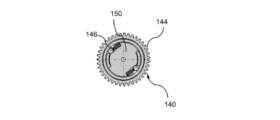
さらに、ポップアウト運動連鎖機構120は、伝動手段(伝動レバー)130と駆動部材110との間に介在された伝動歯車列(一方向伝動歯車列)140をさらに備える。この伝動歯車列140の主な機能は、ポップアウト運動連鎖機構120がドアハンドル16から駆動部材110に向かう方向と反対方向に動作しないようにすることである。
Furthermore, the pop-out
この目的のため、伝動歯車列140はドアハンドルから駆動部材110に向かって一方向にだけ動く。例えば、一方向伝動歯車列140は、フリー歯車を有するタイプの一組の歯車を備える。図7A~図7Dに詳細に示すように、断接歯車又はフリー歯車とも呼ばれる伝動歯車列140は、一方向に回動するように配置された一方向クラッチを備える。
For this purpose, the
このタイプのクラッチは、従来技術において周知である。例えば、断接歯車セット(一方向伝動歯車列)140は、この目的のために、一対のピニオンと、入力ギヤピニオン142と、出力ギヤピニオン144と、を含む。これらのピニオンは、断接トランスミッションを介して協働するので、回転トルクを1つの回転方向(図18~図20における時計回りの回転方向)にのみ伝達することが可能である。
Clutches of this type are well known in the prior art. For example, a disengaging gear set (one-way transmission gear train) 140 includes a pair of pinions, an
図18~図20を参照すると、一方向クラッチ(一方向伝動歯車列)140は、
入力歯車(入力ギヤピニオン)142から出力歯車(出力ギヤピニオン)144へのトルクを時計回りの回転方向のみに伝達し、その結果、入力歯車から出力歯車へのトルクを反時計回りの回転方向に伝達しない機能と、
出力歯車144の回転方向にかかわらず、出力歯車144から入力歯車142へのトルクを伝達しない機能と、を確実に発揮できる。
18 to 20, a one-way clutch (one-way transmission gear train) 140 is
Transmits torque from the input gear (input gear pinion) 142 to the output gear (output gear pinion) 144 only in the clockwise direction of rotation, and consequently does not transmit torque from the input gear to the output gear in the counterclockwise direction of rotation. function and
The function of not transmitting torque from the
好ましくは、2つのピニオン142及び144は、ピニオン142及び144の対向する面にそれぞれ配置されることが好ましい連結要素146によって互いに連結されるよう構成されている。例えば、連結要素146は、2つ以上の円柱部材又はビードと、これらの円柱部材又はビードの2つ以上の戻しバネと、ドラム148と、を備える。次に、2つの円柱部材のみを含む断接歯車セットについて説明する。
Preferably, the two
出力歯車144は、入力歯車142を部分的に受容するためのハウジングを規定し、入力歯車142は、ハウジングの内側壁に対してスリップする外周壁を含む。出力歯車144は、扇形の2つの内側仕切壁150を有する。2つの円柱部材(連結要素)146は、ドラムとこれらの扇形仕切壁との間に残る空間内に配置される。これらの円柱部材は、2つのバネによって扇形仕切壁に対して押圧される。
図18~図20に示すように、伝動レバー130が反時計回りに回動すると、入力ピニオン(入力歯車)142は、時計回りに回動し、出力ピニオン(出力歯車)144を確実に駆動させる。その結果、断接歯車(伝動歯車列)140は、その軸A5を中心として時計回りに回動する単一体として作用する。
As shown in FIGS. 18 to 20, when the
出力ピニオン144は、歯車を介してポップアウト歯車118と相互作用する。ドアハンドル16及びポップアウト歯車118の伝動を減速するように設計されているので、ユーザがドアハンドル16を押し込むと、ポップアウト歯車118が360°(2π)回転する。
機構100は、駆動部材110によってドアハンドル16を動作させる駆動運動連鎖機構160をさらに備える。この駆動運動連鎖機構160は、少なくとも1つの駆動シャフト170を備える。駆動シャフト170には、駆動部材110によって伝達される駆動シャフト170の回転運動をドアハンドル16の交互回動運動に変換するための偏心部172が設けられる。
バネケースシャフト114は、ポップアウト歯車118と、駆動バネ112を巻回するための端部115Aと、駆動シャフト170と連結されるよう構成された駆動端部115Bと、を備える。記載された例では、バネ112をポップアウトさせるためのバネケースシャフト114の回転方向は、駆動シャフト170を駆動するためのバネケースシャフト114の回転方向とは反対であることを理解されたい。
したがって、好ましくは、駆動シャフト170及びバネケースシャフト114は、駆動部材110をポップアウトさせるときに、バネケースシャフト114が駆動シャフト170を回転駆動させることがないように、一方向に回転可能な一方向リンク手段180を備える。よって、駆動シャフト170は、駆動部材110によるエネルギー分布方向(ポップアウト方向とは反対の方向)に相当する1つの回転方向にのみ回転可能なように、バネケースシャフト114に固定される。
Therefore, preferably,
好ましくは、一方向リンク手段180は、カム184とブロック要素182とを備える。ブロック要素182は、カム184と係合する突出作動位置とカム184に係合しない収容位置との間で移動可能である。
Preferably, one-way link means 180 comprises
例えば、カム184は、バネケースシャフト114によって支持され、ブロック要素182は、バネケースシャフト114を受容するためのハブ本体として形成された円筒形の受容ケージ186の内側に取り付けられる。
For example,
したがって、円筒形の受容ケージ186は、バネケースシャフト114の駆動端部115Bをその内部に受容するハブ本体として形成されている。この円筒形の受容ケージ186は、六角形の連結凹部187によって駆動シャフト170にしっかりと取り付けられる。
Cylindrical receiving
例えば、ブロック要素182は、ケージ186内で突出する相互作用作動位置とケージ186の内壁188に対して接線方向に収容される非作動位置との間で可動にケージ186内に取り付けられ、バネケースシャフト114のカム184は、ブロック要素182と相互作用可能なカム形状を有する。例えば、ブロック要素182は、バネ189によって、突出相互作用位置に弾性的に付勢された回動爪を備えている。例えば、カム形状は、回動爪(ブロック要素)182が係合する端部ストッパ(内壁)188を備えた収容傾斜部を含む。
For example, blocking
受容ケージ186の回動爪182により、ポップアウト歯車118の駆動バネから受容ケージ186に向かってトルクを伝達することができる。駆動バネ112がポップアウト歯車118の回動によってポップアウトされると、トルクが伝達される。回動爪182は、その戻しバネの作用によって、バネケースシャフト114のカム184とは反対方向に戻される。
The
面一の位置では、ドアハンドル16の押し込み完了時に、回動爪182はカム184の傾斜部のストッパに対向するので、ポップアウト歯車118は、そのトルク(駆動バネによって与えられるトルク)を受容ケージ186を介して駆動シャフト170に伝達する。
In the flush position, when the
さらに、駆動運動連鎖機構160は、ドアハンドル16を突出位置から面一の位置に向けて後退させる動作の行程を制動するための制動手段190をさらに備える。制動手段190は、例えば、駆動バネ112によるドアハンドル16の後退及び突出の段階における偏心部172の動作速度を低下させるために、ケージ186と噛み合うよう構成された回転ダンパを備える。この目的のために、ケージ186には、回転ダンパ(制動手段)190と協働するための周縁歯185が設けられる。
Further, the
一般に、回転ダンパは、1つの回転方向のみ、又は、両方の回転方向に作動することができる。好ましくは、この例では、ドアハンドルを押し込むときに回転ダンパ190によりドアハンドルが止められないようにするために、回転ダンパ190は、押し込み動作の間ではなく、後退及び突出の段階でのみ作動するよう構成されている。
In general, rotary dampers can operate in only one direction of rotation or in both directions of rotation. Preferably, in this example, the
図9には、回転ダンパ190の詳細を示す。回転ダンパ190は、それ自体公知のように、ケース192と、回動軸周りに回動可能にケース192に取り付けられた回転シャフト194と、ケース192の内側に機能的に介在させた制動手段(例えば、粘性流体又はグリース)と、歯車196とを備える。ケース192は、例えば、締結手段198をさらに備える。
FIG. 9 shows details of the
好ましくは、開制御装置10は、押し込み動作中に駆動運動連鎖機構160をブロックするための停止手段200も備える。即ち、機構100は、押し込み動作中に動作伝達部(駆動運動連鎖機構)160を停止させるための部材(停止手段200)を備える。
Preferably, the
好ましくは、停止手段200は、ポップアウト運動連鎖機構120に回動可能に取り付けられた弾性付勢伝動爪210と、駆動運動連鎖機構160をブロックする停止レバー220と、を備える。この停止レバー220は、駆動運動連鎖機構160の停止位置と始動位置との間で傾斜するよう構成されている。また、この停止レバー220は、押し込み動作の完了時に伝動爪210と協働することにより停止レバー220を傾斜させるとともに駆動運動連鎖機構160を始動させるよう構成された先端部222を有する。
Preferably, the stopping means 200 comprises a resiliently
停止レバー220は、その先端部222とは反対側の一端に、受容ケージ186に形成された凹部226内に係合するよう構成されたフック224を備える。実際、フックレバー(停止レバー220)は、開制御装置10のケースの軸A7周りに回動可能に取り付けられており、フックバネ228によって受容ケージ186の外周面に当接しながら元の位置に戻される。
Stop
この目的のために、図5に詳細に示すように、伝動爪210が、弾性戻しバネ212を用いて伝動レバー130に回動可能に取り付けられている。フック224は、ユーザがドアハンドル16の押し込みを停止するとき、及び、伝動レバー130がドアハンドル16の押し込み方向とは反対方向に回動を開始するとき、停止バネ(止め部材戻しバネ)137の作用により凹部226から解放される。
For this purpose, a
次に、図10~図20を参照して、本発明に係る開制御装置の動作の主要な態様を説明する。図10~図13は、開制御装置10の電気的動作を示しており、図14~図20は、開制御装置10の手動操作を示している。
Principal aspects of the operation of the opening control device according to the present invention will now be described with reference to FIGS. 10 to 20. FIG. 10-13 illustrate the electrical operation of the
最初、電気動作モードでは、ドアハンドル16は面一の位置にある(図12及び図13)。この位置では、突出用ブラケット30は、戻り位置に戻され、ドアハンドル16を面一の位置に保持している。突出用アーム70は、レバーの下側枝部36に当接し、電気アクチュエータ60の直線状シリンダ62は、後退位置にある。
Initially, in the electric mode of operation, the
ユーザの指示に応じて、電気アクチュエータ60は、直線状シリンダ62の突出を制御して、突出用アーム70を回動させる。突出用アーム70が、戻しバネ38によって加えられる戻し力に抗して突出用ブラケット30の下側枝部(クロスバー)36を押すことにより、ドアハンドル16が突出する。
In response to a user's instruction, the
手動操作モードでは、ドアハンドル16は、まず面一の位置にある。この位置は、例えば、図14、図16及び図18に示されている。
In the manual operating mode, the
ユーザがドアハンドル16を押し込むことにより、ドアハンドル16は、押し込み部材を形成する弾性を有する止め部材134を押圧する。押し込み部材134を軸方向に押し込むことにより、ポップアウト運動連鎖機構を始動させる。
As the user pushes on the
したがって、伝動レバーは、クラッチ状態のフリー歯車(伝動歯車列)140を時計回りに駆動するとともにポップアウト歯車118を反時計回りに駆動することによって、軸心の周りを反時計回りに回動する(図19)。この減速比は、ドアハンドル16を押し込むことによりポップアウト歯車118が1回転するように選択される。
Therefore, the transmission lever rotates counterclockwise about the axis by driving the clutched free gear (transmission gear train) 140 clockwise and driving the pop-
ドアハンドル16が解放される場合、フリー歯車(伝動歯車列)140はクラッチ解除位置になり、止め部材134の戻しバネによって伝動レバー130を時計回り方向に回転させても(図20)、ポップアウト歯車118にはトルクは伝達されない。
When the
さらに、ドアハンドル16を押し込む間に伝動レバー130を回動させることにより、伝動爪をフックの突端部に接近させることができる。伝動爪210は、フックレバー(停止レバー)220の突端部222を通過し、突端部222の上方に進み、その後、フックレバー220を傾斜させることにより、受容ケージ186から解放される。ドアハンドル16を押し込んでいる間、伝動レバー130の伝動爪210は、フック224に作用することなくフック224の端部と接触することにより折り返される(格納される)。これに対して、この動作により、伝動レバー130の伝動爪210がフック224の他方の側に位置決めされる。このようにして、ユーザがドアハンドル16を押し込むのを止めてドアハンドル16を解放すると、伝動レバー130の伝動爪210はフック224に当たり、それを解放する。
Further, by rotating the
フック224が解放されると、駆動運動連鎖機構160は始動し、駆動シャフト170は、駆動バネ112によって駆動されて自由に回動する。
When
駆動シャフト170の偏心部172は1回転する。最初の半回転では、偏心部172はドアハンドル16を上方へ付勢する。次の半回転では、偏心部172はドアハンドル16をその初期位置に戻す。
The
もちろん、本発明は、前述の実施形態に限定されるものではない。当業者の範囲内の他の実施形態もまた、以下の特許請求の範囲によって規定される本発明の範囲から逸脱することなく、なお考慮され得る。 Of course, the invention is not limited to the embodiments described above. Other embodiments within the purview of those skilled in the art may still be considered without departing from the scope of the invention as defined by the following claims.
例えば、ドアハンドルの押し込み動作を複数回連続して行うことにより、駆動部材をポップアウトさせることが可能である。この場合、カム184は、いくつかのブロック歯/壁188を備えてもよい。
For example, it is possible to pop out the drive member by performing a plurality of successive pushing movements of the door handle. In this case,
さらに、停止部材200がフックレバー220のみによって構成されるように、所定のバネトルクに到達する時点で偏心シャフト(偏心部材)172を解放させてもよい。例えば、レバー220は、駆動バネの所定のトルクに到達する時点で解放できるように、一方の端部にV字形フックを有していてもよい。
Furthermore, the eccentric shaft (eccentric member) 172 may be released when a predetermined spring torque is reached so that the stopping
Claims (21)
前記自動車のドアに取り付けられるよう構成されたケース(12)と、
少なくとも、前記ケース(12)内に完全に又は部分的に収容される面一の位置と、少なくとも部分的に前記ケース(12)から突出している突出位置との間で、前記ケース(12)に対して回動可能に取り付けられたドアハンドル(16)と、
前記ドアハンドル(16)の前記ケース(12)への少なくとも1回の押し込み動作に反応して機械的に始動されるよう構成された機構(100)であって、押し込み動作の完了により始動するよう構成された機構(100)と、を備え、
前記機構(100)は、前記ドアハンドル(16)の押し込み動作中に機械エネルギーを蓄積するとともに前記押し込み動作の完了時に前記ドアハンドル(16)を動作させるための機械エネルギーを放出するよう構成された駆動部材(110)を備えることにより、前記ドアハンドル(16)の押し込み位置から突出位置を経過して面一の位置までの行程の全てにわたって前記ドアハンドル(16)を自動的に作動させるように構成されており、
前記駆動部材(110)は、
シャフト(114)を有するバネケース(116)と、
前記バネケース(116)内に収容され、前記シャフト(114)の周りに渦巻き状に巻かれた駆動バネ(112)と、を備えている
ことを特徴とする開制御装置(10)。 An opening control device (10) for a door handle of a motor vehicle, comprising:
a case (12) configured to be attached to a door of the motor vehicle;
at least in said case (12) between a flush position in which it is fully or partially contained within said case (12) and a protruding position in which it protrudes at least partially from said case (12); a door handle (16) pivotally mounted relative to;
A mechanism (100) configured to be mechanically activated in response to at least one pushing motion of said door handle (16) into said case (12), said mechanism (100) being activated upon completion of said pushing motion. a configured mechanism (100);
The mechanism (100) is configured to store mechanical energy during a pushing motion of the door handle (16) and to release mechanical energy to operate the door handle (16) upon completion of the pushing motion. A drive member (110) is provided to automatically operate the door handle (16) throughout its entire travel from a pushed position to a flush position through an extended position. is configured as
The drive member (110) is
a spring case (116) having a shaft (114);
a drive spring (112) contained within the spring case (116) and spirally wound around the shaft (114).
An opening control device (10) characterized by:
ことを特徴とする、請求項1に記載の開制御装置(10)。 2. An opening control device (10) according to claim 1 , characterized in that said drive member (110) comprises a gear (118) having peripheral teeth rigidly attached to a shaft (114) of said spring case. ).
ことを特徴とする、請求項1又は2に記載の開制御装置(10)。 4. The claim characterized in that the inner ends of the turns of the drive spring (112) are fixed to the shaft (114) of the spring case and the outer ends thereof are fixed to the spring case (116). 3. An opening control device (10) according to claim 1 or 2 .
ことを特徴とする、請求項1~3のいずれか1項に記載の開制御装置(10)。 The mechanism (100) includes a pop-out kinetic chain mechanism (120) for mechanically popping out the drive member (110) and mechanically driving the door handle (16) by the drive member (110). 4. The opening control device (10) according to any one of the preceding claims, characterized in that it comprises a drive kinematic chain mechanism (160) for .
ことを特徴とする、請求項4に記載の開制御装置(10)。 Said drive kinematics mechanism (160) comprises a drive shaft (170) for operating said door handle (16), said drive shaft (170) having rotary motion of said drive shaft (170) coupled to said door. 5. Opening control (10) according to claim 4 , characterized in that an eccentric (172) is provided for converting the alternating pivoting movement of the handle (16).
ことを特徴とする、請求項5に記載の開制御装置(10)。 Opening control device (10) according to claim 5 , characterized in that said drive shaft (170) and said spring case shaft (114) comprise unidirectionally rotatable unidirectional link means (180). .
ことを特徴とする、請求項6に記載の開制御装置(10)。 Said one-way link means (180) includes a cam (184) provided with at least one cam wall (188) and a protruding operating position engaging said cam wall (188) and engaging said cam (184). 7. An opening control device (10) according to claim 6 , characterized in that it comprises a blocking element (182) movable between a retracted position and a retracted position.
ことを特徴とする、請求項7に記載の開制御装置(10)。 Said cam (184) is supported by said spring case shaft (114) and said blocking element (182) is a cylindrical receiving cage formed as a hub body for receiving said spring case shaft (114). 186) .
ことを特徴とする、請求項4~8のいずれか1項に記載の開制御装置(10)。 The pop-out kinematic chain mechanism (120) comprises a push member (134) having a spring forming a detent of the door handle (16), the spring acting when releasing the door handle (16). Opening control device (10) according to any one of claims 4 to 8 , characterized in that it is arranged to prompt the
ことを特徴とする、請求項4~9のいずれか1項に記載の開制御装置(10)。 4. Claim characterized in that said pop-out kinematic chain mechanism (120) comprises at least one transmission means (130) for transmitting the pushing action of said door handle (16) to said drive member (110). 10. An opening control device (10) according to any one of claims 4 to 9 .
ことを特徴とする、請求項10に記載の開制御装置(10)。 The transmission means (130) is a transmission lever rotatably attached to the case (12), and one end of the transmission lever is rotatable to the push member (134) of the door handle (16). 11. The opening control device (10) according to claim 10 , characterized in that it is connected and the other end is fan-shaped forming the arc of the gear (132).
ことを特徴とする、請求項10又は11に記載の開制御装置(10)。 The transmission ratio from the transmission means (130) to the drive member (110) is such that by pushing the door handle (16), the gear (118) with outer peripheral teeth of the drive member (110) is rotated by an angle of 2π. 12. The opening control device (10) according to claim 10 or 11 , characterized in that it is defined to rotate by .
ことを特徴とする、請求項4~12のいずれか1項に記載の開制御装置(10)。 13. The device according to any one of claims 4 to 12 , characterized in that said mechanism (100) comprises blocking means (200) for blocking said drive kinematic mechanism (160) during said pushing movement. An opening control (10).
前記レバー(220)は先端部(222)を有し、前記先端部(222)は、前記ドアハンドル(16)を解放するときに前記弾性付勢伝動爪(210)と協働して、前記駆動運動連鎖機構(160)の前記停止位置から前記始動位置まで前記レバー(220)を傾斜させることができるよう構成されている
ことを特徴とする、請求項13に記載の開制御装置(10)。 The blocking means (200) comprises an elastic biasing transmission pawl (210) rotatably attached to the pop-out kinematic chain mechanism (120), and a stop position and a starting position of the drive kinematic chain mechanism (160). a lever (220) for blocking the drive kinematic mechanism (160) mounted to tilt between
Said lever (220) has a tip (222), said tip (222) cooperates with said elastically biased transmission pawl (210) when releasing said door handle (16), said 4. An opening control device (10) according to claim 13 , characterized in that it is adapted to allow the lever (220) to be tilted from the stop position to the start position of the drive kinematics mechanism (160). ).
ことを特徴とする、請求項13に記載の開制御装置(10)。 Said blocking means (200) comprises a lever for blocking said drive kinematic mechanism (160) mounted to tilt between a stop position and a start position of said drive kinematic mechanism (160), said lever 4. An opening control device (10) according to claim 13 , characterized in that is arranged to tilt to said starting position when a predetermined pop-out spring torque threshold of said drive member (110) is exceeded. .
ことを特徴とする、請求項4~15のいずれか1項に記載の開制御装置(10)。 The pop-out kinematic chain mechanism (120) comprises a one-way transmission gear train (140) in the direction from the door handle (16) to the drive member (110).
The opening control device (10) according to any one of claims 4 to 15 , characterized in that:
ことを特徴とする、請求項16に記載の開制御装置(10)。 Said one-way transmission gear train (140) comprises a one-way clutch comprising a pair of toothed pinions (142, 144) coupled together for rotation in at least one direction by corresponding coupling elements (146). 17. An opening control device (10) according to claim 16 , characterized in that:
ことを特徴とする、請求項4~17のいずれか1項に記載の開制御装置(10)。 The drive kinematics mechanism (160) comprises a braking member (190) configured to brake the travel of the door handle (16) at least from the protruding position to the flush position, An opening control device (10) according to any one of claims 4 to 17 .
ことを特徴とする、請求項1~18のうちいずれか1項に記載の開制御装置(10)。 The door handle (16) is characterized by comprising a rotating lever (30) for rotating the door handle (16) to protrude and/or retreat, and means (60) for electrically operating the rotating lever (30). The opening control device (10) according to any one of claims 1 to 18 , wherein the opening control device (10)
ことを特徴とする、請求項19に記載の開制御装置(10)。 Said pivot lever (30) has a bracket shape inside which said door handle (16) can be engaged, and at least one upper cross bar (34) abutting on an upper bearing wall of said door handle (16). and a lower crossbar (36) abutting against the lower bearing wall of said door handle (16), said pivoting lever (30) for elastically returning said pivoting lever (30). 20. Opening control (10) according to claim 19 , characterized in that it comprises a member (38).
ことを特徴とする、請求項19又は20に記載の開制御装置(10)。 20 or 20, characterized in that said pivoting lever (30) is kept stationary during pop-out and during mechanical actuation of said door handle (16) by said actuation member ( 110 ); 21. An opening control device (10) according to claim 20 .
Applications Claiming Priority (2)
| Application Number | Priority Date | Filing Date | Title |
|---|---|---|---|
| FR1870301 | 2018-03-16 | ||
| FR1870301A FR3078990B1 (en) | 2018-03-16 | 2018-03-16 | MECHANICAL WINDING OPENING CONTROL |
Publications (2)
| Publication Number | Publication Date |
|---|---|
| JP2019157611A JP2019157611A (en) | 2019-09-19 |
| JP7246201B2 true JP7246201B2 (en) | 2023-03-27 |
Family
ID=62528759
Family Applications (2)
| Application Number | Title | Priority Date | Filing Date |
|---|---|---|---|
| JP2019027015A Active JP7246201B2 (en) | 2018-03-16 | 2019-02-19 | Opening control device with mechanical pop-out mechanism |
| JP2019039437A Active JP7229046B2 (en) | 2018-03-16 | 2019-03-05 | Automotive opening control device with linear actuator |
Family Applications After (1)
| Application Number | Title | Priority Date | Filing Date |
|---|---|---|---|
| JP2019039437A Active JP7229046B2 (en) | 2018-03-16 | 2019-03-05 | Automotive opening control device with linear actuator |
Country Status (5)
| Country | Link |
|---|---|
| US (1) | US11679651B2 (en) |
| EP (1) | EP3591150A3 (en) |
| JP (2) | JP7246201B2 (en) |
| CN (2) | CN110273600B (en) |
| FR (2) | FR3078990B1 (en) |
Families Citing this family (12)
| Publication number | Priority date | Publication date | Assignee | Title |
|---|---|---|---|---|
| JP6957390B2 (en) * | 2018-03-09 | 2021-11-02 | 株式会社アルファ | Vehicle door handle device |
| US11098505B2 (en) * | 2018-10-26 | 2021-08-24 | Inteva Products, Llc | Electrical release for interior compartment (glove box) |
| US20220396981A1 (en) * | 2019-10-16 | 2022-12-15 | U-Shin Ltd. | Door opening/closing detection apparatus and door opening/closing apparatus |
| FR3108137B1 (en) | 2020-03-10 | 2023-03-31 | Akwel Vigo Spain Sl | Motor vehicle door exterior opening control |
| US11525292B2 (en) | 2020-04-16 | 2022-12-13 | Woobo Tech Co., Ltd. | Flush handle for door of vehicle |
| EP3943695B1 (en) * | 2020-07-20 | 2024-04-24 | MINEBEA MITSUMI Inc. | Handle for a vehicle door |
| CN112412185B (en) * | 2020-11-20 | 2021-09-28 | 深圳市威安士电锁有限公司 | Intelligent security electronic lock based on internet system control |
| JP2022118867A (en) * | 2021-02-03 | 2022-08-16 | マツダ株式会社 | vehicle door handle structure |
| EP4124710A1 (en) * | 2021-07-28 | 2023-02-01 | Aisin Corporation | Door handle apparatus for vehicle |
| FR3132121A1 (en) * | 2022-01-24 | 2023-07-28 | Akwel Vigo Spain Sl | Exterior opening control device |
| CN115276550B (en) * | 2022-07-29 | 2023-04-14 | 广东智慧国源新能源科技有限公司 | Photovoltaic board arrangement frame for photovoltaic power generation |
| EP4353931A1 (en) * | 2022-10-14 | 2024-04-17 | Minebea AccessSolutions Italia S.p.A. | Vehicle door handle assembly with a shock absorber |
Citations (3)
| Publication number | Priority date | Publication date | Assignee | Title |
|---|---|---|---|---|
| JP2015533964A (en) | 2012-09-25 | 2015-11-26 | ジャガー・ランド・ローバー・リミテッドJaguar Land Rover Limited | Retractable handle structure |
| US20160290018A1 (en) | 2013-11-18 | 2016-10-06 | Illinois Tool Works Inc. | System comprising a component and an actuating apparatus for the component |
| US20180058114A1 (en) | 2015-03-25 | 2018-03-01 | Jaguar Land Rover Limited | Retractable handle arrangement |
Family Cites Families (52)
| Publication number | Priority date | Publication date | Assignee | Title |
|---|---|---|---|---|
| JPS4115997Y1 (en) * | 1964-02-07 | 1966-07-25 | ||
| FR2280522B1 (en) | 1974-07-31 | 1977-01-07 | Peugeot & Renault | CONTROL DEVICE FOR RELEASING AND OPERATING SLIDING DOORS BY DOUBLE JOINT PALLET |
| JPH0235110B2 (en) * | 1983-08-26 | 1990-08-08 | Ooi Seisakusho Kk | JIDOSHAYODOAHANDORUSOCHI |
| US4728133A (en) | 1985-06-05 | 1988-03-01 | Unatech | Door handle attachment apparatus |
| GB8627245D0 (en) * | 1986-11-14 | 1986-12-17 | Ford Motor Co | Door handle unit |
| JPH07269177A (en) * | 1994-03-29 | 1995-10-17 | Alpha Corp | Outdoor handle device of retractable type for automobile |
| US5685584A (en) | 1996-05-24 | 1997-11-11 | Katonah Architectural Hardware | Adaptor spindle |
| DE19920511A1 (en) * | 1999-05-05 | 2000-11-09 | Itw Ateco Gmbh | Inner door handle for vehicle has one spring to return the handle into the rest position after opening the door and one spring to control the door locked position |
| US6598913B2 (en) * | 2001-03-01 | 2003-07-29 | Adac Plastics, Inc. | Flush motor vehicle door handle |
| US7401693B2 (en) | 2003-02-07 | 2008-07-22 | Otis Elevator Company | Moving flange fastening for passenger conveyors |
| DE102004054189A1 (en) | 2004-11-10 | 2006-05-11 | Bayerische Motoren Werke Ag | Adjustable door knob for motor vehicle, has switching units, and motor drive provided for opening door lock during adjustable movement of knob in one direction, where door lock mechanically opens by adjusting knob in another direction |
| DE102004058874A1 (en) | 2004-12-06 | 2006-06-08 | Huf Hülsbeck & Fürst Gmbh & Co. Kg | Outside door handle for a motor vehicle |
| US7552954B2 (en) | 2006-02-13 | 2009-06-30 | The Boeing Company | Storage bin latch assembly |
| JP4939299B2 (en) * | 2007-05-10 | 2012-05-23 | マツダ株式会社 | Vehicle door handle device |
| FR2941994B1 (en) | 2009-02-09 | 2011-02-11 | Peugeot Citroen Automobiles Sa | DEVICE FOR CONTROLLING THE OPENING OF AN OPENER AND OPENING OF A MOTOR VEHICLE EQUIPPED WITH SUCH A DEVICE |
| DE102009045875A1 (en) * | 2009-10-20 | 2011-04-28 | Huf Hülsbeck & Fürst Gmbh & Co. Kg | Handle device with mechanical reset |
| DE102009045843A1 (en) * | 2009-10-20 | 2011-04-21 | Huf Hülsbeck & Fürst Gmbh & Co. Kg | handle device |
| US8579337B2 (en) | 2010-01-26 | 2013-11-12 | Trimark Corporation | Free floating paddle handle for vehicle doors |
| DE102011001001A1 (en) * | 2010-12-27 | 2012-06-28 | Huf Hülsbeck & Fürst Gmbh & Co. Kg | Outer door handle device for motor car, has loaded energy storage element that loads energy during movement of holding element between stowing away and actuating positions or between operating and open positions in preset chargeable state |
| GB2492319A (en) * | 2011-06-21 | 2013-01-02 | Jaguar Cars | Retractable handle |
| DE102012210278A1 (en) | 2012-06-19 | 2013-12-19 | Bayerische Motoren Werke Aktiengesellschaft | Door inner opener for the door lock of a motor vehicle |
| US8701353B2 (en) * | 2012-06-29 | 2014-04-22 | Ford Global Technologies, Llc | Deployable door handle for vehicles |
| JP6009325B2 (en) | 2012-11-12 | 2016-10-19 | アイシン精機株式会社 | Door handle device |
| DE102013017664A1 (en) | 2013-09-27 | 2015-04-02 | Huf Hülsbeck & Fürst Gmbh & Co. Kg | An automobile door handle |
| FR3023865B1 (en) * | 2014-07-17 | 2016-07-29 | Mgi Coutier Espana Sl | HANDLE ASSEMBLY FOR A MOTOR VEHICLE AND OPENING COMPRISING SUCH A HANDLE ASSEMBLY |
| FR3024173B1 (en) * | 2014-07-25 | 2016-07-29 | Mgi Coutier Espana Sl | HANDLE ASSEMBLY FOR A MOTOR VEHICLE AND OPENING COMPRISING SUCH A HANDLE ASSEMBLY |
| US10563437B2 (en) | 2014-09-18 | 2020-02-18 | Huf Hülsbeck & Fürst Gmbh & Co. Kg | Flush comfort handle |
| FR3026131B1 (en) * | 2014-09-23 | 2017-06-02 | Mgi Coutier Espana Sl | HIDDEN DOOR HANDLOCK LOCKING DEVICE WITH EMERGENCY MANUAL RELEASE |
| DE102014117005A1 (en) | 2014-11-20 | 2016-05-25 | Witte Automotive Gmbh | Handle arrangement for a door lock |
| DE102014018095A1 (en) * | 2014-12-09 | 2016-06-09 | Huf Hülsbeck & Fürst Gmbh & Co. Kg | Motor vehicle door handle assembly with guide of the handle |
| EP3245366A1 (en) * | 2015-01-16 | 2017-11-22 | BOS GmbH & Co. KG | Motor vehicle door |
| KR101637820B1 (en) | 2015-03-24 | 2016-07-07 | 현대자동차주식회사 | Retractable handle system for vehicle |
| DE102015104870A1 (en) * | 2015-03-30 | 2016-10-06 | Huf Hülsbeck & Fürst Gmbh & Co. Kg | Door handle assembly for a motor vehicle |
| JP6458625B2 (en) * | 2015-04-27 | 2019-01-30 | トヨタ車体株式会社 | Vehicle door handle device |
| DE102015011468A1 (en) | 2015-09-01 | 2017-03-02 | Daimler Ag | Locking device for a vehicle door and a vehicle |
| EP3591151B1 (en) | 2015-09-09 | 2020-07-22 | U-Shin Italia S.p.A. | Electronic handle for a vehicle door |
| DE102015115221A1 (en) | 2015-09-10 | 2017-03-16 | Kiekert Ag | Handle of a motor vehicle door handle |
| CN111236771B (en) | 2015-10-21 | 2021-11-05 | 伊利诺斯工具制品有限公司 | Door handle of vehicle |
| JP2017115469A (en) * | 2015-12-25 | 2017-06-29 | アイシン精機株式会社 | Vehicle door handle device |
| DE102016101568A1 (en) | 2016-01-28 | 2017-08-03 | Huf Hülsbeck & Fürst Gmbh & Co. Kg | Door handle system for an electromechanical lock |
| CN105649437B (en) | 2016-03-30 | 2017-12-08 | 宁波华德汽车零部件有限公司 | A kind of concealed automobile external door handle |
| EP3255231A1 (en) | 2016-06-08 | 2017-12-13 | U-Shin Deutschland Zugangssysteme GmbH | Handle for a vehicle door |
| FR3054260B1 (en) * | 2016-07-22 | 2018-07-13 | Peugeot Citroen Automobiles Sa | OPENING OPENING CONTROL SYSTEM FOR MOTOR VEHICLE |
| DE102016113695A1 (en) | 2016-07-25 | 2018-01-25 | Witte Automotive Gmbh | The door handle assembly |
| DE102016217647A1 (en) * | 2016-09-15 | 2018-03-15 | Bos Gmbh & Co. Kg | Door handle system for a vehicle door |
| US10738513B2 (en) | 2016-12-09 | 2020-08-11 | Toyota Motor Engineering & Manufacturing North America, Inc. | Flush power slide door handle |
| FR3060630B1 (en) * | 2016-12-20 | 2019-11-22 | Akwel | AFFLEURANT OPENING CONTROL WITH EJECTION AND MECHANICAL OR ELECTRICAL RETRACTION. |
| DE102017101417A1 (en) | 2017-01-25 | 2018-07-26 | Daimler Ag | Door handle assembly for a vehicle door |
| FR3071861B1 (en) * | 2017-10-03 | 2022-09-30 | Psa Automobiles Sa | MANEUVERING MECHANISM OF A "FLUSH" HANDLE OF AN OPENING VEHICLE OF A MOTOR VEHICLE, AGAINST ITS IMMOBILIZATION IN THE RETRACTED POSITION. |
| DE102017010196B3 (en) | 2017-10-30 | 2019-04-25 | Daimler Ag | Handle device for a motor vehicle door |
| US11332963B2 (en) * | 2018-01-18 | 2022-05-17 | Illinois Tool Works Inc. | Retractable arrangement for actuating a vehicle door with improved ice-breaking function |
| FR3087810B1 (en) * | 2018-10-31 | 2023-02-24 | Psa Automobiles Sa | Sash OPENING CONTROL WITH MULTIPLE EFFORT RETURN |
-
2018
- 2018-03-16 FR FR1870301A patent/FR3078990B1/en active Active
- 2018-12-20 FR FR1873533A patent/FR3078991B1/en active Active
-
2019
- 2019-02-19 JP JP2019027015A patent/JP7246201B2/en active Active
- 2019-03-05 JP JP2019039437A patent/JP7229046B2/en active Active
- 2019-03-06 EP EP19160955.1A patent/EP3591150A3/en not_active Withdrawn
- 2019-03-15 CN CN201910199555.6A patent/CN110273600B/en active Active
- 2019-03-15 CN CN201910199525.5A patent/CN110273601B/en active Active
- 2019-03-18 US US16/356,770 patent/US11679651B2/en active Active
Patent Citations (3)
| Publication number | Priority date | Publication date | Assignee | Title |
|---|---|---|---|---|
| JP2015533964A (en) | 2012-09-25 | 2015-11-26 | ジャガー・ランド・ローバー・リミテッドJaguar Land Rover Limited | Retractable handle structure |
| US20160290018A1 (en) | 2013-11-18 | 2016-10-06 | Illinois Tool Works Inc. | System comprising a component and an actuating apparatus for the component |
| US20180058114A1 (en) | 2015-03-25 | 2018-03-01 | Jaguar Land Rover Limited | Retractable handle arrangement |
Also Published As
| Publication number | Publication date |
|---|---|
| FR3078990A1 (en) | 2019-09-20 |
| CN110273601A (en) | 2019-09-24 |
| US20190283555A1 (en) | 2019-09-19 |
| FR3078991B1 (en) | 2022-01-14 |
| FR3078990B1 (en) | 2021-01-15 |
| JP7229046B2 (en) | 2023-02-27 |
| CN110273600A (en) | 2019-09-24 |
| EP3591150A2 (en) | 2020-01-08 |
| JP2019157611A (en) | 2019-09-19 |
| EP3591150A3 (en) | 2020-01-15 |
| US11679651B2 (en) | 2023-06-20 |
| JP2019157613A (en) | 2019-09-19 |
| CN110273601B (en) | 2022-07-22 |
| FR3078991A1 (en) | 2019-09-20 |
| CN110273600B (en) | 2022-08-02 |
Similar Documents
| Publication | Publication Date | Title |
|---|---|---|
| JP7246201B2 (en) | Opening control device with mechanical pop-out mechanism | |
| KR100445035B1 (en) | Door lock drive unit | |
| JP2018168689A (en) | Stepless opening operation unit | |
| US9322204B2 (en) | Door actuating apparatus | |
| JP4775345B2 (en) | Vehicle door lock device | |
| WO2019172057A1 (en) | Door handle device for vehicles | |
| EP1778936B1 (en) | Latch arrangement | |
| US8172283B2 (en) | Door latch device in a motor vehicle | |
| JP2013519011A (en) | Vehicle latch with double pawl structure | |
| CA2469258A1 (en) | Snowload lever with two part pawl lever construction | |
| US20090079240A1 (en) | Remote release with powered actuator | |
| CN110242126B (en) | Electric suction lock | |
| JP7294581B2 (en) | automotive 3 position latch | |
| WO2009030046A1 (en) | Door latch with child lock and double lock | |
| CN111350425B (en) | Opening control for a motor vehicle door leaf | |
| JP7121055B2 (en) | vehicle door handle assembly | |
| JP6255736B2 (en) | Switchgear | |
| CN111350424B (en) | Opening control for a motor vehicle door leaf of the type | |
| CN115559621A (en) | Inward-turning type vehicle door handle, vehicle door and vehicle | |
| JP7466260B2 (en) | Vehicle door stop device | |
| CN210798577U (en) | Novel release mechanism | |
| JP2021154764A (en) | Vehicle door stop device | |
| JPS6221110B2 (en) | ||
| KR101775376B1 (en) | Closing spring charging device of circuit breaker | |
| WO2019110188A1 (en) | Lock for a motor vehicle door and/or lid with return springs |
Legal Events
| Date | Code | Title | Description |
|---|---|---|---|
| RD01 | Notification of change of attorney |
Free format text: JAPANESE INTERMEDIATE CODE: A7426 Effective date: 20190520 |
|
| A521 | Request for written amendment filed |
Free format text: JAPANESE INTERMEDIATE CODE: A523 Effective date: 20190523 |
|
| A521 | Request for written amendment filed |
Free format text: JAPANESE INTERMEDIATE CODE: A821 Effective date: 20190520 |
|
| A621 | Written request for application examination |
Free format text: JAPANESE INTERMEDIATE CODE: A621 Effective date: 20220131 |
|
| A977 | Report on retrieval |
Free format text: JAPANESE INTERMEDIATE CODE: A971007 Effective date: 20220830 |
|
| A131 | Notification of reasons for refusal |
Free format text: JAPANESE INTERMEDIATE CODE: A131 Effective date: 20220906 |
|
| A601 | Written request for extension of time |
Free format text: JAPANESE INTERMEDIATE CODE: A601 Effective date: 20221202 |
|
| A521 | Request for written amendment filed |
Free format text: JAPANESE INTERMEDIATE CODE: A523 Effective date: 20221221 |
|
| TRDD | Decision of grant or rejection written | ||
| A01 | Written decision to grant a patent or to grant a registration (utility model) |
Free format text: JAPANESE INTERMEDIATE CODE: A01 Effective date: 20230214 |
|
| A61 | First payment of annual fees (during grant procedure) |
Free format text: JAPANESE INTERMEDIATE CODE: A61 Effective date: 20230314 |
|
| R150 | Certificate of patent or registration of utility model |
Ref document number: 7246201 Country of ref document: JP Free format text: JAPANESE INTERMEDIATE CODE: R150 |