EP3590895B1 - Threadless nut - Google Patents
Threadless nut Download PDFInfo
- Publication number
- EP3590895B1 EP3590895B1 EP19186677.1A EP19186677A EP3590895B1 EP 3590895 B1 EP3590895 B1 EP 3590895B1 EP 19186677 A EP19186677 A EP 19186677A EP 3590895 B1 EP3590895 B1 EP 3590895B1
- Authority
- EP
- European Patent Office
- Prior art keywords
- lugs
- stud
- collar
- lock
- nut
- Prior art date
- Legal status (The legal status is an assumption and is not a legal conclusion. Google has not performed a legal analysis and makes no representation as to the accuracy of the status listed.)
- Active
Links
Images


Classifications
-
- C—CHEMISTRY; METALLURGY
- C03—GLASS; MINERAL OR SLAG WOOL
- C03B—MANUFACTURE, SHAPING, OR SUPPLEMENTARY PROCESSES
- C03B9/00—Blowing glass; Production of hollow glass articles
- C03B9/30—Details of blowing glass; Use of materials for the moulds
- C03B9/36—Blow heads; Supplying, ejecting or controlling the air
- C03B9/3618—Means for holding or transferring the blow head
-
- C—CHEMISTRY; METALLURGY
- C03—GLASS; MINERAL OR SLAG WOOL
- C03B—MANUFACTURE, SHAPING, OR SUPPLEMENTARY PROCESSES
- C03B9/00—Blowing glass; Production of hollow glass articles
- C03B9/13—Blowing glass; Production of hollow glass articles in gob feeder machines
- C03B9/14—Blowing glass; Production of hollow glass articles in gob feeder machines in "blow" machines or in "blow-and-blow" machines
- C03B9/16—Blowing glass; Production of hollow glass articles in gob feeder machines in "blow" machines or in "blow-and-blow" machines in machines with turn-over moulds
- C03B9/165—Details of such machines, e.g. guide funnels, turn-over mechanisms
-
- F—MECHANICAL ENGINEERING; LIGHTING; HEATING; WEAPONS; BLASTING
- F16—ENGINEERING ELEMENTS AND UNITS; GENERAL MEASURES FOR PRODUCING AND MAINTAINING EFFECTIVE FUNCTIONING OF MACHINES OR INSTALLATIONS; THERMAL INSULATION IN GENERAL
- F16B—DEVICES FOR FASTENING OR SECURING CONSTRUCTIONAL ELEMENTS OR MACHINE PARTS TOGETHER, e.g. NAILS, BOLTS, CIRCLIPS, CLAMPS, CLIPS OR WEDGES; JOINTS OR JOINTING
- F16B21/00—Means for preventing relative axial movement of a pin, spigot, shaft or the like and a member surrounding it; Stud-and-socket releasable fastenings
- F16B21/02—Releasable fastening devices locking by rotation
- F16B21/04—Releasable fastening devices locking by rotation with bayonet catch
Definitions
- the present disclosure is directed to a glassware forming machine baffle arm assembly, and more particularly to a threadless nut.
- This threadless nut can be used for example for mounting the baffle manifold on the machine baffle arm.
- Tool-driven threaded fasteners such as nuts and bolts
- fasteners may come loose and require use of tools for assembly and disassembly, and/or torque monitoring equipment to prevent under or over tightening.
- One exemplary use of a threaded nut and stud is illustrated in U.S. Patent Application Publication 2008/0184742 , which is directed to a glassware manufacturing apparatus including a nut threaded to a stud of a baffle manifold wherein the stud extends through a collar of a baffle arm.
- Other attempts to couple a baffle manifold to a baffle arm include threaded or threadless clamp collars, and baffle collars pinned to the manifold stud. But such attempts also require tools for assembly and disassembly.
- US 6,292,142 B1 describes a locking assembly with a mounting ring having at least one notch and at least one groove having an entrance adjacent to the notch.
- US 2002/0118536 A1 describes an improved structure multi-cut type lamp pipe connector componentry comprised of a lock ring, a mounting joint engaged to the bottom end of the lock ring, a threaded tube fastened at the interior section of the mounting joint, and a nut fastening a fixing ring at the bottom end of the mounting joint.
- a general object of the present disclosure in accordance with one aspect of the disclosure, is to provide a threadless nut, which does not necessarily require use of tools or torque monitoring equipment, for example for mounting the baffle manifold on the baffle arm of a glassware forming machine.
- Further examples include vehicle lug nuts, faucet spout nuts, or any application where tools and torque monitoring are not desired.
- the present disclosure embodies a number of aspects that can be implemented separately from or in combination with each other.
- a threadless nut is provided with the features as defined in claim 1.
- the arrangement also includes the threadless nut according to claim 1.
- a bayonet connection is provided between the threadless nut and the baffle manifold segment.
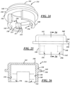
- FIG. 1 illustrates a baffle arm assembly 100 of a glassware forming machine that may be similar to that disclosed in U.S. Patent Application Publication 2008/0184742 , except for features of the present disclosure, which will be described in detail below.
- the assembly 100 includes a baffle holder manifold 101 suspended from ends of a baffle arm 102 and a link arm 103.
- the baffle arm 102 includes a collar 104 defining an aperture through which a segment 105 of the manifold 101 extends. The segment 105 is rotatable within the aperture of the collar 104 to allow rotation of the baffle manifold 101 with respect to the baffle arm 102.
- FIG. 2 illustrates a quick-connect/disconnect arrangement for mounting the baffle manifold 101 on the baffle arm 102.
- a threadless nut 210 is secured to the segment 105 to couple the manifold 101 to the baffle arm 102.
- the nut 210 may be coupled to the segment 105 via a bayonet connection.
- the collar 104 may also include a bushing, bearing, or the like (not shown) to facilitate rotation of the manifold segment 105 and the threadless nut 210 with respect to the collar 104. As shown in FIG.
- the segment 105 includes a threadless stud 106 to extend beyond an upper surface of the collar 104 and to be coupled to the threadless nut 210.
- directional words such as top, bottom, front, rear, behind, upper, lower, radial, circumferential, lateral, longitudinal, transverse, vertical, horizontal, and the like are employed by way of description and not necessarily limitation.
- the stud 106 includes two or more circumferentially spaced lugs 107.
- the lugs 107 may have end surfaces 108, side surfaces 109, and fillets 110 therebetween.
- the end surfaces 108 may be excurvate in shape and may define a major diameter of the stud 106.
- the side surfaces 109 also may be excurvate and may be axial extensions of a minor diameter 111 ( FIG. 6 ) of the stud 106.
- the fillets 110 may be incurvate and may define smooth transitions between the end and side surfaces 108, 109 of the stud 106.
- the stud 106 may be chamfered to promote good assembly of the nut 200.
- the stud 106 may be chamfered between a top surface 112 and the end surfaces 108 and fillets 110. Any other suitable configuration of the segment 105 and stud 106 may be used.
- the illustrative stud 106 includes two diametrically opposed lugs 107, a stud may include three or more circumferentially spaced apart lugs.
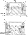
- the nut 210 generally includes a longitudinal axis A, a collar 212, and a cap or lock 214 carried by the collar 212 in any suitable manner.
- the lock 214 is coupled to the collar 212 in a rotationally fixed but axially movable manner.
- the nut 210 may be a generally cylindrical device, wherein the collar 212 and the lock 214 may be generally cylindrical components.
- the nut 210 also includes a spring 216 to bias the collar 212 and the lock 214 in a general direction away from one another, and a retainer 218 to retain the lock 214 to the collar 212.
- the spring 216 is disposed between the collar 212 and the lock 214, the lock 214 is compressed against the spring 216 and the collar 212, and the retainer 218 is coupled to the lock 214 while the lock 214 is compressed against the collar 212. Once the retainer 218 is coupled to the lock 214, compression on the lock 214 may be released.
- the nut 210 may be a self-contained assembly.
- the collar 212 includes an axially extending wall 220 extending axially between first and second ends 222, 224, and a stepped passage 226 surrounded by the wall 220.
- the passage 226 may be defined by a minor diameter 228, a first counterbore 230, and a second counterbore 232 ( FIG. 10 ) that define a radially extending wall 234.
- the collar 212 also includes lugs 236 projecting axially from the axially extending wall 220 at the first end 222.
- the lock 214 includes an axially extending wall 238 ( FIG. 13 ) extending between first and second ends 240, 242 ( FIGS. 8 and 13 ) and a radially extending lug flange 244 that extends radially outwardly from the wall 238 and including lug pockets 246.
- the lock 214 also includes a barrel outer diameter 248 ( FIG. 13 ) to cooperate with the minor diameter 228 of the collar 212, and a shoulder outer diameter 250 ( FIG. 13 ) to cooperate with the first counterbore 230 of the collar 212.
- the lock 214 further includes a retainer groove 252 ( FIGS. 8 and 13 ) in the wall 238 adjacent the second lock end 242.
- the lock 214 also carries translational retention lugs 254 ( FIG. 12 ) and rotational retention lugs 256, wherein the translational retention lugs 254 are disposed circumferentially between the rotational retention lugs 256.
- the lock 214 includes an inner surface 258 from which the lugs 254, 256 inwardly project.
- the lugs 254, 256 define stud lug seats 260 and semi-circumferential stud lug clearance passages 262 therebetween.
- the two stud lug seats 260 correspond to the two stud lugs 107 of the stud 106 of FIGS. 4-6 , but any suitable quantity of corresponding seats 260 and lugs 107 may be provided.
- the lock 214 is rotationally coupled to the collar 212 by the collar lugs 236, which axially extend into the lug pockets 246 of the lock 214 and are axially movable therein.
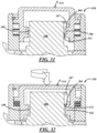
- the rotational retention lugs 256 are disposed in the radial fillets 110 of the stud 106 and cooperate with the radial end and side surfaces 108, 109 of the stud 106 to resist rotation of the nut 210 with respect to the stud 106.
- the spring 216 is disposed between the radially extending flange 244 of the lock 214 and the radially extending wall 234 of the collar 212 to bias the lock 214 and collar 212 in a general direction away from each other.
- the spring 216 also biases the threadless nut 210 with respect to the baffle manifold segment 105 to resist rotation of the threadless nut 210 with respect to the segment 105 absent compression of the spring 216.
- the spring 216 may be a wave spring.
- the spring 216 may be a C200-M1 wave spring available from Smalley Steel Ring Company of Lake Zurich, IL. Any other suitable type of spring may be used, including coil springs, elastomeric springs, or the like.
- the retainer 218 is disposed in the retainer groove 252 of the lock 214 such that the retainer 218 is disposed in the second counterbore 232 of the collar 212 and engages the radially extending wall 234 in a free state of the nut 210.
- the retainer 218 may be a snap ring.
- the retainer may be a M2400 external retaining ring available from Truarc Company LLC of Phillipsburg, NJ.
- the retainer 218 may be an integral portion of the lock 214, for example, a flange which may be upset, for example, after assembly of the collar 212, lock 214, and spring 216.
- the second end 224 of the collar 212 rests against a surface, for example, a surface of the baffle arm collar 104.
- the translational retention lugs 254 are disposed behind the stud lugs 107 to axially retain the nut 210 to the stud 106.
- the rotational locking lugs 256 are disposed adjacent the stud lugs 107 and axially overlap the side surfaces 109 of the stud lugs 107.
- the lock 214 When it is desired to decouple the nut 210 from the stud 106, the lock 214 is compressed toward the collar 212 against the bias force imposed by the spring 216. Eventually, as the lock 214 is displaced toward the collar 212, the rotational retention lugs 256 become rotatably movable with respect to the stud lugs 107 when the rotational retention lugs 256 have axially moved with respect to the stud lugs 107 so as to axially clear the stud lugs 107. For example, the top surfaces 264 of the rotational retention lugs 256 axially clear bottom surfaces 113 of the stud lugs 107 to permit the nut 210 to be rotated with respect to the stud 106.
- the stud lugs 107 may pass through the stud lug clearance passages 262 between the lugs 254, 256 so that the nut 210 may be removed from the stud 106.
- the nut 210 is placed over the stud 106 so that the stud lugs 107 pass through the stud lug clearance passages 262 between the lugs 254, 256, the nut 210 is advanced against the baffle arm collar 104 so that the lock 214 is compressed against the nut collar 212 such that the top surfaces 264 of the rotational retention lugs 256 axially clear the bottom surfaces 113 of the stud lugs 107 to permit the nut 210 to be rotated with respect to the stud 106.
- the translational retention lugs 254 are disposed behind the stud lugs 107 such that when the compression on the lock 214 is released, the spring 216 advances the lock 214 against the stud lugs 107 so as to seat the stud lugs 107 in the lug seats 260 axially against the translational retention lugs 254 and circumferentially against and between the rotational retention lugs 256.
- the collar 212 is an axially stationary and circumferentially rotatable member of the nut 210
- the lock 214 is a member of the nut 210 that is both axially translatable and circumferentially rotatable.
- FIGS. 17 through 30 illustrate another exemplary embodiment of the present disclosure. This embodiment is similar in many respects to the embodiment of FIGS. 7 through 16 and may be used within the exemplary environment of FIGS. 1 through 6 , and like numerals between the embodiments designate like or corresponding elements throughout the several views of the drawing figures. Accordingly, much of the common subject matter will generally not be repeated here and the embodiments are incorporated by reference into one another.
- a nut 310 generally includes a collar 312 and a lock 314 carried by the collar 312 in any suitable manner.
- the lock 314 is coupled to the collar 312 in a rotationally fixed but axially movable manner.
- the nut 310 may be a generally cylindrical device, wherein the collar 312 and the lock 314 may be generally cylindrical components.
- the nut 310 also includes a spring 316 to bias the collar 312 and the lock 314 in a general direction away from one another, and a retainer 318 to retain the lock 314 to the collar 312.
- the spring 316 is disposed between the collar 312 and the lock 314, the lock 314 is compressed against the spring 316 and the collar 312, and the retainer 318 is coupled to the collar 312 while the lock 314 is compressed. Once the retainer 318 is coupled to the collar 312, compression on the lock 314 may be released.
- the nut 310 may be a self-contained assembly.
- the collar 312 includes an axially extending wall 320 extending between first and second ends 322, 324, a stepped passage 326 surrounded by the wall 320 and defined by a radially extending wall 328 ( FIGS. 22-23 ) having inner surfaces 332 ( FIGS. 22-23 ) to cooperate with corresponding portions of the lock 314 ( FIG. 18 ), a counterbore 330 for the spring 316 ( FIG. 18 ), and a shoulder 334 therebetween.
- the collar 312 also includes a retainer groove 352 in the wall 320 adjacent the first end 322.
- the wall 320 may include alternating castellations and openings (not shown) circumferentially spaced in the first end 322 to assist with removal of the retainer 318.
- the collar 312 also includes translational retention lugs 354 extending radially inwardly from the radially extending wall 328.
- the lugs 354 project inwardly from the inner surfaces 332 and may be semi-circumferential or arcuate and may be stepped to include pilot portions 353 and lug engagement portions 355 that project axially beyond the shoulder 334.
- the lock 314 includes an axially extending wall 338 ( FIG. 26 ) extending between first and second ends 340, 342.
- the lock 314 further includes a radially extending flange 344 that extends radially outwardly from the axially extending wall 338 to cooperate with the spring 316 ( FIG. 18 ).
- the lock 314 also includes a barrel outer diameter 348 to cooperate with the minor diameter 328 of the collar 312 ( FIG. 18 ), and a flange outer diameter 350 to cooperate with the counterbore 330 of the collar 312 ( FIG. 18 ).
- the lock 314 additionally may include a radially extending wall 341 to assist with manual depression of the lock 314 toward the collar 312.
- the wall 314 may be omitted and/or a radially outwardly extending flange may be provided, for example, similar to that of the first exemplary embodiment.
- the lock 314 also carries rotational locking lugs 356, wherein the translational retention lugs 354 may be disposed circumferentially between the rotational retention lugs 356 in assembly.
- the lock 314 includes an inner surface 358 from which the lugs 356 inwardly project.
- the lugs 356 include sides 355 that may be disposed approximately 90 degrees with respect to one another, and a radiused nose 357 between the sides 355.
- the lugs 356 may be axially spaced from the second end 324 and/or from the flange 344.
- the lock 314 is rotationally coupled to the collar 312 by the translational retention lugs 354 of the collar 314 being disposed in the interruptions of the wall 338 of the lock 314 and between the rotational locking lugs 356 of the lock 314 and are axially movable with respect thereto.
- the lugs 354, 356 define stud lug seats 360 and stud lug clearance passages 362 therebetween.
- the rotational locking lugs 356 are disposed in the fillets 110 of the stud 106 and cooperate with the radial end and side surfaces 108, 109 of the stud 106 to resist rotation of the nut 310 with respect to the stud 106.
- the second end 324 of the collar 312 locates against the baffle arm collar 104.
- the spring 316 is disposed between the flange 344 of the lock 314 and the radially extending wall 320 of the collar 312 to bias the lock 314 and collar 312 in a general direction away from each other.
- the spring 316 also biases the threadless nut 310 with respect to the baffle manifold segment 105 to resist rotation of the threadless nut 310 with respect to the segment 105 absent compression of the spring 316.
- the spring 316 may be a wave spring.
- the spring may be a C200-L3-S17 wave spring available from Smalley Steel Ring Company of Lake Zurich, IL. Any other suitable springs may be used, including coil springs, elastomeric springs, or the like.
- the retainer 318 is disposed in the retainer groove 352 of the collar 312 such that the retainer 318 cooperates with the radially extending flange 344 of the lock 314 in assembly.
- the retainer 318 may be a snap ring.
- the retainer 318 may be a M2300 internal retaining ring available from Truarc Company LLC of Phillipsburg, NJ.
- the retainer 318 may be an integral portion of the collar 312, for example, a flange which may be upset, for example, after assembly of the collar 312, lock 314, and spring 316.
- the translational retaining lugs 354 are disposed behind the stud lugs 107 to axially retain the nut 310 to the stud 106. Also, the pilot portions 353 cooperate with a pilot diameter 114 of the segment 105. As shown in FIG. 31 , the rotational locking lugs 356 are disposed adjacent the stud lugs 107 and axially overlap the side surfaces 109 of the stud lugs 107.
- the nut 310 is placed over the stud 106 so that the stud lugs 107 pass between the lugs 354, 356, the nut 310 is advanced against the baffle arm collar 104 so that the lock 314 is compressed against the nut collar 312 such that the top surfaces 364 of the rotational locking lugs 356 axially clear bottom surfaces 113 of the lugs 107 to permit the nut 310 to be rotated with respect to the stud 106.
- the translational retaining lugs 356 are disposed behind the stud lugs 107.
- the collar 312 is an axially stationary and circumferentially rotatable member of the nut 310
- the lock 314 is a member of the nut 310 that is both axially translatable and circumferentially rotatable.
- FIGS. 15 and 30 A comparison of FIGS. 15 and 30 reveals a functional difference between the embodiments.
- the lock 214 when the segment 105 of the baffle manifold 101 moves in an axial direction, for example, due to sudden engagement or disengagement of the manifold 101 with another portion of a glassware forming machine, the lock 214 will also move relative the collar 212. This is because a space S is provided between the lock 214 and the segment 105 to allow axial disengagement and circumferential clearance of the radial retaining lugs (not shown) with respect to the stud lugs 107. Such "play" may be acceptable for many applications. However, in applications where such play is undesirable, the embodiment shown in FIG. 30 may be preferred.
- the collars 212, 312 and locks 214, 314 may be manufactured, for example, by machining from blanks, near net or investment casting, or powder metal fabrication.
- the collar 212 and lock 312 may be composed of, for example, AISI 4140 steel ion nitrided to a hardness of 58-62 on the Rockwell C scale.
- the collar 312 and lock 314 may be composed of, for example, AISI 8620 steel carburized to a hardness of 54-58 on the Rockwell C scale and to a depth of about 0.8 mm.
- the collars 212, 312 and locks 214, 314 may be manufactured in any other suitable manner and may be composed of any other suitable materials.
- the baffle arm assembly 100 presents just one exemplary environment of a myriad of possible environments for use with the threadless nuts 210, 310 of the present disclosure.
- Just a few examples include vehicle lug nuts, faucet spout nuts, or any application where tools and torque monitoring are not desired.
- the disclosure is intended to embrace all such modifications and variations as fall within the appended claims.
Landscapes
- Engineering & Computer Science (AREA)
- Chemical & Material Sciences (AREA)
- Organic Chemistry (AREA)
- Manufacturing & Machinery (AREA)
- Materials Engineering (AREA)
- General Engineering & Computer Science (AREA)
- Mechanical Engineering (AREA)
- Bolts, Nuts, And Washers (AREA)
- Connection Of Plates (AREA)
- Snaps, Bayonet Connections, Set Pins, And Snap Rings (AREA)
- Mutual Connection Of Rods And Tubes (AREA)
- Re-Forming, After-Treatment, Cutting And Transporting Of Glass Products (AREA)
- Hydraulic Turbines (AREA)
Applications Claiming Priority (3)
| Application Number | Priority Date | Filing Date | Title |
|---|---|---|---|
| US12/463,788 US8024944B2 (en) | 2009-05-11 | 2009-05-11 | Threadless nut |
| EP10716189.5A EP2429960B1 (en) | 2009-05-11 | 2010-04-21 | Glassware forming machine baffle arm assembly |
| PCT/US2010/031860 WO2010132183A1 (en) | 2009-05-11 | 2010-04-21 | Glassware forming machine baffle arm assembly |
Related Parent Applications (2)
| Application Number | Title | Priority Date | Filing Date |
|---|---|---|---|
| EP10716189.5A Division-Into EP2429960B1 (en) | 2009-05-11 | 2010-04-21 | Glassware forming machine baffle arm assembly |
| EP10716189.5A Division EP2429960B1 (en) | 2009-05-11 | 2010-04-21 | Glassware forming machine baffle arm assembly |
Publications (2)
| Publication Number | Publication Date |
|---|---|
| EP3590895A1 EP3590895A1 (en) | 2020-01-08 |
| EP3590895B1 true EP3590895B1 (en) | 2024-10-23 |
Family
ID=42470831
Family Applications (2)
| Application Number | Title | Priority Date | Filing Date |
|---|---|---|---|
| EP10716189.5A Active EP2429960B1 (en) | 2009-05-11 | 2010-04-21 | Glassware forming machine baffle arm assembly |
| EP19186677.1A Active EP3590895B1 (en) | 2009-05-11 | 2010-04-21 | Threadless nut |
Family Applications Before (1)
| Application Number | Title | Priority Date | Filing Date |
|---|---|---|---|
| EP10716189.5A Active EP2429960B1 (en) | 2009-05-11 | 2010-04-21 | Glassware forming machine baffle arm assembly |
Country Status (14)
| Country | Link |
|---|---|
| US (2) | US8024944B2 (pl) |
| EP (2) | EP2429960B1 (pl) |
| JP (1) | JP5592940B2 (pl) |
| CN (1) | CN102459104B (pl) |
| AR (1) | AR078042A1 (pl) |
| AU (1) | AU2010248037B2 (pl) |
| BR (1) | BRPI1014478B1 (pl) |
| CL (1) | CL2011002805A1 (pl) |
| ES (1) | ES2999654T3 (pl) |
| MX (1) | MX2011011906A (pl) |
| PL (1) | PL3590895T3 (pl) |
| TW (1) | TWI491576B (pl) |
| WO (1) | WO2010132183A1 (pl) |
| ZA (1) | ZA201108046B (pl) |
Families Citing this family (13)
| Publication number | Priority date | Publication date | Assignee | Title |
|---|---|---|---|---|
| US8024944B2 (en) | 2009-05-11 | 2011-09-27 | Owens-Brockway Glass Container Inc. | Threadless nut |
| PT2466159E (pt) * | 2010-12-15 | 2013-11-19 | Agustawestland Spa | Sistema de fixação |
| LV14316B (lv) * | 2011-02-11 | 2011-05-20 | Bruno Mellis | Detaļu slēgsavienojuma veidošanas ierīce, tā veidošanas paņēmiens un pielietojumi |
| US9243739B2 (en) * | 2012-05-30 | 2016-01-26 | Annex Products Pty. Ltd. | System and method for mounting a handheld electronic device |
| US9004871B2 (en) | 2012-08-17 | 2015-04-14 | General Electric Company | Stacked wheel assembly for a turbine system and method of assembling |
| US20140079511A1 (en) * | 2012-09-14 | 2014-03-20 | Worthington Maritime, LLC | Mounting Fastener for Securing Loads to Surfaces |
| US9279325B2 (en) | 2012-11-08 | 2016-03-08 | General Electric Company | Turbomachine wheel assembly having slotted flanges |
| US9701559B2 (en) * | 2013-05-14 | 2017-07-11 | Emhart Glass S.A. | Lock ring mounting arrangement for blow heads |
| DE102014200552B3 (de) * | 2014-01-15 | 2015-01-08 | Bayerische Motoren Werke Aktiengesellschaft | Klemmelement sowie Bauteilverbindung mit einem Klemmelement |
| US10135310B2 (en) * | 2017-01-11 | 2018-11-20 | Infinitum Electric Inc. | System and apparatus for modular axial field rotary energy device |
| DE102019131882A1 (de) * | 2018-11-27 | 2020-05-28 | North Kiteboarding Australasia | Zugdrachenverankerung und Verfahren zu deren Verwendung |
| US20220339796A1 (en) * | 2021-04-23 | 2022-10-27 | Bilsing Automation Gmbh | Mounting arrangement for multi-functional arm |
| US20230015919A1 (en) * | 2021-07-14 | 2023-01-19 | Brasscraft Manufacturing Company | Torque-limiting fastener and coupling |
Family Cites Families (39)
| Publication number | Priority date | Publication date | Assignee | Title |
|---|---|---|---|---|
| US3123880A (en) * | 1964-03-10 | Clip-on receptacle or socket member for one-quarter turn stud | ||
| US1843160A (en) | 1924-10-14 | 1932-02-02 | Hartford Empire Co | Glass blowing machine and method |
| US1832080A (en) * | 1928-10-18 | 1931-11-17 | Owens Illinois Glass Co | Machine for blowing hollow glass articles |
| US2442064A (en) * | 1943-10-28 | 1948-05-25 | Glenn L Martin Co | Fastener |
| US2364288A (en) * | 1943-11-17 | 1944-12-05 | Harold P Haggerty | Threadless nut and bolt |
| US2483660A (en) * | 1947-04-28 | 1949-10-04 | Harry J Morris | Attachment for mold carriers |
| US2900697A (en) * | 1955-04-05 | 1959-08-25 | Cuss John Freeman | Fasteners for panels and the like |
| US2839808A (en) * | 1956-02-15 | 1958-06-24 | Victor F Zahodiakin | Fastening devices |
| US3152822A (en) * | 1961-10-16 | 1964-10-13 | Camloc Fastener Corp | Push button fastener |
| US3281228A (en) | 1962-10-17 | 1966-10-25 | Chem Met Andersen Engineering | Cylinder for glass bottle making machine |
| US3171182A (en) * | 1963-05-13 | 1965-03-02 | Aloysius L Danehy | Fastener |
| US3472742A (en) * | 1966-03-15 | 1969-10-14 | Webb James E | Plating nickel on aluminum castings |
| US3564563A (en) * | 1968-01-09 | 1971-02-16 | Rex Chainbelt Inc | Adjustable quick acting fastener |
| US3554075A (en) * | 1968-11-07 | 1971-01-12 | Rex Chainbelt Inc | High strength adjustable quarter turn fastener |
| US4004905A (en) * | 1975-11-21 | 1977-01-25 | Owens-Illinois, Inc. | Safety lock for forming machine blowhead |
| US4308646A (en) * | 1979-05-02 | 1982-01-05 | Dzus Fastener Co., Inc. | Front insert receptacle |
| JPS5941522Y2 (ja) * | 1979-07-13 | 1984-11-30 | 住友電気工業株式会社 | 集光器接続機構 |
| US4339264A (en) * | 1980-08-18 | 1982-07-13 | Emhart Industries, Inc. | Glassware forming apparatus |
| EP0094150B1 (en) * | 1982-05-10 | 1986-06-11 | Dzus Fastener Europe Limited | Stud fastener receptacle |
| US4640478A (en) * | 1982-06-10 | 1987-02-03 | Automotive Products Plc | Quick connect cylinder mount structure |
| US4453964A (en) | 1982-07-12 | 1984-06-12 | Maul Technology Corporation | Air distributing mechanism for glass forming apparatus |
| JPH0623821B2 (ja) * | 1983-09-02 | 1994-03-30 | ミノルタカメラ株式会社 | バヨネットマウント装置とこの装置を用いる光学機器 |
| GB2166433B (en) * | 1984-10-27 | 1988-03-16 | Emhart Ind | Moving means for use in a glassware manufacturing machine |
| US4610713A (en) * | 1984-12-24 | 1986-09-09 | Clegg Wallace H | Settle blow head and baffle arm attachment for glassware molding machine |
| US4657462A (en) * | 1985-08-08 | 1987-04-14 | Simmons Fastener Corporation | Quarter-turn fastener |
| FR2589510B1 (fr) * | 1985-10-30 | 1987-12-18 | Neiman Sa | Verrou a montage baionnette |
| US4901987A (en) * | 1988-05-03 | 1990-02-20 | Smalley Steel Ring Company | Crest-to-crest compression spring with circular flat shim ends |
| US5290335A (en) * | 1990-01-22 | 1994-03-01 | Stewart William H | Plunger assembly for forming glass containers |
| US5545167A (en) * | 1995-04-11 | 1996-08-13 | Lin; Chih-I | Retaining mechanism of vertebral fixation rod |
| US5858050A (en) * | 1997-11-06 | 1999-01-12 | Emhart Glass S.A. | I.S. machine |
| JP3365751B2 (ja) | 1999-04-02 | 2003-01-14 | 京セラミタ株式会社 | 電磁クラッチ |
| US6292142B1 (en) | 1999-05-24 | 2001-09-18 | Raytheon Company | Locking assembly |
| JP3865538B2 (ja) | 1999-07-16 | 2007-01-10 | 自動車電機工業株式会社 | アクチュエータ |
| JP4154712B2 (ja) * | 2001-01-26 | 2008-09-24 | 株式会社山武 | 回転弁駆動用アクチュエータ及びこれを備えた弁装置 |
| US6530682B2 (en) | 2001-02-28 | 2003-03-11 | Wen-Chang Wu | Structure multi-cut type lamp pipe connector componentry |
| ATE329139T1 (de) * | 2002-08-16 | 2006-06-15 | Siemens Ag | Befestigungssystem |
| CN1859475B (zh) * | 2005-07-22 | 2010-05-12 | 华为技术有限公司 | 一种实现多媒体回铃音的方法及系统 |
| US8166779B2 (en) * | 2006-10-13 | 2012-05-01 | Owens-Brockway Glass Container Inc. | Baffle system for blank molds of a glassware forming machine |
| US8024944B2 (en) | 2009-05-11 | 2011-09-27 | Owens-Brockway Glass Container Inc. | Threadless nut |
-
2009
- 2009-05-11 US US12/463,788 patent/US8024944B2/en active Active
-
2010
- 2010-04-21 AU AU2010248037A patent/AU2010248037B2/en active Active
- 2010-04-21 EP EP10716189.5A patent/EP2429960B1/en active Active
- 2010-04-21 ES ES19186677T patent/ES2999654T3/es active Active
- 2010-04-21 CN CN201080032198.1A patent/CN102459104B/zh not_active Expired - Fee Related
- 2010-04-21 BR BRPI1014478-1A patent/BRPI1014478B1/pt active IP Right Grant
- 2010-04-21 EP EP19186677.1A patent/EP3590895B1/en active Active
- 2010-04-21 JP JP2012510819A patent/JP5592940B2/ja not_active Expired - Fee Related
- 2010-04-21 MX MX2011011906A patent/MX2011011906A/es active IP Right Grant
- 2010-04-21 PL PL19186677.1T patent/PL3590895T3/pl unknown
- 2010-04-21 WO PCT/US2010/031860 patent/WO2010132183A1/en not_active Ceased
- 2010-05-07 TW TW099114595A patent/TWI491576B/zh not_active IP Right Cessation
- 2010-05-10 AR ARP100101585A patent/AR078042A1/es active IP Right Grant
- 2010-10-12 US US12/902,469 patent/US8313274B2/en active Active
-
2011
- 2011-11-02 ZA ZA2011/08046A patent/ZA201108046B/en unknown
- 2011-11-10 CL CL2011002805A patent/CL2011002805A1/es unknown
Also Published As
| Publication number | Publication date |
|---|---|
| US20110027048A1 (en) | 2011-02-03 |
| CL2011002805A1 (es) | 2012-04-09 |
| US8024944B2 (en) | 2011-09-27 |
| CN102459104B (zh) | 2014-06-25 |
| US8313274B2 (en) | 2012-11-20 |
| TWI491576B (zh) | 2015-07-11 |
| JP5592940B2 (ja) | 2014-09-17 |
| WO2010132183A1 (en) | 2010-11-18 |
| EP2429960B1 (en) | 2019-08-28 |
| AR078042A1 (es) | 2011-10-12 |
| BRPI1014478B1 (pt) | 2019-10-08 |
| ES2999654T3 (en) | 2025-02-26 |
| JP2012526958A (ja) | 2012-11-01 |
| TW201102359A (en) | 2011-01-16 |
| AU2010248037B2 (en) | 2013-11-21 |
| BRPI1014478A2 (pt) | 2016-04-05 |
| AU2010248037A1 (en) | 2011-12-08 |
| ZA201108046B (en) | 2013-03-27 |
| CN102459104A (zh) | 2012-05-16 |
| PL3590895T3 (pl) | 2025-01-13 |
| EP3590895A1 (en) | 2020-01-08 |
| US20100284767A1 (en) | 2010-11-11 |
| MX2011011906A (es) | 2011-12-08 |
| EP2429960A1 (en) | 2012-03-21 |
Similar Documents
| Publication | Publication Date | Title |
|---|---|---|
| EP3590895B1 (en) | Threadless nut | |
| EP2427681B1 (en) | Side-locking clamping apparatus and method | |
| AU2021286248A1 (en) | A Swivelling Joint | |
| JP2007521146A5 (pl) | ||
| US8616107B2 (en) | Punching tool | |
| CN105073345A (zh) | 将承载有轴承罩和用于固定的螺钉的内轴承座圈安装至涡轮机中的工具、方法和工具套组 | |
| US20180339377A1 (en) | Concentric Actuation and Reaction Torque Transfer System | |
| GB2513740A (en) | Mechanical system for a turbine engine, turbine engine, and method for attaching a mechanical system within a turbine engine | |
| EP2228176B1 (en) | Antitheft locking device and method for its production | |
| CN111561521B (zh) | 一种法兰单元及防止螺栓卡涩的法兰结构 | |
| CN209938226U (zh) | 驱动轴支架及驱动轴总成 | |
| US11555520B2 (en) | Cover assembly for bearing | |
| US5586483A (en) | Piston and rod assembly | |
| CN222563586U (zh) | 转子和电机 | |
| EP2505381B1 (en) | A form-coupling arrangement in a bearing ring for a motor vehicle wheel | |
| CN113247762A (zh) | 一种吊具 | |
| EP1651894B1 (en) | Zero clearance c-ring asssembly | |
| CN217965135U (zh) | 一种齿轮夹紧装置 | |
| CN207223738U (zh) | 背衬轴承外圈修磨工装 | |
| CA2944803C (en) | Two-piece ceramic ferrule assembly | |
| CN208527783U (zh) | 一种换热管弯管装置 | |
| CN215153644U (zh) | 一种通航轻型飞机轮毂拆装的装置 | |
| US20250116301A1 (en) | Disc coupling | |
| EP0630349A1 (en) | FUT SECURITY. | |
| CN105042047A (zh) | 一种限位装置和减速器 |
Legal Events
| Date | Code | Title | Description |
|---|---|---|---|
| PUAI | Public reference made under article 153(3) epc to a published international application that has entered the european phase |
Free format text: ORIGINAL CODE: 0009012 |
|
| STAA | Information on the status of an ep patent application or granted ep patent |
Free format text: STATUS: THE APPLICATION HAS BEEN PUBLISHED |
|
| AC | Divisional application: reference to earlier application |
Ref document number: 2429960 Country of ref document: EP Kind code of ref document: P |
|
| AK | Designated contracting states |
Kind code of ref document: A1 Designated state(s): AT BE BG CH CY CZ DE DK EE ES FI FR GB GR HR HU IE IS IT LI LT LU LV MC MK MT NL NO PL PT RO SE SI SK SM TR |
|
| AX | Request for extension of the european patent |
Extension state: AL BA ME RS |
|
| STAA | Information on the status of an ep patent application or granted ep patent |
Free format text: STATUS: REQUEST FOR EXAMINATION WAS MADE |
|
| 17P | Request for examination filed |
Effective date: 20200630 |
|
| RBV | Designated contracting states (corrected) |
Designated state(s): AT BE BG CH CY CZ DE DK EE ES FI FR GB GR HR HU IE IS IT LI LT LU LV MC MK MT NL NO PL PT RO SE SI SK SM TR |
|
| STAA | Information on the status of an ep patent application or granted ep patent |
Free format text: STATUS: EXAMINATION IS IN PROGRESS |
|
| 17Q | First examination report despatched |
Effective date: 20231211 |
|
| GRAP | Despatch of communication of intention to grant a patent |
Free format text: ORIGINAL CODE: EPIDOSNIGR1 |
|
| STAA | Information on the status of an ep patent application or granted ep patent |
Free format text: STATUS: GRANT OF PATENT IS INTENDED |
|
| INTG | Intention to grant announced |
Effective date: 20240607 |
|
| GRAS | Grant fee paid |
Free format text: ORIGINAL CODE: EPIDOSNIGR3 |
|
| GRAA | (expected) grant |
Free format text: ORIGINAL CODE: 0009210 |
|
| STAA | Information on the status of an ep patent application or granted ep patent |
Free format text: STATUS: THE PATENT HAS BEEN GRANTED |
|
| P01 | Opt-out of the competence of the unified patent court (upc) registered |
Free format text: CASE NUMBER: APP_50418/2024 Effective date: 20240905 |
|
| AC | Divisional application: reference to earlier application |
Ref document number: 2429960 Country of ref document: EP Kind code of ref document: P |
|
| AK | Designated contracting states |
Kind code of ref document: B1 Designated state(s): AT BE BG CH CY CZ DE DK EE ES FI FR GB GR HR HU IE IS IT LI LT LU LV MC MK MT NL NO PL PT RO SE SI SK SM TR |
|
| REG | Reference to a national code |
Ref country code: GB Ref legal event code: FG4D |
|
| REG | Reference to a national code |
Ref country code: CH Ref legal event code: EP |
|
| REG | Reference to a national code |
Ref country code: DE Ref legal event code: R096 Ref document number: 602010069549 Country of ref document: DE |
|
| REG | Reference to a national code |
Ref country code: IE Ref legal event code: FG4D |
|
| REG | Reference to a national code |
Ref country code: LT Ref legal event code: MG9D |
|
| REG | Reference to a national code |
Ref country code: NL Ref legal event code: MP Effective date: 20241023 Ref country code: ES Ref legal event code: FG2A Ref document number: 2999654 Country of ref document: ES Kind code of ref document: T3 Effective date: 20250226 |
|
| REG | Reference to a national code |
Ref country code: AT Ref legal event code: MK05 Ref document number: 1734727 Country of ref document: AT Kind code of ref document: T Effective date: 20241023 |
|
| PG25 | Lapsed in a contracting state [announced via postgrant information from national office to epo] |
Ref country code: NL Free format text: LAPSE BECAUSE OF FAILURE TO SUBMIT A TRANSLATION OF THE DESCRIPTION OR TO PAY THE FEE WITHIN THE PRESCRIBED TIME-LIMIT Effective date: 20241023 |
|
| PG25 | Lapsed in a contracting state [announced via postgrant information from national office to epo] |
Ref country code: NL Free format text: LAPSE BECAUSE OF FAILURE TO SUBMIT A TRANSLATION OF THE DESCRIPTION OR TO PAY THE FEE WITHIN THE PRESCRIBED TIME-LIMIT Effective date: 20241023 |
|
| PG25 | Lapsed in a contracting state [announced via postgrant information from national office to epo] |
Ref country code: HR Free format text: LAPSE BECAUSE OF FAILURE TO SUBMIT A TRANSLATION OF THE DESCRIPTION OR TO PAY THE FEE WITHIN THE PRESCRIBED TIME-LIMIT Effective date: 20241023 Ref country code: IS Free format text: LAPSE BECAUSE OF FAILURE TO SUBMIT A TRANSLATION OF THE DESCRIPTION OR TO PAY THE FEE WITHIN THE PRESCRIBED TIME-LIMIT Effective date: 20250223 Ref country code: PT Free format text: LAPSE BECAUSE OF FAILURE TO SUBMIT A TRANSLATION OF THE DESCRIPTION OR TO PAY THE FEE WITHIN THE PRESCRIBED TIME-LIMIT Effective date: 20250224 |
|
| PG25 | Lapsed in a contracting state [announced via postgrant information from national office to epo] |
Ref country code: FI Free format text: LAPSE BECAUSE OF FAILURE TO SUBMIT A TRANSLATION OF THE DESCRIPTION OR TO PAY THE FEE WITHIN THE PRESCRIBED TIME-LIMIT Effective date: 20241023 |
|
| PG25 | Lapsed in a contracting state [announced via postgrant information from national office to epo] |
Ref country code: BG Free format text: LAPSE BECAUSE OF FAILURE TO SUBMIT A TRANSLATION OF THE DESCRIPTION OR TO PAY THE FEE WITHIN THE PRESCRIBED TIME-LIMIT Effective date: 20241023 |
|
| PG25 | Lapsed in a contracting state [announced via postgrant information from national office to epo] |
Ref country code: NO Free format text: LAPSE BECAUSE OF FAILURE TO SUBMIT A TRANSLATION OF THE DESCRIPTION OR TO PAY THE FEE WITHIN THE PRESCRIBED TIME-LIMIT Effective date: 20250123 |
|
| PG25 | Lapsed in a contracting state [announced via postgrant information from national office to epo] |
Ref country code: LV Free format text: LAPSE BECAUSE OF FAILURE TO SUBMIT A TRANSLATION OF THE DESCRIPTION OR TO PAY THE FEE WITHIN THE PRESCRIBED TIME-LIMIT Effective date: 20241023 Ref country code: AT Free format text: LAPSE BECAUSE OF FAILURE TO SUBMIT A TRANSLATION OF THE DESCRIPTION OR TO PAY THE FEE WITHIN THE PRESCRIBED TIME-LIMIT Effective date: 20241023 Ref country code: GR Free format text: LAPSE BECAUSE OF FAILURE TO SUBMIT A TRANSLATION OF THE DESCRIPTION OR TO PAY THE FEE WITHIN THE PRESCRIBED TIME-LIMIT Effective date: 20250124 |
|
| PG25 | Lapsed in a contracting state [announced via postgrant information from national office to epo] |
Ref country code: SM Free format text: LAPSE BECAUSE OF FAILURE TO SUBMIT A TRANSLATION OF THE DESCRIPTION OR TO PAY THE FEE WITHIN THE PRESCRIBED TIME-LIMIT Effective date: 20241023 |
|
| PGFP | Annual fee paid to national office [announced via postgrant information from national office to epo] |
Ref country code: PL Payment date: 20250405 Year of fee payment: 16 Ref country code: DE Payment date: 20250429 Year of fee payment: 16 |
|
| PG25 | Lapsed in a contracting state [announced via postgrant information from national office to epo] |
Ref country code: DK Free format text: LAPSE BECAUSE OF FAILURE TO SUBMIT A TRANSLATION OF THE DESCRIPTION OR TO PAY THE FEE WITHIN THE PRESCRIBED TIME-LIMIT Effective date: 20241023 |
|
| PGFP | Annual fee paid to national office [announced via postgrant information from national office to epo] |
Ref country code: GB Payment date: 20250428 Year of fee payment: 16 Ref country code: ES Payment date: 20250505 Year of fee payment: 16 |
|
| PGFP | Annual fee paid to national office [announced via postgrant information from national office to epo] |
Ref country code: IT Payment date: 20250422 Year of fee payment: 16 |
|
| PG25 | Lapsed in a contracting state [announced via postgrant information from national office to epo] |
Ref country code: EE Free format text: LAPSE BECAUSE OF FAILURE TO SUBMIT A TRANSLATION OF THE DESCRIPTION OR TO PAY THE FEE WITHIN THE PRESCRIBED TIME-LIMIT Effective date: 20241023 |
|
| PG25 | Lapsed in a contracting state [announced via postgrant information from national office to epo] |
Ref country code: RO Free format text: LAPSE BECAUSE OF FAILURE TO SUBMIT A TRANSLATION OF THE DESCRIPTION OR TO PAY THE FEE WITHIN THE PRESCRIBED TIME-LIMIT Effective date: 20241023 |
|
| REG | Reference to a national code |
Ref country code: DE Ref legal event code: R097 Ref document number: 602010069549 Country of ref document: DE |
|
| PG25 | Lapsed in a contracting state [announced via postgrant information from national office to epo] |
Ref country code: SK Free format text: LAPSE BECAUSE OF FAILURE TO SUBMIT A TRANSLATION OF THE DESCRIPTION OR TO PAY THE FEE WITHIN THE PRESCRIBED TIME-LIMIT Effective date: 20241023 |
|
| PGFP | Annual fee paid to national office [announced via postgrant information from national office to epo] |
Ref country code: CZ Payment date: 20250407 Year of fee payment: 16 |
|
| PLBE | No opposition filed within time limit |
Free format text: ORIGINAL CODE: 0009261 |
|
| STAA | Information on the status of an ep patent application or granted ep patent |
Free format text: STATUS: NO OPPOSITION FILED WITHIN TIME LIMIT |
|
| PG25 | Lapsed in a contracting state [announced via postgrant information from national office to epo] |
Ref country code: SE Free format text: LAPSE BECAUSE OF FAILURE TO SUBMIT A TRANSLATION OF THE DESCRIPTION OR TO PAY THE FEE WITHIN THE PRESCRIBED TIME-LIMIT Effective date: 20241023 |
|
| 26N | No opposition filed |
Effective date: 20250724 |
|
| REG | Reference to a national code |
Ref country code: CH Ref legal event code: H13 Free format text: ST27 STATUS EVENT CODE: U-0-0-H10-H13 (AS PROVIDED BY THE NATIONAL OFFICE) Effective date: 20251125 |
|
| PG25 | Lapsed in a contracting state [announced via postgrant information from national office to epo] |
Ref country code: LU Free format text: LAPSE BECAUSE OF NON-PAYMENT OF DUE FEES Effective date: 20250421 |