EP3590760A1 - Kopfstütze - Google Patents
Kopfstütze Download PDFInfo
- Publication number
- EP3590760A1 EP3590760A1 EP19020413.1A EP19020413A EP3590760A1 EP 3590760 A1 EP3590760 A1 EP 3590760A1 EP 19020413 A EP19020413 A EP 19020413A EP 3590760 A1 EP3590760 A1 EP 3590760A1
- Authority
- EP
- European Patent Office
- Prior art keywords
- headrest
- locking means
- holding device
- link
- locking
- Prior art date
- Legal status (The legal status is an assumption and is not a legal conclusion. Google has not performed a legal analysis and makes no representation as to the accuracy of the status listed.)
- Granted
Links
Images








Classifications
-
- B—PERFORMING OPERATIONS; TRANSPORTING
- B60—VEHICLES IN GENERAL
- B60N—SEATS SPECIALLY ADAPTED FOR VEHICLES; VEHICLE PASSENGER ACCOMMODATION NOT OTHERWISE PROVIDED FOR
- B60N2/00—Seats specially adapted for vehicles; Arrangement or mounting of seats in vehicles
- B60N2/80—Head-rests
- B60N2/806—Head-rests movable or adjustable
- B60N2/838—Tiltable
- B60N2/862—Tiltable with means for maintaining a desired position when the seat-back is adjusted, e.g. parallelogram mechanisms
-
- B—PERFORMING OPERATIONS; TRANSPORTING
- B60—VEHICLES IN GENERAL
- B60N—SEATS SPECIALLY ADAPTED FOR VEHICLES; VEHICLE PASSENGER ACCOMMODATION NOT OTHERWISE PROVIDED FOR
- B60N2/00—Seats specially adapted for vehicles; Arrangement or mounting of seats in vehicles
- B60N2/80—Head-rests
- B60N2/806—Head-rests movable or adjustable
- B60N2/838—Tiltable
- B60N2/841—Tiltable characterised by their locking devices
- B60N2/847—Tiltable characterised by their locking devices with stepwise positioning
-
- B—PERFORMING OPERATIONS; TRANSPORTING
- B60—VEHICLES IN GENERAL
- B60N—SEATS SPECIALLY ADAPTED FOR VEHICLES; VEHICLE PASSENGER ACCOMMODATION NOT OTHERWISE PROVIDED FOR
- B60N2/00—Seats specially adapted for vehicles; Arrangement or mounting of seats in vehicles
- B60N2/80—Head-rests
- B60N2/806—Head-rests movable or adjustable
- B60N2/838—Tiltable
- B60N2/853—Tiltable characterised by their adjusting mechanisms, e.g. electric motors
-
- B—PERFORMING OPERATIONS; TRANSPORTING
- B60—VEHICLES IN GENERAL
- B60N—SEATS SPECIALLY ADAPTED FOR VEHICLES; VEHICLE PASSENGER ACCOMMODATION NOT OTHERWISE PROVIDED FOR
- B60N2/00—Seats specially adapted for vehicles; Arrangement or mounting of seats in vehicles
- B60N2/80—Head-rests
- B60N2/806—Head-rests movable or adjustable
- B60N2/838—Tiltable
- B60N2/841—Tiltable characterised by their locking devices
-
- B—PERFORMING OPERATIONS; TRANSPORTING
- B60—VEHICLES IN GENERAL
- B60N—SEATS SPECIALLY ADAPTED FOR VEHICLES; VEHICLE PASSENGER ACCOMMODATION NOT OTHERWISE PROVIDED FOR
- B60N2/00—Seats specially adapted for vehicles; Arrangement or mounting of seats in vehicles
- B60N2/80—Head-rests
- B60N2/806—Head-rests movable or adjustable
- B60N2/865—Head-rests movable or adjustable providing a fore-and-aft movement with respect to the occupant's head
Definitions
- Such a headrest is from the DE 10 2010 007 942 A1 known.
- the headrest comprises a holding plate which is attached to the backrest of a vehicle seat.
- Two parallel upper and lower struts are articulated to the holding plate, which are articulatedly connected to a head part.
- the headrest part can thus be moved between a rear and a front position.
- the upper struts are provided with a toothing which can be releasably engaged with a pivotable latch in order to lock the headrest part in the set position.
- the headrest according to the invention comprises a headrest part which can be mounted on a structure of a vehicle by means of a holding device.
- the term holding device denotes all devices which are suitable for fastening to the structure.
- all parts which are indirectly connected to the structure are likewise the structure of the vehicle, for example vehicle seat, vehicle console, wall or floor of the vehicle.
- the headrest part can be moved relative to the holding device by means of an adjusting device forwards to the head of a user and in the opposite direction.
- the movement does not have to be a straight-line movement in the X-plane, the movement can only have parts of such a movement.
- the adjusting device comprises at least a first link and a second link, each link forming at least one joint with the headrest part and with the holding device.
- the wording "forms a joint with the headrest part" in the sense of the invention is to be understood in such a way that the joint can also be formed with a part which is connected to the headrest part, such as e.g. a support part on which the headrest part is held immovably or movably.
- At least two handlebars are arranged one behind the other in the x direction.
- the adjusting device comprises a locking device with which a relative movement between the holding device and the head part can be detachably blocked.
- the locking device is movable between a locking position, in which a relative movement between the holding device and the headrest part is blocked in at least one direction, and a release position, in which the relative movement is possible.
- the locking device comprises first locking means which are held on at least one handlebar and second locking means which are assigned to the headrest part or the holding device, the locking means being releasably engageable.
- the locking means need not be attached directly to the handlebar or the headrest part. They can also be arranged on parts which are connected to the headrest part or to the handlebar.
- the first locking means are in the locking position and the second locking means in engagement, in the release position the locking means are disengaged.
- the first locking means have e.g. Positive locking means, in particular in the form of a toothing, and the second locking means have complementary positive locking means. Due to the cooperating positive locking means, a relative movement between the headrest part and the handlebar or between the holding device and the handlebar is prevented. With the form-locking means, a functionally reliable movement of the locking device between the locking position and the release position as well as a secure locking is made possible.
- the first locking means are e.g. formed on an end portion of the handlebar.
- the end region of the handlebar can face the holding device or alternatively can face away from the holding device, i.e. be facing the head part. If the relative movement of the headrest part and at least one link is blocked, the first locking means are e.g. facing away from the holding device. In this case, there is no need to overcome a large distance between the end region of the handlebar and the headrest part.
- the first locking means and / or the second locking means are e.g. trained on a circular path.
- the second locking means are assigned, for example, to at least one movable bolt which is movably held on the head contact part or on the holding device between the bolt position and the release position.
- the trajectory of the bolt is, for example, different from the trajectory of the head part.
- the trajectory of the bolt is aligned, for example, transversely to the trajectory of the head part. During the movement of the headrest part takes place in the x direction, for example the movement of the bolt in the y direction can take place.
- the first handlebar and the second handlebar have e.g. arms arranged parallel to each other. A distance is formed between the parallel arms.
- Each handlebar has e.g. two arms that are movable in parallel planes, the planes extending in the x direction.
- the parallel arms are connected to one another by means of a traverse. This provides greater stability through stiffening.
- the parallel arms can alternatively only be motion-connected by the part with which they form a joint, i.e. with the holding device or the head part.
- Each arm forms e.g. one joint with the head part and one joint with the holding device.
- FIGS 1 to 6 designated by the reference numeral 10.
- the headrest comprises a holding device 11, which in the present exemplary embodiment has support rods 12a and 12b. Instead of the support rods 12a and 12b, the holding device could alternatively also have a support rod bracket.
- the holding device 11 can be fastened to the structure of a backrest in a conventional manner.
- the headrest 10 comprises a head contact part 13 with a head contact surface 32, which is mounted on the holding device 11 with an adjusting device 14 in such a way that it is between one of the two and the other 1 to 4 shown front position and one in Fig. 6a shown rear position is movable.
- the headrest part can be locked in different positions.
- the adjusting device 14 comprises a first link 16 and a second link 17 one behind the other in the x direction.
- the handlebar 16 is constructed in a U-shape and comprises arms 18a and 18b and a traverse 19 connecting the arms 18a and 18b.
- the handlebar 17 is U-shaped. It comprises arms 20a and 20b and a crossbeam 21 which connects the arms 20a and 20b.
- the arms 18a and 18b and the arms 20a and 20b could not be connected to one another by means of a traverse. With the trusses 19 and 21, however, greater stability is achieved.
- the first link 16 forms a joint G with the support rods 12a and 12b, so that the first link 16 is pivotable about a pivot axis a1 relative to the support rods 12a and 12b.
- each arm 18a and 18b forms a joint G with a supporting part 22, on which the head contact part 13 is held in an adjustable manner is. In this way, the support member 22 is pivotable about a pivot axis a2 relative to the first link 16.
- the second link 17 forms joints G with the support rods 12a and 12b at a lower end region, which is formed by the crossmember 21, so that a pivot axis a3 is formed.
- each arm 20a and 20b forms a joint G with the support part 22, the joints G defining a pivot axis a4.
- the fixedly arranged support rods 12a and 12b, the links 16 and 17 and the support part 22 thus form a coupling gear.
- the headrest part 13 is thus movably mounted on the holding device 11 along a coupling curve, with a movement in the directions x1 or x2 and a movement in the directions z1 or z2.
- the arm 18a of the first link 16 has locking means 24a and the arm 18b locking means 24b (see FIGS Fig. 4 and 5 ). These are designed in the form of a toothing that extends along a circular path around the pivot axis a2.
- the tip circle of the circular path of the locking means 24a is in the 6c and 6d designated 37.
- the arm 20a of the second link 17 has locking means 25a at an upper end region and the arm 20b locking means 25b, which have the shape of a toothing which extends along a circular path about the pivot axis a4.
- the tip circle of the circular path of the locking means 25a is in the 6c and 6d designated 38.
- a latch 28a and a latch 28b can be moved in a receiving space 26 of the supporting part 22 (the latch 28b is shown in FIG Fig. 5 only indicated by a dashed line).
- the bolt 28a has locking means 35a and 36a which are connected to the locking means 24a and 25a work together.
- the latch 28b has locking means 35b and 36b which cooperate with the locking means 24b and 25b. In this way, the latch 28a can be releasably moved into engagement with the locking means 24a and 25a of the links 16 and 17. In the same way, the latch 28b can be moved releasably into engagement with the locking means 24b and 25b.
- the links 16 and 17 can be engaged do not rotate about the axes a2 and a4 relative to the support part 22, ie that movement of the headrest part 13 is blocked in at least one direction.
- the locking means of the bolts 27 and 28 are out of engagement with the locking means of the links 16 and 17, i.e. the adjustment device 14 is freely movable and the headrest part 13 can be moved in the directions x1 and x2 between the front and the rear position.
- the release position is not shown in the figures.
- a switch can be provided on the headrest part 13, on the support part 22 or at any other point, the movement of the switch being transmitted to a movement of the bolts 27 and 28 by means of a transmission device.
- the movement of the bolts 27 and 28 takes place in the present exemplary embodiment via a lever 29 (see Fig. 5 ), which is part of such a transmission device.
- the lever 29 is mounted on the supporting part 22 so as to be pivotable about a pivot axis a5.
- the lever 29 has arms 30 and 31, the arm 30 being in contact with the bolt 28a and the arm 31 in contact with the bolt 28b. Pivots the lever 29 in the direction u1 clockwise Fig. 6 , the latch 28b in the direction y1 and the latch 28a in the direction y2 are moved into the release position.
- the bolts 27 and 28 are spring-loaded in such a way that when moving into the release position, spring energy is built up, which loads the bolts 28a and 28b back into the bolt position. When the lever 29 is relieved, the bolts 28a and 28b are therefore automatically moved into the bolt position according to Fig. 5 moved back.
- the head contact part 13 is guided in a height-adjustable manner on the support part 22 in the directions z1 and z2 and can be locked in different height positions with a locking device 23.
- the locking device 23 comprises locking means 33 assigned to the head contact part 13 and locking means 34 assigned to the support part 22.
- the adjusting device 14 has a first link 40 and a second link 41, which differ from the links 16 and 17 in that the links 40 and 41 are made of plastic.
- the first link 40 is larger and provided with ribs 42 which serve for stabilization.
- the second embodiment differs from the first embodiment in that only the first link 40 locking means 43a and 43b is provided in the form of a toothing.
- the handlebars 40 and 41 also have a U-shaped shape despite their different shape.
- the link 40 is formed with arms 44a and 44b and a crossbar 45 connecting the arms 44a and 44b.
- the link 41 has arms 46a and 46b and one connecting the arms 46a and 46b Traverse 47 on.
- the support rods 12a and 12b are connected to one another by means of a connecting part 51.
- the locking means 43a are arranged on an upper end region of the arm 44a facing away from the holding device 11 and the locking means 43b are arranged on an upper end region of the arm 44b of the handlebar 40.
- the locking device 15 has two latches 48a and 48b, which are arranged in the receiving space 26 and can be moved in the directions y1 and y2. In the locking position, locking means 49a of the locking bar 48a engage the locking means 43a and locking means 49b of the locking bar 48b engage the locking means 43b.
- the second exemplary embodiment is essentially the same as the first exemplary embodiment.
Landscapes
- Engineering & Computer Science (AREA)
- Aviation & Aerospace Engineering (AREA)
- Transportation (AREA)
- Mechanical Engineering (AREA)
- Chair Legs, Seat Parts, And Backrests (AREA)
- Seats For Vehicles (AREA)
- Chairs For Special Purposes, Such As Reclining Chairs (AREA)
Abstract
Description
- Die Aufgabe wurde gelöst durch eine Kopfstütze mit den Merkmalen des Anspruchs 1.
- Eine solche Kopfstütze ist aus der
DE 10 2010 007 942 A1 bekannt. Die Kopfstütze umfasst ein Halteblech, welches an der Rückenlehne eines Fahrzeugsitzes befestigt ist. An dem Halteblech sind zwei parallel angeordnete obere und untere Streben angelenkt, die gelenkig mit einem Kopfanlageteil verbunden sind. Das Kopfanlageteil kann auf diese Weise zwischen einer hinteren und einer vorderen Position bewegt werden. Die oberen Streben sind mit einer Verzahnung versehen, die mit einem schwenkbaren Riegel lösbar in Eingriff gebracht werden können, um das Kopfanlageteil in der eingestellten Position zu verriegeln. - Es war Aufgabe der Erfindung, eine Kopfstütze zu schaffen, die in der Seitenansicht schmal gebaut ist. Außerdem war es Aufgabe der Erfindung, die Kopfstütze mit einer funktionssicheren Verriegelungsvorrichtung auszustatten, mit welcher das Kopfanlageteil in der eingestellten Position sicher verriegelbar ist.
- Die erfindungsgemäße Kopfstütze umfasst ein Kopfanlageteil, welches mittels einer Haltevorrichtung an einer Struktur eines Fahrzeugs, lagerbar ist. Der Begriff Haltevorrichtung bezeichnet im Sinne der Erfindung alle Vorrichtungen, die zur Befestigung an der Struktur geeignet sind. Alle Teile, die mittelbar mit der Struktur in Verbindung stehen, sind im Sinne der Erfindung ebenfalls Struktur des Fahrzeugs, z.B. Fahrzeugsitz, Fahrzeugkonsole, Wand oder Boden des Fahrzeugs.
- Das Kopfanlageteil ist relativ zu der Haltevorrichtung mittels einer Verstellvorrichtung nach vorne zu dem Kopf eines Benutzers und in entgegengesetzte Richtung zurück bewegbar. Die Bewegung muss dabei keine geradlinige Bewegung in der X-Ebene sein, die Bewegung kann lediglich Anteile einer solchen Bewegung aufweisen.
- Die Verstellvorrichtung umfasst wenigstens einen ersten Lenker und einen zweiten Lenker, wobei jeder Lenker mit dem Kopfanlageteil und mit der Haltevorrichtung wenigstens ein Gelenk bildet. Die Formulierung "mit dem Kopfanlageteil ein Gelenk bildet" ist im Sinne der Erfindung derart aufzufassen, dass das Gelenk auch mit einem Teil gebildet sein kann, welches mit dem Kopfanlageteil verbunden ist, wie z.B. einem Tragteil an welchem das Kopfanlageteil unbewegbar oder bewegbar gehalten ist. Wenigstens zwei Lenker sind in x-Richtung hintereinander angeordnet.
- Die Verstellvorrichtung umfasst eine Verriegelungsvorrichtung mit welcher eine Relativbewegung zwischen der Haltevorrichtung und dem Kopfanlageteil lösbar blockiert werden kann. Die Verriegelungsvorrichtung ist zwischen einer Riegelposition, in welcher eine Relativbewegung zwischen der Haltevorrichtung und dem Kopfanlageteil in wenigstens eine Richtung blockiert ist, und einer Löseposition, in welcher die Relativbewegung möglich ist, bewegbar.
- Die Verriegelungsvorrichtung umfasst erste Verriegelungsmittel, die an wenigstens einem Lenker gehalten sind und zweite Verriegelungsmittel, die dem Kopfanlageteil oder der Haltevorrichtung zugeordnet sind, wobei die Verriegelungsmittel lösbar in Eingriff bringbar sind. Die Verriegelungsmittel müssen nicht unmittelbar an dem Lenker oder dem Kopfanlageteil befestigt sein. Sie können auch an Teilen angeordnet sein, die mit dem Kopfanlageteil bzw. mit dem Lenker verbunden sind. In der Riegelposition sind die ersten Verriegelungsmittel und die zweiten Verriegelungsmittel in Eingriff, in der Löseposition sind die Verriegelungsmittel außer Eingriff.
- Die ersten Verriegelungsmittel weisen z.B. Formschlussmittel, insbesondere in Form einer Verzahnung auf und die zweiten Verriegelungsmittel weisen komplementäre Formschlussmittel auf. Aufgrund der zusammenwirkenden Formschlussmittel wird eine Relativbewegung zwischen dem Kopfanlageteil und dem Lenker oder zwischen der Haltevorrichtung und dem Lenker verhindert. Mit den Formschlussmitteln wird ein funktionssicheres Bewegen der Verriegelungsvorrichtung zwischen der Riegelposition und der Löseposition sowie eine sichere Verriegelung ermöglicht.
- Die ersten Verriegelungsmittel sind z.B. an einem Endbereich des Lenkers ausgebildet. Der Endbereich des Lenkers kann der Haltevorrichtung zugewandt sein oder alternativ von der Haltevorrichtung abgewandt, d.h. dem Kopfanlageteil zugewandt sein. Bei einer Blockierung der Relativbewegung von dem Kopfanlageteil und wenigstens einem Lenker sind die ersten Verriegelungsmittel z.B. der Haltevorrichtung abgewandt. In diesem Fall muss kein großer Abstand zwischen dem Endbereich des Lenkers und dem Kopfanlageteil überwunden werden. Die ersten Verriegelungsmittel und/oder die zweiten Verriegelungsmittel sind z.B. auf einer Kreisbahn ausgebildet.
- Die zweiten Verriegelungsmittel sind z.B. wenigstens einem bewegbaren Riegel zugeordnet, welcher zwischen der Riegelposition und der Löseposition bewegbar an dem Kopfanlageteil oder an der Haltevorrichtung gehalten ist. Die Bewegungsbahn des Riegels ist z.B. unterschiedlich zu der Bewegungsbahn des Kopfanlageteils. Die Bewegungsbahn des Riegels ist z.B. quer zu der Bewegungsbahn des Kopfanlageteils ausgerichtet. Während die Bewegung des Kopfanlageteils in x-Richtung stattfindet, kann z.B. die Bewegung des Riegels in y-Richtung stattfinden.
- Der erste Lenker und der zweite Lenker weisen z.B. parallel zueinander angeordnete Arme auf. Zwischen den parallelen Armen ist ein Abstand gebildet. Jeder Lenker weist z.B. zwei Arme auf, die in parallelen Ebenen bewegbar sind, wobei sich die Ebenen sich in x-Richtung erstrecken.
- Die parallelen Arme sind gemäß einer Ausführungsform mittels einer Traverse miteinander verbunden. Es wird damit eine größere Stabilität durch Versteifung erreicht. Die parallelen Arme können alternativ auch lediglich durch das Teil bewegungsverbunden sein, mit welchem sie ein Gelenk bilden, d.h. mit der Haltevorrichtung oder dem Kopfanlageteil.
- Jeder Arm bildet z.B. ein Gelenk mit dem Kopfanlageteil und ein Gelenk mit der Haltevorrichtung.
- Zwei Ausführungsbeispiele der Erfindung sind in der nachfolgenden Figurenbeschreibung, auch unter Bezugnahme auf die schematischen Zeichnungen, beispielhaft beschrieben. Dabei werden der Übersichtlichkeit halber - auch soweit unterschiedliche Ausführungsbespiele betroffen sind - gleiche oder vergleichbare Teile oder Elemente oder Bereiche mit gleichen Bezugszeichen, teilweise unter Hinzufügung kleiner Buchstaben, bezeichnet.
- Merkmale, die nur in Bezug auf ein Ausführungsbeispiel beschrieben, dargestellt oder offenbart sind, können im Rahmen der Erfindung auch bei jedem anderen Ausführungsbeispiel der Erfindung vorgesehen werden. Derartig geänderte Ausführungsbeispiele sind - auch wenn sie in den Zeichnungen nicht dargestellt sind - von der Erfindung mit umfasst.
- Alle offenbarten Merkmale sind für sich erfindungswesentlich. In die Offenbarung der Anmeldung wird hiermit auch der Offenbarungsinhalt der zitierten Druckschriften und der beschriebenen Vorrichtungen des Standes der Technik inhaltlich vollumfänglich mit einbezogen, auch zu dem Zweck, einzelne oder mehrere Merkmale der dort offenbarten Gegenstände in einen oder in mehrere Ansprüche der vorliegenden Anmeldung mit aufzunehmen. Auch solche geänderten Ausführungsbeispiele sind - auch wenn sie in den Zeichnungen nicht dargestellt sind - von der Erfindung mit umfasst.
- Es zeigen:
-
Fig. 1 eine perspektivische Ansicht eines ersten Ausführungsbeispiels der erfindungsgemäßen Kopfstütze schräg von vorne, wobei das Kopfanlageteil in einer vorderen Position angeordnet ist, -
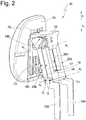
Fig. 2 eine perspektivische Ansicht der Kopfstütze gemäßFig. 1 von schräg hinten, -
Fig. 3 eine rückwärtige Ansicht der Kopfstütze, -
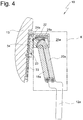
Fig. 4 eine Schnittansicht der Kopfstütze gemäß Schnittlinie A - A inFig. 3 , -
Fig. 5 eine Schnittansicht gemäß Schnittlinie B - B inFig. 3 , -
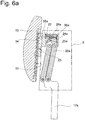
Fig. 6a eine Schnittansicht in Anlehnung anFig. 4 , wobei das Kopfanlageteil in einer hinteren Position angeordnet ist, -
Fig. 6b eine Ausschnittdarstellung gemäß Ausschnittlinie E inFig. 4 , wobei Bereiche des Tragteils der Übersichtigkeit halber nicht dargestellt sind, -
Fig. 6c eine Ausschnittdarstellung gemäß Ausschnittlinie F inFig. 6a , wobei Bereiche des Tragteils der Übersichtigkeit halber nicht dargestellt sind, -
Fig. 6d eine Einzelteildarstellung des Riegels 28a, -
Fig. 6e eine Ansicht gemäß Ansichtspfeil G inFig. 6d , -
Fig. 7 eine perspektivische Ansicht eines zweiten Ausführungsbeispiels der erfindungsgemäßen Kopfstütze von schräg vorne, wobei das Kopfanlageteil in einer hinteren Position angeordnet ist, -
Fig. 8 eine perspektivische Ansicht der Kopfstütze gemäßFig. 7 von schräg hinten, -
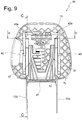
Fig. 9 eine rückwärtige Ansicht der Kopfstütze, -
Fig. 10 eine Schnittansicht der Kopfstütze gemäß Schnittlinie C - C inFig. 9 , -
Fig. 11 eine Schnittansicht gemäß Schnittlinie D - D inFig. 9 , wobei sich die Verriegelungsvorrichtung in der Riegelposition befindet, -
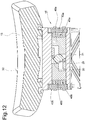
Fig. 12 eine Schnittansicht in Anlehnung anFig. 11 , wobei die Verriegelungsvorrichtung in einer Löseposition angeordnet ist, und -
Fig. 13 eine Schnittansicht in Anlehnung anFig. 10 , wobei das Kopfanlageteil in einer vorderen Position angeordnet ist. - Eine Kopfstütze gemäß einem ersten Ausführungsbeispiel insgesamt ist in den
Fig. 1 bis 6 mit dem Bezugszeichen 10 bezeichnet. - Die Kopfstütze umfasst eine Haltevorrichtung 11, die im vorliegenden Ausführungsbeispiel Tragstangen 12a und 12b aufweist. Anstelle der Tragstangen 12a und 12b könnte die Haltevorrichtung alternativ auch einen Tragstangenbügel aufweisen. Im vorliegenden Ausführungsbeispiel ist die Haltevorrichtung 11 in üblicher Weise an der Struktur einer Rückenlehne befestigbar. Ferner umfasst die Kopfstütze 10 ein Kopfanlageteil 13 mit einer Kopfanlagefläche 32, welches mit einer Verstellvorrichtung 14 derart an der Haltevorrichtung 11 gelagert ist, dass es zwischen einer in den
Fig. 1 bis 4 dargestellten vorderen Position und einer inFig. 6a dargestellten hinteren Position bewegbar ist. - Mittels einer Verriegelungsvorrichtung 15 (siehe
Fig. 2 ) ist das Kopfanlageteil in unterschiedlichen Positionen verriegelbar. - Die Verstellvorrichtung 14 umfasst einen ersten Lenker 16 sowie einen zweiten Lenker 17 hintereinander in x-Richtung. Der Lenker 16 ist u-förmig aufgebaut und umfasst Arme 18a und 18b sowie eine die Arme 18a und 18b verbindende Traverse 19. In gleicher Weise ist der Lenker 17 u-förmig ausgebildet. Er umfasst Arme 20a und 20b sowie eine Traverse 21, welche die Arme 20a und 20b verbindet. Alternativ zu dieser Ausführungsform könnten die Arme 18a und 18b und die Arme 20a und 20b nicht mittels einer Traverse untereinander verbunden sein. Mit den Traversen 19 und 21 wird aber eine höhere Stabilität erreicht.
- An einem unteren Endbereich, welcher von der Traverse 19 geformt ist, bildet der erste Lenker 16 jeweils ein Gelenk G mit den Tragstangen 12a und 12b, derart dass der erste Lenker 16 um eine Schwenkachse a1 relativ zu den Tragstangen 12a und 12b schwenkbar ist. An einem oberen Endbereich bildet jeder Arm 18a sowie 18b ein Gelenk G mit einem Tragteil 22, an welchem das Kopfanlageteil 13 höhenverstellbar gehalten ist. Auf diese Weise ist das Tragteil 22 um eine Schwenkachse a2 relativ zu dem ersten Lenker 16 schwenkbar.
- In gleicher Weise bildet der zweite Lenker 17 an einem unteren Endbereich, welcher von der Traverse 21 geformt ist, Gelenke G mit den Tragstangen 12a und 12b, so dass eine Schwenkachse a3 gebildet ist. In einem oberen Endbereich des Lenkers 17 bildet jeder Arm 20a und 20b ein Gelenk G mit dem Tragteil 22, wobei die Gelenke G eine Schwenkachse a4 definieren. Die fest angeordneten Tragstangen 12a und 12b, die Lenker 16 und 17 sowie das Tragteil 22 bilden auf diese Weise ein Koppelgetriebe. Das Kopfanlageteil 13 ist damit entlang einer Koppelkurve bewegbar an der Haltevorrichtung 11 gelagert, wobei eine Bewegung in die Richtungen x1 oder x2 und eine Bewegung in die Richtungen z1 oder z2 erfolgt.
- An einem oberen von der Haltevorrichtung 11 abgewandten Endbereich weisen der Arm 18a des ersten Lenkers 16 Verriegelungsmittel 24a und der Arm 18b Verriegelungsmittel 24b auf (siehe die
Fig. 4 und5 ). Diese sind in Form einer Verzahnung ausgebildet, die sich entlang einer Kreisbahn um die Schwenkachse a2 erstreckt. Der Kopfkreis der Kreisbahn der Verriegelungsmittel 24a ist in denFig. 6c und 6d mit 37 bezeichnet. In gleicher Weise weist der Arm 20a des zweiten Lenkers 17 an einem oberen Endbereich Verriegelungsmittel 25a und der Arm 20b Verriegelungsmittel 25b auf, die die Form einer Verzahnung haben, welche sich entlang einer Kreisbahn um die Schwenkachse a4 erstreckt. Der Kopfkreis der Kreisbahn der Verriegelungsmittel 25a ist in denFig. 6c und 6d mit 38 bezeichnet. - In einem Aufnahmeraum 26 des Tragteils 22 sind ein Riegel 28a sowie ein Riegel 28b bewegbar (Der Riegel 28b ist in
Fig. 5 lediglich durch eine gestrichelte Linie angedeutet) aufgenommen. Der Riegel 28a weist Verriegelungsmittel 35a und 36a auf, die mit den Verriegelungsmitteln 24a und 25a zusammenwirken. Der Riegel 28b weist Verriegelungsmittel 35b und 36b auf, die mit den Verriegelungsmitteln 24b und 25b zusammenwirken. Der Riegel 28a lässt sich auf diese Weise lösbar in Eingriff mit den Verriegelungsmitteln 24a und 25a der Lenker 16 und 17 bewegen. In gleicher Weise lässt sich der Riegel 28b lösbar in Eingriff mit den Verriegelungsmitteln 24b und 25b bewegen. - Wenn sich die Verriegelungsvorrichtung 15 in einer Riegelposition befindet, d.h., dass die Verriegelungsmittel 35a und 36a in Eingriff mit den Verriegelungsmitteln 24a und 25a stehen und die Verriegelungsmittel 35b und 36b mit den Verriegelungsmitteln 24b und 25b in Eingriff stehen, können sich die Lenker 16 und 17 nicht um die Achsen a2 und a4 relativ zu dem Tragteil 22 drehen, d.h., dass eine Bewegung des Kopfanlageteils 13 in wenigstens eine Richtung blockiert ist.
- In einer Löseposition der Verriegelungsvorrichtung 15 sind die Verriegelungsmittel der Riegel 27 und 28 außer Eingriff mit den Verriegelungsmitteln der Lenker 16 und 17, d.h. die Verstellvorrichtung 14 ist frei bewegbar und das Kopfanlageteil 13 kann zwischen der vorderen und der hinteren Position in die Richtungen x1 und x2 bewegt werden. Die Löseposition ist in den Fig. nicht dargestellt.
- Die Betätigung der Verriegelungsvorrichtung 15 ist nicht dargestellt. Z.B. kann an dem Kopfanlageteil 13, an dem Tragteil 22 oder an einer beliebigen anderen Stelle ein Schalter vorgesehen sein, wobei die Bewegung des Schalters auf eine Bewegung der Riegel 27 und 28 mittels einer Übertragungsvorrichtung übertragen wird. Die Bewegung der Riegel 27 und 28 erfolgt im vorliegenden Ausführungsbeispiel über einen Hebel 29 (siehe
Fig. 5 ), welcher Teil einer solchen Übertragungsvorrichtung ist. Der Hebel 29 ist um eine Schwenkachse a5 schwenkbar an dem Tragteil 22 gelagert. Der Hebel 29 weist Arme 30 und 31 auf, wobei der Arm 30 mit dem Riegel 28a und der Arm 31 mit dem Riegel 28b in Kontakt steht. Schwenkt der Hebel 29 in Richtung u1 im Uhrzeigersinn gemäßFig. 6 , werden der Riegel 28b in Richtung y1 und der Riegel 28a in Richtung y2 in die Löseposition bewegt. - Die Riegel 27 und 28 sind derart federbelastet, dass bei der Bewegung in die Löseposition eine Federenergie aufgebaut wird, welche die Riegel 28a und 28b in die Riegelposition zurück belastet. Bei einer Entlastung des Hebels 29 werden die Riegel 28a und 28b daher automatisch in die Riegelposition gemäß
Fig. 5 zurückbewegt. - Der Vollständigkeit halber ist noch zu erwähnen, dass das Kopfanlageteil 13 in die Richtungen z1 und z2 höhenverstellbar an dem Tragteil 22 geführt ist und mit einer Arretiervorrichtung 23 in unterschiedlichen Höhenpositionen arretierbar ist. Die Arretiervorrichtung 23 umfasst dem Kopfanlageteil 13 zugeordnete Arretiermittel 33 sowie dem Tragteil 22 zugeordnete Arretiermittel 34.
- Bei einem zweiten, in den
Figuren 7 bis 13 dargestellten Ausführungsbeispiel einer Kopfstütze 50, weist die Verstellvorrichtung 14 einen ersten Lenker 40 sowie einen zweiten Lenker 41 auf, die sich von den Lenkern 16 und 17 dadurch unterscheiden, dass die Lenker 40 und 41 aus Kunststoff ausgebildet sind. Wie inFig. 7 zu sehen ist, ist der erste Lenker 40 größer ausgebildet und mit Rippen 42 versehen, die der Stabilisierung dienen. - Außerdem weicht das zweite Ausführungsbeispiel von dem ersten Ausführungsbeispiel dadurch ab, dass lediglich der erste Lenker 40 Verriegelungsmitteln 43a und 43b in Form einer Verzahnung versehen ist. Die Lenker 40 und 41 haben trotz ihrer abweichenden Form ebenfalls eine u-förmige Gestalt. Der Lenker 40 ist mit Armen 44a und 44b sowie einer die Arme 44a und 44b verbindenden Traverse 45 geformt. Der Lenker 41 weist Arme 46a und 46b sowie eine die Arme 46a und 46b verbindende Traverse 47 auf. Ferner sind die Tragstangen 12a und 12b mittels eines Verbindungsteils 51 mit einander verbunden.
- Die Verriegelungsmittel 43a sind an einem oberen, von der Haltevorrichtung 11 abgewandten Endbereich des Arms 44a und die Verriegelungsmittel 43b sind an einem oberen Endbereich des Arms 44b des Lenkers 40 angeordnet. Gemäß
Fig. 12 weist die Verriegelungsvorrichtung 15 zwei Riegel 48a und 48b auf, welche in dem Aufnahmeraum 26 angeordnet sind und sich in die Richtungen y1 und y2 bewegen lassen. In der Riegelposition stehen Verriegelungsmittel 49a des Riegels 48a in Eingriff mit den Verriegelungsmitteln 43a und Verriegelungsmittel 49b des Riegels 48b in Eingriff mit den Verriegelungsmitteln 43b. - Bei einer Bewegung des Hebels 29 in Richtung u1 im Uhrzeigersinn gemäß
Fig. 12 wird der Riegel 48a entgegen der Rückstellkraft in Richtung y1 und der Riegel 48b entgegen der Rückstellkraft in Richtung y2 bewegt. Die Verriegelungsvorrichtung 15 ist dann gemäßFig. 13 in der Löseposition. Bei Entlastung des Riegels 29 werden der Riegel 48a wieder in Richtung y2 und der Riegel 48b in Richtung y1 in die Riegelposition bewegt. - In den übrigen Merkmalen stimmt das zweite Ausführungsbeispiel mit dem ersten Ausführungsbeispiel im Wesentlichen überein.
Claims (10)
- Kopfstütze mit einem Kopfanlageteil (13), welches mittels einer Haltevorrichtung (11) an einer Struktur eines Fahrzeugs, insbesondere an einem Fahrzeugsitz, lagerbar ist, wobei das Kopfanlageteil (13) relativ zu der Haltevorrichtung (11) mittels einer Verstellvorrichtung (14) nach vorne zu dem Kopf eines Benutzers und in entgegengesetzte Richtung zurück bewegbar ist, wobei die Verstellvorrichtung (14) wenigstens einen ersten Lenker (16, 40) und einen zweiten Lenker (17, 41) umfasst, wobei jeder Lenker (16, 17, 40, 41) mit einer das Kopfanlageteil (13) umfassenden Kopfanlagevorrichtung und mit der Haltevorrichtung (11) wenigstens ein Gelenk bildet und wobei mittels einer Verriegelungsvorrichtung (15) eine Relativbewegung zwischen der Haltevorrichtung (11) und dem Kopfanlageteil (13) lösbar blockierbar ist, dadurch gekennzeichnet, dass die Verriegelungsvorrichtung (14) erste Verriegelungsmittel (24a, 24b, 25a, 25b, 43a, 43b) aufweist, die an wenigstens einem Lenker (16, 17, 40) ausgebildet sind und zweite Verriegelungsmittel (35a, 35b, 36a, 36b, 49a, 49b) aufweist, die dem Kopfanlageteil (13) oder der Haltevorrichtung (11) zugeordnet sind, wobei die ersten Verriegelungsmittel und die zweiten Verriegelungsmittel lösbar in Eingriff bringbar sind.
- Kopfstütze nach Anspruch 1, dadurch gekennzeichnet, dass die ersten Verriegelungsmittel (24a, 24b, 25a, 25b, 43a, 43b) Formschlussmittel, insbesondere in Form einer Verzahnung umfassen und die zweiten Verriegelungsmittel (35a, 35b, 36a, 36b, 49a, 49b) komplementäre Formschlussmittel umfassen.
- Kopfstütze nach Anspruch 1 oder 2, dadurch gekennzeichnet, dass die ersten Verriegelungsmittel (24a, 24b, 25a, 25b, 43a, 43b) an einem oberen Endbereich des Lenkers (16, 17, 40) ausgebildet sind.
- Kopfstütze nach einem der vorangehenden Ansprüche, dadurch gekennzeichnet, dass die zweiten Verriegelungsmittel (35a, 35b, 36a, 36b, 49a, 49b) wenigstens einem bewegbaren Riegel (28a, 28b, 48a, 48b) zugeordnet sind, welcher zwischen der Riegelposition und der Löseposition bewegbar an der Kopfanlagevorrichtung oder an der Haltevorrichtung (11) gehalten ist.
- Kopfstütze nach einem der vorangehenden Ansprüche, dadurch gekennzeichnet, dass in Verstellrichtung (x1, x2) der erste Lenker (16, 40) und der zweite Lenker (17, 41) jeweils zwei parallel zueinander angeordnete Arme (18a, 18b, 20a, 20b, 44a, 44b, 46a, 46b) aufweisen und dass zwischen den parallelen Armen ein Abstand gebildet ist.
- Kopfstütze nach einem der vorangehenden Ansprüche, dadurch gekennzeichnet, dass die parallelen Arme (18a, 18b, 20a, 20b, 44a, 44b, 46a, 46b) mittels einer Traverse (19, 21, 45, 47) miteinander verbunden sind.
- Kopfstütze nach einem der vorangehenden Ansprüche, dadurch gekennzeichnet, dass jeder Arm (18a, 18b, 20a, 20b, 44a, 44b, 46a, 46b) ein Gelenk (G) mit der Kopfanlagevorrichtung und ein Gelenk (G) mit der Haltevorrichtung (11) bildet.
- Kopfstütze nach einem der vorangehenden Ansprüche, dadurch gekennzeichnet, dass die Haltevorrichtung (11) mit den Lenkern (16, 17, 40, 41) und dem Kopfanlageteil (13) ein Viergelenk bildet.
- Kopfstütze nach einem der vorangehenden Ansprüche, dadurch gekennzeichnet, dass jeder Lenker (16, 17, 40, 41) wenigstens ein Gelenk (G) mit der Haltevorrichtung (11) und ein Gelenk (G) mit einem Tragteil (22) der Kopfanlagevorrichtung bildet, an welchem das Kopfanlageteil (11), insbesondere höhenverstellbar, gelagert ist.
- Kopfstütze nach einem der vorangehenden Ansprüche, dadurch gekennzeichnet, dass der Riegel (28a, 28b, 48a, 48b) in einem Aufnahmeraum (26) bewegbar aufgenommen ist, welcher an der Kopfanlagevorrichtung ausgebildet ist.
Applications Claiming Priority (1)
| Application Number | Priority Date | Filing Date | Title |
|---|---|---|---|
| DE102018005316.5A DE102018005316A1 (de) | 2018-07-05 | 2018-07-05 | Kopfstütze |
Publications (2)
| Publication Number | Publication Date |
|---|---|
| EP3590760A1 true EP3590760A1 (de) | 2020-01-08 |
| EP3590760B1 EP3590760B1 (de) | 2023-12-06 |
Family
ID=67139588
Family Applications (1)
| Application Number | Title | Priority Date | Filing Date |
|---|---|---|---|
| EP19020413.1A Active EP3590760B1 (de) | 2018-07-05 | 2019-07-02 | Kopfstütze |
Country Status (4)
| Country | Link |
|---|---|
| US (1) | US20200039406A1 (de) |
| EP (1) | EP3590760B1 (de) |
| CN (1) | CN110682842B (de) |
| DE (1) | DE102018005316A1 (de) |
Families Citing this family (3)
| Publication number | Priority date | Publication date | Assignee | Title |
|---|---|---|---|---|
| DE102018109611B4 (de) * | 2018-04-10 | 2022-04-21 | Grammer Aktiengesellschaft | Kopfstütze |
| DE102023102433A1 (de) * | 2022-02-14 | 2023-08-17 | Grammer Aktiengesellschaft | Kopfstütze |
| DE102022122310A1 (de) | 2022-09-02 | 2024-03-07 | Grammer Aktiengesellschaft | Kopfstütze |
Citations (4)
| Publication number | Priority date | Publication date | Assignee | Title |
|---|---|---|---|---|
| WO2008068372A1 (es) * | 2006-12-05 | 2008-06-12 | Batz, S.Coop. | Reposacabezas para asientos de vehículos automóviles |
| DE102010007942A1 (de) | 2010-02-12 | 2011-08-18 | Grammer AG, 92224 | Kopfstütze für Fahrzeugsitze |
| US20120068517A1 (en) * | 2010-09-17 | 2012-03-22 | Lear Corporation | Adjustable head restraint assembly for vehicle seats |
| WO2014122379A1 (fr) * | 2013-02-07 | 2014-08-14 | Centre D'etude Et De Recherche Pour L'automobile (Cera) | Appui-tête de siège de véhicule automobile |
Family Cites Families (12)
| Publication number | Priority date | Publication date | Assignee | Title |
|---|---|---|---|---|
| US4366985A (en) * | 1981-02-13 | 1983-01-04 | Pelton & Crane | Adjustable headrest for treatment chair |
| JPS61102153U (de) * | 1984-12-12 | 1986-06-30 | ||
| DE10047406A1 (de) * | 2000-09-26 | 2002-04-11 | Daimler Chrysler Ag | Kopfstütze |
| KR100510152B1 (ko) * | 2003-04-14 | 2005-08-26 | 주식회사 우보테크 | 자동차용 헤드레스트 |
| US7636968B2 (en) * | 2005-06-14 | 2009-12-29 | Earthlite Massage Tables, Inc. | Flexible headrest assembly with non-skid contact for a massage device |
| DE102009019439B3 (de) * | 2008-11-10 | 2010-06-24 | Grammer Ag | Kopfstütze für Fahrzeugsitze |
| KR101553527B1 (ko) * | 2014-03-17 | 2015-09-17 | 현대다이모스(주) | 전동식 헤드레스트 |
| BR102015008502A2 (pt) * | 2014-04-21 | 2015-10-27 | Ford Global Tech Llc | conector elétrico de apoio de cabeça motorizado |
| KR101570427B1 (ko) * | 2014-07-11 | 2015-11-19 | 주식회사 우보테크 | 헤드레스트 이동장치 |
| JP5902847B1 (ja) * | 2015-05-14 | 2016-04-13 | 備前発条株式会社 | ヘッドレスト |
| DE102017001149B4 (de) * | 2017-02-08 | 2025-02-20 | Grammer Aktiengesellschaft | Kopfstütze |
| DE102018106698A1 (de) * | 2018-03-21 | 2019-09-26 | Grammer Ag | Kopfstütze |
-
2018
- 2018-07-05 DE DE102018005316.5A patent/DE102018005316A1/de not_active Withdrawn
-
2019
- 2019-07-01 US US16/458,620 patent/US20200039406A1/en not_active Abandoned
- 2019-07-02 EP EP19020413.1A patent/EP3590760B1/de active Active
- 2019-07-05 CN CN201910601217.0A patent/CN110682842B/zh active Active
Patent Citations (4)
| Publication number | Priority date | Publication date | Assignee | Title |
|---|---|---|---|---|
| WO2008068372A1 (es) * | 2006-12-05 | 2008-06-12 | Batz, S.Coop. | Reposacabezas para asientos de vehículos automóviles |
| DE102010007942A1 (de) | 2010-02-12 | 2011-08-18 | Grammer AG, 92224 | Kopfstütze für Fahrzeugsitze |
| US20120068517A1 (en) * | 2010-09-17 | 2012-03-22 | Lear Corporation | Adjustable head restraint assembly for vehicle seats |
| WO2014122379A1 (fr) * | 2013-02-07 | 2014-08-14 | Centre D'etude Et De Recherche Pour L'automobile (Cera) | Appui-tête de siège de véhicule automobile |
Also Published As
| Publication number | Publication date |
|---|---|
| CN110682842A (zh) | 2020-01-14 |
| CN110682842B (zh) | 2022-06-14 |
| US20200039406A1 (en) | 2020-02-06 |
| EP3590760B1 (de) | 2023-12-06 |
| DE102018005316A1 (de) | 2020-01-09 |
Similar Documents
| Publication | Publication Date | Title |
|---|---|---|
| DE4012860C2 (de) | Freischwenkeinrichtung für die Rückenlehne eines Fahrzeugsitzes, insbesondere Kraftfahrzeugsitzes | |
| DE102014107816B4 (de) | Nutzfahrzeugsitz mit arretierbarem Querschlittenteil | |
| EP2746103B1 (de) | Nutzfahrzeugsitz mit doppelarretierbarem querschlittenteil | |
| EP0022933B1 (de) | Sitz mit neigungsverstellbarer Sitzplatte und neigungsverstellbarer Rückenlehne | |
| DE102019001280B4 (de) | Messer | |
| EP3188929B1 (de) | Armlehne | |
| EP3590760B1 (de) | Kopfstütze | |
| DE4417491C2 (de) | Fanghaken zur lösbaren Verriegelung der mit dem Sitzteil eines Fahrzeugsitzes vorschwenkbar verbundenen Rückenlehne | |
| DE102018109611B4 (de) | Kopfstütze | |
| EP4054302B1 (de) | Anbaudrehpflug | |
| DE4022391C1 (en) | Frame for perambulator - has foldable frame tubes with latches to hold in selected position | |
| EP3885010B1 (de) | Ferseneinheit für tourenbindung mit auslösemechanismus und erleichtete einstellung | |
| EP3848242B1 (de) | Kopfstütze | |
| EP3831650B1 (de) | Ausstattungsvorrichtung | |
| EP3827938B1 (de) | Messer | |
| DE102012009578B4 (de) | Armlehne für Fahrzeugsitze | |
| DE102008059355B4 (de) | Beschlagsystem für einen Fahrzeugsitz sowie Fahrzeugsitz mit einem solchen Beschlagsystem | |
| DE102008011560B3 (de) | Verriegelungsvorrichtung, insbesondere für eine Kopfstütze für Fahrzeugsitze | |
| DE102005005826B4 (de) | Kopfstütze | |
| DE102019001283B4 (de) | Messer | |
| DE102011014620A1 (de) | Schwenkklappenvorrichtung für Fahrzeuginnenräume | |
| EP3868636A1 (de) | Tretroller | |
| DE102014212598B4 (de) | Verstellbarer Fahrzeugsitz | |
| EP1721806A2 (de) | Anordnung einer Lenksäule | |
| EP2566668B1 (de) | Messer |
Legal Events
| Date | Code | Title | Description |
|---|---|---|---|
| PUAI | Public reference made under article 153(3) epc to a published international application that has entered the european phase |
Free format text: ORIGINAL CODE: 0009012 |
|
| STAA | Information on the status of an ep patent application or granted ep patent |
Free format text: STATUS: THE APPLICATION HAS BEEN PUBLISHED |
|
| AK | Designated contracting states |
Kind code of ref document: A1 Designated state(s): AL AT BE BG CH CY CZ DE DK EE ES FI FR GB GR HR HU IE IS IT LI LT LU LV MC MK MT NL NO PL PT RO RS SE SI SK SM TR |
|
| AX | Request for extension of the european patent |
Extension state: BA ME |
|
| STAA | Information on the status of an ep patent application or granted ep patent |
Free format text: STATUS: REQUEST FOR EXAMINATION WAS MADE |
|
| 17P | Request for examination filed |
Effective date: 20200702 |
|
| RBV | Designated contracting states (corrected) |
Designated state(s): AL AT BE BG CH CY CZ DE DK EE ES FI FR GB GR HR HU IE IS IT LI LT LU LV MC MK MT NL NO PL PT RO RS SE SI SK SM TR |
|
| RAP1 | Party data changed (applicant data changed or rights of an application transferred) |
Owner name: GRAMMER AG |
|
| STAA | Information on the status of an ep patent application or granted ep patent |
Free format text: STATUS: EXAMINATION IS IN PROGRESS |
|
| 17Q | First examination report despatched |
Effective date: 20220314 |
|
| GRAP | Despatch of communication of intention to grant a patent |
Free format text: ORIGINAL CODE: EPIDOSNIGR1 |
|
| STAA | Information on the status of an ep patent application or granted ep patent |
Free format text: STATUS: GRANT OF PATENT IS INTENDED |
|
| INTG | Intention to grant announced |
Effective date: 20230801 |
|
| GRAS | Grant fee paid |
Free format text: ORIGINAL CODE: EPIDOSNIGR3 |
|
| GRAA | (expected) grant |
Free format text: ORIGINAL CODE: 0009210 |
|
| STAA | Information on the status of an ep patent application or granted ep patent |
Free format text: STATUS: THE PATENT HAS BEEN GRANTED |
|
| AK | Designated contracting states |
Kind code of ref document: B1 Designated state(s): AL AT BE BG CH CY CZ DE DK EE ES FI FR GB GR HR HU IE IS IT LI LT LU LV MC MK MT NL NO PL PT RO RS SE SI SK SM TR |
|
| REG | Reference to a national code |
Ref country code: GB Ref legal event code: FG4D Free format text: NOT ENGLISH |
|
| REG | Reference to a national code |
Ref country code: CH Ref legal event code: EP |
|
| REG | Reference to a national code |
Ref country code: DE Ref legal event code: R096 Ref document number: 502019010053 Country of ref document: DE |
|
| P01 | Opt-out of the competence of the unified patent court (upc) registered |
Effective date: 20231120 |
|
| REG | Reference to a national code |
Ref country code: IE Ref legal event code: FG4D Free format text: LANGUAGE OF EP DOCUMENT: GERMAN |
|
| REG | Reference to a national code |
Ref country code: LT Ref legal event code: MG9D |
|
| PG25 | Lapsed in a contracting state [announced via postgrant information from national office to epo] |
Ref country code: GR Free format text: LAPSE BECAUSE OF FAILURE TO SUBMIT A TRANSLATION OF THE DESCRIPTION OR TO PAY THE FEE WITHIN THE PRESCRIBED TIME-LIMIT Effective date: 20240307 |
|
| REG | Reference to a national code |
Ref country code: NL Ref legal event code: MP Effective date: 20231206 |
|
| PG25 | Lapsed in a contracting state [announced via postgrant information from national office to epo] |
Ref country code: LT Free format text: LAPSE BECAUSE OF FAILURE TO SUBMIT A TRANSLATION OF THE DESCRIPTION OR TO PAY THE FEE WITHIN THE PRESCRIBED TIME-LIMIT Effective date: 20231206 |
|
| PG25 | Lapsed in a contracting state [announced via postgrant information from national office to epo] |
Ref country code: ES Free format text: LAPSE BECAUSE OF FAILURE TO SUBMIT A TRANSLATION OF THE DESCRIPTION OR TO PAY THE FEE WITHIN THE PRESCRIBED TIME-LIMIT Effective date: 20231206 |
|
| PG25 | Lapsed in a contracting state [announced via postgrant information from national office to epo] |
Ref country code: LT Free format text: LAPSE BECAUSE OF FAILURE TO SUBMIT A TRANSLATION OF THE DESCRIPTION OR TO PAY THE FEE WITHIN THE PRESCRIBED TIME-LIMIT Effective date: 20231206 Ref country code: GR Free format text: LAPSE BECAUSE OF FAILURE TO SUBMIT A TRANSLATION OF THE DESCRIPTION OR TO PAY THE FEE WITHIN THE PRESCRIBED TIME-LIMIT Effective date: 20240307 Ref country code: ES Free format text: LAPSE BECAUSE OF FAILURE TO SUBMIT A TRANSLATION OF THE DESCRIPTION OR TO PAY THE FEE WITHIN THE PRESCRIBED TIME-LIMIT Effective date: 20231206 Ref country code: BG Free format text: LAPSE BECAUSE OF FAILURE TO SUBMIT A TRANSLATION OF THE DESCRIPTION OR TO PAY THE FEE WITHIN THE PRESCRIBED TIME-LIMIT Effective date: 20240306 |
|
| PG25 | Lapsed in a contracting state [announced via postgrant information from national office to epo] |
Ref country code: NL Free format text: LAPSE BECAUSE OF FAILURE TO SUBMIT A TRANSLATION OF THE DESCRIPTION OR TO PAY THE FEE WITHIN THE PRESCRIBED TIME-LIMIT Effective date: 20231206 |
|
| PG25 | Lapsed in a contracting state [announced via postgrant information from national office to epo] |
Ref country code: SE Free format text: LAPSE BECAUSE OF FAILURE TO SUBMIT A TRANSLATION OF THE DESCRIPTION OR TO PAY THE FEE WITHIN THE PRESCRIBED TIME-LIMIT Effective date: 20231206 Ref country code: RS Free format text: LAPSE BECAUSE OF FAILURE TO SUBMIT A TRANSLATION OF THE DESCRIPTION OR TO PAY THE FEE WITHIN THE PRESCRIBED TIME-LIMIT Effective date: 20231206 Ref country code: NO Free format text: LAPSE BECAUSE OF FAILURE TO SUBMIT A TRANSLATION OF THE DESCRIPTION OR TO PAY THE FEE WITHIN THE PRESCRIBED TIME-LIMIT Effective date: 20240306 Ref country code: NL Free format text: LAPSE BECAUSE OF FAILURE TO SUBMIT A TRANSLATION OF THE DESCRIPTION OR TO PAY THE FEE WITHIN THE PRESCRIBED TIME-LIMIT Effective date: 20231206 Ref country code: LV Free format text: LAPSE BECAUSE OF FAILURE TO SUBMIT A TRANSLATION OF THE DESCRIPTION OR TO PAY THE FEE WITHIN THE PRESCRIBED TIME-LIMIT Effective date: 20231206 Ref country code: HR Free format text: LAPSE BECAUSE OF FAILURE TO SUBMIT A TRANSLATION OF THE DESCRIPTION OR TO PAY THE FEE WITHIN THE PRESCRIBED TIME-LIMIT Effective date: 20231206 |
|
| PG25 | Lapsed in a contracting state [announced via postgrant information from national office to epo] |
Ref country code: IS Free format text: LAPSE BECAUSE OF FAILURE TO SUBMIT A TRANSLATION OF THE DESCRIPTION OR TO PAY THE FEE WITHIN THE PRESCRIBED TIME-LIMIT Effective date: 20240406 |
|
| PG25 | Lapsed in a contracting state [announced via postgrant information from national office to epo] |
Ref country code: CZ Free format text: LAPSE BECAUSE OF FAILURE TO SUBMIT A TRANSLATION OF THE DESCRIPTION OR TO PAY THE FEE WITHIN THE PRESCRIBED TIME-LIMIT Effective date: 20231206 |
|
| PG25 | Lapsed in a contracting state [announced via postgrant information from national office to epo] |
Ref country code: SK Free format text: LAPSE BECAUSE OF FAILURE TO SUBMIT A TRANSLATION OF THE DESCRIPTION OR TO PAY THE FEE WITHIN THE PRESCRIBED TIME-LIMIT Effective date: 20231206 |
|
| PG25 | Lapsed in a contracting state [announced via postgrant information from national office to epo] |
Ref country code: SM Free format text: LAPSE BECAUSE OF FAILURE TO SUBMIT A TRANSLATION OF THE DESCRIPTION OR TO PAY THE FEE WITHIN THE PRESCRIBED TIME-LIMIT Effective date: 20231206 Ref country code: SK Free format text: LAPSE BECAUSE OF FAILURE TO SUBMIT A TRANSLATION OF THE DESCRIPTION OR TO PAY THE FEE WITHIN THE PRESCRIBED TIME-LIMIT Effective date: 20231206 Ref country code: RO Free format text: LAPSE BECAUSE OF FAILURE TO SUBMIT A TRANSLATION OF THE DESCRIPTION OR TO PAY THE FEE WITHIN THE PRESCRIBED TIME-LIMIT Effective date: 20231206 Ref country code: IS Free format text: LAPSE BECAUSE OF FAILURE TO SUBMIT A TRANSLATION OF THE DESCRIPTION OR TO PAY THE FEE WITHIN THE PRESCRIBED TIME-LIMIT Effective date: 20240406 Ref country code: EE Free format text: LAPSE BECAUSE OF FAILURE TO SUBMIT A TRANSLATION OF THE DESCRIPTION OR TO PAY THE FEE WITHIN THE PRESCRIBED TIME-LIMIT Effective date: 20231206 Ref country code: CZ Free format text: LAPSE BECAUSE OF FAILURE TO SUBMIT A TRANSLATION OF THE DESCRIPTION OR TO PAY THE FEE WITHIN THE PRESCRIBED TIME-LIMIT Effective date: 20231206 |
|
| PG25 | Lapsed in a contracting state [announced via postgrant information from national office to epo] |
Ref country code: PL Free format text: LAPSE BECAUSE OF FAILURE TO SUBMIT A TRANSLATION OF THE DESCRIPTION OR TO PAY THE FEE WITHIN THE PRESCRIBED TIME-LIMIT Effective date: 20231206 Ref country code: PT Free format text: LAPSE BECAUSE OF FAILURE TO SUBMIT A TRANSLATION OF THE DESCRIPTION OR TO PAY THE FEE WITHIN THE PRESCRIBED TIME-LIMIT Effective date: 20240408 |
|
| PG25 | Lapsed in a contracting state [announced via postgrant information from national office to epo] |
Ref country code: PT Free format text: LAPSE BECAUSE OF FAILURE TO SUBMIT A TRANSLATION OF THE DESCRIPTION OR TO PAY THE FEE WITHIN THE PRESCRIBED TIME-LIMIT Effective date: 20240408 Ref country code: PL Free format text: LAPSE BECAUSE OF FAILURE TO SUBMIT A TRANSLATION OF THE DESCRIPTION OR TO PAY THE FEE WITHIN THE PRESCRIBED TIME-LIMIT Effective date: 20231206 |
|
| REG | Reference to a national code |
Ref country code: DE Ref legal event code: R097 Ref document number: 502019010053 Country of ref document: DE |
|
| PG25 | Lapsed in a contracting state [announced via postgrant information from national office to epo] |
Ref country code: DK Free format text: LAPSE BECAUSE OF FAILURE TO SUBMIT A TRANSLATION OF THE DESCRIPTION OR TO PAY THE FEE WITHIN THE PRESCRIBED TIME-LIMIT Effective date: 20231206 |
|
| PLBE | No opposition filed within time limit |
Free format text: ORIGINAL CODE: 0009261 |
|
| STAA | Information on the status of an ep patent application or granted ep patent |
Free format text: STATUS: NO OPPOSITION FILED WITHIN TIME LIMIT |
|
| PG25 | Lapsed in a contracting state [announced via postgrant information from national office to epo] |
Ref country code: SI Free format text: LAPSE BECAUSE OF FAILURE TO SUBMIT A TRANSLATION OF THE DESCRIPTION OR TO PAY THE FEE WITHIN THE PRESCRIBED TIME-LIMIT Effective date: 20231206 |
|
| PG25 | Lapsed in a contracting state [announced via postgrant information from national office to epo] |
Ref country code: SI Free format text: LAPSE BECAUSE OF FAILURE TO SUBMIT A TRANSLATION OF THE DESCRIPTION OR TO PAY THE FEE WITHIN THE PRESCRIBED TIME-LIMIT Effective date: 20231206 Ref country code: DK Free format text: LAPSE BECAUSE OF FAILURE TO SUBMIT A TRANSLATION OF THE DESCRIPTION OR TO PAY THE FEE WITHIN THE PRESCRIBED TIME-LIMIT Effective date: 20231206 |
|
| 26N | No opposition filed |
Effective date: 20240909 |
|
| PG25 | Lapsed in a contracting state [announced via postgrant information from national office to epo] |
Ref country code: MC Free format text: LAPSE BECAUSE OF FAILURE TO SUBMIT A TRANSLATION OF THE DESCRIPTION OR TO PAY THE FEE WITHIN THE PRESCRIBED TIME-LIMIT Effective date: 20231206 |
|
| REG | Reference to a national code |
Ref country code: CH Ref legal event code: PL |
|
| PG25 | Lapsed in a contracting state [announced via postgrant information from national office to epo] |
Ref country code: LU Free format text: LAPSE BECAUSE OF NON-PAYMENT OF DUE FEES Effective date: 20240702 |
|
| GBPC | Gb: european patent ceased through non-payment of renewal fee |
Effective date: 20240702 |
|
| PG25 | Lapsed in a contracting state [announced via postgrant information from national office to epo] |
Ref country code: LU Free format text: LAPSE BECAUSE OF NON-PAYMENT OF DUE FEES Effective date: 20240702 |
|
| PG25 | Lapsed in a contracting state [announced via postgrant information from national office to epo] |
Ref country code: CH Free format text: LAPSE BECAUSE OF NON-PAYMENT OF DUE FEES Effective date: 20240731 Ref country code: BE Free format text: LAPSE BECAUSE OF NON-PAYMENT OF DUE FEES Effective date: 20240731 |
|
| PG25 | Lapsed in a contracting state [announced via postgrant information from national office to epo] |
Ref country code: GB Free format text: LAPSE BECAUSE OF NON-PAYMENT OF DUE FEES Effective date: 20240702 |
|
| REG | Reference to a national code |
Ref country code: BE Ref legal event code: MM Effective date: 20240731 |
|
| PG25 | Lapsed in a contracting state [announced via postgrant information from national office to epo] |
Ref country code: IE Free format text: LAPSE BECAUSE OF NON-PAYMENT OF DUE FEES Effective date: 20240702 |
|
| REG | Reference to a national code |
Ref country code: AT Ref legal event code: MM01 Ref document number: 1638084 Country of ref document: AT Kind code of ref document: T Effective date: 20240702 |
|
| PG25 | Lapsed in a contracting state [announced via postgrant information from national office to epo] |
Ref country code: FI Free format text: LAPSE BECAUSE OF FAILURE TO SUBMIT A TRANSLATION OF THE DESCRIPTION OR TO PAY THE FEE WITHIN THE PRESCRIBED TIME-LIMIT Effective date: 20231207 |
|
| PGFP | Annual fee paid to national office [announced via postgrant information from national office to epo] |
Ref country code: DE Payment date: 20250722 Year of fee payment: 7 |
|
| PGFP | Annual fee paid to national office [announced via postgrant information from national office to epo] |
Ref country code: IT Payment date: 20250731 Year of fee payment: 7 |
|
| PG25 | Lapsed in a contracting state [announced via postgrant information from national office to epo] |
Ref country code: AT Free format text: LAPSE BECAUSE OF NON-PAYMENT OF DUE FEES Effective date: 20240702 |
|
| PGFP | Annual fee paid to national office [announced via postgrant information from national office to epo] |
Ref country code: FR Payment date: 20250723 Year of fee payment: 7 |
|
| PG25 | Lapsed in a contracting state [announced via postgrant information from national office to epo] |
Ref country code: CY Free format text: LAPSE BECAUSE OF FAILURE TO SUBMIT A TRANSLATION OF THE DESCRIPTION OR TO PAY THE FEE WITHIN THE PRESCRIBED TIME-LIMIT; INVALID AB INITIO Effective date: 20190702 |
|
| PG25 | Lapsed in a contracting state [announced via postgrant information from national office to epo] |
Ref country code: HU Free format text: LAPSE BECAUSE OF FAILURE TO SUBMIT A TRANSLATION OF THE DESCRIPTION OR TO PAY THE FEE WITHIN THE PRESCRIBED TIME-LIMIT; INVALID AB INITIO Effective date: 20190702 |