EP3589876B1 - Quick connector - Google Patents
Quick connector Download PDFInfo
- Publication number
- EP3589876B1 EP3589876B1 EP18701699.3A EP18701699A EP3589876B1 EP 3589876 B1 EP3589876 B1 EP 3589876B1 EP 18701699 A EP18701699 A EP 18701699A EP 3589876 B1 EP3589876 B1 EP 3589876B1
- Authority
- EP
- European Patent Office
- Prior art keywords
- bending portion
- quick connector
- snap hooks
- bending
- snap
- Prior art date
- Legal status (The legal status is an assumption and is not a legal conclusion. Google has not performed a legal analysis and makes no representation as to the accuracy of the status listed.)
- Active
Links
Images

Classifications
-
- F—MECHANICAL ENGINEERING; LIGHTING; HEATING; WEAPONS; BLASTING
- F16—ENGINEERING ELEMENTS AND UNITS; GENERAL MEASURES FOR PRODUCING AND MAINTAINING EFFECTIVE FUNCTIONING OF MACHINES OR INSTALLATIONS; THERMAL INSULATION IN GENERAL
- F16L—PIPES; JOINTS OR FITTINGS FOR PIPES; SUPPORTS FOR PIPES, CABLES OR PROTECTIVE TUBING; MEANS FOR THERMAL INSULATION IN GENERAL
- F16L37/00—Couplings of the quick-acting type
- F16L37/08—Couplings of the quick-acting type in which the connection between abutting or axially overlapping ends is maintained by locking members
- F16L37/084—Couplings of the quick-acting type in which the connection between abutting or axially overlapping ends is maintained by locking members combined with automatic locking
- F16L37/098—Couplings of the quick-acting type in which the connection between abutting or axially overlapping ends is maintained by locking members combined with automatic locking by means of flexible hooks
- F16L37/0985—Couplings of the quick-acting type in which the connection between abutting or axially overlapping ends is maintained by locking members combined with automatic locking by means of flexible hooks the flexible hook extending radially inwardly from an outer part and engaging a bead, recess or the like on an inner part
-
- F—MECHANICAL ENGINEERING; LIGHTING; HEATING; WEAPONS; BLASTING
- F16—ENGINEERING ELEMENTS AND UNITS; GENERAL MEASURES FOR PRODUCING AND MAINTAINING EFFECTIVE FUNCTIONING OF MACHINES OR INSTALLATIONS; THERMAL INSULATION IN GENERAL
- F16L—PIPES; JOINTS OR FITTINGS FOR PIPES; SUPPORTS FOR PIPES, CABLES OR PROTECTIVE TUBING; MEANS FOR THERMAL INSULATION IN GENERAL
- F16L37/00—Couplings of the quick-acting type
- F16L37/08—Couplings of the quick-acting type in which the connection between abutting or axially overlapping ends is maintained by locking members
- F16L37/084—Couplings of the quick-acting type in which the connection between abutting or axially overlapping ends is maintained by locking members combined with automatic locking
- F16L37/098—Couplings of the quick-acting type in which the connection between abutting or axially overlapping ends is maintained by locking members combined with automatic locking by means of flexible hooks
-
- F—MECHANICAL ENGINEERING; LIGHTING; HEATING; WEAPONS; BLASTING
- F16—ENGINEERING ELEMENTS AND UNITS; GENERAL MEASURES FOR PRODUCING AND MAINTAINING EFFECTIVE FUNCTIONING OF MACHINES OR INSTALLATIONS; THERMAL INSULATION IN GENERAL
- F16L—PIPES; JOINTS OR FITTINGS FOR PIPES; SUPPORTS FOR PIPES, CABLES OR PROTECTIVE TUBING; MEANS FOR THERMAL INSULATION IN GENERAL
- F16L37/00—Couplings of the quick-acting type
- F16L37/08—Couplings of the quick-acting type in which the connection between abutting or axially overlapping ends is maintained by locking members
- F16L37/12—Couplings of the quick-acting type in which the connection between abutting or axially overlapping ends is maintained by locking members using hooks, pawls, or other movable or insertable locking members
- F16L37/133—Couplings of the quick-acting type in which the connection between abutting or axially overlapping ends is maintained by locking members using hooks, pawls, or other movable or insertable locking members using flexible hooks
-
- F—MECHANICAL ENGINEERING; LIGHTING; HEATING; WEAPONS; BLASTING
- F16—ENGINEERING ELEMENTS AND UNITS; GENERAL MEASURES FOR PRODUCING AND MAINTAINING EFFECTIVE FUNCTIONING OF MACHINES OR INSTALLATIONS; THERMAL INSULATION IN GENERAL
- F16L—PIPES; JOINTS OR FITTINGS FOR PIPES; SUPPORTS FOR PIPES, CABLES OR PROTECTIVE TUBING; MEANS FOR THERMAL INSULATION IN GENERAL
- F16L37/00—Couplings of the quick-acting type
- F16L37/08—Couplings of the quick-acting type in which the connection between abutting or axially overlapping ends is maintained by locking members
- F16L37/12—Couplings of the quick-acting type in which the connection between abutting or axially overlapping ends is maintained by locking members using hooks, pawls, or other movable or insertable locking members
- F16L37/138—Couplings of the quick-acting type in which the connection between abutting or axially overlapping ends is maintained by locking members using hooks, pawls, or other movable or insertable locking members using an axially movable sleeve
Definitions
- the present invention relates generally to the field of quick connectors. More specifically, the present document discloses a quick connector with an improved locking mechanism.
- Quick connectors for coupling a hose with a water tap, a hose cart or a spray head are known in prior art.
- the quick connector comprises a hose receiving portion and - opposite to said hose receiving portion - a receiving area for receiving a male coupling element.
- the quick connector further comprises a locking mechanism for securing the male coupling element in an inserted position, i.e. in a position in which a portion of the male coupling element is inserted in the receiving area of the quick connector.
- US 4,681,350 discloses a quick coupling connection comprising a male element with an outer engagement groove and a receiving portion in the form of a female element to axially receive the male element and provided with two diametrically opposing apertures. Interposed between said female element and, collar, two teeth are inserted into the apertures of the female teeth radially outwardly into engagement with the inner surface of the collar.
- Elastic means comprise two identical annular elements interposed between strips and in the form of an ellipse with its major axis orthogonal to the axis of the coupling. The annular elements are each curving about their major axis and the strips and annular elements are connected to a common circular base ring resting on a widened part of the receiving portion.
- Respective projections on the inner surface of the collar against which said elliptical elastic elements press and protuberance on said collar for retaining the teeth in their locking position are provided.
- the collar has beyond said protuberances widened spaces into which the teeth are inserted by the strips when the teeth are released from the projections.
- the collar is left in its locking position with the protuberances opposing the elastic action of the strips to keep the teeth inserted through the apertures and partly into the receiving portion of the female element.
- the male element acts on the teeth to cause them to rotate about their points of contact with the protuberances with simultaneous elastic deformation of the strips and complete emergence from the apertures.
- In order to release it is necessary only to pull the collar in a direction away against the elastic thrust of rings so that the protuberances become disposed below the teeth to release them and the strips which are no longer retained extract the teeth from the respective apertures.
- the invention relates to a quick connector for coupling a hose at a male coupling element.
- Said male coupling element may be provided at a liquid providing entity (e.g. water tap) or liquid receiving entity (e.g. spray head).
- a liquid providing entity e.g. water tap
- liquid receiving entity e.g. spray head
- the male coupling element comprises a connector main body with a hose receiving portion, a receiving area adapted to receive a portion of said male coupling element and a locking mechanism adapted to lock the male coupling element at the quick connector in a position in which said male coupling element is partially inserted in said receiving area.
- the locking mechanism comprises two or more snap hooks adapted to interact with a groove or recess provided at the male coupling element in order to lock the male coupling element in the inserted state.
- Said snap hooks comprise a foot portion, an upper portion forming an engagement portion and a bending portion being arranged between said foot portion and said upper portion.
- the bending portion comprises a tapered shape, wherein the thickness of the bending portion is increasing towards the upper portion. Said thickness may be measured in radial direction with respect to the central axis of the quick connector.
- Said quick connector is advantageous because the due to tapered shape of the snap hooks improved bending properties and restoring forces of the snap hooks are obtained.
- the thickness of the bending portion close to the transition area between the upper portion and the bending portion is greater than the thickness of the bending portion in a centre area of said bending portion.
- the thickness of the bending portion close to the transition area between the foot portion and the bending portion is greater than the thickness of the bending portion in a centre area of said bending portion.
- the bending portion may be waisted or waist-shaped in a centre area.
- the effective length of the lever arm of the snap hook can be chosen as desired.
- the snap hook comprises a front side at which a hook portion (also referred to as engagement portion) protrudes and a back side opposite to said front side, wherein said back side comprises a concave shape.
- Said hook portion may be directed towards the central axis of the quick connector and may protrude through an opening into the receiving area of the connector main body.
- the back side may face away from said central axis and may face a movable sleeve arranged around the connector main body.
- Said movable sleeve may be adapted to deactivate the locking mechanism in order to be able to remove the male coupling element from the quick connector. Due to the concave shape, the bending properties of the snap hook, specifically in the centre area of the bending portion, are further improved.
- said concavely-shaped surface provided at the back side spans from the bending portion into the upper portion.
- said bending portion thickens towards the foot portion.
- the bending region is shifted towards the centre area of the bending portion, i.e. the bending of the snap hook occurs at a distance from the foot portion.
- the bending portion comprises a straight or concavely-shaped surface at the front side which is arranged in a centre area of said bending portion.
- the snap hook comprises at its front side a rounded, concavely-shaped transition area arranged between the bending portion and the upper portion, specifically the hook portion.
- Said transition area may form a contact surface which interacts with an edge of an opening provided in the circumferential wall of the connector main body.
- a hook portion provided at the upper portion comprises multiple planar surfaces which are connected by multiple edges or rounded transitions.
- the inclinations and dimensions of said planar surfaces may be adapted to the groove or recess provided in the male coupling element in order to enable a form-fitted engaging of the hook portion into said groove or recess.
- said two or more snap hooks are coupled by means of a coupling ring.
- Said coupling ring may be provided at a lower free end of the snap hooks.
- One or more spring elements are provided between said at least two snap hooks. Said spring elements may be adapted to push a sleeve circumferentially provided at the connector main body in an upper position. In order to deactivate the locking mechanism, the sleeve has to be moved against the spring force of the spring elements in a retracted position.
- said spring element comprises an oval-shaped spring body and bar-shaped top and bottom portions.
- the legs of the oval-shaped spring body provide deformable portions which provide the spring forces.
- the oval-shaped spring body may extend along an angular range of 30° to 60°.
- the spring body may comprise multiple X-shaped spring portions or may comprise a lattice-like structure.
- the bar-shaped top and bottom portions provide increased contact surfaces for abutting against the sleeve, respectively, the connector main body.
- the bar-shaped top and bottom portions may be arranged perpendicular with respect to the central axis of the quick connector.
- Said spring elements and snap hooks are coupled with each other by means of a coupling ring. Thereby, the assembling effort is further improved.
- the spring elements, snap hooks and the coupling ring may be manufactured using a two-component injection moulding process or multi-component injection moulding process.
- thermoplastic polymers may be used which are incompatible such that said thermoplastic polymers no not mix but stay separated from each other. However, said polymers are adhered against each other such that a single-piece element comprising the spring elements, snap hooks and the coupling ring is obtained.
- different polymers can be used for building the spring elements, the snap hooks and the coupling ring.
- Said polymers may comprise properties adapted to the specific tasks of the spring elements, the snap hooks and the coupling ring.
- the spring element and/or the snap hook itself can be manufactured using different polymers, e.g. a harder polymer for the upper portion and a more flexible polymer for the bending portion of the snap hook.
- polymer herein includes any polymer material and mixtures of polymer materials and co-polymer materials, in particular thermoplastic polymers.
- said connector main body comprises one or more stop portions at which the snap hooks, the spring elements and/or the coupling ring rest on.
- Said stop portion may be a protrusion, shoulder or collar radially protruding from the wall portion of the connector main body.
- Said snap hooks and/or the coupling ring and/or the spring elements may abut against said one or more stop portions. Thereby the stop portion provides a support for said elements.
- the stop portion of the connector main body, the foot portions of the snap hooks, the spring elements and/or the coupling ring are over-moulded using a 2-component- or multi-component-injection moulding technique.
- a secure fixing of the snap hooks, the spring elements and/or the coupling ring at the connector main body is obtained.
- the fixing of the coupling element is obtained by a tight fit and/or a form fit of the coupling ring at the connector main body.
- the spring elements are included in the sleeve.
- Said spring elements may be formed at the inner surface of the sleeve using a 2-component- or multi-component-injection moulding technique.
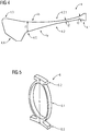
- Fig. 1 illustrates an example embodiment of a quick connector 1.
- the quick connector 1 may be a female coupling element which interacts with a male coupling element in order to provide a detachable connection, for example, between a hose and a water tap.
- Said quick connector 1 comprises a connector main body 2 with a hose receiving portion 2.1 and a receiving area 2.2.
- Said hose receiving portion 2.1 may be adapted to receive a free end of a hose and couple said free end of the hose with a liquid channel provided within the connector main body 2.
- Said hose receiving portion 2.1 may provide clamping means for clamping the hose at the hose receiving portion 2.1.
- the receiving area 2.2 may be adapted to receive a portion of the male coupling element.
- Said receiving area 2.2 may be provided opposite to the hose receiving portion 2.1.
- the receiving area 2.2 may be a recess in which a front portion of the male coupling element can be inserted.
- a locking mechanism 3 is provided at the quick connector 1.
- Said locking mechanism 3 is adapted to secure the male coupling element in the inserted position if said front portion of the male coupling element is inserted in the receiving area 2.2.
- Said locking mechanism 3 may comprise two or more snap hooks 4 which are adapted to interact with a groove or recess provided at the male coupling element in order to lock the male coupling element in the inserted position.
- Said two or more snap hooks 4 may be circumferentially distributed around the connector main body 2, e.g. equally distributed based on a given angular distance.
- the snap hooks 4 are flexible in order to be bent inwardly and outwardly (with respect to a central axis A of the connector main body 2).
- Each snap hook 4 may comprise an upper portion 4.3 forming an engagement portion or hook portion 4.4 which protrudes through an opening 2.4 provided in the connector main body 2 into the receiving area 2.2.
- the engagement portion or hook portion 4.4 of each snap hook 4 engages into the groove or recess provided at the male coupling element thereby avoiding that the male coupling element can be pulled out of said receiving area 2.2.
- the locking mechanism 3 further comprises a sleeve 3.1 movably, preferably slidably mounted at the quick connector 1.
- the sleeve 3.1 may surround the connector main body 2 in an area in which said snap hooks 4 are provided.
- Said sleeve 3.1 may be springloaded. By means of one or more spring elements 6, the sleeve 3.1 is pushed in a first position. By applying forces to said sleeve 3.1, said sleeve 3.1 can be pushed or pulled in a second position, specifically in a retracted position.
- Said sleeve 3.1 may interact with the snap hooks 4 such that said snap hooks 4 can not be bent outwardly in case that the sleeve 3.1 is in the first position.
- the snap hooks 4 can be bent outwardly thereby releasing the snap connection with the male coupling element. Thereby, the male coupling element can be pulled out of the receiving area 2.2 of the connector main body 2.
- the snap hook 4 comprises a foot portion 4.1, a bending portion 4.2 and an upper portion 4.3.
- the upper portion 4.3 may be arranged in close proximity to the opening 2.4 through which the hook portion 4.4 of the snap hook 4 protrudes into the receiving area 2.2.
- the foot portion may be arranged towards the hose receiving portion 2.1 and the bending portion 4.2 is arranged between said foot portion 4.1 and said upper portion 4.3.
- the longitudinal axis of the snap hook 4 may be arranged parallel or essentially parallel to the central axis A of the quick connector 1.
- the snap hook 4 comprises a front side 4a and a back side 4b. Said hook portion 4.4 may be provided at said front side 4a and said back side 4b may be arranged opposite to the front side 4a.
- the connector main body 2 may comprise a recess or support area 2.5 at which at least a portion of the snap hook 4, specifically the front side 4a in the area of the bending portion 4.2 rests on.
- the foot portion 4.1 of the snap hook may be adapted to rest at a stop portion 2.3.
- Said stop portion 2.3 may be formed by a collar provided at the outer surface of the connector main body 2.
- the snap hook 4 may comprise a hammer-like shape.
- the bending area 4.2 is tapered.
- the bending portion 4.2 is tapered towards the upper portion 4.3.
- the bending portion 4.2 may also be tapered towards the foot portion 4.1. So in other words, the bending portion 4.2 may be double-tapered.
- the bending portion 4.2 may comprise a centre area 4.2.1 which comprises a thickness t2.
- the thickness of the bending portion 4.2 may increase in the direction to the upper portion 4.3, respectively the hook portion 4.4 such that the thickness t1 of the bending portion close to the transition area between said bending portion 4.2 and the upper portion 4.3 is greater than the thickness t2 (t1 > t2).
- the thickness t1 may be at least douple the thickness t2 (t1 ⁇ 2*t2).
- the radius or curvature as well as the thickness as well as the length and the width of the snap hook 4 in particular its bending portion 4.2, have an influence on the flexibility or elastic resilient forces and the retaining forces and the snapping forces.
- the snap hook 4 may be curved at its back side 4b.
- Said back side 4b may comprise a concave shape which may open outwardly, i.e. towards the movable sleeve 3.1 surrounding the snap hook 4 (not shown in Fig. 1 to 3 ).
- the snap hook 4 may comprise a rounded transition area 4.5 based on which the bending portion 4.2 merges into the upper portion 4.3.
- Said transition area 4.5 may be adapted to abut against an edge of the opening 2.4 in order to limit the inwardly directed bending of the snap hook 4.
- the hook portion 4.4 may be formed by multiple planar or essentially planar surfaces. Said planar surfaces may be inclined with respect to each other in order to build an engagement portion adapted to interact with a groove or recess of the male coupling element. Said planar surfaces may be connected by edges or rounded transitions.
- the upper portion 4.3 of the snap hook 4 may be massive, i.e. the upper portion 4.3 is not deformed when operating the locking mechanism.
- the length of the bending portion 4.2 may be chosen such that the bending portion 4.2 comprises at least twice the length of the upper portion 4.3, preferably more than the double length of the upper portion 4.3.
- the snap hook 4 may comprise a length (measured along its longitudinal axis) of at least 15mm, preferably at least 20mm, most preferably 21,5mm.
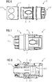
- Fig. 5 shows a spring element 6 which can be used for spring-loading the sleeve 3.1.
- said spring element 6 may be arranged at the outer surface of the connector main body 2, i.e. in a space between a wall portion of the connector main body 2 and said sleeve 3.1.
- the spring element 6 comprises a ring-shaped or circular-shaped or oval-shaped spring body 6.1 which can be deformed by a pressure applied to the spring body 6.1.
- the side portions of the spring body 6.1 may bend outwardly thereby reducing the height h of the spring element 6.
- the spring element 6 is made of a flexible material which is reversibly deformable. So, in case that the applied force is deactivated, the spring element 6 returns into its original shape thereby pushing the sleeve 3.1 into its initial position.
- the spring element 6 comprises a top portion 6.2 and a bottom portion 6.3, wherein the top portion 6.2 and/or the bottom portion 6.3 comprises a bar-shaped protrusion. Said bar-shaped protrusion provides a contact surface for the sleeve 3.1, respectively, the stop portion 2.3 provided at the connector main body 2. Thereby the application of force into the spring body 6.1 is improved.
- the spring element 6 may be concavely shaped in order to be able to adapt to the curved shape of the connector main body 2.
- the height of the spring body 6.1 (measured parallel to the central axis) may be greater than the width of the spring body 6.1 (measured perpendicular to the central axis).
- Fig. 6 shows the quick connector 1 in a partly disassembled state.
- a coupling ring 5 may be provided by means of which the snap hooks 4 and the spring elements 6 are interconnected. Said interconnection may be obtained at the lower side of the snap hooks 4 and the spring elements 6.
- the snap hooks 4 may be evenly distributed along the circumference and the spring elements 6 may be arranged between a pair of adjacent snap hooks 4.
- three snap hooks 4 and three spring elements 6 may be provided at the coupling ring 5. It is worth mentioning that also more or less snap hooks 4 / spring elements 6 can be used.
- the arrangement of snap hooks 4 / spring elements 6 at a common coupling ring 5 can be provided as an injection moulding component, i.e. the snap hooks 4, the spring elements 6 and the coupling ring 5 are integrally formed.
- a two-component-injection moulding process or multi-component injection moulding process can be used for manufacturing the assembly of snap hooks 4 / spring elements 6 at the common coupling ring 5.
- the snap hooks 4 comprise another material (e.g.
- the two-component-injection moulding process or multi-component injection moulding process may be chosen such that the plastic or polymer materials do not merge, in other words are not compatibel; but stay separated from each other and are interconnected by adhering forces of the plastic or polymer materials. It is worth mentioning that the assembly of snap hooks 4 / spring elements 6 at the common coupling ring 5 can also be manufactured using a single-component injection moulding process.
- the snap hooks 4 may even comprise multiple portions built by or made from different polymers. Thereby it may, for example, be possible to form an upper portion of the snap hooks 4 using a harder polymer and a middle portion using a polymer with a greater elasticity
- the coupling ring 5 comprising the snap hooks 4 and the spring elements 6 can be fixed at the connector main body 2 based on different techniques.
- the connector main body 2 may be adapted to provide an interlocking connection with the coupling ring 5.
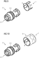
- the connector main body 2 may comprise one or more hooks or recesses adapted to interact with inversely formed portions at the coupling ring 5 in order to secure the coupling ring 5 at the connector main body 2 ( Fig. 9 ).
- the coupling ring 5 may be secured at the connector main body 2 based on a tight fit.
- a material shrinkage during a cooling down of the coupling ring 5 can be used for providing a tight fit of said coupling ring 5 at the connector main body 2.
- the coupling ring 5 can be secured at the connector main body 2 based on an over-moulded material portion 7.
- the over-moulded material portion 7 may secure the coupling ring 5 by form-fitted enclosing a contour of the connector main body 2.
- the connector main body 2 may comprise one or more protrusions (e.g. the stop portion 2.3 formed by a collar) at its outer surface which are arranged close to the coupling ring 5 and said coupling ring 5 is secured at the connector main body 2 by over-moulding said coupling ring 5 and said one or more protrusions.
- a two-component-injection moulding process or multi-component injection moulding process can be used.
- the injection moulding process may be chosen such that the plastic materials do not merge but stay separated from each other and are interconnected by adhering forces of the plastic materials.
- the connector main body 2 may comprise one or more recesses wherein during over-moulding the coupling ring 5, said recesses are filled with a plastic material. Thereby a positive connection between the connector main body 2 and the material providing the over-moulding of the coupling ring 5 is obtained.
- the spring elements 6 can be also included in the sleeve 3.1.
- the spring elements 6 may be provided within the sleeve 3.1 using a multi-component injection moulding process. Preferably, the spring elements 6 are directly injection-moulded at the inner surface of the sleeve 3.1.
- the sleeve 3.1 may comprise a contour or one or more recesses for providing a positive connection between the spring elements 6 and the sleeve 3.1.
Landscapes
- Engineering & Computer Science (AREA)
- General Engineering & Computer Science (AREA)
- Mechanical Engineering (AREA)
- Quick-Acting Or Multi-Walled Pipe Joints (AREA)
Priority Applications (1)
| Application Number | Priority Date | Filing Date | Title |
|---|---|---|---|
| PL18701699T PL3589876T3 (pl) | 2017-03-01 | 2018-01-18 | Szybkozłączka |
Applications Claiming Priority (2)
| Application Number | Priority Date | Filing Date | Title |
|---|---|---|---|
| DE102017001883 | 2017-03-01 | ||
| PCT/EP2018/051197 WO2018157994A1 (en) | 2017-03-01 | 2018-01-18 | Quick connector |
Publications (2)
| Publication Number | Publication Date |
|---|---|
| EP3589876A1 EP3589876A1 (en) | 2020-01-08 |
| EP3589876B1 true EP3589876B1 (en) | 2021-03-31 |
Family
ID=61054361
Family Applications (1)
| Application Number | Title | Priority Date | Filing Date |
|---|---|---|---|
| EP18701699.3A Active EP3589876B1 (en) | 2017-03-01 | 2018-01-18 | Quick connector |
Country Status (7)
| Country | Link |
|---|---|
| EP (1) | EP3589876B1 (pl) |
| CN (1) | CN110268187A (pl) |
| AU (1) | AU2018229386B2 (pl) |
| PL (1) | PL3589876T3 (pl) |
| RU (1) | RU2715948C1 (pl) |
| TW (1) | TWI744477B (pl) |
| WO (1) | WO2018157994A1 (pl) |
Families Citing this family (2)
| Publication number | Priority date | Publication date | Assignee | Title |
|---|---|---|---|---|
| DE102019129542A1 (de) | 2019-10-31 | 2021-05-06 | Norma Germany Gmbh | Schnellverbinder und Verbindungsanordnung mit verbesserter Dichtringarretierung |
| RU2735823C1 (ru) * | 2020-04-13 | 2020-11-09 | Миржалил Хамитович Усманов | Система для защиты пожарного и/или подготовленного квалифицированного персонала, противопожарного оборудования и техники от теплового излучения |
Family Cites Families (10)
| Publication number | Priority date | Publication date | Assignee | Title |
|---|---|---|---|---|
| FR1310713A (fr) * | 1961-10-20 | 1962-11-30 | Nord Aviation | Procédé et dispositif d'assemblage de corps tubulaires |
| IT8534836V0 (it) | 1985-04-02 | 1985-04-02 | Gf Srl | Raccordo ad innesto rapido per tubi flessibili in genere |
| DE19526884A1 (de) * | 1995-07-22 | 1997-01-23 | Gardena Kress & Kastner Gmbh | Hülse eines Gartengerätes, insbesondere Kupplungshülse einer Schlauch-Schnellkupplung, und Verfahren zur Herstellung |
| DE29719415U1 (de) * | 1997-10-31 | 1998-01-22 | Chen, Chien-Chih, Taichung | Schnellverbindungsstück |
| DE10355535B4 (de) * | 2003-11-27 | 2009-08-27 | A. Raymond Et Cie | Vorrichtung zum abgedichteten Verbinden von zwei Endstücken |
| US7731245B2 (en) * | 2006-10-06 | 2010-06-08 | Ti Group Automotive Systems, Llc | Quick connector coupling |
| DE102007020556B3 (de) * | 2007-05-02 | 2008-06-26 | Yuan Mei Corp. | Verbindungsteil für die Bewässerung |
| DE202009007897U1 (de) * | 2009-06-05 | 2009-10-01 | Wang, Hsin-Fa, Lu Kang | Wasserrohrmuffe |
| CN103282714A (zh) * | 2011-09-02 | 2013-09-04 | 沃泰有限公司 | 一键式配管连接装置 |
| US20130276932A1 (en) * | 2012-04-19 | 2013-10-24 | Composite Fluid Transfer LLC | System and method for reinforcing composite pipes |
-
2018
- 2018-01-18 PL PL18701699T patent/PL3589876T3/pl unknown
- 2018-01-18 EP EP18701699.3A patent/EP3589876B1/en active Active
- 2018-01-18 CN CN201880010388.XA patent/CN110268187A/zh active Pending
- 2018-01-18 WO PCT/EP2018/051197 patent/WO2018157994A1/en not_active Ceased
- 2018-01-18 AU AU2018229386A patent/AU2018229386B2/en not_active Ceased
- 2018-01-18 RU RU2019125452A patent/RU2715948C1/ru active
- 2018-02-08 TW TW107104549A patent/TWI744477B/zh active
Also Published As
| Publication number | Publication date |
|---|---|
| EP3589876A1 (en) | 2020-01-08 |
| TWI744477B (zh) | 2021-11-01 |
| TW201833472A (zh) | 2018-09-16 |
| AU2018229386B2 (en) | 2019-07-18 |
| WO2018157994A1 (en) | 2018-09-07 |
| CN110268187A (zh) | 2019-09-20 |
| AU2018229386A1 (en) | 2019-07-11 |
| PL3589876T3 (pl) | 2021-08-30 |
| RU2715948C1 (ru) | 2020-03-04 |
Similar Documents
| Publication | Publication Date | Title |
|---|---|---|
| AU2015355128B2 (en) | Needle shield puller cap assembly | |
| JP5395093B2 (ja) | マットをカーペットに固定するための留め具 | |
| CN102858197B (zh) | 母按扣 | |
| US4991882A (en) | Fluid-tight connector | |
| JP5765887B2 (ja) | シールアセンブリー・リテーナ付クイックコネクター | |
| JPH10305056A (ja) | 開口部カップリング、その部品、およびその製造方法 | |
| EP3589877B1 (en) | Quick connector | |
| JP2004518911A (ja) | 回転可能なクイックコネクタ | |
| EP2519766B1 (en) | A quick connector element | |
| EP3589876B1 (en) | Quick connector | |
| WO2009024787A1 (en) | Push-fit pipe fitting system | |
| KR102779978B1 (ko) | 두 개의 튜브형 물체를 연결하기 위한 장치 | |
| CN114555999A (zh) | 由塑料制成的快速连接器 | |
| KR101866356B1 (ko) | 파이프 연결 구조 | |
| GB2323418A (en) | Squeeze to release female conduit coupling member | |
| KR100856472B1 (ko) | 결합되는 2개의 유체 라인의 동축방향 단부 부분에 대한연결 시스템 | |
| US20100221062A1 (en) | Ball and Socket Connectors With Substructure | |
| CZ2001171A3 (cs) | Kulový kloub | |
| EP2188161B1 (en) | A windscreen wiper | |
| US12276362B2 (en) | Quick connector made of plastics | |
| JP6106112B2 (ja) | 連結体 | |
| GB2521825A (en) | Fitting |
Legal Events
| Date | Code | Title | Description |
|---|---|---|---|
| STAA | Information on the status of an ep patent application or granted ep patent |
Free format text: STATUS: UNKNOWN |
|
| STAA | Information on the status of an ep patent application or granted ep patent |
Free format text: STATUS: THE INTERNATIONAL PUBLICATION HAS BEEN MADE |
|
| PUAI | Public reference made under article 153(3) epc to a published international application that has entered the european phase |
Free format text: ORIGINAL CODE: 0009012 |
|
| STAA | Information on the status of an ep patent application or granted ep patent |
Free format text: STATUS: REQUEST FOR EXAMINATION WAS MADE |
|
| 17P | Request for examination filed |
Effective date: 20190619 |
|
| AK | Designated contracting states |
Kind code of ref document: A1 Designated state(s): AL AT BE BG CH CY CZ DE DK EE ES FI FR GB GR HR HU IE IS IT LI LT LU LV MC MK MT NL NO PL PT RO RS SE SI SK SM TR |
|
| AX | Request for extension of the european patent |
Extension state: BA ME |
|
| DAV | Request for validation of the european patent (deleted) | ||
| DAX | Request for extension of the european patent (deleted) | ||
| GRAJ | Information related to disapproval of communication of intention to grant by the applicant or resumption of examination proceedings by the epo deleted |
Free format text: ORIGINAL CODE: EPIDOSDIGR1 |
|
| GRAP | Despatch of communication of intention to grant a patent |
Free format text: ORIGINAL CODE: EPIDOSNIGR1 |
|
| GRAP | Despatch of communication of intention to grant a patent |
Free format text: ORIGINAL CODE: EPIDOSNIGR1 |
|
| STAA | Information on the status of an ep patent application or granted ep patent |
Free format text: STATUS: GRANT OF PATENT IS INTENDED |
|
| INTG | Intention to grant announced |
Effective date: 20210112 |
|
| GRAS | Grant fee paid |
Free format text: ORIGINAL CODE: EPIDOSNIGR3 |
|
| GRAA | (expected) grant |
Free format text: ORIGINAL CODE: 0009210 |
|
| STAA | Information on the status of an ep patent application or granted ep patent |
Free format text: STATUS: THE PATENT HAS BEEN GRANTED |
|
| AK | Designated contracting states |
Kind code of ref document: B1 Designated state(s): AL AT BE BG CH CY CZ DE DK EE ES FI FR GB GR HR HU IE IS IT LI LT LU LV MC MK MT NL NO PL PT RO RS SE SI SK SM TR |
|
| REG | Reference to a national code |
Ref country code: GB Ref legal event code: FG4D Ref country code: CH Ref legal event code: EP |
|
| REG | Reference to a national code |
Ref country code: DE Ref legal event code: R096 Ref document number: 602018014706 Country of ref document: DE Ref country code: AT Ref legal event code: REF Ref document number: 1377305 Country of ref document: AT Kind code of ref document: T Effective date: 20210415 |
|
| REG | Reference to a national code |
Ref country code: IE Ref legal event code: FG4D |
|
| REG | Reference to a national code |
Ref country code: NL Ref legal event code: FP |
|
| REG | Reference to a national code |
Ref country code: LT Ref legal event code: MG9D |
|
| PG25 | Lapsed in a contracting state [announced via postgrant information from national office to epo] |
Ref country code: NO Free format text: LAPSE BECAUSE OF FAILURE TO SUBMIT A TRANSLATION OF THE DESCRIPTION OR TO PAY THE FEE WITHIN THE PRESCRIBED TIME-LIMIT Effective date: 20210630 Ref country code: HR Free format text: LAPSE BECAUSE OF FAILURE TO SUBMIT A TRANSLATION OF THE DESCRIPTION OR TO PAY THE FEE WITHIN THE PRESCRIBED TIME-LIMIT Effective date: 20210331 Ref country code: FI Free format text: LAPSE BECAUSE OF FAILURE TO SUBMIT A TRANSLATION OF THE DESCRIPTION OR TO PAY THE FEE WITHIN THE PRESCRIBED TIME-LIMIT Effective date: 20210331 Ref country code: BG Free format text: LAPSE BECAUSE OF FAILURE TO SUBMIT A TRANSLATION OF THE DESCRIPTION OR TO PAY THE FEE WITHIN THE PRESCRIBED TIME-LIMIT Effective date: 20210630 |
|
| PG25 | Lapsed in a contracting state [announced via postgrant information from national office to epo] |
Ref country code: SE Free format text: LAPSE BECAUSE OF FAILURE TO SUBMIT A TRANSLATION OF THE DESCRIPTION OR TO PAY THE FEE WITHIN THE PRESCRIBED TIME-LIMIT Effective date: 20210331 Ref country code: RS Free format text: LAPSE BECAUSE OF FAILURE TO SUBMIT A TRANSLATION OF THE DESCRIPTION OR TO PAY THE FEE WITHIN THE PRESCRIBED TIME-LIMIT Effective date: 20210331 Ref country code: LV Free format text: LAPSE BECAUSE OF FAILURE TO SUBMIT A TRANSLATION OF THE DESCRIPTION OR TO PAY THE FEE WITHIN THE PRESCRIBED TIME-LIMIT Effective date: 20210331 |
|
| REG | Reference to a national code |
Ref country code: AT Ref legal event code: MK05 Ref document number: 1377305 Country of ref document: AT Kind code of ref document: T Effective date: 20210331 |
|
| PG25 | Lapsed in a contracting state [announced via postgrant information from national office to epo] |
Ref country code: AT Free format text: LAPSE BECAUSE OF FAILURE TO SUBMIT A TRANSLATION OF THE DESCRIPTION OR TO PAY THE FEE WITHIN THE PRESCRIBED TIME-LIMIT Effective date: 20210331 Ref country code: SM Free format text: LAPSE BECAUSE OF FAILURE TO SUBMIT A TRANSLATION OF THE DESCRIPTION OR TO PAY THE FEE WITHIN THE PRESCRIBED TIME-LIMIT Effective date: 20210331 Ref country code: LT Free format text: LAPSE BECAUSE OF FAILURE TO SUBMIT A TRANSLATION OF THE DESCRIPTION OR TO PAY THE FEE WITHIN THE PRESCRIBED TIME-LIMIT Effective date: 20210331 Ref country code: EE Free format text: LAPSE BECAUSE OF FAILURE TO SUBMIT A TRANSLATION OF THE DESCRIPTION OR TO PAY THE FEE WITHIN THE PRESCRIBED TIME-LIMIT Effective date: 20210331 Ref country code: CZ Free format text: LAPSE BECAUSE OF FAILURE TO SUBMIT A TRANSLATION OF THE DESCRIPTION OR TO PAY THE FEE WITHIN THE PRESCRIBED TIME-LIMIT Effective date: 20210331 |
|
| PG25 | Lapsed in a contracting state [announced via postgrant information from national office to epo] |
Ref country code: PT Free format text: LAPSE BECAUSE OF FAILURE TO SUBMIT A TRANSLATION OF THE DESCRIPTION OR TO PAY THE FEE WITHIN THE PRESCRIBED TIME-LIMIT Effective date: 20210802 Ref country code: RO Free format text: LAPSE BECAUSE OF FAILURE TO SUBMIT A TRANSLATION OF THE DESCRIPTION OR TO PAY THE FEE WITHIN THE PRESCRIBED TIME-LIMIT Effective date: 20210331 Ref country code: SK Free format text: LAPSE BECAUSE OF FAILURE TO SUBMIT A TRANSLATION OF THE DESCRIPTION OR TO PAY THE FEE WITHIN THE PRESCRIBED TIME-LIMIT Effective date: 20210331 Ref country code: IS Free format text: LAPSE BECAUSE OF FAILURE TO SUBMIT A TRANSLATION OF THE DESCRIPTION OR TO PAY THE FEE WITHIN THE PRESCRIBED TIME-LIMIT Effective date: 20210731 |
|
| REG | Reference to a national code |
Ref country code: DE Ref legal event code: R097 Ref document number: 602018014706 Country of ref document: DE |
|
| PG25 | Lapsed in a contracting state [announced via postgrant information from national office to epo] |
Ref country code: ES Free format text: LAPSE BECAUSE OF FAILURE TO SUBMIT A TRANSLATION OF THE DESCRIPTION OR TO PAY THE FEE WITHIN THE PRESCRIBED TIME-LIMIT Effective date: 20210331 Ref country code: AL Free format text: LAPSE BECAUSE OF FAILURE TO SUBMIT A TRANSLATION OF THE DESCRIPTION OR TO PAY THE FEE WITHIN THE PRESCRIBED TIME-LIMIT Effective date: 20210331 Ref country code: DK Free format text: LAPSE BECAUSE OF FAILURE TO SUBMIT A TRANSLATION OF THE DESCRIPTION OR TO PAY THE FEE WITHIN THE PRESCRIBED TIME-LIMIT Effective date: 20210331 |
|
| PLBE | No opposition filed within time limit |
Free format text: ORIGINAL CODE: 0009261 |
|
| STAA | Information on the status of an ep patent application or granted ep patent |
Free format text: STATUS: NO OPPOSITION FILED WITHIN TIME LIMIT |
|
| 26N | No opposition filed |
Effective date: 20220104 |
|
| PGFP | Annual fee paid to national office [announced via postgrant information from national office to epo] |
Ref country code: NL Payment date: 20211209 Year of fee payment: 5 |
|
| PG25 | Lapsed in a contracting state [announced via postgrant information from national office to epo] |
Ref country code: IS Free format text: LAPSE BECAUSE OF FAILURE TO SUBMIT A TRANSLATION OF THE DESCRIPTION OR TO PAY THE FEE WITHIN THE PRESCRIBED TIME-LIMIT Effective date: 20210731 |
|
| PGFP | Annual fee paid to national office [announced via postgrant information from national office to epo] |
Ref country code: IT Payment date: 20211209 Year of fee payment: 5 |
|
| PG25 | Lapsed in a contracting state [announced via postgrant information from national office to epo] |
Ref country code: MC Free format text: LAPSE BECAUSE OF FAILURE TO SUBMIT A TRANSLATION OF THE DESCRIPTION OR TO PAY THE FEE WITHIN THE PRESCRIBED TIME-LIMIT Effective date: 20210331 |
|
| REG | Reference to a national code |
Ref country code: CH Ref legal event code: PL |
|
| REG | Reference to a national code |
Ref country code: BE Ref legal event code: MM Effective date: 20220131 |
|
| PG25 | Lapsed in a contracting state [announced via postgrant information from national office to epo] |
Ref country code: LU Free format text: LAPSE BECAUSE OF NON-PAYMENT OF DUE FEES Effective date: 20220118 |
|
| PG25 | Lapsed in a contracting state [announced via postgrant information from national office to epo] |
Ref country code: BE Free format text: LAPSE BECAUSE OF NON-PAYMENT OF DUE FEES Effective date: 20220131 |
|
| PG25 | Lapsed in a contracting state [announced via postgrant information from national office to epo] |
Ref country code: LI Free format text: LAPSE BECAUSE OF NON-PAYMENT OF DUE FEES Effective date: 20220131 Ref country code: CH Free format text: LAPSE BECAUSE OF NON-PAYMENT OF DUE FEES Effective date: 20220131 |
|
| PG25 | Lapsed in a contracting state [announced via postgrant information from national office to epo] |
Ref country code: IE Free format text: LAPSE BECAUSE OF NON-PAYMENT OF DUE FEES Effective date: 20220118 |
|
| P01 | Opt-out of the competence of the unified patent court (upc) registered |
Effective date: 20230419 |
|
| REG | Reference to a national code |
Ref country code: NL Ref legal event code: MM Effective date: 20230201 |
|
| PG25 | Lapsed in a contracting state [announced via postgrant information from national office to epo] |
Ref country code: NL Free format text: LAPSE BECAUSE OF NON-PAYMENT OF DUE FEES Effective date: 20230201 |
|
| PG25 | Lapsed in a contracting state [announced via postgrant information from national office to epo] |
Ref country code: IT Free format text: LAPSE BECAUSE OF NON-PAYMENT OF DUE FEES Effective date: 20230118 |
|
| PG25 | Lapsed in a contracting state [announced via postgrant information from national office to epo] |
Ref country code: MK Free format text: LAPSE BECAUSE OF FAILURE TO SUBMIT A TRANSLATION OF THE DESCRIPTION OR TO PAY THE FEE WITHIN THE PRESCRIBED TIME-LIMIT Effective date: 20210331 Ref country code: CY Free format text: LAPSE BECAUSE OF FAILURE TO SUBMIT A TRANSLATION OF THE DESCRIPTION OR TO PAY THE FEE WITHIN THE PRESCRIBED TIME-LIMIT Effective date: 20210331 |
|
| PG25 | Lapsed in a contracting state [announced via postgrant information from national office to epo] |
Ref country code: HU Free format text: LAPSE BECAUSE OF FAILURE TO SUBMIT A TRANSLATION OF THE DESCRIPTION OR TO PAY THE FEE WITHIN THE PRESCRIBED TIME-LIMIT; INVALID AB INITIO Effective date: 20180118 |
|
| PG25 | Lapsed in a contracting state [announced via postgrant information from national office to epo] |
Ref country code: TR Free format text: LAPSE BECAUSE OF FAILURE TO SUBMIT A TRANSLATION OF THE DESCRIPTION OR TO PAY THE FEE WITHIN THE PRESCRIBED TIME-LIMIT Effective date: 20210331 |
|
| PG25 | Lapsed in a contracting state [announced via postgrant information from national office to epo] |
Ref country code: MT Free format text: LAPSE BECAUSE OF FAILURE TO SUBMIT A TRANSLATION OF THE DESCRIPTION OR TO PAY THE FEE WITHIN THE PRESCRIBED TIME-LIMIT Effective date: 20210331 |
|
| PG25 | Lapsed in a contracting state [announced via postgrant information from national office to epo] |
Ref country code: GR Free format text: LAPSE BECAUSE OF NON-PAYMENT OF DUE FEES Effective date: 20210331 |
|
| PG25 | Lapsed in a contracting state [announced via postgrant information from national office to epo] |
Ref country code: GR Free format text: LAPSE BECAUSE OF NON-PAYMENT OF DUE FEES Effective date: 20210331 |
|
| PGFP | Annual fee paid to national office [announced via postgrant information from national office to epo] |
Ref country code: DE Payment date: 20241216 Year of fee payment: 8 |
|
| PGFP | Annual fee paid to national office [announced via postgrant information from national office to epo] |
Ref country code: GB Payment date: 20251210 Year of fee payment: 9 |
|
| PGFP | Annual fee paid to national office [announced via postgrant information from national office to epo] |
Ref country code: FR Payment date: 20251210 Year of fee payment: 9 |
|
| PGFP | Annual fee paid to national office [announced via postgrant information from national office to epo] |
Ref country code: PL Payment date: 20251211 Year of fee payment: 9 |