EP3589850B1 - Federbelastete mutterplatte - Google Patents
Federbelastete mutterplatte Download PDFInfo
- Publication number
- EP3589850B1 EP3589850B1 EP18760498.8A EP18760498A EP3589850B1 EP 3589850 B1 EP3589850 B1 EP 3589850B1 EP 18760498 A EP18760498 A EP 18760498A EP 3589850 B1 EP3589850 B1 EP 3589850B1
- Authority
- EP
- European Patent Office
- Prior art keywords
- nut
- shell member
- plate assembly
- clip
- bias
- Prior art date
- Legal status (The legal status is an assumption and is not a legal conclusion. Google has not performed a legal analysis and makes no representation as to the accuracy of the status listed.)
- Active
Links
Images


Classifications
-
- F—MECHANICAL ENGINEERING; LIGHTING; HEATING; WEAPONS; BLASTING
- F16—ENGINEERING ELEMENTS AND UNITS; GENERAL MEASURES FOR PRODUCING AND MAINTAINING EFFECTIVE FUNCTIONING OF MACHINES OR INSTALLATIONS; THERMAL INSULATION IN GENERAL
- F16B—DEVICES FOR FASTENING OR SECURING CONSTRUCTIONAL ELEMENTS OR MACHINE PARTS TOGETHER, e.g. NAILS, BOLTS, CIRCLIPS, CLAMPS, CLIPS OR WEDGES; JOINTS OR JOINTING
- F16B37/00—Nuts or like thread-engaging members
- F16B37/04—Devices for fastening nuts to surfaces, e.g. sheets, plates
- F16B37/044—Nut cages
-
- F—MECHANICAL ENGINEERING; LIGHTING; HEATING; WEAPONS; BLASTING
- F16—ENGINEERING ELEMENTS AND UNITS; GENERAL MEASURES FOR PRODUCING AND MAINTAINING EFFECTIVE FUNCTIONING OF MACHINES OR INSTALLATIONS; THERMAL INSULATION IN GENERAL
- F16B—DEVICES FOR FASTENING OR SECURING CONSTRUCTIONAL ELEMENTS OR MACHINE PARTS TOGETHER, e.g. NAILS, BOLTS, CIRCLIPS, CLAMPS, CLIPS OR WEDGES; JOINTS OR JOINTING
- F16B2/00—Friction-grip releasable fastenings
- F16B2/20—Clips, i.e. with gripping action effected solely by the inherent resistance to deformation of the material of the fastening
- F16B2/22—Clips, i.e. with gripping action effected solely by the inherent resistance to deformation of the material of the fastening of resilient material, e.g. rubbery material
- F16B2/24—Clips, i.e. with gripping action effected solely by the inherent resistance to deformation of the material of the fastening of resilient material, e.g. rubbery material of metal
- F16B2/241—Clips, i.e. with gripping action effected solely by the inherent resistance to deformation of the material of the fastening of resilient material, e.g. rubbery material of metal of sheet metal
- F16B2/245—Clips, i.e. with gripping action effected solely by the inherent resistance to deformation of the material of the fastening of resilient material, e.g. rubbery material of metal of sheet metal external, i.e. with contracting action
-
- F—MECHANICAL ENGINEERING; LIGHTING; HEATING; WEAPONS; BLASTING
- F16—ENGINEERING ELEMENTS AND UNITS; GENERAL MEASURES FOR PRODUCING AND MAINTAINING EFFECTIVE FUNCTIONING OF MACHINES OR INSTALLATIONS; THERMAL INSULATION IN GENERAL
- F16B—DEVICES FOR FASTENING OR SECURING CONSTRUCTIONAL ELEMENTS OR MACHINE PARTS TOGETHER, e.g. NAILS, BOLTS, CIRCLIPS, CLAMPS, CLIPS OR WEDGES; JOINTS OR JOINTING
- F16B33/00—Features common to bolt and nut
- F16B33/002—Means for preventing rotation of screw-threaded elements
-
- F—MECHANICAL ENGINEERING; LIGHTING; HEATING; WEAPONS; BLASTING
- F16—ENGINEERING ELEMENTS AND UNITS; GENERAL MEASURES FOR PRODUCING AND MAINTAINING EFFECTIVE FUNCTIONING OF MACHINES OR INSTALLATIONS; THERMAL INSULATION IN GENERAL
- F16B—DEVICES FOR FASTENING OR SECURING CONSTRUCTIONAL ELEMENTS OR MACHINE PARTS TOGETHER, e.g. NAILS, BOLTS, CIRCLIPS, CLAMPS, CLIPS OR WEDGES; JOINTS OR JOINTING
- F16B37/00—Nuts or like thread-engaging members
- F16B37/04—Devices for fastening nuts to surfaces, e.g. sheets, plates
- F16B37/06—Devices for fastening nuts to surfaces, e.g. sheets, plates by means of welding or riveting
- F16B37/062—Devices for fastening nuts to surfaces, e.g. sheets, plates by means of welding or riveting by means of riveting
- F16B37/064—Devices for fastening nuts to surfaces, e.g. sheets, plates by means of welding or riveting by means of riveting with the use of separate rivets
Definitions
- the field of the disclosure relates generally to nut plates, and more specifically to nut plates including a spring-loaded nut.
- At least some known floating nut plates include a base or bottom plate with an opening and support a nut or similar fastener element that is captured on the base by a retainer or cage component.
- Such nut plates facilitate holding components, for example panels, together when a fastener is threadably engaged with the nut plate and tightened, while still enabling some movement between the components.
- the nut receives a fastener, such as a bolt, screw, or other threaded component element passed through an opening in the components and threaded into the nut.
- the opening in the component may be sized to enable the nut and fastener to move laterally to accommodate some movement between the fastened components.
- At least some known floating nut plates may be used in the aerospace industry.
- the types and numbers of fasteners for a panel assembly can be significant.
- Some panel fasteners for a particular panel assembly may have different lengths, while otherwise looking similar to other panel fasteners.
- a user may typically place all the panel fasteners in a separate location to keep from misplacing the fasteners.
- the user may inadvertently use an incorrect length fastener for a particular panel fastener location. This can lead to an improperly attached panel assembly.
- US 3,160,187 A discloses a fastening device including a stud and a receptacle for engaging with the stud when inserted therein.
- the receptacle includes a first piece including a hat-shaped casing and a lateral directed flange.
- the second piece of the receptacle includes a socket member located in the casing.
- US 2,737,222 A discloses a panel fastener including a socket and a stud for assembling with panels.
- the socket includes a hollow sheet metal housing. The housing has an open end having a mounting flange and an opposite end which is substantially closed.
- US 2009/129885 A1 describes a floating nut plate including complementary surfaces limiting movement of a retainer toward or away from side walls of a receiver, such as wherein a nut element is positioned between the retainer and the receiver.
- EP 2 352 927 A1 describes a fastening device for providing a wall part of a carrying beam, such as a chassis beam, with an internal screw thread in order to fasten-in a bolt.
- the nut plate assembly includes a plate member including an aperture defined therethrough.
- the nut plate assembly also includes a shell member having a first end joined to the plate member and a second end opposite the first end.
- the nut plate assembly further includes a bias member disposed within the shell member, and a nut including a body and a shoulder portion configured to receive a portion of the bias member, said body including an outer surface defining a first diameter and said shoulder portion defining a second diameter.
- the nut is disposed within the shell member and moveable between a first position proximate the shell member first end and a second position proximate the shell member second end.
- the bias member comprises a coil-spring positioned to bias the nut toward the second position.
- the second diameter defined by said shoulder portion is smaller than the first diameter defined by said outer surface to allow said bias member to extend along said shoulder portion and provide an axial force to said body.
- a fastener assembly includes a nut plate assembly adapted for mounting to a mounting structure.
- the fastener assembly also includes a fastener configured to mount in an aperture formed in a panel member. The fastener is threadably engageable with the nut for coupling the panel member to the mounting structure.
- a method of assembling a nut plate assembly includes positioning a bias member within a shell member.
- the shell member has a first end joined to a plate member and a second end opposite the first end.
- the plate member includes an aperture defined therethrough.
- the method also includes positioning a nut within the shell member.
- the nut includes a body and a shoulder portion configured to receive a portion of the bias member, said body including an outer surface defining a first diameter and said shoulder portion defining a second diameter.
- the nut is moveable between a first position proximate the shell member first end and a second position proximate the shell member second end.
- the bias member comprises a coil-spring positioned to bias the nut toward the second position.
- the second diameter defined by said shoulder portion is smaller than the first diameter defined by said outer surface to allow said bias member to extend along said shoulder portion and provide an axial force to said body.
- the method further includes coupling a retention member to at least one of the shell member and the plate member to retain the nut within the shell member, wherein the retention member includes a clip configured to engage the shell member and the nut.
- Approximating language may be applied to modify any quantitative representation that could permissibly vary without resulting in a change in the basic function to which it is related. Accordingly, a value modified by a term or terms such as "about,” “approximately,” and “substantially” are not to be limited to the precise value specified. In at least some instances, the approximating language may correspond to the precision of an instrument for measuring the value.
- range limitations may be combined and/or interchanged; such ranges are identified and include all the sub-ranges contained therein unless context or language indicates otherwise.
- the pre-load force on floating nut 106 may be adjusted by varying the wire diameter and spring length of bias member 108.
- the wire diameter and spring length of bias member 108 is selected to provide the necessary pre-load required for operation of nut plate assembly 100, while maintaining bias member 108 in an axial resiliency range.
- Bore 142 includes a female threaded portion 152 extending between tapered portion 146 and counter bored portion 150 for threadably coupling to a fastener during use of nut plate assembly 100.
- counter bored portion 150 functions as a way to control a length of female threaded portion 152 to facilitate maintaining a thread engagement length to about one times the thread diameter, while allowing the fastener to extend through female threaded portion 152.
- counter bored portion 150 facilitates fabricating cylindrical body 140 with a shoulder portion 158 having a length sufficient to prevent over-stressing and/or damaging bias member 108 while maintaining a thread engagement length to about one times the thread diameter, as described further herein.
- Floating nut 106 includes a hole 154 defined in an outer surface 156 of cylindrical body 140.
- hole 154 is formed in outer surface 156 substantially perpendicular to centerline "C" of cylindrical body 140.
- hole 154 extends a predetermined depth into cylindrical body 140, but does not extend through to bore 142.
- hole 154 may extend any depth into cylindrical body 140, including, for example, entirely through cylindrical body 140.
- Hole 154 is sized and shaped to receive anti-rotation pin 138 therein.
- hole 154 is sized to form an interference fit with anti-rotation pin 138.
- interference fit means a value of tightness between anti-rotation pin 138 and hole 154, i.e., an amount of radial clearance between the components.
- a negative amount of clearance is commonly referred to as a press fit, where the magnitude of interference determines whether the fit is a light interference fit or interference fit.
- a small amount of positive clearance is referred to as a loose or sliding fit.
- anti-rotation pin 138 may be coupled to cylindrical body 140 using any suitable fastening technique that enables nut plate assembly 100 to function as described herein.
- an upper portion of anti-rotation pin 138 extends through longitudinal slot 134 to facilitate preventing rotation of floating nut 106 while enabling axial movement during use of nut plate assembly 100.
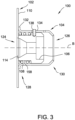
- floating nut 106 includes shoulder portion 158 extending from first end 144 axially along cylindrical body 140 a predetermined distance 160 that facilitates preventing over-stressing and/or damaging bias member 108 when bias member 108 is compressed, while enabling bias member 108 to urge cylindrical body 140 away from plate member 102 when extended.
- Shoulder portion 158 has a diameter that is smaller than the diameter of outer surface 156 of cylindrical body 140.
- shoulder portion 158 has a diameter configured to enable bias member 108 to slide onto shoulder portion 158, as shown in FIG. 3 .
- Shoulder portion 158 enables bias member 108 to apply an axial force to cylindrical body 140 to urge cylindrical body 140 away from plate member 102, as described herein.
- floating nut 106 is placed into shell member 104. Hole 154 of floating nut 106 is aligned with longitudinal slot 134. Anti-rotation pin 138 is press fit into hole 154 such that an end of anti-rotation pin 138 extends through longitudinal slot 134. Bias member 108 is placed about shoulder portion 158 of floating nut 106. First opening 124 of shell member 104 is substantially aligned with aperture 114 of plate member 102. Shell member 104 is pressed against plate member 102, thereby compressing bias member 108 within shell member 104. Retention tabs 112 are then curled or bent over flange 132 of shell member 104 to axially retain shell member 104 to plate member 102. As shown in FIG.
- semi-circular cutouts 118 have a curvature that is greater than a diameter of cylindrical wall 122 of shell member 104, but less than a diameter of flange 132. This facilitates enabling shell member 104 to move a small amount along wall portion 110, while remaining in face to face contact with wall portion 110.
- a fastener (not shown in FIG. 1 ) may be aligned with floating nut 106, which is retained in shell member 104, even if there is minor misalignment with the fastener and aperture 114 of plate member 102.
- nut plate assembly 100 is configured to retain both floating nut 106 and bias member 108 within shell member 104, which allows for nut plate assembly 100 to be used as an inseparable assembly.
- nut plate assembly 100 requires no access from the nut side of nut plate assembly 100, which is advantageous for use with panels and other structure where access to both sides of nut plate assembly 100 is limited.
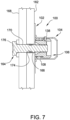
- FIG. 7 is a cross-sectional view of installed nut plate assembly 100 coupled to mounting structure 162, including a captive fastener 164.
- nut plate assembly 100 is coupled to mounting structure 162 by, for example, and without limitation, adhesive bonding.
- Mounting structure 162 includes an aperture 166 defined therethrough and sized to receive at least a portion of fastener 164.
- Fastener 164 also extends through a panel 168 via aperture 170.
- aperture 170 has a diameter smaller than the diameter of aperture 166. This facilitates capturing fastener 164 in panel 168 by a locking mechanism 172.
- fastener 164 includes locking mechanism 172.
- locking mechanism 172 is a lock ring.
- locking mechanism 172 includes, for example, and without limitation, a retaining ring, an E-clip, a spring plunger, and/or any mechanism configured to facilitate capturing fastener 164 in panel 168.
- locking mechanism 172 is coupled to a groove 174 formed in fastener 164 a predetermined distance from a head 176 of fastener 164.
- groove 174 may be formed at a distance that enables panel 168 to be positioned between head 176 and locking mechanism 172, thereby facilitating capturing fastener 164 in panel 168.
- fastener 164 is inserted through aperture 170, locking mechanism 172 collapses into groove 174. After locking mechanism 172 passes through aperture 170, it expands radially to its original diameter to prevent fastener 164 from being pulled back through panel 168.
- fastener 164 is a panel bolt having a hexagonal head 176.
- fastener 164 is any type of fastener having head 176 taking any shape or form, including for example, and without limitation, a spline head, a flat head, a socket cap head, and a pan head.
- fastener 164 is a locking fastener, including one or more components configured to lock fastener 164 against rotation relative to panel 168.
- Panel 168, with fastener 164, is introduced to mounting structure 162 with nut plate assembly 100 for assembly.
- Fastener 164 is aligned with floating nut 106 and panel 168 is pushed toward mounting structure 162 until fastener 164 contacts female threaded portion 152 of floating nut 106.
- Fastener 164 is threadably engaged with floating nut 106.
- Floating nut 106 is drawn toward fastener 164 and compresses bias member 108.
- the spring rate of bias member 108 can be adjusted by increasing or decreasing the wire diameter and/or the length of bias member 108, as described herein. Further, in some embodiments, the force of bias member 108 against floating nut 106 may be adjusted by increasing or decreasing an amount of torque applied to fastener 164.
- bias member 108 is compressed and increases the force against floating nut 106 until floating nut 106 is seated against wall portion 110.
- bias member 108 is decompressed and decreases the force against floating nut 106 until floating nut 106 is biased against second end 130 of shell member 104.
- FIG. 8 is a cross-sectional view of another embodiment of installed nut plate assembly 100 coupled to mounting structure 162, and including captive fastener 164.
- nut plate assembly 100 is mechanically coupled to mounting structure 162 by fasteners 178.
- fasteners 178 include, for example, and without limitation, nut and bolt combinations, sheet metal fasteners, rivets, and the like.
- Retention tabs 212 prior to coupling shell member 204 to plate member 202, lie in a plane of wall portion 210. In another embodiment, retention tabs 212 may be folded or bent perpendicular to wall portion 210. During assembly of nut plate assembly 200, retention tabs 212 are curled or bent along a respective edge 216 of plate member 202 to facilitate coupling shell member 204 to plate member 202. Each retention tab 212 has a semi-circular cutout 218 defined on an edge 220 of each retention tab 212.
- shell member 204 includes a substantially cylindrical wall 222 that defines a first opening 224 at a first end 228 and a second opening 226 at a second end 230 of shell member 204.
- First opening 224 and second opening 226 are generally concentric with each other.
- Shell member 204 includes a flange 232 formed at first end 228.
- cylindrical wall 222 tapers radially inward, e.g., by a swaging process, to facilitate retaining floating nut 206 within shell member 204 when shell member 204 is coupled to plate member 202.
- Floating nut 206 includes a hole 254 defined in an outer surface 256 of cylindrical body 240.
- hole 254 is formed in outer surface 256 substantially perpendicular to centerline "F" of cylindrical body 240.
- hole 254 extends a predetermined depth into cylindrical body 240, but does not extend through to bore 242.
- hole 254 may extend any depth into cylindrical body 240, including, for example, entirely through cylindrical body 240.
- Hole 254 is sized and shaped to receive anti-rotation pin 238 therein.
- hole 254 is sized to form an interference fit with anti-rotation pin 238.
- anti-rotation pin 238 may be coupled to cylindrical body 240 using any suitable fastening technique that enables nut plate assembly 200 to function as described herein.
- an upper portion of anti-rotation pin 238 extends through longitudinal slot 234 to facilitate preventing rotation of floating nut 206 while enabling axial movement during use of nut plate assembly 200.
- floating nut 206 includes shoulder portion 258 extending from second end 248 axially along cylindrical body 240 a predetermined distance 260 that facilitates preventing over-stressing and/or damaging bias member 208 when bias member 208 is compressed, while enabling bias member 208 to urge cylindrical body 240 toward plate member 202 when extended.
- Shoulder portion 258 has a diameter that is smaller than the diameter of outer surface 256 of cylindrical body 240.
- shoulder portion 258 has a diameter configured to enable bias member 208 to slide onto shoulder portion 258, as shown in FIG. 10 .
- Shoulder portion 258 enables bias member 208 to apply an axial force to cylindrical body 240 to urge cylindrical body 240 toward plate member 202, as described herein.
- Nut plate assembly 200 is assembled substantially similar to nut plate assembly 100 described above.
- bias member 208 is placed into shell member 204.
- Floating nut 206 is placed into shell member 204 such that bias member 208 seats about shoulder portion 258 of floating nut 206.
- Hole 254 of floating nut 206 is aligned with longitudinal slot 234.
- Anti-rotation pin 238 is press fit into hole 254 such that an end of anti-rotation pin 238 extends through longitudinal slot 234.
- First opening 224 of shell member 204 is substantially aligned with aperture 214 of plate member 202.
- Shell member 204 is pressed against plate member 202, thereby compressing bias member 208 within shell member 204.
- Retention tabs 212 are then curled or bent over flange 232 of shell member 204 to axially retain shell member 204 to plate member 202.
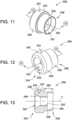
- FIG. 15 is a perspective view of a spring-loaded nut plate assembly 300.
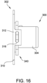
- FIG. 16 is a side view of nut plate assembly 300.
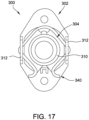
- FIG. 17 is an end view of nut plate assembly 300.
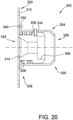
- nut plate assembly 300 is similar to nut plate assembly 100 (shown in FIG. 1 ) and nut plate assembly 200 (shown in FIG. 10 ) and includes a plate member 302, a shell member 304, a floating nut 306, and a bias member 308 (shown in FIG. 20 ).
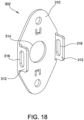
- Plate member 302 includes a wall portion 310 and a plurality of retention tabs 312 integrally formed with wall portion 310.
- Wall portion 310 includes an aperture 314 defined therethrough for receiving a fastener (not shown in FIGs. 15-17 ).
- Retention tabs 312 extend from wall portion 310 and define openings 316.
- nut plate assembly 300 includes any plate member 302 that enables nut plate assembly 300 to function as described herein.
- shell member 304 includes a substantially cylindrical wall 322 that defines a first opening 324 (shown in FIG. 20 ) at a first end 328 of shell member 304 and a second opening 326 at a second end 330 of shell member 304.
- Shell member 304 includes a flange 332 formed at first end 328.
- cylindrical wall 322 tapers radially inward, e.g., by a swaging process, to facilitate retaining floating nut 306 within shell member 304 when shell member 304 is coupled to plate member 302.
- floating nut 306 is disposed within shell member 304 and is moveable relative to cylindrical wall 322.
- floating nut 306 is moveable along a central axis of shell member 304 between a first position and a second position. In the first position, floating nut 306 is proximate first end 328. In the second position, floating nut 306 is proximate second end 330.
- floating nut 306 is moveable in any manner that enables nut plate assembly 300 to operate as described herein.
- FIG. 18 is a perspective view of plate member 302 of nut plate assembly 300 (shown in FIG. 15 ).
- FIG. 19 is a top view of retention member 340 of nut plate assembly 300 (shown in FIG. 15 ).
- Clip 342 of retention member 340 has a curved shape and is configured to extend around shell member 304 (shown in FIG. 15 ). In particular, clip 342 forms a loop. Ends 346 of clip 342 are adjacent each other and define a gap 348 therebetween.
- clip 342 includes elbows 344 which are configured to extend into openings 316 on opposite sides of plate member 302. In the exemplary embodiments, openings 316 are elongated slots that are configured to receive elbows 344.
- bias member 308 may be any type of bias or force provider that enables nut plate assembly 300 to function as described herein.
- the pre-load force on floating nut 306 may be adjusted by varying the wire diameter and spring length of bias member 308.
- the wire diameter and spring length of bias member 308 is selected to provide the necessary pre-load required for operation of nut plate assembly 300, while maintaining bias member 308 in an axial resiliency range.
- nut plate assembly 300 includes any bias member 308 that enables nut plate assembly 300 to function as described herein.
- bias member 308 is positioned within shell member 304 and between floating nut 306 and second end 330.
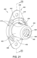
- FIG. 21 is a perspective view of a spring-loaded nut plate assembly 400.
- FIG. 22 is a side view of nut plate assembly 400.
- FIG. 23 is an end view of nut plate assembly 400.
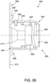
- nut plate assembly 400 is similar to nut plate assembly 300 (shown in FIG. 15 ) and includes a plate member 402, a shell member 404, a floating nut 406, and a bias member 408 (shown in FIG. 26 ).
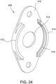
- Plate member 402 includes a wall portion 410 and a plurality of retention tabs 412 integrally formed with wall portion 410.
- Wall portion 410 includes an aperture 414 defined therethrough for receiving a fastener (not shown in FIGs. 21-23 ).
- Retention tabs 412 extend from wall portion 410 and define channels 416.
- nut plate assembly 400 includes any plate member 402 that enables nut plate assembly 400 to function as described herein.
- shell member 404 includes a substantially cylindrical wall 422 that defines a first opening 424 (shown in FIG. 26 ) at a first end 428 of shell member 404 and a second opening 426 at a second end 430 of shell member 404.
- Shell member 404 includes a flange 432 formed at first end 428.
- cylindrical wall 422 tapers radially inward, e.g., by a swaging process, to facilitate retaining floating nut 406 within shell member 404 when shell member 404 is coupled to plate member 402.
- floating nut 406 is disposed within shell member 404 and is moveable relative to cylindrical wall 422.
- floating nut 406 is moveable along a central axis of shell member 404 between a first position and a second position. In the first position, floating nut 406 is proximate first end 428. In the second position, floating nut 406 is proximate second end 430.
- floating nut 406 is moveable in any manner that enables nut plate assembly 400 to operate as described herein.
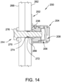
- nut plate assembly 400 includes a retention member 440 coupled to plate member 402 and shell member 404.
- retention member 440 includes a clip 442 configured to extend at least partially around shell member 404 and extend over flange 432.
- Clip 442 is configured to engage retention tabs 412 when clip 442 is positioned around shell member 404.
- retention member 440 and retention tabs 412 couple shell member 404 to plate member 402 and axially retain shell member 404 with respect to plate member 402.
- First end 428 of shell member 404 contacts plate member 402 and flange 432 is positioned between clip 442 and wall portion 410 when retention member 440 is coupled to plate member 402 and shell member 404.
- FIG. 24 is a perspective view of plate member 402 of nut plate assembly 400 (shown in FIG. 21 ).
- FIG. 25 is a top view of retention member 440 of nut plate assembly 400 (shown in FIG. 21 ).
- Clip 442 of retention member 440 has a curved shape and is configured to extend around shell member 404 (shown in FIG. 21 ).
- clip 442 is a semicircle and includes ends 446 spaced circumferentially apart to define a gap 448 therebetween.
- clip 442 is sized and shaped to extend through channels 416 defined by retention tabs 412.
- retention tabs 412 extend along at least a portion of the edge of wall portion 410 and are configured to extend over clip 442 when clip 442 extends through channels 416.
- retention member 440 engages plate member 402 in any manner that enables nut plate assembly (shown in FIG. 21 ) to operate as described herein.
- retention member 440 includes a channel 416 that receives plate member 402.
- clip 442 is moved between the first position and the second position by pressing on ends 446 of clip 442 to decrease the width of gap 448 and the diameter of clip 442.
- clip 442 does not extend through channels 416 in retention tabs 412 and allows removal of retention member 440 from nut plate assembly 400 (shown in FIG. 21 ).
- shell member 404 (shown in FIG. 21 ) is free from plate member 402.
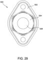
- FIG. 27 is a perspective view of a spring-loaded nut plate assembly 500.
- FIG. 28 is a front end view of nut plate assembly 500.
- FIG. 29 is a second end view of nut plate assembly 500.
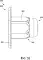
- FIG. 30 is an end view of nut plate assembly 500.
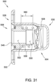
- FIG. 31 is a cross-sectional view of nut plate assembly 500, taken about line 31-31 shown in FIG. 28 .
- nut plate assembly 500 is similar to nut plate assembly 100 (shown in FIG. 1 ) and includes a plate member 502, a shell member 504, a floating nut 506, and a bias member 508 (shown in FIG. 31 ).
- plate member 502 and shell member 504 are integrally formed as a single piece.
- Plate member 502 includes a wall portion 510.
- Wall portion 510 includes an aperture 514 defined therethrough for receiving a fastener (not shown in FIGs. 27-31 ).
- aperture 514 is sized and shaped to allow floating nut 506 to be positioned therethrough.
- aperture 514 is a hexagon.
- nut plate assembly 500 includes any plate member 502 that enables nut plate assembly 500 to operate as described herein.
- shell member 504 includes a wall 522 that extends around and along a central axis 523 of nut plate assembly 500.
- Wall 522 defines a first opening 524 at a first end 528 of shell member 504 and a second opening 526 at a second end 530 of shell member 504.
- First opening 524 and second opening 526 are generally concentric with each other.
- shell member 504 is joined to wall portion 510 of plate member 502.
- a curved or angled edge 525 extends between aperture 514 and first opening 524 to facilitate positioning clip 566 through aperture 514.
- wall 522 tapers radially inward to facilitate retaining floating nut 506 within shell member 504.
- floating nut 506 is disposed within shell member 504 and is moveable along central axis 523.
- floating nut 506 is moveable along central axis 523 of shell member 504 between a first position and a second position. In the first position, floating nut 506 is proximate first end 528. In the second position, floating nut 506 is proximate second end 530.
- floating nut 506 has radial float about central axis 523 within wall 522. In alternative embodiments, floating nut 506 is moveable in any manner that enables nut plate assembly 500 to operate as described herein.
- bias member 508 is positioned within shell member 504 between floating nut 506 and second end 530 of shell member 504. As such, bias member 508 facilitates biasing floating nut 506 axially toward plate member 502 and towards the first position. During use of nut plate assembly 500, bias member 508 facilitates pushing the attaching structure apart as a fastener (not shown in FIGs. 27 and 28 ) is coupled with floating nut 506. Bias member 508 may function as a damping element. In the exemplary embodiment, bias member 508 is a compression spring. Alternatively, bias member 508 may be any type of bias or force provider that enables nut plate assembly 500 to function as described herein.
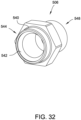
- FIG. 32 is a perspective view of floating nut 506 for use with nut plate assembly 500 (shown in FIG. 27 ).
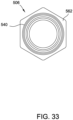
- FIG. 33 is an end view of floating nut 506.
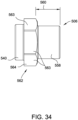
- FIG. 34 is a side view of floating nut 506.
- floating nut 506 has a body 540 that defines a bore 542 therethrough.
- bore 542 includes a tapered portion 546 configured to facilitate aligning a fastener (not shown in FIGs. 32-33 ) with body 540.
- bore 542 includes a counter bored portion 550.
- Bore 542 includes a female threaded portion 552 extending between tapered portion 546 and counter bored portion 550 for threadably coupling to a fastener during use of nut plate assembly 500.
- the cross-sectional shape of floating nut 506 corresponds to the cross-sectional shape of shell member 504 (shown in FIGS. 27-30 ).
- outer surface 564 of flange 562 is defined by six planar sides 563 forming a hexagonal cross-sectional shape.
- floating nut 506 includes any flange 562 that enables floating nut 506 to operate as described herein.
- clip 566 is positioned within shell member 504 proximate first end 528 of shell member 504 such that floating nut 506 is trapped between second end 530 of shell member 504 and clip 566.
- Clip 566 is positionable between a first position in which clip 566 fits through aperture 514 and a second position in which clip 566 is retained within shell member 504. Gap 568 facilitates clip 566 moving between the first position and the second position.
- clip 566 In the first position, clip 566 is positionable through aperture 514 into the interior cavity of shell member 504. For example, in the first position, clip 566 is deformed such that a width of clip 566 is less than the width of aperture 514.
- clip 566 In the second position, clip 566 has a diameter that is larger than a width of aperture 514.
- Clip 566 is moved from the second position to the first position by pressing clip 566 with an inward radial force.
- Clip 566 is resilient and returns to the second position when the inward radial force is removed.
- Clip 566 includes a notch 569 configured to facilitate moving clip 566 between the second position and the first position when clip 566 is positioned within shell member 504.
- shell member 504 has a plurality of grooves 570 spaced about central axis 523. Each groove 570 receives a portion of clip 566 when clip 566 is in the first position within shell member 504. Grooves 570 act as engagement features that engage clip 566 and resist axial movement of clip 566 when clip 566 is within shell member 504 in the first position. As a result, clip 566 and shell member 504 resist removal of floating nut 506 when floating nut 506 and clip 566 are positioned within shell member 504. Shell member 504 retains clip 566 therein and clip 566 contacts flange 562 of floating nut 506 to inhibit removal of floating nut 506 through aperture 514.
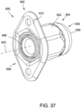
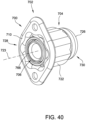
- FIG. 37 is a perspective view of another spring-loaded nut plate assembly 600.
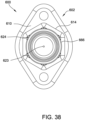
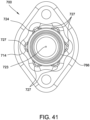
- FIG. 38 is an end view of nut plate assembly 600.
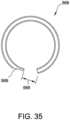
- FIG. 39 is a perspective view of a clip 666 for use with nut plate assembly 600.
- nut plate assembly 600 is similar to nut plate assembly 100 (shown in FIG. 1 ) and includes a plate member 602, a shell member 604, a floating nut 606, and a bias member (not shown in FIGs. 37-39 ).
- Plate member 602 includes a wall portion 610 integrally formed with shell member 604.
- Wall portion 610 includes an aperture 614 defined therethrough for receiving a fastener (not shown in FIGs. 27-31 ).
- aperture 614 is sized and shaped to allow floating nut 606 to be positioned therethrough.
- nut plate assembly 600 includes any plate member 602 that enables nut plate assembly 600 to operate as described herein.
- shell member 604 engages floating nut 606 to inhibit rotation of floating nut 606 when floating nut 606 is positioned within shell member 604.
- shell member 604 and floating nut 606 are hexagons.
- shell member 604 and floating nut 606 are any shapes that enable nut plate assembly 600 to operate as described herein.
- shell member 604 and/or floating nut 606 includes, without limitation, a triangle, a rectangle, a trapezoid, a pentagon, a hexagon, a heptagon, an octagon, a nonagon, a decagon, a dodecagon, and a star.
- at least one side of shell member 604 and/or floating nut 606 is curved.
- nut plate assembly 600 includes a clip, more broadly a retention member, 666.
- Clip 666 is configured to engage shell member 604 and floating nut 606 (shown in FIGS. 32-34 ) to retain floating nut 606 within shell member 604.
- clip 666 is circular and is arranged to extend around central axis 623 when clip 666 is positioned in shell member 604.
- nut plate assembly 600 includes any clip 666 that enables nut plate assembly 600 to operate as described herein.
- shell member 704 includes a wall 722 that extends around and along a central axis 723 of nut plate assembly 700.
- Wall 722 defines a first opening 724 at a first end 728 of shell member 704 and a second opening 726 at a second end 730 of shell member 704.
- First opening 724 and second opening 726 are generally concentric with each other.
- shell member 704 is joined to wall portion 710 of plate member 702.
- wall 722 tapers radially inward to facilitate retaining floating nut 706 within shell member 704.
- Wall 722 extends continuously from first end 728 to second end 730 and is free of openings other than first opening 724 and second opening 726. Accordingly, shell member 704 and plate member 702 inhibit the entrapment of debris and containments during use of nut plate assembly 700.
- nut plate assembly 700 includes any shell member 704 that enables nut plate assembly 700 to operate as described herein.
- a cross-sectional shape of shell member 704 is defined by wall 722.
- the cross-sectional shape of shell member 704 is taken along a plane perpendicular to central axis 723 and is configured to correspond to the cross-sectional shape of floating nut 706.
- Floating nut 706 includes a plurality of projections 725 that are received in cavities 727 in shell member 704. Accordingly, wall 722 of shell member 704 engages floating nut 706 to inhibit rotation of floating nut 706 when floating nut 706 is positioned within shell member 704.
- shell member 704 and floating nut 706 are any shapes that enable nut plate assembly 700 to operate as described herein.
- shell member 704 and/or floating nut 706 includes, without limitation, a triangle, a rectangle, a trapezoid, a pentagon, a hexagon, a heptagon, an octagon, a nonagon, a decagon, a dodecagon, and a star.
- at least one side of shell member 704 and/or floating nut 706 is curved.
- nut plate assembly 700 includes clip, more broadly a retention member, 766.
- Clip 766 is configured to engage shell member 704 and floating nut 706 to retain floating nut 706 within shell member 704.
- nut plate assembly 700 includes any clip 766 that enables nut plate assembly 700 to operate as described herein.
- clip 766 is positioned within shell member 704 proximate first end 728 of shell member 704 such that floating nut 706 is trapped between second end 730 of shell member 704 and clip 766. Accordingly, shell member 704 and clip 766 resist axial movement of clip 766 when clip 766 is within shell member 704 and in the second position. As a result, clip 766 and shell member 704 resist removal of floating nut 706 when floating nut 706 and clip 766 are positioned within shell member 704. In altemative embodiments, clip 766 engages plate member 702 and/or shell member 704 in any manner that enables nut plate assembly 700 to operate as described herein.
- FIG. 42 is a perspective view of floating nut 706 for use with nut plate assembly 700.
- FIG. 43 is a front view of floating nut 706.
- floating nut 706 has a body 740 that defines a bore 742 therethrough. Bore 742 extends from a first end 746 of floating nut 706 to a second end 748 of floating nut 706.
- Floating nut 706 includes a shoulder portion 758 and a flange 762. Shoulder portion 758 extends from second end 748 axially along body 740 to flange 762. Shoulder portion 758 enables a bias member (not shown in FIGs. 37-39 ) to apply an axial force to body 740 to urge body 740 toward plate member 702.
- outer surface 764 of flange 762 is defined by six projections 725 forming a star cross-sectional shape.
- the shape of flange 762 provides increased resistance to torque forces on floating nut 706 in comparison to other flanges such as flange 562 (shown in FIG. 33 ).
- floating nut 706 includes any flange 762 that enables floating nut 706 to operate as described herein.
Landscapes
- Engineering & Computer Science (AREA)
- General Engineering & Computer Science (AREA)
- Mechanical Engineering (AREA)
- Connection Of Plates (AREA)
Claims (15)
- Mutter-Plattenanordnung (100) umfassend:ein Plattenelement (102) umfassend eine hier durch definierte Öffnung (114);ein Schalenelement (104) mit einem ersten Ende (128), das mit dem Plattenelement verbunden ist, und einem zweiten Ende (130), das dem ersten Ende (128) gegenüberliegt;ein Vorspannelement (108), das innerhalb des Schalenelements (104) angeordnet ist;eine Mutter (106) umfassend einen Körper (140) und einen Schulterabschnitt (158), der zum Aufnehmen eines Abschnitts des Vorspannelements (108) konfiguriert ist, wobei der Körper (140) eine äußere Oberfläche (156) umfasst, die einen ersten Durchmesser definiert, der Schulterabschnitt (158) einen zweiten Durchmesser definiert, und die Mutter (106) innerhalb des Schalenelements (104) angeordnet und zwischen einer ersten Position nahe dem ersten Ende (128) des Schalenelements und einer zweiten Position nahe dem zweiten Ende (130) des Schalenelements beweglich ist, wobei das Vorspannelement (108) eine Spiralfeder umfasst, die zum Vorspannen der Mutter (106) zur zweiten Position angeordnet ist, und wobei der zweite Durchmesser, der durch den Schulterabschnitt (158) definiert ist, kleiner ist als der erste Durchmesser, der durch die äußere Oberfläche (156) definiert ist, sodass sich das Vorspannelement (108) entlang des Schulterabschnitts (158) erstrecken kann und eine axiale Kraft auf den Körper (140) ausüben kann; undein Halteelement (112), das zum Halten der Mutter (106) innerhalb des Schalenelements (104) konfiguriert ist.
- Mutter-Plattenanordnung nach Anspruch 1, wobei das Schalenelement (104) eine erste Öffnung (124) an dem ersten Ende (128) und eine zweite Öffnung (126) an dem zweiten Ende (130) definiert, wobei das Schalenelement (104) im Wesentlichen keine weiteren Öffnungen als die erste Öffnung (124) und die zweite Öffnung (126) aufweist.
- Mutter-Plattenanordnung nach Anspruch 2, wobei das Schalenelement (104) eine Wand (122) umfasst, die sich um eine Achse von dem ersten Ende (128) zu dem zweiten Ende (130) erstreckt, wobei die Wand (122) zum Eingreifen mit der Mutter (106) und zum Verhindern einer Drehung der Mutter (106) um die Achse konfiguriert ist.
- Mutter-Plattenanordnung nach Anspruch 3, wobei die Mutter (106) einen Flansch umfasst, der zum Eingreifen mit der Wand (122) konfiguriert ist.
- Mutter-Plattenanordnung nach Anspruch 4, wobei das Schalenelement (104) eine Querschnittsform umfasst, die einer Querschnittsform des Flansches entspricht.
- Mutter-Plattenanordnung nach Anspruch 4, wobei der Flansch eine Mehrzahl von ebenen Seiten umfasst, die sich um einen Umfang des Flansches erstrecken, wobei die Mehrzahl von ebenen Seiten zum Eingreifen mit der Wand (122) konfiguriert ist.
- Mutter-Plattenanordnung nach Anspruch 1, wobei das Halteelement (112) einen Clip umfasst, der zum Eingreifen mit dem Schalenelement (104) und die Mutter (106) konfiguriert ist.
- Mutter-Plattenanordnung nach Anspruch 7, wobei das Schalenelement (104) mindestens einen Schlitz definiert, der zum Aufnehmen eines Abschnitts des Clips konfiguriert ist.
- Mutter-Plattenanordnung nach Anspruch 8, wobei der Clip zwischen einer ersten Position, in der der Clip durch die Öffnung (114) führt, und einer zweiten Position, in der der Clip größer als die Öffnung (114) ist, anordenbar ist, wobei der Clip mit dem Schalenelement (104) und der Mutter (106) eingreift, wenn der Clip in der zweiten Position innerhalb des Schalenelements (104) angeordnet ist.
- Mutter-Plattenanordnung nach Anspruch 1, wobei das Plattenelement (102) und das Schalenelement (104) integral als ein einziges Element geformt sind.
- Mutter-Plattenanordnung nach Anspruch 1, ferner umfassend ein Befestigungselement (164), das sich durch das Plattenelement (102) und die Mutter (106) erstreckt, wobei das Befestigungselement (164) mit Gewinde mit der Mutter (106) angreifbar ist.
- Mutter-Plattenanordnung nach Anspruch 1, wobei die Mutter (106) ferner einen Körper (140) und einen Flansch umfasst, wobei sich der Flansch um den Körper (140) erstreckt und zum Eingreifen mit dem Schalenelement (104) konfiguriert ist.
- Mutter-Plattenanordnung nach Anspruch 12, wobei die Form des Flansches mindestens ein Element von einem Dreieck, einem Rechteck, einem Trapez, einem Fünfeck, einem Sechseck, einem Siebeneck, einem Achteck, einem Neuneck, einem Zehneck, einem Zwölfeck und einem Stern ist.
- Verfahren zum Zusammenbauen einer Mutter-Plattenanordnung (300), wobei das Verfahren umfasst:Anordnen eines Vorspannelements (308) innerhalb des Schalenelements (304), wobei das Schalenelement (304) ein erstes Ende (328), das mit einem Plattenelement (302) verbunden wird, und ein zweites Ende (330) gegenüber dem ersten Ende (328) umfasst, wobei das Plattenelement (302) eine hier durch definierte Öffnung (314) umfasst;Anordnen einer Mutter (306) innerhalb des Schalenelements (304), wobei die Mutter (306) einen Körper (340) und einen Schulterabschnitt (358) umfasst, der zum Aufnehmen eines Abschnitts des Vorspannelements (308) konfiguriert wird, der Körper (340) eine äußere Oberfläche umfasst, die einen ersten Durchmesser definiert, der Schulterabschnitt (358) einen zweiten Durchmesser definiert, und die Mutter (306) zwischen einer ersten Position nahe dem ersten Ende (328) des Schalenelements und einer zweiten Position nahe dem zweiten Ende (330) des Schalenelements beweglich ist, wobei das Vorspannelement (308) eine Spiralfeder umfasst, die zum Vorspannen der Mutter (306) zur zweiten Position angeordnet wird, und wobei der durch den Schulterabschnitt (358) definierte zweite Durchmesser kleiner ist als der durch die äußere Oberfläche definierte erste Durchmesser, sodass sich das Vorspannelement (308) entlang des Schulterabschnitts (358) erstrecken kann und eine axiale Kraft auf den Körper (340) ausüben kann; undKoppeln eines Halteelements (312) mit mindestens einem von dem Schalenelement (304) und dem Plattenelement (302) zum Halten der Mutter (306) innerhalb des Schalenelements (304).
- Verfahren nach Anspruch 14, ferner umfassend Anordnen des Halteelements (312) innerhalb des Schalenelements (304), wobei das Halteelement (312) zwischen einer ersten Position, in der das Halteelement (312) durch die Öffnung (314) führt, und einer zweiten Position, in der das Halteelement (312) Entfernen der Mutter (306) von dem Schalenelement (304) verhindert, wobei das Halteelement (312) einen Clip umfasst, der zum Eingreifen mit dem Schalenelement (304) und der Mutter (306) konfiguriert ist.
Applications Claiming Priority (4)
| Application Number | Priority Date | Filing Date | Title |
|---|---|---|---|
| US201762465997P | 2017-03-02 | 2017-03-02 | |
| US15/678,927 US10753383B2 (en) | 2017-03-02 | 2017-08-16 | Spring-loaded nut plate |
| US15/875,913 US10677280B2 (en) | 2017-03-02 | 2018-01-19 | Spring-loaded nut plate |
| PCT/US2018/019325 WO2018160444A1 (en) | 2017-03-02 | 2018-02-23 | Spring-loaded nut plate |
Publications (4)
| Publication Number | Publication Date |
|---|---|
| EP3589850A1 EP3589850A1 (de) | 2020-01-08 |
| EP3589850A4 EP3589850A4 (de) | 2020-12-30 |
| EP3589850B1 true EP3589850B1 (de) | 2025-04-09 |
| EP3589850C0 EP3589850C0 (de) | 2025-04-09 |
Family
ID=63355153
Family Applications (1)
| Application Number | Title | Priority Date | Filing Date |
|---|---|---|---|
| EP18760498.8A Active EP3589850B1 (de) | 2017-03-02 | 2018-02-23 | Federbelastete mutterplatte |
Country Status (5)
| Country | Link |
|---|---|
| US (1) | US10677280B2 (de) |
| EP (1) | EP3589850B1 (de) |
| JP (1) | JP7105496B2 (de) |
| CA (1) | CA3054924A1 (de) |
| WO (1) | WO2018160444A1 (de) |
Families Citing this family (8)
| Publication number | Priority date | Publication date | Assignee | Title |
|---|---|---|---|---|
| JP7276817B2 (ja) * | 2019-03-06 | 2023-05-18 | メディカテック株式会社 | セトリングチャンバ保持具 |
| DE102020215474A1 (de) * | 2020-12-08 | 2022-06-09 | Volkswagen Aktiengesellschaft | Befestigungsanordnung und Verwendung einer Befestigungsanordnung |
| US11933340B2 (en) | 2021-01-22 | 2024-03-19 | Enduralock, Llc | Fastener assemblies and nut plate assemblies for fastener assemblies |
| AU2021221793A1 (en) * | 2021-04-22 | 2022-11-10 | Woodform Architectural Pty Ltd t/a Sculptform | A Batten Fixing Clip And A Method Of Fixing The Clip |
| CN114263672A (zh) * | 2021-12-10 | 2022-04-01 | 广东湾区智能终端工业设计研究院有限公司 | 沉浮式螺母锁附机构 |
| US12188510B1 (en) * | 2023-06-14 | 2025-01-07 | Enduralock, Llc | Nut plate assembly including tiltable floating nut with curved interface |
| US20250283502A1 (en) * | 2023-07-07 | 2025-09-11 | Enduralock, Llc | Nut plate assembly including floating nut with locking arrangement |
| US12485759B2 (en) | 2023-11-01 | 2025-12-02 | Textron Innovations Inc. | Component retainer |
Family Cites Families (37)
| Publication number | Priority date | Publication date | Assignee | Title |
|---|---|---|---|---|
| BE426858A (de) * | 1937-03-25 | |||
| US2385851A (en) * | 1938-05-24 | 1945-10-02 | Elastic Stop Nut Corp | Nut |
| US2353252A (en) * | 1942-08-10 | 1944-07-11 | James R Leisure | Nut anchor |
| US2737222A (en) * | 1952-06-07 | 1956-03-06 | United Carr Fastener Corp | Resilient detent stud and socket fastener assembly |
| US2991816A (en) | 1958-10-03 | 1961-07-11 | Gen Dynamics Corp | Fastener means with nut member having pilot portion for aligning holes in panels |
| US3160187A (en) | 1961-12-04 | 1964-12-08 | Victor F Zahofiakin | Quick locking fastener with single movable jaw |
| US3219086A (en) | 1963-05-03 | 1965-11-23 | Victor F Zahodiakin | Releasably secured mounting mechanism |
| US3426816A (en) * | 1966-11-22 | 1969-02-11 | Mc Donnell Douglas Corp | Fastener receptacle |
| US3695324A (en) | 1970-01-09 | 1972-10-03 | Deutsch Fastener Corp | Floating nut assembly |
| US4191236A (en) | 1977-08-09 | 1980-03-04 | Avibank Mfg., Inc. | Captive panel fastener assembly |
| US4227561A (en) * | 1978-05-05 | 1980-10-14 | Deutsch Fastener Corp. | Sealed fastener |
| US4692075A (en) | 1986-05-02 | 1987-09-08 | Norco,Inc. | Panel fastener |
| US4863326A (en) * | 1986-12-11 | 1989-09-05 | Southco, Inc. | Captive fastener |
| DE3811974A1 (de) * | 1988-04-11 | 1989-10-19 | Franz Mueller | Schiebemutter oder -schraube zum einsetzen in c-schienen |
| US4875816A (en) | 1988-10-31 | 1989-10-24 | Buell Industries, Inc. | Caged fastener |
| JPH048481A (ja) * | 1990-04-27 | 1992-01-13 | Mitsutomo:Kk | 連結具 |
| US5146668A (en) | 1991-06-18 | 1992-09-15 | Bulent Gulistan | Method for manufacturing part for floating nut assembly |
| DE4243185A1 (de) * | 1992-12-19 | 1994-06-23 | Hilti Ag | Befestigungsvorrichtung |
| US6183180B1 (en) * | 1996-01-19 | 2001-02-06 | Fatigue Technology, Inc. | Wall nut and bolt assemblies |
| US5730540A (en) * | 1996-09-03 | 1998-03-24 | Lockheed Martin Corporation | Hole filling receptacle assembly |
| US5716178A (en) | 1996-10-08 | 1998-02-10 | Mcdonnell Douglas Corporation | Floating gang channel/nut assembly |
| US7114900B2 (en) | 2001-11-09 | 2006-10-03 | Textron Inc. | Push-type rivetless nut plate and method and apparatus for installing same |
| US6758645B2 (en) * | 2002-02-01 | 2004-07-06 | Illinois Tool Works Inc. | Locking cage fastener |
| FR2873500B1 (fr) * | 2004-07-23 | 2006-11-24 | Airbus France Sas | Cage pour ecrou de connexion electrique |
| US7591622B2 (en) * | 2005-07-22 | 2009-09-22 | The Boeing Company | Nutmount apparatus |
| US7575404B2 (en) | 2006-11-01 | 2009-08-18 | Sps Technologies, Llc | Nut plate fastener assembly for composite materials |
| US8177466B2 (en) | 2007-06-13 | 2012-05-15 | The Monadnock Company | Apparatus and methods for fastening a panel or other components |
| US8277158B2 (en) | 2007-11-15 | 2012-10-02 | The Monadnock Company | Floating nut plate |
| DE102007059148B4 (de) | 2007-12-07 | 2009-07-30 | Sfs Intec Holding Ag | Haltenocken für einen Drehverschluss |
| EP2475898B1 (de) | 2009-09-09 | 2018-11-07 | The Monadnock Company | Befestigungsanordnung und verfahren zur montage und installation |
| EP2513499B1 (de) * | 2009-12-16 | 2015-04-08 | Fatigue Technology, Inc. | Modularer mutternhalter und verfahren zu seiner anwendung |
| JP4868555B2 (ja) * | 2010-01-06 | 2012-02-01 | タキゲン製造株式会社 | フローティングナット |
| DE102010055554A1 (de) | 2010-12-23 | 2012-06-28 | Gm Global Technology Operations, Inc. | Käfigmutter mit Haltevorrichtung und Verfahren zur Herstellung derselben |
| DE202011101724U1 (de) | 2011-06-11 | 2011-10-05 | Ruia Global Fasteners Ag | Selbstzentrierende Käfigmutter |
| EP2721311B1 (de) | 2011-06-15 | 2018-03-14 | Fatigue Technology, Inc. | Modulare mutternplatten mit geschlossener mutternanordnung |
| US9435369B2 (en) | 2014-09-25 | 2016-09-06 | The Boeing Company | Apparatus, system, and method for retaining a nut element to a part |
| JP2016111885A (ja) * | 2014-12-10 | 2016-06-20 | カルソニックカンセイ株式会社 | パワーモジュール |
-
2018
- 2018-01-19 US US15/875,913 patent/US10677280B2/en active Active
- 2018-02-23 EP EP18760498.8A patent/EP3589850B1/de active Active
- 2018-02-23 WO PCT/US2018/019325 patent/WO2018160444A1/en not_active Ceased
- 2018-02-23 JP JP2019547105A patent/JP7105496B2/ja active Active
- 2018-02-23 CA CA3054924A patent/CA3054924A1/en active Pending
Also Published As
| Publication number | Publication date |
|---|---|
| US10677280B2 (en) | 2020-06-09 |
| US20180252257A1 (en) | 2018-09-06 |
| EP3589850A1 (de) | 2020-01-08 |
| CA3054924A1 (en) | 2018-09-07 |
| JP7105496B2 (ja) | 2022-07-25 |
| WO2018160444A1 (en) | 2018-09-07 |
| JP2020509312A (ja) | 2020-03-26 |
| EP3589850C0 (de) | 2025-04-09 |
| EP3589850A4 (de) | 2020-12-30 |
Similar Documents
| Publication | Publication Date | Title |
|---|---|---|
| EP3589850B1 (de) | Federbelastete mutterplatte | |
| US10753383B2 (en) | Spring-loaded nut plate | |
| EP0841493A2 (de) | Klammerartiges Verbindelement zum Montieren auf einer Platte | |
| CN101952608B (zh) | 紧固件组件 | |
| US8740530B2 (en) | Captive panel fastener assembly | |
| EP2657543B1 (de) | Befestigungselement mit hoher Haltekraft | |
| US20050034282A1 (en) | Component connection system | |
| CN103104581B (zh) | 螺钉组装元件 | |
| EP3734088B1 (de) | Federmutter mit auslöser | |
| EP3599386B1 (de) | Bolzenverriegelungswerkzeug | |
| CN114198374A (zh) | 用于连接至少两个特别是板状的元件的连接系统;包括这种连接系统的组件 | |
| TWI843765B (zh) | 緊固件與面板總成及其固定方法 | |
| US12385706B2 (en) | Button detent retension method for spring loaded linear actuating device | |
| US11131336B2 (en) | Dual-use nut-cage system | |
| EP4477897A1 (de) | Mutternplattenanordnung mit kippbarer schwimmender mutter mit gekrümmter schnittstelle | |
| EP4039991B1 (de) | Aufdrückbarer verschluss | |
| EP3589848B1 (de) | Abtrennbuchsenvorrichtung für befestigeranordnung | |
| US20250283502A1 (en) | Nut plate assembly including floating nut with locking arrangement | |
| KR20040066101A (ko) | 물체를 지지 구조체에 부착하기 위한 체결 장치 및 방법 | |
| EP1851467B1 (de) | Hülse zur vormontage einer flachdichtung an einem maschinenteil | |
| JP7732398B2 (ja) | ワッシャ取付工具 | |
| CN119855994A (zh) | 一种插入件及其设置方法 | |
| MX2012012715A (es) | Miembro de montaje para un ensamble de caja de conexiones electricas. |
Legal Events
| Date | Code | Title | Description |
|---|---|---|---|
| STAA | Information on the status of an ep patent application or granted ep patent |
Free format text: STATUS: THE INTERNATIONAL PUBLICATION HAS BEEN MADE |
|
| PUAI | Public reference made under article 153(3) epc to a published international application that has entered the european phase |
Free format text: ORIGINAL CODE: 0009012 |
|
| STAA | Information on the status of an ep patent application or granted ep patent |
Free format text: STATUS: REQUEST FOR EXAMINATION WAS MADE |
|
| 17P | Request for examination filed |
Effective date: 20190902 |
|
| AK | Designated contracting states |
Kind code of ref document: A1 Designated state(s): AL AT BE BG CH CY CZ DE DK EE ES FI FR GB GR HR HU IE IS IT LI LT LU LV MC MK MT NL NO PL PT RO RS SE SI SK SM TR |
|
| AX | Request for extension of the european patent |
Extension state: BA ME |
|
| DAV | Request for validation of the european patent (deleted) | ||
| DAX | Request for extension of the european patent (deleted) | ||
| A4 | Supplementary search report drawn up and despatched |
Effective date: 20201127 |
|
| RIC1 | Information provided on ipc code assigned before grant |
Ipc: F16B 2/24 20060101ALN20201123BHEP Ipc: F16B 37/04 20060101AFI20201123BHEP Ipc: F16B 37/00 20060101ALI20201123BHEP Ipc: F16B 33/00 20060101ALN20201123BHEP Ipc: F16B 39/04 20060101ALI20201123BHEP Ipc: F16B 37/06 20060101ALN20201123BHEP Ipc: F16B 5/02 20060101ALI20201123BHEP Ipc: F16B 39/06 20060101ALI20201123BHEP |
|
| STAA | Information on the status of an ep patent application or granted ep patent |
Free format text: STATUS: EXAMINATION IS IN PROGRESS |
|
| 17Q | First examination report despatched |
Effective date: 20230216 |
|
| GRAP | Despatch of communication of intention to grant a patent |
Free format text: ORIGINAL CODE: EPIDOSNIGR1 |
|
| STAA | Information on the status of an ep patent application or granted ep patent |
Free format text: STATUS: GRANT OF PATENT IS INTENDED |
|
| RIC1 | Information provided on ipc code assigned before grant |
Ipc: F16B 2/24 20060101ALN20240918BHEP Ipc: F16B 37/06 20060101ALN20240918BHEP Ipc: F16B 33/00 20060101ALN20240918BHEP Ipc: F16B 39/06 20060101ALI20240918BHEP Ipc: F16B 39/04 20060101ALI20240918BHEP Ipc: F16B 37/00 20060101ALI20240918BHEP Ipc: F16B 5/02 20060101ALI20240918BHEP Ipc: F16B 37/04 20060101AFI20240918BHEP |
|
| INTG | Intention to grant announced |
Effective date: 20241001 |
|
| RIC1 | Information provided on ipc code assigned before grant |
Ipc: F16B 2/24 20060101ALN20240923BHEP Ipc: F16B 37/06 20060101ALN20240923BHEP Ipc: F16B 33/00 20060101ALN20240923BHEP Ipc: F16B 39/06 20060101ALI20240923BHEP Ipc: F16B 39/04 20060101ALI20240923BHEP Ipc: F16B 37/00 20060101ALI20240923BHEP Ipc: F16B 5/02 20060101ALI20240923BHEP Ipc: F16B 37/04 20060101AFI20240923BHEP |
|
| GRAS | Grant fee paid |
Free format text: ORIGINAL CODE: EPIDOSNIGR3 |
|
| GRAA | (expected) grant |
Free format text: ORIGINAL CODE: 0009210 |
|
| STAA | Information on the status of an ep patent application or granted ep patent |
Free format text: STATUS: THE PATENT HAS BEEN GRANTED |
|
| AK | Designated contracting states |
Kind code of ref document: B1 Designated state(s): AL AT BE BG CH CY CZ DE DK EE ES FI FR GB GR HR HU IE IS IT LI LT LU LV MC MK MT NL NO PL PT RO RS SE SI SK SM TR |
|
| REG | Reference to a national code |
Ref country code: GB Ref legal event code: FG4D |
|
| REG | Reference to a national code |
Ref country code: CH Ref legal event code: EP |
|
| REG | Reference to a national code |
Ref country code: DE Ref legal event code: R096 Ref document number: 602018080961 Country of ref document: DE |
|
| REG | Reference to a national code |
Ref country code: IE Ref legal event code: FG4D |
|
| U01 | Request for unitary effect filed |
Effective date: 20250415 |
|
| U07 | Unitary effect registered |
Designated state(s): AT BE BG DE DK EE FI FR IT LT LU LV MT NL PT RO SE SI Effective date: 20250423 |
|
| PG25 | Lapsed in a contracting state [announced via postgrant information from national office to epo] |
Ref country code: ES Free format text: LAPSE BECAUSE OF FAILURE TO SUBMIT A TRANSLATION OF THE DESCRIPTION OR TO PAY THE FEE WITHIN THE PRESCRIBED TIME-LIMIT Effective date: 20250409 |
|
| PG25 | Lapsed in a contracting state [announced via postgrant information from national office to epo] |
Ref country code: GR Free format text: LAPSE BECAUSE OF FAILURE TO SUBMIT A TRANSLATION OF THE DESCRIPTION OR TO PAY THE FEE WITHIN THE PRESCRIBED TIME-LIMIT Effective date: 20250710 Ref country code: NO Free format text: LAPSE BECAUSE OF FAILURE TO SUBMIT A TRANSLATION OF THE DESCRIPTION OR TO PAY THE FEE WITHIN THE PRESCRIBED TIME-LIMIT Effective date: 20250709 |
|
| PG25 | Lapsed in a contracting state [announced via postgrant information from national office to epo] |
Ref country code: PL Free format text: LAPSE BECAUSE OF FAILURE TO SUBMIT A TRANSLATION OF THE DESCRIPTION OR TO PAY THE FEE WITHIN THE PRESCRIBED TIME-LIMIT Effective date: 20250409 |
|
| PG25 | Lapsed in a contracting state [announced via postgrant information from national office to epo] |
Ref country code: HR Free format text: LAPSE BECAUSE OF FAILURE TO SUBMIT A TRANSLATION OF THE DESCRIPTION OR TO PAY THE FEE WITHIN THE PRESCRIBED TIME-LIMIT Effective date: 20250409 |
|
| PG25 | Lapsed in a contracting state [announced via postgrant information from national office to epo] |
Ref country code: RS Free format text: LAPSE BECAUSE OF FAILURE TO SUBMIT A TRANSLATION OF THE DESCRIPTION OR TO PAY THE FEE WITHIN THE PRESCRIBED TIME-LIMIT Effective date: 20250709 |
|
| PG25 | Lapsed in a contracting state [announced via postgrant information from national office to epo] |
Ref country code: IS Free format text: LAPSE BECAUSE OF FAILURE TO SUBMIT A TRANSLATION OF THE DESCRIPTION OR TO PAY THE FEE WITHIN THE PRESCRIBED TIME-LIMIT Effective date: 20250809 |