EP3589486B1 - Verbundwerkstoff für einen transformator - Google Patents
Verbundwerkstoff für einen transformator Download PDFInfo
- Publication number
- EP3589486B1 EP3589486B1 EP17710683.8A EP17710683A EP3589486B1 EP 3589486 B1 EP3589486 B1 EP 3589486B1 EP 17710683 A EP17710683 A EP 17710683A EP 3589486 B1 EP3589486 B1 EP 3589486B1
- Authority
- EP
- European Patent Office
- Prior art keywords
- composite material
- electrical steel
- layer
- monomer unit
- grain
- Prior art date
- Legal status (The legal status is an assumption and is not a legal conclusion. Google has not performed a legal analysis and makes no representation as to the accuracy of the status listed.)
- Active
Links
Images

Classifications
-
- H—ELECTRICITY
- H01—ELECTRIC ELEMENTS
- H01F—MAGNETS; INDUCTANCES; TRANSFORMERS; SELECTION OF MATERIALS FOR THEIR MAGNETIC PROPERTIES
- H01F41/00—Apparatus or processes specially adapted for manufacturing or assembling magnets, inductances or transformers; Apparatus or processes specially adapted for manufacturing materials characterised by their magnetic properties
- H01F41/02—Apparatus or processes specially adapted for manufacturing or assembling magnets, inductances or transformers; Apparatus or processes specially adapted for manufacturing materials characterised by their magnetic properties for manufacturing cores, coils, or magnets
- H01F41/0206—Manufacturing of magnetic cores by mechanical means
- H01F41/0213—Manufacturing of magnetic circuits made from strip(s) or ribbon(s)
- H01F41/022—Manufacturing of magnetic circuits made from strip(s) or ribbon(s) by winding the strips or ribbons around a coil
-
- B—PERFORMING OPERATIONS; TRANSPORTING
- B32—LAYERED PRODUCTS
- B32B—LAYERED PRODUCTS, i.e. PRODUCTS BUILT-UP OF STRATA OF FLAT OR NON-FLAT, e.g. CELLULAR OR HONEYCOMB, FORM
- B32B15/00—Layered products comprising a layer of metal
- B32B15/01—Layered products comprising a layer of metal all layers being exclusively metallic
- B32B15/011—Layered products comprising a layer of metal all layers being exclusively metallic all layers being formed of iron alloys or steels
-
- B—PERFORMING OPERATIONS; TRANSPORTING
- B32—LAYERED PRODUCTS
- B32B—LAYERED PRODUCTS, i.e. PRODUCTS BUILT-UP OF STRATA OF FLAT OR NON-FLAT, e.g. CELLULAR OR HONEYCOMB, FORM
- B32B7/00—Layered products characterised by the relation between layers; Layered products characterised by the relative orientation of features between layers, or by the relative values of a measurable parameter between layers, i.e. products comprising layers having different physical, chemical or physicochemical properties; Layered products characterised by the interconnection of layers
- B32B7/04—Interconnection of layers
- B32B7/12—Interconnection of layers using interposed adhesives or interposed materials with bonding properties
-
- C—CHEMISTRY; METALLURGY
- C08—ORGANIC MACROMOLECULAR COMPOUNDS; THEIR PREPARATION OR CHEMICAL WORKING-UP; COMPOSITIONS BASED THEREON
- C08F—MACROMOLECULAR COMPOUNDS OBTAINED BY REACTIONS ONLY INVOLVING CARBON-TO-CARBON UNSATURATED BONDS
- C08F20/00—Homopolymers and copolymers of compounds having one or more unsaturated aliphatic radicals, each having only one carbon-to-carbon double bond, and only one being terminated by only one carboxyl radical or a salt, anhydride, ester, amide, imide or nitrile thereof
- C08F20/02—Monocarboxylic acids having less than ten carbon atoms, Derivatives thereof
- C08F20/04—Acids, Metal salts or ammonium salts thereof
-
- C—CHEMISTRY; METALLURGY
- C21—METALLURGY OF IRON
- C21D—MODIFYING THE PHYSICAL STRUCTURE OF FERROUS METALS; GENERAL DEVICES FOR HEAT TREATMENT OF FERROUS OR NON-FERROUS METALS OR ALLOYS; MAKING METAL MALLEABLE, e.g. BY DECARBURISATION OR TEMPERING
- C21D8/00—Modifying the physical properties by deformation combined with, or followed by, heat treatment
- C21D8/12—Modifying the physical properties by deformation combined with, or followed by, heat treatment during manufacturing of articles with special electromagnetic properties
- C21D8/1277—Modifying the physical properties by deformation combined with, or followed by, heat treatment during manufacturing of articles with special electromagnetic properties involving a particular surface treatment
- C21D8/1283—Application of a separating or insulating coating
-
- H—ELECTRICITY
- H01—ELECTRIC ELEMENTS
- H01F—MAGNETS; INDUCTANCES; TRANSFORMERS; SELECTION OF MATERIALS FOR THEIR MAGNETIC PROPERTIES
- H01F27/00—Details of transformers or inductances, in general
- H01F27/24—Magnetic cores
- H01F27/25—Magnetic cores made from strips or ribbons
-
- H—ELECTRICITY
- H01—ELECTRIC ELEMENTS
- H01F—MAGNETS; INDUCTANCES; TRANSFORMERS; SELECTION OF MATERIALS FOR THEIR MAGNETIC PROPERTIES
- H01F27/00—Details of transformers or inductances, in general
- H01F27/28—Coils; Windings; Conductive connections
- H01F27/2847—Sheets; Strips
-
- H—ELECTRICITY
- H01—ELECTRIC ELEMENTS
- H01F—MAGNETS; INDUCTANCES; TRANSFORMERS; SELECTION OF MATERIALS FOR THEIR MAGNETIC PROPERTIES
- H01F3/00—Cores, Yokes, or armatures
- H01F3/04—Cores, Yokes, or armatures made from strips or ribbons
-
- H—ELECTRICITY
- H01—ELECTRIC ELEMENTS
- H01F—MAGNETS; INDUCTANCES; TRANSFORMERS; SELECTION OF MATERIALS FOR THEIR MAGNETIC PROPERTIES
- H01F41/00—Apparatus or processes specially adapted for manufacturing or assembling magnets, inductances or transformers; Apparatus or processes specially adapted for manufacturing materials characterised by their magnetic properties
- H01F41/02—Apparatus or processes specially adapted for manufacturing or assembling magnets, inductances or transformers; Apparatus or processes specially adapted for manufacturing materials characterised by their magnetic properties for manufacturing cores, coils, or magnets
- H01F41/0206—Manufacturing of magnetic cores by mechanical means
- H01F41/0213—Manufacturing of magnetic circuits made from strip(s) or ribbon(s)
-
- B—PERFORMING OPERATIONS; TRANSPORTING
- B32—LAYERED PRODUCTS
- B32B—LAYERED PRODUCTS, i.e. PRODUCTS BUILT-UP OF STRATA OF FLAT OR NON-FLAT, e.g. CELLULAR OR HONEYCOMB, FORM
- B32B2250/00—Layers arrangement
- B32B2250/05—5 or more layers
-
- B—PERFORMING OPERATIONS; TRANSPORTING
- B32—LAYERED PRODUCTS
- B32B—LAYERED PRODUCTS, i.e. PRODUCTS BUILT-UP OF STRATA OF FLAT OR NON-FLAT, e.g. CELLULAR OR HONEYCOMB, FORM
- B32B2255/00—Coating on the layer surface
- B32B2255/06—Coating on the layer surface on metal layer
-
- B—PERFORMING OPERATIONS; TRANSPORTING
- B32—LAYERED PRODUCTS
- B32B—LAYERED PRODUCTS, i.e. PRODUCTS BUILT-UP OF STRATA OF FLAT OR NON-FLAT, e.g. CELLULAR OR HONEYCOMB, FORM
- B32B2255/00—Coating on the layer surface
- B32B2255/26—Polymeric coating
-
- B—PERFORMING OPERATIONS; TRANSPORTING
- B32—LAYERED PRODUCTS
- B32B—LAYERED PRODUCTS, i.e. PRODUCTS BUILT-UP OF STRATA OF FLAT OR NON-FLAT, e.g. CELLULAR OR HONEYCOMB, FORM
- B32B2307/00—Properties of the layers or laminate
- B32B2307/20—Properties of the layers or laminate having particular electrical or magnetic properties, e.g. piezoelectric
-
- B—PERFORMING OPERATIONS; TRANSPORTING
- B32—LAYERED PRODUCTS
- B32B—LAYERED PRODUCTS, i.e. PRODUCTS BUILT-UP OF STRATA OF FLAT OR NON-FLAT, e.g. CELLULAR OR HONEYCOMB, FORM
- B32B2457/00—Electrical equipment
-
- C—CHEMISTRY; METALLURGY
- C08—ORGANIC MACROMOLECULAR COMPOUNDS; THEIR PREPARATION OR CHEMICAL WORKING-UP; COMPOSITIONS BASED THEREON
- C08L—COMPOSITIONS OF MACROMOLECULAR COMPOUNDS
- C08L33/00—Compositions of homopolymers or copolymers of compounds having one or more unsaturated aliphatic radicals, each having only one carbon-to-carbon double bond, and only one being terminated by only one carboxyl radical, or of salts, anhydrides, esters, amides, imides or nitriles thereof; Compositions of derivatives of such polymers
- C08L33/02—Homopolymers or copolymers of acids; Metal or ammonium salts thereof
Definitions
- the present application relates to a composite material, in particular for use in a transformer, a method for producing the composite material according to the invention and a use of such a composite material.
- composite sheets that absorb structure-borne noise and are installed in transformers.
- the US 6,499,209 B1 a transformer made from a large number of composite sheets.
- the individual composite sheets consist of two outer magnetic layers and an approximately 25 ⁇ m thick viscoelastic film based on a cross-linked acrylic polymer arranged between them.
- an organic insulating coating is applied to a grain-oriented electrical steel sheet to produce an insulating film, which is then baked at 250 - 350 °C.
- the organic insulating coating is an acrylic-like coating or a coating made of styrene, polyvinyl, melamine, phenol, silicon, vinyl acetate, epoxy or similar.
- the organic coating is intended to provide improved punching properties for the grain-oriented electrical steel sheet.
- WO 2009/101129 A2 a method for producing a grain-oriented electrical steel strip coated with a phosphate layer is known, in which a phosphate solution containing a colloidal component and at least one colloid stabilizer is applied to the electrical steel strip. Lamellas are punched out of the electrical steel strip coated in this way, each of which comprises a single electrical steel layer and the layers optionally applied thereto.
- the invention is based on the object of providing a composite material which is improved compared to the prior art, in particular to provide a composite material for use in a transformer which has improved properties compared to a monolithic electrical steel strip.
- the composite material in particular for use in a transformer, comprises a first and a second grain-oriented electrical steel layer and a polymer layer arranged therebetween, the polymer layer consisting of a cross-linked high-molecular acrylate-based copolymer and having a layer thickness in the range of 3 to 10 ⁇ m, the cross-linked high-molecular acrylate-based copolymer being composed of a copolymerized mixture of at least one alkyl acrylate ester monomer unit and/or alkyl methacrylate ester monomer unit, both of which have an alkyl group with 1 to 12 carbon atoms, a glycidyl monomer unit, an unsaturated carboxylic acid monomer unit, and a cross-linker, and the copolymerized mixture has an average molar mass of 500 kDa to 1500 kDa.
- the composite material according to the invention in comparison to composite materials known from the prior art, has defined soft magnetic properties which are in the range of monolithic electrical steel sheets.
- the composite material has a loss at P1.7; 50 Hz in the range of 0.60 to 1.0 W/kg, more preferably 0.60 to 0.90 W/kg, most preferably 0.60 to 0.8 W/kg and/or a field strength at J800 in the range of 1.88 to 1.96 T, more preferably 1.90 to 1.96 T determined according to DIN EN 60404-2.
- the composite material according to the invention in the later application area of transformers has a comparable iron fill factor as in the current state of the art and thus shows no loss of performance.
- the iron fill factor in a transformer using the composite material according to the invention is 96.0 to 99.0%, more preferably 98.0 to 99.0%, even more preferably 98.3 to 99.0%.
- the composite material according to the invention By using the composite material according to the invention, not only can the structure-borne noise in the transformer be significantly reduced, but also Increased efficiency can be generated, for example, by varying the thickness of the electrical steel sheet used.
- the polymer layer consists of a cross-linked high-molecular acrylate-based copolymer, the vibrations and/or oscillations can be absorbed better and converted into thermal energy. This achieves a significant reduction in structure-borne sound, so that the use of secondary acoustic measures can be significantly reduced or even completely eliminated.
- the remagnetization losses of electrical steel sheets depend very much on the thickness of the sheets used. As a rule, the smaller the thickness of the electrical steel, the lower the loss.
- two electrical steel sheets of a correspondingly better quality with a thickness of 0.20 mm can be bonded together - compared to an electrical steel sheet with a thickness of, for example, 0.40 mm. In relation to a transformer type, this can either significantly increase the efficiency of the transformer or enable the construction of a smaller transformer with the same efficiency.
- the composite materials themselves and the components produced from them sometimes come into contact with different, sometimes very aggressive oils that can attack the polymer layer and thus lead to delamination. It is therefore desirable for the polymer layer to be resistant to such technical oils. It has been shown that if the cross-linked high-molecular acrylate-based copolymer is composed of a copolymerized mixture of at least one alkyl acrylate ester monomer unit and/or alkyl methacrylate ester monomer unit, both of which have an alkyl group with 1 to 12 carbon atoms, a glycidyl monomer unit, an unsaturated carboxylic acid monomer unit, and a cross-linker, no swelling of the polymer layer or delamination of the composite material is noticeable.
- the crosslinked high molecular weight acrylate-based copolymer consists exclusively of the two components, the copolymerized mixture and the crosslinker.
- the copolymerized mixture consists of at least one alkyl acrylate ester monomer unit and/or alkyl methacrylate ester monomer unit, both of which have an alkyl group having 1 to 12 carbon atoms, a glycidyl monomer unit and an unsaturated carboxylic acid monomer unit.
- the glycidyl monomer unit is selected from the group consisting of allyl glycidyl ether, glycidyl acrylate ester, glycidyl methacrylate ester and/or mixtures thereof.
- the alkyl acrylate ester monomer unit and/or alkyl methacrylate ester monomer unit has an alkyl group having 4 to 12 carbon atoms.
- an alkyl acrylate ester monomer unit and/or alkyl methacrylate ester monomer unit with an alkyl group having 1 to 4 carbon atoms can be added to the mixture to be copolymerized.
- the crosslinked high molecular weight acrylate-based copolymer is composed of a copolymerized mixture of at least 55 to 85 wt.% of an alkyl acrylate ester monomer unit and/or alkyl methacrylate ester monomer unit, both of which have an alkyl group having 4 to 12 carbon atoms, 0 to 35 wt.% of an alkyl acrylate ester monomer unit and/or alkyl methacrylate ester monomer unit, both of which have an alkyl group having 1 to 4 carbon atoms, 0.01 to 2 wt.% of a glycidyl monomer unit, 1 to 15 wt.%, more preferably 3 to 13 wt.% of an unsaturated carboxylic acid monomer unit, and 0.05 to 1 wt.% of a crosslinker.
- the copolymerized mixture has an average molar mass in the range of 500 to 1500 kDa, more preferably 600 to 1000 kDa, even more preferably 700 to 900 kDa, most preferably 800 kDa ⁇ 20 kDa.
- the average molar mass is determined by GPC. Polystyrene standard was used for calibration.
- the alkyl acrylate ester monomer unit and/or alkyl methacrylate ester monomer unit having an alkyl group having 4 to 12 carbon atoms is selected from 2-ethylhexyl acrylate, isooctyl acrylate, butyl acrylate, 2-methylbutyl acrylate, 4-methyl-2-pentyl acrylate, isodecyl methacrylate, methyl acrylate, ethyl acrylate, methyl methacrylate and/or a mixture thereof.
- the unsaturated carboxylic acid monomer unit is selected from acrylic acid, methacrylic acid, fumaric acid and/or a mixture thereof.
- Preferred mixtures are composed of acrylic acid and methacrylic acid, of acrylic acid and fumaric acid or of methacrylic acid and fumaric acid.
- the copolymerization is carried out with the aid of a solvent mixture, preferably a mixture of ethyl acetate and acetone.
- the solvent mixture preferably has a ratio that allows a reflux in the range from 68 to 78 °C.
- the solids content during copolymerization is in the range of 40 to 60 wt.%.
- AIBN is preferably used as a radical initiator.
- the copolymerization is preferably carried out under a nitrogen atmosphere so that a high molecular weight copolymer, preferably with an average molecular weight of ⁇ 500 kDa, is obtained.
- the crosslinker is selected from aluminum acetylacetonate (AIACA), iron acetylacetonate (FeACA), titanium acetylacetonate (TiACA) or zirconium acetylacetonate (ZrACA).
- AIACA aluminum acetylacetonate
- FeACA iron acetylacetonate
- TiACA titanium acetylacetonate
- ZrACA zirconium acetylacetonate
- the electrical steel layer has a layer thickness in the range of 50 to 1500 ⁇ m, more preferably in the range of 100 to 500 ⁇ m, even more preferably in the range of 150 to 350 ⁇ m and most preferably in the range of 180 to 270 ⁇ m.
- two electrical steel layers of equal or different thicknesses can be used.
- the grain-oriented electrical steel layer has one or preferably 2 to 5, more preferably 2 to 3 surface layers, each with a layer thickness in the range of 0.3 to 5 ⁇ m, more preferably 1 to 2.5 ⁇ m.
- the surface layer exerts a tensile stress on the iron silicate portion of the grain-oriented electrical steel layer, so that the difference between the magnetic loss of the individual sheets and the finished transformer (so-called construction factor) is minimized.
- Each layer may consist of a silicate, preferably a magnesium silicate, alternatively a phosphate compound, preferably a phosphosilicate compound.
- the polymeric layer has a layer thickness in the range of 4 to 8 ⁇ m, more preferably in the range of 4.5 to 7.5 ⁇ m.
- the first grain-oriented electrical steel layer as well as the second grain-oriented electrical steel layer are provided as a coil, so that a continuous process for producing the composite material according to the invention can be realized.
- the first grain-oriented electrical steel layer is coated using a coater.
- the application is carried out in such a way that the composite material after the lamination step has a polymeric layer with a layer thickness in the range of 3 to 10 ⁇ m, preferably 4 to 8 ⁇ m, more preferably in the range of 4 to 8 ⁇ m and most preferably in the range of 4.5 to 7.5 ⁇ m.
- a pretreatment of the first electrical steel layer takes place between the step of providing the first electrical steel layer and the application of the polymer layer.
- the pretreatment is preferably a cleaning.
- the surface of the electrical steel used is freed of adhering dirt particles and oils and thus prepared for the application of the polymer agent.
- the high molecular weight acrylate-based copolymer is formed from a copolymerized mixture of at least one alkyl acrylate ester monomer unit and/or alkyl methacrylate ester monomer unit, both of which have an alkyl group having 1 to 12 carbon atoms, a glycidyl monomer unit, and an unsaturated carboxylic acid monomer unit.
- the electrical steel strip layers are heated to a temperature in the range from 150 to 250 °C, more preferably in the range from 160 to 190 °C, further preferably in the range from 175 to 185 °C.
- the electrical steel strip layers can be heated using conventional furnaces or by induction. The corresponding techniques are known to the person skilled in the art.
- the lamination of the two tempered electrical steel layers is preferably carried out using a duplicating station.
- the first electrical steel layer, to which the polymeric agent has been applied is combined with the second electrical steel layer so that the composite material according to the invention is obtained.
- the still hot composite material usually passes through a cooling section, where it cools down to room temperature and is then wound into a coil.
- a thermally activated adhesive is applied to one, more preferably both sides of the composite material by means of a coil coating process.
- the present invention relates to a composite material produced by the method according to the invention.
- a composite material produced in this way has, in comparison to composite materials known from the prior art, soft magnetic properties which are in the range of monolithic grain-oriented electrical steel sheets.
- the composite material has a loss at P1.7; 50 Hz in the range of 0.60 to 1.0 W/kg, more preferably 0.60 to 0.90 W/kg, most preferably 0.60 to 0.8 W/kg and/or a field strength at J800 in the range of 1.88 to 1.96 T, more preferably 1.90 to 1.96 T determined according to DIN EN 60404-2.
- the present invention relates to an iron core containing a plurality of lamellae of the composite material according to the invention.
- the present invention relates to a transformer comprising an iron core according to the invention.
- the slats can be separated from the composite material, which is preferably in the form of a coil, using a suitable punching or cutting tool, for example.
- the separated slats are then stacked into a package and connected to one another.
- the slats are preferably connected by means of punching and stacking, which creates a mechanical connection between the individual slats. This Connection is formed by elevations that are punched into the individual slats.
- the individual slats are glued together.
- a thermally activated adhesive is used for gluing. This can be activated before, during or after the stacking of the slats.
- the thermally activated adhesive can thus be activated via the various process steps and thus brought into a sticky state, so that a temporal and/or spatial separation is provided.
- a so-called baking varnish or a point-shaped adhesive connection can be used to bond the slats.
- the present invention relates to the use of the composite material according to the invention for producing an iron core for a transformer.
- a monomer solution was prepared from 207 g of butyl acrylate, 61.2 g of 2-ethylhexyl acrylate, 23.1 g of acrylic acid and 0.1 g of 2,3-epoxypropyl methacrylate. 68.5 g of the monomer solution were then taken and fed to a 1.5 liter reactor that was flushed with nitrogen.
- the reactor was equipped with a stirrer, a reflux condenser and a thermistor. 29.7 g of ethyl acetate and 18 g of acetone were then added to the monomer solution. The solution was heated under reflux.
- AIBN (Dupont) was then dissolved in 4.5 g of ethyl acetate and added to the refluxing solution. The solution was then stirred under vigorous Reflux was maintained for 15 minutes. The remaining monomer solution was mixed with 195 g of ethyl acetate, 40 g of acetone and 0.24 g of AIBN and added as a solution to the solution boiling under reflux in the reactor at a constant rate over 3 hours. After the addition was complete, the solution was refluxed for an additional hour. A solution of 0.12 g of AIBN, 9 g of ethyl acetate and 4 g of acetone was then added to the reactor and the solution was refluxed for a further hour. This process was repeated twice more.
- the solution was refluxed for a further hour. 178 g of toluene and 27 g of n-heptane were then added.
- the crude product obtained had a solids content of 36 wt.% and a viscosity of 8000 Pa s. The viscosity was determined using a Brookfield viscometer (#4 spindle, 12 rpm).
- the resulting copolymer consisted of 71 wt% butyl acrylate, 21 wt% 2-ethylhexyl acrylate, 8 wt% acrylic acid and 0.03 wt% 2,3-epoxypropyl methacrylate.
- the copolymer was then mixed with 0.1 wt% aluminum acetylacetonate to obtain the polymeric agent.
- a monomer solution was prepared from 30 g of butyl methacrylate, 150 g of butyl acrylate, 27 g of ethyl methacrylate, 55 g of 2-ethylhexyl acrylate, 18.7 g of methacrylic acid and 0.1 g of 2,3-epoxypropyl acrylate. 75.5 g of the monomer solution was then taken and fed to a 1.5 liter reactor that was flushed with nitrogen. The reactor was equipped with a stirrer, a reflux condenser and a thermistor. 32 g of ethyl acetate and 20 g of acetone were then added to the monomer solution. The solution was heated to reflux.
- AIBN (Dupont) was then dissolved in 4.5 g of ethyl acetate and added to the refluxing solution. The solution was then kept under strong reflux for 15 minutes. The remaining monomer solution was mixed with 195 g of ethyl acetate, 40 g of acetone and 0.24 g of AIBN and added as a solution to the solution boiling under reflux in the reactor at a constant rate over 3 hours. After the addition was complete, the solution was kept under reflux for an additional hour. A solution of 0.12 g of AIBN, 9 g Ethyl acetate and 4 g of acetone were added to the reactor and the solution was refluxed for a further hour. This process was repeated twice more.
- the solution was refluxed for a further hour. Then 183 g of toluene and 27 g of n-heptane were added.
- the crude product obtained had a solids content of 38 wt.% and a viscosity of 7500 Pa.s. The viscosity was determined using a Brookfield viscometer (#4 spindle, 12 rpm).
- the resulting copolymer consisted of 10 wt.% butyl methacrylate, 53 wt.% butyl acrylate, 10 wt.% ethyl methacrylate, 20 wt.% 2-ethylhexyl acrylate, 6.5 wt.% methacrylate and 0.03 wt.% 2,3-epoxypropyl acrylate.
- the copolymer was then mixed with 0.1 wt.% aluminum acetylacetonate to obtain the polymeric agent.
- a viscoelastic vibration damping material ISD 110 from 3M was used as a reference.
- the material was applied in accordance with the data sheet using a film of 1 and 2 mils, corresponding to a minimum thickness of 25 and 50 ⁇ m.
- the adhesive was supplied in 25 and 50 ⁇ m thickness with a paper liner and did not contain any solvents. When heated, 5 to 30 ⁇ g/cm 2 of volatile substances (hydrocarbons, organic esters, esters, alcohols, acrylates, acetates, etc.) are released into the atmosphere.
- the material was applied in accordance with the data sheet. Air inclusions were avoided.
- a general-purpose adhesive from UHU ® was also used. This was a colorless, crystal-clear gel and had a gel-like, thixotropic consistency.
- the formulation had a solids content of 32% by weight based on a polyvinyl ester with a density of 0.95 g/cm 3 .
- a mixture of low-boiling esters and alcohols was used as the solvent.
- the formulation consisted of 50 to 70% by weight of methyl acetate and 5 to 10% by weight each of ethanol and acetone.
- a total of 20 transformer cores were built.
- a composite material was produced using two grain-oriented electrical steel strips of the electrical steel grade 23HP85D (nominal thickness 230 ⁇ m) or 27HP85D (nominal thickness 270 ⁇ m), and the respective polymeric agent.
- State-of-the-art transformers with three legs were constructed from 0.8 t (for the 230 ⁇ m thick sheets) or 48 t (for the 270 ⁇ m thick sheets) of the composite material and characterized in terms of noise according to EN60076-10.
- test specimens 2.5 x 10 cm
- a corresponding test liquid Shell ATF 134 FE gear oil; Nynas Nytro Taurus transformer oil (IEC 60296) Ed. 4 - standard grade
- the test specimens were visually examined. Neither delamination nor swelling of the polymer layer could be detected.
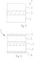
- Fig. 1 a three-layer structure of a composite material 1 according to the invention is shown according to a first embodiment.
- the composite material 1 comprises a first electrical tape layer 2, a second electrical tape layer 4 and a polymer layer 3 arranged between them.
- Fig. 2 shows a second embodiment of the composite material 5 according to the invention with a first and second electrical tape layer 2, 4 and a polymer layer 3 arranged between them.
- the two electrical tape layers 2, 4 each have an insulation layer 6. According to a preferred embodiment, this is formed by a thermally activatable adhesive.
- a multi-layer structure 7 is shown using the composite material 5 according to the second embodiment.
- the individual layers of the composite material 5 are arranged one above the other to form a stack. If the insulation layer 6 is formed by a thermally activated adhesive, the multilayer structure 7 has a homogeneous insulation layer 6 between the individual lamellae (not shown).
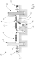
- Fig. 4 shows a process diagram for the continuous production of the composite material 1, 5 according to the invention by means of a strip coating system 10.
- the system 10 has a first and a second strip unwinding station 11, 12, with which a first and a second grain-oriented electrical strip layer 2, 4 is provided.
- the system 10 also has a stapling device 13 and a first and a second strip storage device 14, 20, which allow a coil to be changed without having to interrupt the process.
- the first electrical strip layer 2 is first fed to a pretreatment stage 15 if necessary in order to free the surface of the electrical strip layer 2 from adhering dirt particles and oils.
- the polymeric agent (not shown) is then applied to one side via an application roller 16.
- the electrical strip layer 2 coated with the polymeric agent then passes through a 2-zone oven 17, in which the applied coating is pre-dried at 100 - 120 °C. The solvent is removed here.
- the electrical steel layer 2 is heated to the PMT (170 - 190 °C).
- a second electrical steel layer 4 is provided from the second unwinding station 12 and initially fed to a heating station 17, in which the second electrical steel layer 4 is also heated to the PMT.
- a doubling station 18 the two electrical steel layers 2, 4 are laminated together to form the composite material 1, 5 under a pressure of 5 kN and at a temperature of 150 - 170 °C.
- the still hot composite material 1, 5 then passes through a cooling station, where it cools to room temperature and is then wound into a coil on a strip winding station 21.
Landscapes
- Engineering & Computer Science (AREA)
- Power Engineering (AREA)
- Chemical & Material Sciences (AREA)
- Manufacturing & Machinery (AREA)
- Physics & Mathematics (AREA)
- Organic Chemistry (AREA)
- Metallurgy (AREA)
- Electromagnetism (AREA)
- Thermal Sciences (AREA)
- Crystallography & Structural Chemistry (AREA)
- Mechanical Engineering (AREA)
- Materials Engineering (AREA)
- Polymers & Plastics (AREA)
- Chemical Kinetics & Catalysis (AREA)
- Health & Medical Sciences (AREA)
- Medicinal Chemistry (AREA)
- Laminated Bodies (AREA)
- Organic Insulating Materials (AREA)
- Manufacturing Cores, Coils, And Magnets (AREA)
Priority Applications (1)
| Application Number | Priority Date | Filing Date | Title |
|---|---|---|---|
| PL17710683.8T PL3589486T3 (pl) | 2017-03-03 | 2017-03-03 | Materiał kompozytowy do transformatora |
Applications Claiming Priority (1)
| Application Number | Priority Date | Filing Date | Title |
|---|---|---|---|
| PCT/EP2017/055068 WO2018157946A1 (de) | 2017-03-03 | 2017-03-03 | Verbundwerkstoff für einen transformator |
Publications (2)
| Publication Number | Publication Date |
|---|---|
| EP3589486A1 EP3589486A1 (de) | 2020-01-08 |
| EP3589486B1 true EP3589486B1 (de) | 2024-10-09 |
Family
ID=58277260
Family Applications (1)
| Application Number | Title | Priority Date | Filing Date |
|---|---|---|---|
| EP17710683.8A Active EP3589486B1 (de) | 2017-03-03 | 2017-03-03 | Verbundwerkstoff für einen transformator |
Country Status (9)
| Country | Link |
|---|---|
| US (1) | US20210407732A1 (pl) |
| EP (1) | EP3589486B1 (pl) |
| JP (1) | JP2020511005A (pl) |
| KR (1) | KR20190125390A (pl) |
| CN (1) | CN110621496A (pl) |
| BR (1) | BR112019018002A2 (pl) |
| MX (1) | MX2019010448A (pl) |
| PL (1) | PL3589486T3 (pl) |
| WO (1) | WO2018157946A1 (pl) |
Families Citing this family (1)
| Publication number | Priority date | Publication date | Assignee | Title |
|---|---|---|---|---|
| EP4082772B1 (de) * | 2021-04-30 | 2025-10-08 | Wickeder Westfalenstahl GmbH | Elektroblech, verwendung eines elektroblechs und verfahren zur herstellung eines elektroblechs |
Family Cites Families (9)
| Publication number | Priority date | Publication date | Assignee | Title |
|---|---|---|---|---|
| EP0305966B1 (en) * | 1987-08-31 | 1992-11-04 | Nippon Steel Corporation | Method for producing grain-oriented electrical steel sheet having metallic luster and excellent punching property |
| JP3239312B2 (ja) * | 1994-03-31 | 2001-12-17 | 川崎製鉄株式会社 | 耐食性に優れた電気絶縁被膜を有する電磁鋼板 |
| US5753362A (en) * | 1994-08-12 | 1998-05-19 | Soken Chemical & Engineering Co., Ltd. | Acrylic sheet, acrylic adhesive sheet and processes for preparing the sheets |
| US6191510B1 (en) | 1997-12-19 | 2001-02-20 | 3M Innovative Properties Company | Internally damped stator, rotor, and transformer and a method of making |
| CN101616940B (zh) * | 2006-09-20 | 2012-06-20 | 东丽株式会社 | 热塑性共聚物的制造方法 |
| JP2009063122A (ja) * | 2007-09-07 | 2009-03-26 | Nitto Denko Corp | 制振シート |
| DE102008008781A1 (de) * | 2008-02-12 | 2009-08-20 | Thyssenkrupp Electrical Steel Gmbh | Verfahren zur Herstellung eines kornorientierten Elektrobands |
| KR102037649B1 (ko) * | 2012-04-27 | 2019-10-29 | 주식회사 쿠라레 | 아크릴계 점착제 조성물 및 점착 제품 |
| CN105131750B (zh) * | 2015-08-31 | 2017-06-16 | 马鞍山市鸿翮实业有限公司 | 一种电工钢用环保型自粘结涂料及其制备方法 |
-
2017
- 2017-03-03 JP JP2019547429A patent/JP2020511005A/ja not_active Withdrawn
- 2017-03-03 CN CN201780088011.1A patent/CN110621496A/zh active Pending
- 2017-03-03 US US16/490,212 patent/US20210407732A1/en not_active Abandoned
- 2017-03-03 WO PCT/EP2017/055068 patent/WO2018157946A1/de not_active Ceased
- 2017-03-03 BR BR112019018002A patent/BR112019018002A2/pt not_active Application Discontinuation
- 2017-03-03 MX MX2019010448A patent/MX2019010448A/es unknown
- 2017-03-03 KR KR1020197028725A patent/KR20190125390A/ko not_active Withdrawn
- 2017-03-03 PL PL17710683.8T patent/PL3589486T3/pl unknown
- 2017-03-03 EP EP17710683.8A patent/EP3589486B1/de active Active
Also Published As
| Publication number | Publication date |
|---|---|
| BR112019018002A2 (pt) | 2020-04-28 |
| PL3589486T3 (pl) | 2025-09-01 |
| JP2020511005A (ja) | 2020-04-09 |
| KR20190125390A (ko) | 2019-11-06 |
| CN110621496A (zh) | 2019-12-27 |
| WO2018157946A1 (de) | 2018-09-07 |
| EP3589486A1 (de) | 2020-01-08 |
| US20210407732A1 (en) | 2021-12-30 |
| MX2019010448A (es) | 2020-01-30 |
Similar Documents
| Publication | Publication Date | Title |
|---|---|---|
| EP3589485B1 (de) | Verbundwerkstoff für ein stator- und rotorpaket | |
| DE2518193C2 (de) | Verfahren zum Herstellen von Laminaten | |
| DE4420613C1 (de) | Durchbrandblocker für Flugzeugrümpfe | |
| DE112006002571T5 (de) | Kupferplattierter Schichtstoff, gedruckte Leiterplatte, mehrschichtige gedruckte Leiterplatte und Verfahren zum Herstellen derselben | |
| WO2008095532A1 (de) | Isoliermaterial für elektrische maschinen | |
| DE69528135T2 (de) | Verbundstoff mit uv-gehärteter beschichtung und herstellungsverfahren | |
| DE19846902A1 (de) | Elektronenstrahlvernetzung und UV-Vernetzung von Masseschichten sowie Produkte, die mit diesen Masseschichten hergestellt werden | |
| DE3333155A1 (de) | Blech fuer lamellierte eisenkerne | |
| WO1993010202A1 (de) | Heissiegelbeschichtung auf dispersionsbasis | |
| DE602004013278T2 (de) | Glasfaser panel mit beidseitiger glasfasermatte | |
| EP3589486B1 (de) | Verbundwerkstoff für einen transformator | |
| DE102018206151A1 (de) | Beschichtetes blechband und verfahren zur herstellung | |
| DE2749501B2 (de) | Mehrschichtmembran für Lautsprecher | |
| EP0027945A2 (de) | Verbundplatte | |
| DE60101355T2 (de) | Metallbeschichtetes Hochdrucklaminat | |
| DE1289159B (de) | Schichtstoffisolierung fuer Hochspannung fuehrende Teile | |
| DE3940236C2 (pl) | ||
| DE102018204876A1 (de) | Elektromotor mit geschrägtem Stator und/oder Rotor enthaltend mindestens eine Schicht eines Verbundwerkstoffs | |
| EP2632973B1 (de) | Isolationsmaterialvorprodukt und isolationsmaterial | |
| DE102024121479A1 (de) | Glasvlies und mit einem Glasvlies versehenes Mineralwollformteil | |
| DE4036803A1 (de) | Verfahren zur herstellung von kupferkaschierten schichtpressstofftafeln | |
| DE9314818U1 (de) | Selbsthaftende Heißklebefolie |
Legal Events
| Date | Code | Title | Description |
|---|---|---|---|
| STAA | Information on the status of an ep patent application or granted ep patent |
Free format text: STATUS: UNKNOWN |
|
| STAA | Information on the status of an ep patent application or granted ep patent |
Free format text: STATUS: THE INTERNATIONAL PUBLICATION HAS BEEN MADE |
|
| PUAI | Public reference made under article 153(3) epc to a published international application that has entered the european phase |
Free format text: ORIGINAL CODE: 0009012 |
|
| STAA | Information on the status of an ep patent application or granted ep patent |
Free format text: STATUS: REQUEST FOR EXAMINATION WAS MADE |
|
| 17P | Request for examination filed |
Effective date: 20190903 |
|
| AK | Designated contracting states |
Kind code of ref document: A1 Designated state(s): AL AT BE BG CH CY CZ DE DK EE ES FI FR GB GR HR HU IE IS IT LI LT LU LV MC MK MT NL NO PL PT RO RS SE SI SK SM TR |
|
| AX | Request for extension of the european patent |
Extension state: BA ME |
|
| DAV | Request for validation of the european patent (deleted) | ||
| DAX | Request for extension of the european patent (deleted) | ||
| STAA | Information on the status of an ep patent application or granted ep patent |
Free format text: STATUS: EXAMINATION IS IN PROGRESS |
|
| 17Q | First examination report despatched |
Effective date: 20200806 |
|
| RAP3 | Party data changed (applicant data changed or rights of an application transferred) |
Owner name: THYSSENKRUPP ELECTRICAL STEEL GMBH Owner name: THYSSENKRUPP AG |
|
| GRAP | Despatch of communication of intention to grant a patent |
Free format text: ORIGINAL CODE: EPIDOSNIGR1 |
|
| STAA | Information on the status of an ep patent application or granted ep patent |
Free format text: STATUS: GRANT OF PATENT IS INTENDED |
|
| INTG | Intention to grant announced |
Effective date: 20240503 |
|
| GRAS | Grant fee paid |
Free format text: ORIGINAL CODE: EPIDOSNIGR3 |
|
| GRAA | (expected) grant |
Free format text: ORIGINAL CODE: 0009210 |
|
| STAA | Information on the status of an ep patent application or granted ep patent |
Free format text: STATUS: THE PATENT HAS BEEN GRANTED |
|
| RIN1 | Information on inventor provided before grant (corrected) |
Inventor name: LEWE, TOBIAS Inventor name: ROGNER, INGO Inventor name: WANG, CHAOYONG, Inventor name: SCHEPERS, CARSTEN Inventor name: LEMAITRE, REGIS Inventor name: LAHN, LUDGER Inventor name: HECHT, CHRISTIAN |
|
| AK | Designated contracting states |
Kind code of ref document: B1 Designated state(s): AL AT BE BG CH CY CZ DE DK EE ES FI FR GB GR HR HU IE IS IT LI LT LU LV MC MK MT NL NO PL PT RO RS SE SI SK SM TR |
|
| REG | Reference to a national code |
Ref country code: CH Ref legal event code: EP |
|
| REG | Reference to a national code |
Ref country code: DE Ref legal event code: R096 Ref document number: 502017016468 Country of ref document: DE |
|
| REG | Reference to a national code |
Ref country code: IE Ref legal event code: FG4D Free format text: LANGUAGE OF EP DOCUMENT: GERMAN |
|
| P01 | Opt-out of the competence of the unified patent court (upc) registered |
Free format text: CASE NUMBER: APP_52767/2024 Effective date: 20240920 |
|
| RAP2 | Party data changed (patent owner data changed or rights of a patent transferred) |
Owner name: THYSSENKRUPP ELECTRICAL STEEL GMBH |
|
| REG | Reference to a national code |
Ref country code: LT Ref legal event code: MG9D |
|
| REG | Reference to a national code |
Ref country code: NL Ref legal event code: MP Effective date: 20241009 |
|
| PG25 | Lapsed in a contracting state [announced via postgrant information from national office to epo] |
Ref country code: NL Free format text: LAPSE BECAUSE OF FAILURE TO SUBMIT A TRANSLATION OF THE DESCRIPTION OR TO PAY THE FEE WITHIN THE PRESCRIBED TIME-LIMIT Effective date: 20241009 |
|
| PG25 | Lapsed in a contracting state [announced via postgrant information from national office to epo] |
Ref country code: NL Free format text: LAPSE BECAUSE OF FAILURE TO SUBMIT A TRANSLATION OF THE DESCRIPTION OR TO PAY THE FEE WITHIN THE PRESCRIBED TIME-LIMIT Effective date: 20241009 |
|
| PG25 | Lapsed in a contracting state [announced via postgrant information from national office to epo] |
Ref country code: PT Free format text: LAPSE BECAUSE OF FAILURE TO SUBMIT A TRANSLATION OF THE DESCRIPTION OR TO PAY THE FEE WITHIN THE PRESCRIBED TIME-LIMIT Effective date: 20250210 Ref country code: IS Free format text: LAPSE BECAUSE OF FAILURE TO SUBMIT A TRANSLATION OF THE DESCRIPTION OR TO PAY THE FEE WITHIN THE PRESCRIBED TIME-LIMIT Effective date: 20250209 Ref country code: HR Free format text: LAPSE BECAUSE OF FAILURE TO SUBMIT A TRANSLATION OF THE DESCRIPTION OR TO PAY THE FEE WITHIN THE PRESCRIBED TIME-LIMIT Effective date: 20241009 |
|
| PGFP | Annual fee paid to national office [announced via postgrant information from national office to epo] |
Ref country code: DE Payment date: 20250325 Year of fee payment: 9 |
|
| PG25 | Lapsed in a contracting state [announced via postgrant information from national office to epo] |
Ref country code: FI Free format text: LAPSE BECAUSE OF FAILURE TO SUBMIT A TRANSLATION OF THE DESCRIPTION OR TO PAY THE FEE WITHIN THE PRESCRIBED TIME-LIMIT Effective date: 20241009 |
|
| PG25 | Lapsed in a contracting state [announced via postgrant information from national office to epo] |
Ref country code: BG Free format text: LAPSE BECAUSE OF FAILURE TO SUBMIT A TRANSLATION OF THE DESCRIPTION OR TO PAY THE FEE WITHIN THE PRESCRIBED TIME-LIMIT Effective date: 20241009 |
|
| PG25 | Lapsed in a contracting state [announced via postgrant information from national office to epo] |
Ref country code: ES Free format text: LAPSE BECAUSE OF FAILURE TO SUBMIT A TRANSLATION OF THE DESCRIPTION OR TO PAY THE FEE WITHIN THE PRESCRIBED TIME-LIMIT Effective date: 20241009 |
|
| PG25 | Lapsed in a contracting state [announced via postgrant information from national office to epo] |
Ref country code: NO Free format text: LAPSE BECAUSE OF FAILURE TO SUBMIT A TRANSLATION OF THE DESCRIPTION OR TO PAY THE FEE WITHIN THE PRESCRIBED TIME-LIMIT Effective date: 20250109 |
|
| PG25 | Lapsed in a contracting state [announced via postgrant information from national office to epo] |
Ref country code: LV Free format text: LAPSE BECAUSE OF FAILURE TO SUBMIT A TRANSLATION OF THE DESCRIPTION OR TO PAY THE FEE WITHIN THE PRESCRIBED TIME-LIMIT Effective date: 20241009 Ref country code: GR Free format text: LAPSE BECAUSE OF FAILURE TO SUBMIT A TRANSLATION OF THE DESCRIPTION OR TO PAY THE FEE WITHIN THE PRESCRIBED TIME-LIMIT Effective date: 20250110 |
|
| PGFP | Annual fee paid to national office [announced via postgrant information from national office to epo] |
Ref country code: FR Payment date: 20250325 Year of fee payment: 9 Ref country code: CZ Payment date: 20250121 Year of fee payment: 9 |
|
| PGFP | Annual fee paid to national office [announced via postgrant information from national office to epo] |
Ref country code: IT Payment date: 20250325 Year of fee payment: 9 Ref country code: GB Payment date: 20250326 Year of fee payment: 9 |
|
| PG25 | Lapsed in a contracting state [announced via postgrant information from national office to epo] |
Ref country code: RS Free format text: LAPSE BECAUSE OF FAILURE TO SUBMIT A TRANSLATION OF THE DESCRIPTION OR TO PAY THE FEE WITHIN THE PRESCRIBED TIME-LIMIT Effective date: 20250109 |
|
| PGFP | Annual fee paid to national office [announced via postgrant information from national office to epo] |
Ref country code: TR Payment date: 20250213 Year of fee payment: 9 |
|
| PG25 | Lapsed in a contracting state [announced via postgrant information from national office to epo] |
Ref country code: SM Free format text: LAPSE BECAUSE OF FAILURE TO SUBMIT A TRANSLATION OF THE DESCRIPTION OR TO PAY THE FEE WITHIN THE PRESCRIBED TIME-LIMIT Effective date: 20241009 |
|
| PG25 | Lapsed in a contracting state [announced via postgrant information from national office to epo] |
Ref country code: DK Free format text: LAPSE BECAUSE OF FAILURE TO SUBMIT A TRANSLATION OF THE DESCRIPTION OR TO PAY THE FEE WITHIN THE PRESCRIBED TIME-LIMIT Effective date: 20241009 |
|
| REG | Reference to a national code |
Ref country code: DE Ref legal event code: R097 Ref document number: 502017016468 Country of ref document: DE |
|
| PG25 | Lapsed in a contracting state [announced via postgrant information from national office to epo] |
Ref country code: EE Free format text: LAPSE BECAUSE OF FAILURE TO SUBMIT A TRANSLATION OF THE DESCRIPTION OR TO PAY THE FEE WITHIN THE PRESCRIBED TIME-LIMIT Effective date: 20241009 |
|
| PG25 | Lapsed in a contracting state [announced via postgrant information from national office to epo] |
Ref country code: RO Free format text: LAPSE BECAUSE OF FAILURE TO SUBMIT A TRANSLATION OF THE DESCRIPTION OR TO PAY THE FEE WITHIN THE PRESCRIBED TIME-LIMIT Effective date: 20241009 |
|
| PG25 | Lapsed in a contracting state [announced via postgrant information from national office to epo] |
Ref country code: SK Free format text: LAPSE BECAUSE OF FAILURE TO SUBMIT A TRANSLATION OF THE DESCRIPTION OR TO PAY THE FEE WITHIN THE PRESCRIBED TIME-LIMIT Effective date: 20241009 |
|
| PLBE | No opposition filed within time limit |
Free format text: ORIGINAL CODE: 0009261 |
|
| STAA | Information on the status of an ep patent application or granted ep patent |
Free format text: STATUS: NO OPPOSITION FILED WITHIN TIME LIMIT |
|
| PG25 | Lapsed in a contracting state [announced via postgrant information from national office to epo] |
Ref country code: SE Free format text: LAPSE BECAUSE OF FAILURE TO SUBMIT A TRANSLATION OF THE DESCRIPTION OR TO PAY THE FEE WITHIN THE PRESCRIBED TIME-LIMIT Effective date: 20241009 |
|
| 26N | No opposition filed |
Effective date: 20250710 |
|
| PG25 | Lapsed in a contracting state [announced via postgrant information from national office to epo] |
Ref country code: MC Free format text: LAPSE BECAUSE OF FAILURE TO SUBMIT A TRANSLATION OF THE DESCRIPTION OR TO PAY THE FEE WITHIN THE PRESCRIBED TIME-LIMIT Effective date: 20241009 |
|
| PGFP | Annual fee paid to national office [announced via postgrant information from national office to epo] |
Ref country code: PL Payment date: 20250224 Year of fee payment: 9 |
|
| REG | Reference to a national code |
Ref country code: CH Ref legal event code: H13 Free format text: ST27 STATUS EVENT CODE: U-0-0-H10-H13 (AS PROVIDED BY THE NATIONAL OFFICE) Effective date: 20251023 |
|
| PG25 | Lapsed in a contracting state [announced via postgrant information from national office to epo] |
Ref country code: LU Free format text: LAPSE BECAUSE OF NON-PAYMENT OF DUE FEES Effective date: 20250303 |
|
| REG | Reference to a national code |
Ref country code: BE Ref legal event code: MM Effective date: 20250331 |
|
| PG25 | Lapsed in a contracting state [announced via postgrant information from national office to epo] |
Ref country code: BE Free format text: LAPSE BECAUSE OF NON-PAYMENT OF DUE FEES Effective date: 20250331 |
|
| PG25 | Lapsed in a contracting state [announced via postgrant information from national office to epo] |
Ref country code: CH Free format text: LAPSE BECAUSE OF NON-PAYMENT OF DUE FEES Effective date: 20250331 |
|
| PG25 | Lapsed in a contracting state [announced via postgrant information from national office to epo] |
Ref country code: IE Free format text: LAPSE BECAUSE OF NON-PAYMENT OF DUE FEES Effective date: 20250303 |