EP3589347B1 - Vorrichtung zum brandschutz bei der therapie mit sauerstoffangereicherten atemgasen - Google Patents
Vorrichtung zum brandschutz bei der therapie mit sauerstoffangereicherten atemgasen Download PDFInfo
- Publication number
- EP3589347B1 EP3589347B1 EP18709517.9A EP18709517A EP3589347B1 EP 3589347 B1 EP3589347 B1 EP 3589347B1 EP 18709517 A EP18709517 A EP 18709517A EP 3589347 B1 EP3589347 B1 EP 3589347B1
- Authority
- EP
- European Patent Office
- Prior art keywords
- breathable gas
- oxygenated
- valve
- oxygenated breathable
- oxygen
- Prior art date
- Legal status (The legal status is an assumption and is not a legal conclusion. Google has not performed a legal analysis and makes no representation as to the accuracy of the status listed.)
- Active
Links
Images


Classifications
-
- A—HUMAN NECESSITIES
- A61—MEDICAL OR VETERINARY SCIENCE; HYGIENE
- A61M—DEVICES FOR INTRODUCING MEDIA INTO, OR ONTO, THE BODY; DEVICES FOR TRANSDUCING BODY MEDIA OR FOR TAKING MEDIA FROM THE BODY; DEVICES FOR PRODUCING OR ENDING SLEEP OR STUPOR
- A61M16/00—Devices for influencing the respiratory system of patients by gas treatment, e.g. ventilators; Tracheal tubes
- A61M16/10—Preparation of respiratory gases or vapours
- A61M16/1005—Preparation of respiratory gases or vapours with O2 features or with parameter measurement
-
- A—HUMAN NECESSITIES
- A61—MEDICAL OR VETERINARY SCIENCE; HYGIENE
- A61M—DEVICES FOR INTRODUCING MEDIA INTO, OR ONTO, THE BODY; DEVICES FOR TRANSDUCING BODY MEDIA OR FOR TAKING MEDIA FROM THE BODY; DEVICES FOR PRODUCING OR ENDING SLEEP OR STUPOR
- A61M16/00—Devices for influencing the respiratory system of patients by gas treatment, e.g. ventilators; Tracheal tubes
- A61M16/06—Respiratory or anaesthetic masks
- A61M16/0666—Nasal cannulas or tubing
- A61M16/0672—Nasal cannula assemblies for oxygen therapy
-
- A—HUMAN NECESSITIES
- A61—MEDICAL OR VETERINARY SCIENCE; HYGIENE
- A61M—DEVICES FOR INTRODUCING MEDIA INTO, OR ONTO, THE BODY; DEVICES FOR TRANSDUCING BODY MEDIA OR FOR TAKING MEDIA FROM THE BODY; DEVICES FOR PRODUCING OR ENDING SLEEP OR STUPOR
- A61M16/00—Devices for influencing the respiratory system of patients by gas treatment, e.g. ventilators; Tracheal tubes
- A61M16/20—Valves specially adapted to medical respiratory devices
-
- A—HUMAN NECESSITIES
- A61—MEDICAL OR VETERINARY SCIENCE; HYGIENE
- A61M—DEVICES FOR INTRODUCING MEDIA INTO, OR ONTO, THE BODY; DEVICES FOR TRANSDUCING BODY MEDIA OR FOR TAKING MEDIA FROM THE BODY; DEVICES FOR PRODUCING OR ENDING SLEEP OR STUPOR
- A61M16/00—Devices for influencing the respiratory system of patients by gas treatment, e.g. ventilators; Tracheal tubes
- A61M16/20—Valves specially adapted to medical respiratory devices
- A61M16/201—Controlled valves
-
- A—HUMAN NECESSITIES
- A62—LIFE-SAVING; FIRE-FIGHTING
- A62C—FIRE-FIGHTING
- A62C2/00—Fire prevention or containment
- A62C2/04—Removing or cutting-off the supply of inflammable material
-
- F—MECHANICAL ENGINEERING; LIGHTING; HEATING; WEAPONS; BLASTING
- F16—ENGINEERING ELEMENTS AND UNITS; GENERAL MEASURES FOR PRODUCING AND MAINTAINING EFFECTIVE FUNCTIONING OF MACHINES OR INSTALLATIONS; THERMAL INSULATION IN GENERAL
- F16K—VALVES; TAPS; COCKS; ACTUATING-FLOATS; DEVICES FOR VENTING OR AERATING
- F16K17/00—Safety valves; Equalising valves, e.g. pressure relief valves
- F16K17/36—Safety valves; Equalising valves, e.g. pressure relief valves actuated in consequence of extraneous circumstances, e.g. shock, change of position
- F16K17/38—Safety valves; Equalising valves, e.g. pressure relief valves actuated in consequence of extraneous circumstances, e.g. shock, change of position of excessive temperature
- F16K17/383—Safety valves; Equalising valves, e.g. pressure relief valves actuated in consequence of extraneous circumstances, e.g. shock, change of position of excessive temperature the valve comprising fusible, softening or meltable elements, e.g. used as link, blocking element, seal, closure plug
-
- A—HUMAN NECESSITIES
- A61—MEDICAL OR VETERINARY SCIENCE; HYGIENE
- A61M—DEVICES FOR INTRODUCING MEDIA INTO, OR ONTO, THE BODY; DEVICES FOR TRANSDUCING BODY MEDIA OR FOR TAKING MEDIA FROM THE BODY; DEVICES FOR PRODUCING OR ENDING SLEEP OR STUPOR
- A61M16/00—Devices for influencing the respiratory system of patients by gas treatment, e.g. ventilators; Tracheal tubes
- A61M16/08—Bellows; Connecting tubes ; Water traps; Patient circuits
- A61M16/0816—Joints or connectors
Definitions
- the present invention relates to a device for supplying a patient with oxygen-enriched breathing gas with a fire protection device.
- Such oxygen supply is usually carried out using a tube system that can be used to supply oxygen or oxygen-enriched air to a patient.
- the oxygen can be provided from pressure bottles, liquid oxygen vessels (Dewar), from oxygen concentrators or generators, or from central oxygen supply systems.
- the oxygen can be supplied to the patient via a so-called nasal cannula, via a breathing mask (closed or open) or via a ventilation tube through the mouth/nose or tracheostomy.
- COPD chronic obstructive pulmonary disease
- Approximately 20% of patients cannot refrain from smoking during oxygen treatment despite warnings see West GA, Primeau P. Nonmedical hazards of long-term oxygen therapy. Respir Care. 1983; 28:906-12 ).
- the oxygen causes the fire to accelerate considerably, the cigarettes can burst into flames, and the plastic nasal cannula or breathing mask as well as the patient's clothing or bedding often catch fire.
- the incoming oxygen accelerates the fire considerably and within a short time the patient's bed or the patient himself can be in bright flames. Deaths have been reported from these fires (see Morbidity and mortality weekly report. Fatal fires associated with smoking during long-term oxygen therapy. Maine, Massachusetts, New Hampshire, and Oklahoma. 2000-2007. MMWR. 2008; 57:852-854 ).
- the WO 2014/020334 A1 a valve that can be built into the supply hose and which, when reached by flames, automatically stops the flow so that no more oxygen can flow in.
- This system has the disadvantage, however, that it is usually built into the end of the oxygen hose, where the hose splits into two hoses which then form the so-called nasal cannula through which the patient receives oxygen.
- the fire must therefore first spread from the primary source of the fire via these two hoses to the connection to the common supply hose in order to activate the valve. This causes oxygen to flow in for an unnecessarily long time.
- the supply hose in front of the valve can be caught in the flames, melt and the oxygen flow can be allowed to flow again.
- EP 2 682 149 A2 describes a system in which a thin copper wire is integrated into the hose, to which a voltage is applied or whose resistance is measured. If the hose catches fire, this copper wire melts and the oxygen supply is interrupted via a corresponding monitoring device. This arrangement can certainly be used much earlier than the one in WO 2014/020334 A1
- the device described above can prevent the flow of oxygen, but it is very complex to manufacture. Since a closed circuit is required, the supply to the patient's nasal cannula must be made via two tubes, between which there must be reliable electrical contacts. The electrical connection of the copper wire to the monitoring device is also complex.
- US 5,927,312 describes a system with a self-extinguishing hose, where in the event of a fire a closure is triggered, which essentially stops the flow of gas. This is achieved by a combination of different materials, whereby a heat-sensitive material, which is attached outside the pipe at the desired closure point, expands or contracts or melts if it is attached inside the pipe.
- a heat-sensitive material which is attached outside the pipe at the desired closure point, expands or contracts or melts if it is attached inside the pipe.
- the installation of this system in the nasal passages would lead to an undesirable increase in material and weight in the facial area.
- the system described has the same disadvantages as WO 2014/020334 A1 .
- the present invention is directed to a device for supplying a patient with oxygen-enriched breathing gas.
- the device has a device for providing oxygen-enriched breathing gas, a supply line connected to the device, via which the oxygen-enriched breathing gas can be supplied from the device to the patient, and a detector which is suitable for detecting an increase in the volume flow of oxygen-enriched breathing gas and/or a drop in pressure of the oxygen-enriched breathing gas.
- the device is suitable and designed to control the supply of the oxygen-enriched Breathing gas in the event of an increase in the volume flow of oxygen-enriched breathing gas and/or a drop in the pressure of the oxygen-enriched breathing gas.
- the supply line has a region close to the patient with an increased flow resistance, which is designed in such a way that the flow resistance is reduced under the influence of heat by melting the hose.
- the device also has a valve which prevents the supply of oxygen-enriched breathing gas in the event of an increase in the volume flow of oxygen-enriched breathing gas and/or a drop in the pressure of the oxygen-enriched breathing gas, wherein the valve is suitable for automatically mechanically preventing the supply of oxygen-enriched breathing gas in the event of an increase in the volume flow of oxygen-enriched breathing gas and/or a drop in the pressure of the oxygen-enriched breathing gas.
- the invention is based on the principle that a flow restriction occurs directly at the point where the oxygen or oxygen-enriched breathing air is delivered (in the simplest case, for example, by narrowing the cross-section of the supply line), which leads to a relative increase in pressure in the proximal area of the supply line.
- this flow restriction is lifted again, since the area with an increased flow resistance is designed in such a way that the flow resistance is reduced under the influence of heat.
- the cross-sectional constriction can melt under the influence of heat. This causes an increase in the volume flow or a drop in pressure in the supply line, which in turn leads to the supply of the oxygen-enriched breathing gas being stopped. This is done by closing the valve.
- the device according to the invention is technically relatively simple and therefore inexpensive to manufacture and guarantees an early and safe stop of the oxygen supply, since the detection of the fire (via the area with an increased flow resistance) takes place close to the patient.
- the device for providing oxygen-enriched breathing gas can be a pressure bottle, a liquid oxygen vessel (Dewar), an oxygen concentrator or generator or a central oxygen supply system.
- the device is suitable for providing a breathing gas with a higher oxygen content than ambient air.
- the oxygen-enriched breathing gas can also be pure Oxygen.
- the preferred way to prevent or interrupt the supply of breathing gas is to switch it off (e.g. concentrator) or close a valve (e.g. pressure bottle).
- the former could also be implemented very easily as a ballast device into which the plug of the concentrator, for example, is inserted. This has the advantage that existing concentrators can be used with the device according to the invention without complicated or expensive retrofitting.
- the supply line via which the oxygen-enriched breathing gas can be supplied to a patient from the device for providing oxygen-enriched breathing gas, is connected directly or indirectly to the device for providing oxygen-enriched breathing gas.
- a device for regulating the supply flow and/or the pressure in the supply line can be present.
- the supply line preferably has a supply hose with a nasal cannula or a connector for connection to a breathing mask or a ventilation tube.
- the area with an increased flow resistance is preferably provided at the patient-side end of the supply hose, on the nasal cannula and/or on the connector.
- the area with an increased flow resistance is preferably provided as close as possible to the exit point of the oxygen-enriched breathing gas, since the fire develops most quickly at this exit point.
- the distance between the region with an increased flow resistance and the exit point of the oxygen-enriched breathing gas is less than 10 cm, more preferably less than 5 cm and particularly preferably less than 3 cm.
- the increase in the volume flow of oxygen-enriched breathing gas and/or the pressure drop of the oxygen-enriched breathing gas in the supply line is detected or measured and the device for providing oxygen-enriched breathing gas or the valve is switched off or closed by means of a suitable control.
- the device preferably has a detector which is suitable for detecting an increase in the volume flow of oxygen-enriched breathing gas in the supply line and/or a pressure drop of the oxygen-enriched breathing gas in the supply line.
- the detector can be provided in the supply line or on the device for providing oxygen-enriched breathing gas.
- the device also preferably has a control which is suitable for closing the valve and/or the device for To switch off the provision of oxygen-enriched breathing gas if the detector detects an increase in the volume flow of oxygen-enriched breathing gas and/or a drop in pressure of the oxygen-enriched breathing gas.
- the detector is suitable for detecting a relative increase in the volume flow of oxygen-enriched breathing gas in the supply line by at least 50%, preferably by at least 30%, more preferably by at least 20%, particularly preferably by at least 10%.
- the detector is preferably suitable for detecting a relative drop in pressure of the oxygen-enriched breathing gas in the supply line of at least 50%, preferably by 30%, more preferably by at least 20% and particularly preferably by at least 10%.
- the control is preferably designed to measure the volume flow of oxygen-enriched breathing gas and/or the pressure of the oxygen-enriched breathing gas and to define a threshold value during normal operation, preferably after a predetermined period of time after the start of the provision of oxygen-enriched breathing gas, by means of the detector.
- the control is also preferably designed to prevent the supply of the oxygen-enriched breathing gas if a minimum percentage deviation of the measured volume flow of oxygen-enriched breathing gas and/or the measured pressure of the oxygen-enriched breathing gas from the threshold value is determined.
- the minimum percentage deviation is preferably 50%, more preferably 30%, even more preferably 20% and particularly preferably 10%.
- the predetermined time period is preferably at least 10 s, more preferably at least 20 s, even more preferably at least 30 s and particularly preferably at least 1 min. This ensures that the threshold value is only determined when a flow equilibrium has already been established and ideally the nasal cannula is already attached to the patient, so that deviations from this normal or threshold value can subsequently be determined.
- the device may comprise a device or mechanism which ensures that the supply of breathing gas is briefly interrupted when the supply line is connected to the device for providing oxygen-enriched breathing gas.
- the control of the device may set an incorrect threshold value.
- the brief interruption triggers the control to set a new threshold value after the supply line is connected to the concentrator.
- the hose connection of the supply line could be axially movable slightly so that when the hose is plugged in and removed, the breathing gas supply is interrupted or the flow or pressure measurement is triggered again.
- the valve itself is suitable for automatically mechanically stopping the supply of oxygen-enriched breathing gas in the event of an increase in the volume flow of oxygen-enriched breathing gas through the valve and/or a drop in pressure of the oxygen-enriched breathing gas at the valve.
- the valve preferably has a spring or a magnet which biases the valve into the open position against the flow direction of the oxygen-enriched breathing gas.
- the spring constant of the spring or the force of the magnet is preferably dimensioned such that the valve is closed at a volume flow of 5 l/min and a sudden pressure drop of at least 50%, preferably of at least 30%, particularly preferably of at least 20%.
- the region with an increased flow resistance can in principle be provided by very different structural features in all possible variants, as long as it is designed such that the flow resistance is reduced under the influence of heat.
- the minimum period is preferably 10 seconds, more preferably 5 seconds, even more preferably 3 seconds and particularly preferably 2 seconds.
- the minimum temperature is preferably 140°C, more preferably 120°C and particularly preferably 100°C. Accordingly, it is particularly preferred that the region with an increased flow resistance is designed such that the flow resistance is reduced when the region is exposed to a temperature of at least 100°C for at least 2 seconds.
- the flow resistance of the area should be reduced under the influence of heat to such an extent that the resulting increase in volume flow or the resulting drop in pressure can be detected by a detector or sensor and/or leads directly to the valve being closed. Accordingly, the reduction in flow resistance required according to the invention depends on the type of detector used or the sensitivity of the valve as well as on the conditions (pressure and volume flow) under which the breathing gas is administered.
- the latter depend, among other things, on the patient (some patients are supplied with a volume flow of, for example, 5 l/min, others with a volume flow of, for example, 3 l/min) and on the type of device used to provide the enriched breathing gas.
- the region with an increased flow resistance has a flow resistance that corresponds to an aperture with a clear diameter of between 0.1 mm and 4 mm, more preferably between 0.3 mm and 3 mm, and particularly preferably between 0.5 mm and 2 mm. It is further preferred that the region with an increased flow resistance has a flow resistance that is less than or equal to the flow resistance of an aperture with a clear diameter of 2 mm, preferably 1.5 mm, and particularly preferably 1 mm.
- the largest opening in the region with an increased flow resistance has a cross-sectional area of at most 10 mm 2 , preferably at most 5 mm 2 , more preferably at most 3 mm 2 , even more preferably at most 2 mm 2 and particularly preferably at most 1 mm 2 .
- the region with an increased flow resistance has a cross-sectional area that is a maximum of 40%, preferably a maximum of 30%, more preferably a maximum of 20%, even more preferably a maximum of 15% and particularly preferably a maximum of 10% of the maximum cross-sectional area of the remaining supply line.
- the region with an increased flow resistance has a flow resistance that is increased by at least 10%, preferably by at least 20%, more preferably by at least 30%, even more preferably by at least 50% and particularly preferably by at least 100% compared to the flow resistance of the remaining supply line at a volume flow of 5 l/min.
- the flow resistance can also be increased by a factor of at least 2, preferably at least 3, more preferably at least 5 and particularly preferably at least 8.
- the region with an increased flow resistance is such that removal and/or destruction of the region at a volume flow of 5 l/min leads to a pressure drop in the supply line of at least 0.05 bar, more preferably of at least 0.1 bar and particularly preferably of at least 0.2 bar.
- the area with an increased Flow resistance may consist of one or a combination of the following elements: area with reduced opening cross-section, orifice, nozzle, several openings with reduced cross-sectional area, labyrinth-like structure, sieve, filter such as sintered filter, depth filter made of cellulose or plastic fibers or membrane filter.
- the reduction in flow resistance under the influence of heat can be achieved using different mechanisms.
- the area can consist of a material that loses its stability and/or melts under the influence of heat.
- the area with increased flow resistance can be made of polyethylene with a melting temperature of approx. 100°C. Under the influence of heat, the area with the increased opening cross-section, the nozzle, etc. then melts, so that the flow resistance in the area is reduced and, when completely melted, corresponds to the flow resistance in the rest of the supply line.
- the reduction in flow resistance under the influence of heat could also be achieved using a highly flammable material. For example, a filter made of cellulose could burn in the supply line and thus reduce the flow resistance.
- the valve is preferably provided in or on the device for providing oxygen-enriched breathing gas or in the supply line.
- the device is also suitable for triggering an alarm when the valve stops the supply of oxygen-enriched breathing gas.
- This alarm can be triggered, for example, by the control that closes the valve.
- the valve trigger could, for example, activate an electrical contact that leads to an alarm via a device alarm or an external alarm.
- the device preferably also has a source of non-combustible gas, in particular nitrogen, noble gas and/or carbon dioxide, wherein the device is suitable for flooding the supply line with the non-combustible gas when the valve prevents the supply of the oxygen-enriched breathing gas.
- a source of non-combustible gas in particular nitrogen, noble gas and/or carbon dioxide
- the device is suitable for flooding the supply line with the non-combustible gas when the valve prevents the supply of the oxygen-enriched breathing gas.
- a two-way valve or a bypass can be provided distally from the valve.
- valve according to the invention or its control system always responds when the volume flow of oxygen-enriched breathing gas increases or a pressure drop occurs, it can happen that, for example, when starting up the concentrator or when connecting the supply line to the device for providing oxygen-enriched breathing gas, a rapid increase in pressure occurs, which could lead to the valve is closed unintentionally. Therefore, a device is preferably provided that prevents the valve from closing unintentionally. For example, with an electronically controlled valve, it could be ensured that the control of the valve is only switched on with a time delay of, for example, a few seconds after the concentrator has been started up and/or the supply line has been connected to the device for providing oxygen-enriched breathing gas.
- control After the control has been switched on, it first measures the existing pressure or flow in order to then be able to react to a drop in pressure or an increase in flow (or increase in volume flow).
- the valve can preferably be fixed in the open position manually.
- the valve housing could have two elastic areas that the user can press on with two fingers and that hold or fix the valve's closing body as the elastomer pre-swells into the interior of the valve housing and then releases it again when it is released. This allows the user to fix the valve in the open position while starting the concentrator and then release the valve again.
- the valve's closing body could also be held in the open position without contact by a movable iron ring.
- the valve can be a mechanical flow stop valve, for example, which is integrated as a disposable product into the end of the supply line away from the patient.
- the flow stop valve could be connected directly to the device for providing oxygen-enriched breathing gas or integrated into it as a separate, reusable part.
- the valve can also be adjustable in order to adapt the trigger threshold to the set volume flow. This adjustment can also take place automatically. If the valve is controlled by a controller, the valve can be an electromagnetic or electromotoric valve, for example.
- Deactivation of the supply of oxygen-enriched breathing gas by mechanically closing the valve when a minimum percentage deviation of the measured volume flow of oxygen-enriched breathing gas and/or the measured pressure of the oxygen-enriched breathing gas from the threshold value is determined.
- the minimum percentage deviation is preferably 50%, more preferably 30%, even more preferably 20% and particularly preferably 10%.
- the predetermined time period is preferably at least 10 s, more preferably at least 20 s, even more preferably at least 30 s and particularly preferably at least 1 min.
- Figure 1 shows a perspective view of a supply line 1, via which the oxygen-enriched breathing gas can be supplied to a patient from a device for providing oxygen-enriched breathing gas (not shown).
- the supply line 1 has a supply hose 2 with a nasal cannula 4 and a connector 3, by means of which the supply line can be connected to the device for providing oxygen-enriched breathing gas.
- Such devices for providing oxygen-enriched breathing gas are known from the prior art and do not require any further description.
- FIG 2 shows the nasal cannula 4 according to Figure 1 again in an enlarged perspective view.
- the nasal cannula 4 has two connectors 4a, by means of which the nasal cannula 4 can be connected to the supply tube 2.
- the nasal cannula 4 also has two nasal nozzles 4b, which can be inserted into the nostrils of a patient.
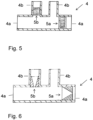
- FIG. 3 to 6 Preferred embodiments of a nasal cannula according to the invention are shown schematically in longitudinal section.
- the Figures 3 to 6 The nasal cannulas 4 shown also each have two connecting pieces 4a and two nasal prongs 4b. Furthermore, two areas with an increased flow resistance 5a and 5b are shown in the nasal cannulas 4. In each case, one such area 5a is shown in one of the connecting pieces 4a and one of the areas 5b is shown in one of the nasal prongs 4b.
- the areas identified by the reference symbols 5a and 5b represent alternative design variants.
- an area 5a with increased flow resistance is preferably provided in each of the connecting pieces 4a or, alternatively, an area 5b with increased flow resistance is provided in each of the nasal prongs 4b.
- the area with an increased flow resistance can, for example, be formed by an area with a reduced opening cross-section, such as an aperture (cf. Figure 3 ), through a sieve or a membrane filter (cf. Figure 4 ), through a porous depth filter made of sintered material or fiber material (cf. Figure 5 ) or through a nozzle (cf. Figure 6 ) are provided.
- a simple aperture, as used in Figure 3 can, under certain circumstances, lead to the escape of oxygen-enriched breathing gas in the form of a sharp or focused jet, which can cause unpleasant sensations in the patient's nose. It is therefore preferable to design the area with increased flow resistance in such a way that the exit speed of the breathing gas does not increase. This can be achieved, for example, by using many small openings (see. Figure 4 ) instead of a large opening.
- Plastic injection molding can also be used to create a labyrinth-like structure that slows down the flow of breathing gas. Filters, such as membrane filters or deep filters made of cellulose or plastic or porous materials such as sintered polyethylene or glass frit, have a similar effect.
- An area with increased flow resistance can also be created in the form of a nozzle (see. Figure 6 ) can lead to an expansion of the breathing gas jet.
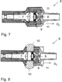
- FIG. 7 shows a longitudinal sectional view of a valve according to the invention in accordance with a preferred embodiment.
- the valve 6 is a valve which is suitable for mechanically automatically stopping the supply of the oxygen-enriched breathing gas in the event of an increase in the volume flow of oxygen-enriched breathing gas and/or a drop in pressure of the oxygen-enriched breathing gas.
- the valve 6 has a closure body 7 which in Figure 7 shown state due to the flow of oxygen illustrated by an arrow, if this suddenly increases, for example, is pressed to the right with its seal 9 against the valve seat 11, so that the valve 6 in the in Figure 7 shown state is open. With a smaller volume flow, however, the spring 8 holds the closure body 7 in the closed position to the left against the flow direction of the oxygen-enriched breathing gas.
- the open position shown represents the normal state of the valve with regular supply of oxygen-enriched breathing gas
- the closed position of the valve 6 is realized when, for example, at a volume flow of 5 l/min, there is an increase in the volume flow of at least 30%, preferably at least 20% and particularly preferably at least 10%.
- Such an increase in the volume flow is caused according to the invention by the flow resistance of the area with an increased flow resistance being increased under the influence of heat
- the Figures 3 to 6 shown structures of the respective areas 5a and 5b melt under the influence of heat or become deformed to such an extent that a measurable increase in the volume flow and/or a measurable pressure drop is caused.
- a device can be provided on the valve 6 which enables the closure body 7 to be fixed in the open position.
- two elastic regions 10 may be provided, onto which the user can press with two fingers, causing the elastomer 10 to swell into the interior of the valve housing, thereby holding the closing body 7 of the valve 6 in its current position.
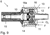
- a slidably arranged ring 16 may be provided which extends around a valve housing portion 12 and can slide over the valve housing portion 12 in the distal and proximal directions, as shown in Figure 9 is shown.
- a projection 13 or another device for limiting the displacement path of the ring 16 in the distal direction can be provided at the distal end of the valve housing section 12.
- proximal connection piece 15 of the valve 6 is now connected to a concentrator, for example, the user, when he grips the valve 6 at the ring 16, will exert a force acting in the proximal direction (see arrow) on the ring 16, which, due to the wedge-shaped proximal section 16a of the ring 16, leads to the balls 14 being pressed into the elastomer 10, so that a pre-swelling of the elastomer 10 into the interior of the valve housing holds the closing body 7 of the valve 6 in its current position.
- the valve 6 can also have a magnetic mechanism, by means of which the valve is pre-tensioned into the open position against the flow direction of the oxygen-enriched breathing gas.
- the valve can also be an electromagnetic or electromotive valve that is controlled by means of a combination of sensor and control.
Landscapes
- Health & Medical Sciences (AREA)
- Engineering & Computer Science (AREA)
- Public Health (AREA)
- Pulmonology (AREA)
- Emergency Medicine (AREA)
- General Health & Medical Sciences (AREA)
- Veterinary Medicine (AREA)
- Heart & Thoracic Surgery (AREA)
- Hematology (AREA)
- Life Sciences & Earth Sciences (AREA)
- Animal Behavior & Ethology (AREA)
- Anesthesiology (AREA)
- Biomedical Technology (AREA)
- Otolaryngology (AREA)
- General Engineering & Computer Science (AREA)
- Business, Economics & Management (AREA)
- Emergency Management (AREA)
- Mechanical Engineering (AREA)
- Respiratory Apparatuses And Protective Means (AREA)
Description
- Die vorliegende Erfindung betrifft eine Vorrichtung zur Versorgung eines Patienten mit sauerstoffangereichertem Atemgas mit einer Brandschutzeinrichtung.
- Patienten mit ausgeprägten Lungenfunktionsstörungen sind in ihrer Aktivität stark eingeschränkt, da sie häufig schon nach leichten körperlichen Belastungen Atemnot entwickeln. Die Lungenfunktionsstörungen können auch so ausgeprägt sein, dass die Patienten in Ruhe Atemnot verspüren. Sofern die Lungenfunktionsstörung nicht medikamentös zu lindern ist, z. B. durch Medikamente, die die Bronchien erweitern, bleibt nur die Möglichkeit, den Patienten mit einem erhöhten Sauerstoffanteil in der Atemluft zu versorgen, der dann auch bei eingeschränkter Lungenfunktion zu einer höheren Sauerstoffsättigung im Blut führt. Dadurch können die Patienten mit Hilfe von tragbaren Sauerstoffgeräten wieder aktiver werden oder, sofern sie dazu nicht in der Lage sind, kann zumindest die Atemnot gelindert werden.
- Eine solche Versorgung mit Sauerstoff erfolgt in der Regel mit einem Schlauchsystem, mit dem einem Patienten Sauerstoff oder sauerstoffangereicherte Luft zugeführt werden kann. Der Sauerstoff kann bereitgestellt werden aus Druckflaschen, Flüssigsauerstoffgefäßen (Dewar), aus Sauerstoffkonzentratoren oder -generatoren oder aus zentralen Sauerstoffversorgungsanlagen. Der Sauerstoff kann dem Patienten über eine sogenannte Nasenbrille, über eine Atemmaske (geschlossen oder offen) oder über einen Beatmungstubus durch Mund / Nase oder Tracheostoma zugeführt werden.
- Zahlreiche der sauerstoffbedürftigen Patienten leiden an einer sogenannten COPD, eine chronisch obstruktive Lungenerkrankung, die in der Regel durch langjähriges Rauchen ausgelöst wird. Ca. 20% der Patienten können es nicht unterlassen, trotz entsprechender Warnungen auch während der Sauerstoffbehandlung zu rauchen (vgl. West GA, Primeau P. Nonmedical hazards of long-term oxygen therapy. Respir Care. 1983; 28:906-12). Durch den Sauerstoff kommt es zu einer erheblichen Brandbeschleunigung, die Zigaretten können in Flammen aufgehen, dabei entzündet sich dann häufig auch die Kunststoff-Nasenbrille oder Atemmaske sowie die Kleidung oder die Bettwäsche des Patienten. Durch den nachströmenden Sauerstoff wird das Feuer erheblich beschleunigt und binnen kurzer Zeit kann das Bett des Patienten oder er selbst in hellen Flammen stehen. Todesfälle durch diese Brände sind berichtet worden (vgl. Morbidity and mortality weekly report. Fatal fires associated with smoking during long-term oxygen therapy. Maine, Massachussetts, New Hampshire, and Oklahoma. 2000-2007. MMWR. 2008; 57:852-854).
- Es sind bereits Vorrichtungen bekannt, in denen der Gasfluss bei Druckabfall im System unterbunden wird. So offenbart beispielsweise
US 6,269,811 B1 ein Druckunterstützungssystem, das auf eine Unterbrechung des Gasflusses abzielt, sobald ein primäres, druckerzeugendes System ausfällt.DE 29 29 163 A1 hingegen beschreibt ein Bedarfsatemventil, das an einer Gesichtsmaske angebracht ist und unter besonderen Bedingungen, beispielsweise wenn ein Druckabfall durch das Abnehmen der Maske vom Gesicht entsteht, schließen kann, um unnötige Gasverluste zu vermeiden. Diese Vorrichtungen bieten jedoch keine Lösung für das Problem der Flussunterbrechung bei Feuer. - Es gibt bereits verschiedene Systeme, den nachfließenden Sauerstoff zu stoppen und damit die Ausbreitung des Feuers zu verhindern oder zumindest zu vermindern. So beschreibt beispielsweise die
WO 2014/020334 A1 ein Ventil, das in den Zuleitungsschlauch eingebaut werden kann und das, wenn es von den Flammen erreicht wird, den Zustrom automatisch stoppt, so dass kein Sauerstoff mehr nachfließen kann. Dieses System hat allerdings den Nachteil, dass es in der Regel in das Ende des Sauerstoffschlauches eingebaut wird, wo dieser sich in zwei Schläuche aufteilt, die dann die sogenannte Nasenbrille bilden, über die der Patient den Sauerstoff bekommt. Das Feuer muss sich also erst vom primären Brandherd über diese beiden Schläuche bis zum Anschluss an den gemeinsamen Zuleitungsschlauch ausbreiten, um das Ventil zu aktivieren. Dadurch fließt unnötig lang Sauerstoff nach. Außerdem kann auch, da sich der Brand auch über die Bettwäsche und/oder Kleidung des Patienten ausbreitet, der Zuleitungsschlauch vor dem Ventil von den Flammen ergriffen werden, schmelzen und dadurch der Sauerstoffzustrom wieder freigegeben werden. -
EP 2 682 149 A2 beschreibt ein System, bei dem im Schlauch ein dünner Kupferdraht integriert ist, an dem eine Spannung liegt oder dessen Widerstand gemessen wird. Kommt es jetzt zum Entflammen des Schlauches, schmilzt dieser Kupferdraht durch und über ein entsprechendes Überwachungsgerät wird die Sauerstoffzufuhr unterbrochen. Diese Anordnung kann sicherlich deutlich früher als die inWO 2014/020334 A1 beschriebene den Zufluss von Sauerstoff unterbinden, sie ist aber sehr aufwendig in der Herstellung. Da ein geschlossener Stromkreis vorliegen muss, muss die Zuleitung zur Nasenbrille des Patienten über zwei Schläuche erfolgen, zwischen denen zuverlässige elektrische Kontakte bestehen müssen. Auch die elektrische Verbindung des Kupferdrahtes mit dem Überwachungsgerät ist aufwendig. -
DE 20 2012 009 706 U1 beschreibt ein entsprechendes System mit einem Lichtleiter an Stelle des Kupferdrahtes, was noch aufwändiger sein dürfte. -
US 5,927,312 beschreibt ein System mit einem sich selbst löschenden Schlauch, bei dem im Falle eines Brandes ein Verschluss ausgelöst wird, der den Gasstrom im Wesentlichen unterbinden soll. Dies wird durch eine Kombination verschiedener Materialien realisiert, wobei sich ein hitzeempfindliches Material ausdehnt, das an der gewünschten Verschlussstelle außen um die Leitung herum angebracht ist, bzw. zusammenzieht oder schmilzt, sofern es im Inneren der Leitung angebracht ist. Wie inUS 5,927,312 jedoch bereits erwähnt, würde das Anbringen dieses Systems in den Nasenzuführungen zu einer nicht erwünschten Zunahme von Material und Gewicht im Gesichtsbereich führen. Im Übrigen hat das beschriebene System die gleichen Nachteile wieWO 2014/020334 A1 . -
DE 20 2015 007 512 U1 beschreibt einen Atemluftschlauch, der mit nicht brennbarem Material beschichtet ist und sich daher nicht ohne weiteres entzünden lässt. Dieser Atemluftschlauch verhindert aber nicht den Nachstrom von Sauerstoff und kann das Entflammen der Zigarette und die daraus folgende sauerstoffbeschleunigte Entzündung von Kleidung und Bettwäsche nicht verhindern. - Es ist demnach eine Aufgabe der vorliegenden Erfindung, ein technisch einfaches und in der Herstellung preisgünstiges System bereitzustellen, das einen frühen und sicheren Stopp des nachströmenden Sauerstoffes gewährleistet.
- Diese Aufgabe wird mittels einer Vorrichtung zur Versorgung eines Patienten mit sauerstoffangereichertem Atemgas gemäß Anspruch 1 sowie durch ein Verfahren zum Betrieb einer solchen Vorrichtung nach Anspruch 14 gelöst. Bevorzugte Ausführungsformen der erfindungsgemäßen Vorrichtung und des erfindungsgemäßen Verfahrens werden in den abhängigen Ansprüchen beschrieben.
- Dementsprechend richtet sich die vorliegende Erfindung auf eine Vorrichtung zur Versorgung eines Patienten mit sauerstoffangereichertem Atemgas. Die Vorrichtung weist eine Einrichtung zur Bereitstellung von sauerstoffangereichertem Atemgas, eine mit der Einrichtung verbundene Zuführleitung, über die das sauerstoffangereicherte Atemgas von der Einrichtung an den Patienten zugeführt werden kann, und einen Detektor auf, der dazu geeignet ist, eine Zunahme des Volumenstroms von sauerstoffangereichertem Atemgas und/oder einen Druckabfall des sauerstoffangereicherten Atemgases zu detektieren. Die Vorrichtung ist dazu geeignet und dazu eingerichtet, die Zufuhr des sauerstoffangereicherten Atemgases im Falle einer Zunahme des Volumenstroms von sauerstoffangereichertem Atemgas und/oder eines Druckabfalls des sauerstoffangereicherten Atemgases zu unterbinden bzw. unterbrechen. Dabei weist die Zuführleitung einen patientennahen Bereich mit einem vergrößerten Strömungswiderstand auf, der derart beschaffen ist, dass der Strömungswiderstand unter Einwirkung von Hitze durch Schmelzen des Schlauches reduziert wird. Die Vorrichtung weist ferner ein Ventil auf, das die Zufuhr des sauerstoffangereicherten Atemgases im Falle einer Zunahme des Volumenstroms von sauerstoffangereichertem Atemgas und/oder eines Druckabfalls des sauerstoffangereicherten Atemgases unterbindet, wobei das Ventil dazu geeignet ist, mechanisch selbsttätig die Zufuhr des sauerstoffangereicherten Atemgases im Falle einer Zunahme des Volumenstroms von sauerstoffangereichertem Atemgas und/oder eines Druckabfalls des sauerstoffangereicherten Atemgases zu unterbinden.
- Mit anderen Worten liegt der Erfindung das Prinzip zugrunde, dass direkt am Abgabeort des Sauerstoffs bzw. der sauerstoffangereicherten Atemluft eine Flussrestriktion erfolgt (im einfachsten Falle beispielsweise durch eine Querschnittsverengung der Zuführleitung), was zu einer relativen Druckerhöhung im proximalen Bereich der Zuführleitung führt. Bei einem Feuer im Gesichtsbereich des Patienten, z.B. durch eine sich entflammende Zigarette, wird diese Flussrestriktion wieder aufgehoben, da der Bereich mit einem vergrößerten Strömungswiderstand derart beschaffen ist, dass der Strömungswiderstand unter Einwirkung von Hitze reduziert wird. So kann beispielsweise die Querschnittsverengung unter Einwirkung von Hitze aufschmelzen. Dies bewirkt eine Zunahme des Volumenstroms bzw. einen Druckabfall in der Zuführleitung, was wiederum dazu führt, dass die Zufuhr des sauerstoffangereicherten Atemgases unterbunden wird. Dies erfolgt dadurch, dass das Ventil geschlossen wird.
- Die erfindungsgemäße Vorrichtung ist technisch relativ einfach und daher kostengünstig in der Herstellung und garantiert einen frühzeitigen und sicheren Stopp der Sauerstoffzufuhr, da die Detektion des Feuers (über den Bereich mit einem vergrößerten Strömungswiderstand) patientennah erfolgt.
- Bei der Einrichtung zur Bereitstellung von sauerstoffangereichertem Atemgas kann es sich um eine Druckflasche, ein Flüssigsauerstoffgefäß (Dewar), einen Sauerstoffkonzentrator oder -generator oder eine zentrale Sauerstoffversorgungsanlage handeln. Die Einrichtung ist dazu geeignet, ein Atemgas mit gegenüber Umgebungsluft erhöhtem Sauerstoffanteil bereitzustellen. Gegebenenfalls kann das sauerstoffangereicherte Atemgas auch reiner Sauerstoff sein. Je nach Art und Funktionsweise der Einrichtung zur Bereitstellung von sauerstoffangereichertem Atemgas bietet sich für die Unterbindung bzw. Unterbrechung der Atemgaszufuhr bevorzugt ein Abschalten (z.B. Konzentrator) oder ein Schließen eines Ventils (z.B. Druckflasche) an. Ersteres ließe sich auch sehr einfach als Vorschaltgerät realisieren, in das der Stecker beispielsweise des Konzentrators eingesteckt wird. Dies hat den Vorteil, dass bereits existierende Konzentratoren ohne kompliziertes oder teures Nachrüsten mit der erfindungsgemäßen Vorrichtung verwendet werden können.
- Die Zuführleitung, über die das sauerstoffangereicherte Atemgas von der Einrichtung zur Bereitstellung von sauerstoffangereichertem Atemgas einem Patienten zugeführt werden kann, ist mit der Einrichtung zur Bereitstellung von sauerstoffangereichertem Atemgas direkt oder indirekt verbunden. Insbesondere kann eine Einrichtung zur Regelung des Zuführstroms und/oder des Drucks in der Zuführleitung vorhanden sein. Die Zuführleitung weist bevorzugt einen Zuführschlauch mit einer Nasenbrille oder einem Konnektor zur Verbindung mit einer Atemmaske oder einem Beatmungstubus auf. Bevorzugt ist der Bereich mit einem vergrößerten Strömungswiderstand am patientenseitigen Ende des Zuführschlauchs, an der Nasenbrille und/oder am Konnektor vorgesehen. Bevorzugt ist der Bereich mit einem vergrößerten Strömungswiderstand möglichst nah am Austrittsort des sauerstoffangereicherten Atemgases vorgesehen, da sich an diesem Austrittsort der Brand am schnellsten entwickelt. Bevorzugt ist der Abstand zwischen dem Bereich mit einem vergrößerten Strömungswiderstand und dem Austrittsort des sauerstoffangereicherten Atemgases kleiner als 10 cm, stärker bevorzugt kleiner als 5 cm und besonders bevorzugt kleiner als 3 cm.
- Gemäß einer ersten bevorzugten Variante, die nicht unter den Wortlaut der Ansprüche fällt, wird die Zunahme des Volumenstroms von sauerstoffangereichertem Atemgas und/oder der Druckabfall des sauerstoffangereicherten Atemgases in der Zuführleitung detektiert bzw. gemessen und die Einrichtung zur Bereitstellung von sauerstoffangereichertem Atemgas bzw. das Ventil mittels einer geeigneten Steuerung abgeschaltet bzw. geschlossen. Hierfür weist die Vorrichtung bevorzugt einen Detektor auf, der dazu geeignet ist, eine Zunahme des Volumenstroms von sauerstoffangereichertem Atemgas in der Zuführleitung und/oder einen Druckabfall des sauerstoffangereicherten Atemgases in der Zuführleitung zu detektieren. Der Detektor kann in der Zuführleitung oder an der Einrichtung zur Bereitstellung von sauerstoffangereichertem Atemgas vorgesehen sein. Die Vorrichtung weist ferner bevorzugt eine Steuerung auf, die dazu geeignet ist, das Ventil zu schließen und/oder die Einrichtung zur Bereitstellung von sauerstoffangereichertem Atemgas abzuschalten, falls der Detektor eine Zunahme des Volumenstroms von sauerstoffangereichertem Atemgas und/oder einen Druckabfall des sauerstoffangereicherten Atemgases detektiert. Bevorzugt ist der Detektor dazu geeignet, eine relative Zunahme des Volumenstroms von sauerstoffangereichertem Atemgas in der Zuführleitung um mindestens 50%, bevorzugt um mindestens 30%, stärker bevorzugt um mindestens 20%, besonders bevorzugt um mindestens 10% zu detektieren. Alternativ oder zusätzlich ist der Detektor bevorzugt dazu geeignet, einen relativen Druckabfall des sauerstoffangereicherten Atemgases in der Zuführleitung von mindestens 50%, bevorzugt von 30%, stärker bevorzugt von mindestens 20% und besonders bevorzugt von mindestens 10% zu detektieren.
- Bevorzugt ist die Steuerung dazu eingerichtet, im Normalbetrieb, bevorzugt nach einer vorbestimmten Zeitspanne nach dem Beginn der Bereitstellung von sauerstoffangereichertem Atemgas, mittels des Detektors den Volumenstrom von sauerstoffangereichertem Atemgas und/oder den Druck des sauerstoffangereicherten Atemgases zu messen und einen Schwellwert zu definieren. Die Steuerung ist ferner bevorzugt dazu eingerichtet, die Zufuhr des sauerstoffangereicherten Atemgases zu unterbinden, wenn eine prozentuale Mindestabweichung des gemessenen Volumenstroms von sauerstoffangereichertem Atemgas und/oder des gemessenen Drucks des sauerstoffangereicherten Atemgases vom Schwellwert ermittelt wird. Die prozentuale Mindestabweichung beträgt bevorzugt 50%, stärker bevorzugt 30%, noch stärker bevorzugt 20% und besonders bevorzugt 10%. Die vorbestimmte Zeitspanne beträgt bevorzugt mindestens 10 s, stärker bevorzugt mindestens 20 s, noch stärker bevorzugt mindestens 30 s und besonders bevorzugt mindestens 1 min. Dadurch wird sichergestellt, dass der Schwellwert erst dann bestimmt wird, wenn sich bereits ein Strömungsgleichgewicht eingestellt hat und idealerweise die Nasenbrille bereits am Patienten befestigt ist, so dass nachfolgend Abweichungen von diesem Normal- oder Schwellwert bestimmt werden können.
- Zusätzlich oder alternativ kann die Vorrichtung eine Einrichtung bzw. einen Mechanismus aufweisen, der dafür sorgt, dass die Atemgaszufuhr kurz unterbrochen wird, wenn die Zuführleitung mit der Einrichtung zur Bereitstellung von sauerstoffangereichertem Atemgas verbunden wird. Wenn der Anwender beispielsweise erst den Konzentrator anwirft und dann erst den die Zuführleitung an den Konzentrator anschließt, dann kann die Steuerung der Vorrichtung einen falschen Schwellwert einstellen. Durch die kurze Unterbrechung wird die Steuerung getriggert, einen neuen Schwellwert nach dem Verbinden der Zuführleitung mit dem Konzentrator zu bestimmen. Hierfür könnte beispielsweise der Schlauchanschluss der Zuführleitung axial geringgradig verschieblich sein, so dass beim Aufstecken und Abnehmen des Schlauches jeweils die Atemgaszufuhr unterbrochen wird oder die Fluss- bzw. Druckmessung neu ausgelöst wird.
- Gemäß einer zweiten, erfindungsgemäßen Variante ist das Ventil selbst dazu geeignet, mechanisch selbsttätig die Zufuhr des sauerstoffangereicherten Atemgases im Falle einer Zunahme des Volumenstroms von sauerstoffangereichertem Atemgas durch das Ventil und/oder eines Druckabfalls des sauerstoffangereicherten Atemgases am Ventil zu unterbinden. Bevorzugt weist das Ventil eine Feder oder einen Magneten auf, die/der das Ventil entgegen der Stromrichtung des sauerstoffangereicherten Atemgases in die Offenstellung vorspannt. Bevorzugt ist dabei die Federkonstante der Feder bzw. die Kraft des Magneten derart bemessen, dass das Ventil bei einem Volumenstrom von 5 l/min und einem schlagartigen Druckabfall von mindesten 50%, bevorzugt von mindestens 30%, besonders bevorzugt von mindestens 20% geschlossen wird.
- Der Bereich mit einem vergrößerten Strömungswiderstand kann grundsätzlich durch sehr unterschiedliche strukturelle Merkmale in allen möglichen Varianten bereitgestellt werden, solange er derart beschaffen ist, dass der Strömungswiderstand unter Einwirkung von Hitze reduziert wird. Darunter wird im Kontext der vorliegenden Erfindung verstanden, dass der Bereich mit einem vergrößerten Strömungswiderstand während einer gewissen Mindestdauer einer gewissen Mindesttemperatur ausgesetzt wird. Die Mindestdauer beträgt bevorzugt 10 Sek., stärker bevorzugt 5 Sek., noch stärker bevorzugt 3 Sek. und besonders bevorzugt 2 Sek. Die Mindesttemperatur beträgt bevorzugt 140°C, stärker bevorzugt 120°C und besonders bevorzugt 100°C. Dementsprechend ist es besonders bevorzugt, dass der Bereich mit einem vergrößerten Strömungswiderstand derart beschaffen ist, dass der Strömungswiderstand reduziert wird, wenn der Bereich mindestens 2 Sekunden lang einer Temperatur von mindestens 100°C ausgesetzt wird.
- Dabei soll der Strömungswiderstand des Bereichs unter Einwirkung von Hitze soweit reduziert werden, dass die dadurch verursachte Zunahme des Volumenstroms bzw. der dadurch verursachte Druckabfall von einem Detektor bzw. Sensor erfasst werden kann und/oder direkt zu einem Schließen des Ventils führt. Dementsprechend hängt die erfindungsgemäß notwendige Reduzierung des Strömungswiderstands von der Art des verwendeten Detektors bzw. von der Empfindlichkeit des Ventils ab sowie von den Bedingungen (Druck und Volumenstrom) ab, unter denen das Atemgas verabreicht wird.
- Letztere hängen unter anderem vom Patienten (manche Patienten werden mit einem Volumenstrom von z.B. 5 l/min, andere mit einem Volumenstrom von z.B. 3 l/min versorgt) und von der Art der Einrichtung zur Bereitstellung des angereicherten Atemgases ab.
- Es ist jedoch bevorzugt, dass der Bereich mit einem vergrößerten Strömungswiderstand einen Strömungswiderstand aufweist, der einer Blende mit einem lichten Durchmesser zwischen 0,1 mm und 4 mm, stärker bevorzugt zwischen 0,3 mm und 3 mm und besonders bevorzugt zwischen 0,5 mm und 2 mm entspricht. Ferner ist bevorzugt, dass der Bereich mit einem vergrößerten Strömungswiderstand einen Strömungswiderstand aufweist, der kleiner oder gleich dem Strömungswiederstand einer Blende mit einem lichten Durchmesser mit 2 mm, bevorzugt mit 1,5 mm und besonders bevorzugt mit 1 mm ist. Es ist ferner bevorzugt, dass, beispielsweise im Falle mehrerer Öffnungen mit reduzierter Querschnittsfläche, die größte Öffnung in dem Bereich mit einem vergrößerten Strömungswiderstand eine Querschnittsfläche von maximal 10 mm2, bevorzugt von maximal 5 mm2, stärker bevorzugt von maximal 3 mm2, noch stärker bevorzugt von maximal 2 mm2 und besonders bevorzugt von maximal 1 mm2 aufweist. Ferner ist bevorzugt, dass der Bereich mit einem vergrößerten Strömungswiderstand eine Querschnittsfläche aufweist, die maximal 40%, bevorzugt maximal 30%, stärker bevorzugt maximal 20%, noch stärker bevorzugt maximal 15% und besonders bevorzugt maximal 10% der maximalen Querschnittsfläche der restlichen Zuführleitung beträgt. Es ist ferner bevorzugt, dass der Bereich mit einem vergrößerten Strömungswiderstand einen Strömungswiderstand aufweist, der gegenüber dem Strömungswiderstand der restlichen Zuführleitung bei einem Volumenstrom von 5 l/min um mindestens 10%, bevorzugt um mindestens 20%, stärker bevorzugt um mindestens 30%, noch stärker bevorzugt um mindestens 50% und besonders bevorzugt um mindestens 100% erhöht ist. Je nachdem, ob eine laminare oder turbulente Strömung vorliegt, kann der Strömungswiderstand auch um einen Faktor von mindestens 2, bevorzugt mindestens 3, stärker bevorzugt mindestens 5 und besonders bevorzugt mindestens 8 erhöht werden. Es ist ferner bevorzugt, dass der Bereich mit einem vergrößerten Strömungswiderstand derart beschaffen ist, dass eine Entfernung und/oder Zerstörung des Bereichs bei einem Volumenstrom von 5 l/min zu einem Druckabfall in der Zuführleitung von mindestens 0,05 bar, stärker bevorzugt von mindestens 0,1 bar und besonders bevorzugt von mindestens 0,2 bar führt.
- Derartige Bereiche mit einem vergrößerten Strömungswiderstand können auf unterschiedliche Art und Weise realisiert werden. Beispielsweise kann der Bereich mit einem vergrößerten Strömungswiderstand eines oder einer Kombination der folgenden Elemente aufweisen: Bereich mit reduziertem Öffnungsquerschnitt, Blende, Düse, mehrere Öffnungen mit reduzierter Querschnittsfläche, labyrinthartige Struktur, Sieb, Filter wie z.B. Sinterfilter, Tiefenfilter aus Zellulose oder Kunststofffasern oder Membranfilter.
- Die Reduktion des Strömungswiderstands unter Einwirkung von Hitze kann dabei mittels unterschiedlicher Wirkmechanismen erzielt werden. Beispielsweise kann der Bereich aus einem Material bestehen, das unter Einwirkung von Hitze seine Stabilität verliert und/oder schmilzt. So kann der Bereich mit einem erhöhten Strömungswiderstand beispielsweise aus Polyethylen mit einer Schmelztemperatur von ca. 100°C gefertigt sein. Unter Einwirkung von Hitze schmilzt dann beispielsweise der Bereich mit erhöhtem Öffnungsquerschnitt, die Düse, etc., sodass der Strömungswiderstand in dem Bereich reduziert wird und bei vollständigem Schmelzen dem Strömungswiderstand in der restlichen Zuführleitung entspricht. Alternativ könnte die Reduktion des Strömungswiderstands unter Einwirkung von Hitze auch durch ein leicht brennbares Material bewirkt werden. So könnte beispielsweise ein Filter aus Zellulose in der Zuführleitung verbrennen und so den Strömungswiderstand reduzieren.
- Das Ventil ist bevorzugt in oder an der Einrichtung zur Bereitstellung von sauerstoffangereichertem Atemgas oder in der Zuleitung vorgesehen.
- Bevorzugt ist die Vorrichtung ferner dazu geeignet, einen Alarm auszulösen, wenn das Ventil die Zufuhr des sauerstoffangereicherten Atemgases unterbindet. Dieser Alarm kann beispielsweise durch die Steuerung ausgelöst werden, die das Ventil schließt. Alternativ könnte mit der Ventilauslösung beispielsweise ein elektrischer Kontakt betätigt werden, der zur Alarmierung durch einen Gerätealarm oder einen externen Alarm führt.
- Die Vorrichtung weist bevorzugt ferner eine Quelle für nichtbrennbares Gas, insbesondere Stickstoff, Edelgas und/oder Kohlendioxid, auf, wobei die Vorrichtung dazu geeignet ist, die Zuführleitung mit dem nichtbrennbaren Gas zu fluten, wenn das Ventil die Zufuhr des sauerstoffangereicherten Atemgases unterbindet. Hierfür kann beispielsweise ein Zweiwegeventil oder ein Bypass distal vom Ventil vorgesehen sein.
- Wenn das erfindungsgemäße Ventil bzw. dessen Steuerung immer dann anspricht, wenn der Volumenstrom von sauerstoffangereichertem Atemgas zunimmt oder ein Druckabfall erfolgt, so kann es passieren, dass beispielsweise beim Anfahren des Konzentrators oder beim Verbinden der Zuleitung mit der Einrichtung zur Bereitstellung von sauerstoffangereichertem Atemgas ein schneller Druckanstieg erfolgt, der dazu führen könnte, dass das Ventil ungewollt geschlossen wird. Daher ist bevorzugt eine Einrichtung vorgesehen, die ein ungewolltes Schließen des Ventils verhindert. Beispielsweise könnte bei einem elektronisch gesteuerten Ventil dafür gesorgt werden, dass die Steuerung des Ventils erst mit einer Zeitverzögerung von beispielsweise wenigen Sekunden nach dem Anfahren des Konzentrators und/oder Verbindung der Zuleitung mit der Einrichtung zur Bereitstellung von sauerstoffangereichertem Atemgas eingeschaltet wird.
- Nachdem sich die Steuerung eingeschaltet hat, misst sie zunächst den bestehenden Druck oder Flow bzw. Volumenstrom, um danach auf Druckabfall oder Flowzunahme (bzw. Volumenstromzunahme) reagieren zu können.
- Im Falle eines Ventils, das dazu geeignet ist, mechanisch selbsttätig die Zufuhr des sauerstoffangereicherten Atemgases zu unterbinden, kann das Ventil bevorzugt manuell in der Offenstellung fixiert werden. Beispielweise könnte das Ventilgehäuse zwei elastische Bereiche aufweisen, auf die der Anwender mit zwei Fingern drücken kann und die durch das Vorquellen des Elastomers in das Innere des Ventilgehäuses den Schließkörper des Ventils festhalten bzw. fixieren und nach dem Loslassen wieder freigeben. So kann der Anwender das Ventil in der Offenstellung fixieren, während er den Konzentrator startet, und anschließend das Ventil wieder freigeben. Wenn die Offenhaltung des Ventils magnetisch erfolgt, könnte der Schließkörper des Ventils auch berührungslos durch einen verschieblichen Eisenring in der Offenstellung gehalten werden.
- Bei dem Ventil kann es sich beispielsweise um ein mechanisches Flow-Stopp-Ventil handeln, das beispielsweise als Einmalprodukt in das patientenferne Ende der Zuführleitung integriert ist. Alternativ könnte das Flow-Stopp-Ventil als separates, wiederverwendbares Teil direkt an die Einrichtung zur Bereitstellung von sauerstoffangereichertem Atemgas angeschlossen oder in diese integriert sein. Das Ventil kann auch verstellbar sein, um die Auslöseschwelle an den eingestellten Volumenstrom anzupassen. Diese Anpassung kann auch automatisch erfolgen. Wird das Ventil durch eine Steuerung gesteuert, so kann es sich bei dem Ventil beispielsweise um ein elektromagnetisches oder elektromotorisches Ventil handeln.
- Die vorliegende Erfindung betrifft ferner ein Verfahren zum Betrieb eine Vorrichtung wie oben beschrieben. Das Verfahren weist die folgenden Schritte auf:
- Aktivierung der Bereitstellung von sauerstoffangereichertem Atemgas durch Einschalten der Einrichtung zur Bereitstellung von sauerstoffangereichertem Atemgas und/oder Öffnen eines Ventils,
- Messen des Volumenstroms von sauerstoffangereichertem Atemgas und/oder des Druck des sauerstoffangereicherten Atemgases und Definieren eines Schwellwerts auf Basis der Messung, wobei das Messen nach einer vorbestimmten Zeitspanne nach der Aktivierung erfolgt,
- kontinuierliches oder wiederholtes Messen des Volumenstroms von sauerstoffangereichertem Atemgas und/oder des Druck des sauerstoffangereicherten Atemgases, und
- Deaktivierung der Bereitstellung von sauerstoffangereichertem Atemgas durch mechanisch selbsttätiges Schließen des Ventils, wenn eine prozentuale Mindestabweichung des gemessenen Volumenstroms von sauerstoffangereichertem Atemgas und/oder des gemessenen Drucks des sauerstoffangereicherten Atemgases vom Schwellwert ermittelt wird.
- Im Kontext des erfindungsgemäßen Verfahrens können alle oben im Kontext mit der erfindungsgemäßen Vorrichtung beschriebenen bevorzugten Merkmale zum Einsatz kommen. Insbesondere beträgt die prozentuale Mindestabweichung bevorzugt 50%, stärker bevorzugt 30%, noch stärker bevorzugt 20% und besonders bevorzugt 10%. Die vorbestimmte Zeitspanne beträgt bevorzugt mindestens 10 s, stärker bevorzugt mindestens 20 s, noch stärker bevorzugt mindestens 30 s und besonders bevorzugt mindestens 1 min.
- Nachfolgend werden bevorzugte Ausführungsformen der vorliegenden Erfindung unter Bezugnahme auf die Figuren näher beschrieben. Es zeigen:
-
Fig. 1 in perspektivischer Ansicht eine Zuführleitung mit Nasenbrille; -
Fig. 2 in perspektivischer Ansicht die Nasenbrille gemäßFig. 1 ; -
Fig. 3 eine Längsschnittansicht durch eine erfindungsgemäße Nasenbrille gemäß einer bevorzugten Ausführungsform; -
Fig. 4 eine Längsschnittansicht durch eine erfindungsgemäße Nasenbrille gemäß einer bevorzugten Ausführungsform; -
Fig. 5 eine Längsschnittansicht durch eine erfindungsgemäße Nasenbrille gemäß einer bevorzugten Ausführungsform; -
Fig. 6 eine Längsschnittansicht durch eine Nasenbrille gemäß einer bevorzugten Ausführungsform; -
Fig. 7 eine Längsschnittansicht durch ein erfindungsgemäßes Ventil gemäß einer bevorzugten Ausführungsform; -
Fig. 8 eine Längsschnittansicht durch ein erfindungsgemäßes Ventil gemäß einer bevorzugten Ausführungsform; und -
Fig. 9 eine Längsschnittansicht durch ein erfindungsgemäßes Ventil gemäß einer bevorzugten Ausführungsform. -
Figur 1 zeigt in perspektivischer Ansicht eine Zuführleitung 1, über die das sauerstoffangereicherte Atemgas von einer Einrichtung zur Bereitstellung von sauerstoffangereichertem Atemgas (nicht dargestellt) einem Patienten zugeführt werden kann. Die Zuführleitung 1 weist einen Zuführschlauch 2 mit einer Nasenbrille 4 und einem Konnektor 3 auf, mithilfe dessen die Zuführleitung mit der Einrichtung zur Bereitstellung von sauerstoffangereichertem Atemgas verbunden werden kann. Solche Einrichtungen zur Bereitstellung von sauerstoffangereichertem Atemgas sind aus dem Stand der Technik bekannt und bedürfen keiner näheren Beschreibung. -
Figur 2 zeigt die Nasenbrille 4 gemäßFigur 1 nochmals in einer vergrößerten perspektivischen Ansicht. Die Nasenbrille 4 weist zwei Anschlussstücke 4a auf, mittels derer die Nasenbrille 4 mit dem Zuführschlauch 2 verbunden werden kann. Ferner weist die Nasenbrille 4 zwei Nasenstutzen 4b auf, die in die Nasenlöcher eines Patienten eingeführt werden können. - In den
Figuren 3 bis 6 sind jeweils in Längsschnittansicht bevorzugte Ausführungsformen einer erfindungsgemäßen Nasenbrille schematisch dargestellt. Die in denFiguren 3 bis 6 gezeigten Nasenbrillen 4 weisen ebenfalls jeweils zwei Anschlussstücke 4a und zwei Nasenstutzen 4b auf. Ferner sind in den Nasenbrillen 4 jeweils zwei Bereiche mit einem vergrößerten Strömungswiderstand 5a und 5b dargestellt. Dabei ist jeweils ein solcher Bereich 5a in einem der Anschlussstücke 4a gezeigt und einer der Bereiche 5b in einem der Nasenstutzen 4b gezeigt. Die durch die Bezugszeichen 5a und 5b gekennzeichneten Bereiche stellen dabei alternative Ausführungsvarianten dar. In den tatsächlichen Ausführungsformen der Nasenbrille 4 ist bevorzugt in jedem der Anschlussstücke 4a ein Bereich 5a mit vergrößertem Strömungswiderstand vorgesehen oder alternativ in jedem der Nasenstutzen 4b ein Bereich 5b mit vergrößertem Strömungswiderstand vorgesehen. Der Bereich mit einem vergrößertem Strömungswiderstand kann dabei beispielsweise durch einen Bereich mit reduziertem Öffnungsquerschnitt wie z.B. eine Blende (vgl.Figur 3 ), durch ein Sieb oder einen Membranfilter (vgl.Figur 4 ), durch einen porösen Tiefenfilter aus Sintermaterial oder Fasermaterial (vgl.Figur 5 ) oder durch eine Düse (vgl.Figur 6 ) bereitgestellt werden. - Eine einfache Blende, wie sie in
Figur 3 dargestellt ist, kann unter Umständen zu einem Austritt von sauerstoffangereichertem Atemgas in Form eines scharfen oder fokussierten Strahls führen, was in der Nase des Patienten unangenehme Empfindungen auslösen kann. Es ist daher bevorzugt, den Bereich mit vergrößertem Strömungswiderstand derart auszubilden, dass es nicht zu einer Erhöhung der Austrittsgeschwindigkeit des Atemgases kommt. Dies kann beispielsweise durch viele kleine Öffnungen (vgl.Figur 4 ) anstelle einer großen Durchtrittsöffnung bewerkstelligt werden. Mithilfe von Kunststoffspritzguss kann auch eine labyrinthartige Struktur erzeugt werden, die zu einer entsprechenden Abbremsung des Atemgasstroms führt. Auch Filter, beispielsweise Membranfilter oder Tiefenfilter aus Zellulose oder Kunststoff oder aus porösen Materialien wie z.B. gesintertem Polyethylen oder einer Glasfritte, haben einen ähnlichen Effekt. Ebenso kann ein Bereich mit erhöhtem Strömungswiderstand in Form einer Düse (vgl.Figur 6 ) zu einer Aufweitung des Atemgasstrahls führen. -
Figur 7 zeigt in einer Längsschnittansicht ein erfindungsgemäßes Ventil gemäß einer bevorzugten Ausführungsform. Bei dem Ventil 6 handelt es sich um ein Ventil, das dazu geeignet ist, mechanisch selbsttätigt die Zufuhr des sauerstoffangereicherten Atemgases im Falle einer Zunahme des Volumenstroms von sauerstoffangereichertem Atemgas und/oder eines Druckabfalls des sauerstoffangereicherten Atemgases zu unterbinden. Das Ventil 6 weist einen Verschlusskörper 7 auf, der im inFigur 7 dargestellten Zustand aufgrund des mittels eines Pfeils illustrierten Stroms von Sauerstoff, wenn dieser beispielsweise plötzlich zunimmt, nach rechts mit seiner Dichtung 9 gegen den Ventilsitz 11 gedrückt wird, sodass das Ventil 6 im inFigur 7 gezeigten Zustand geöffnet ist. Bei einem kleineren Volumenstrom hingegen hält die Feder 8 den Verschlusskörper 7 entgegen der Stromrichtung des sauerstoffangereicherten Atemgases nach links in der geschlossenen Stellung. Die inFigur 7 gezeigte Offenstellung stellt gewissermaßen den Normalzustand des Ventils bei regulärer Zufuhrleistung von sauerstoffangereichertem Atemgas dar, wohingegen die geschlossene Stellung des Ventils 6 dann realisiert wird, wenn beispielsweise bei einem Volumenstrom von 5 l/min eine Zunahme des Volumenstroms um mindestens 30%, bevorzugt um mindestens 20% und besonders bevorzugt um mindestens 10% erfolgt. Eine solche Zunahme des Volumenstroms wird erfindungsgemäß dadurch verursacht, dass der Strömungswiderstand des Bereichs mit einem vergrößerten Strömungswiderstand unter Einwirkung von Hitze reduziert wird. Beispielsweise können die in denFiguren 3 bis 6 dargestellten Strukturen der jeweiligen Bereiche 5a und 5b unter Einwirkung von Hitze abschmelzen oder soweit deformiert werden, dass ein messbarer Anstieg des Volumenstroms und/oder ein messbarer Druckabfall verursacht wird. - Um zu verhindern, dass das Ventil beispielsweise beim Einschalten des Konzentrators oder beim Verbinden der Zuleitung mit dem Konzentrator wegen eines dadurch verursachten Druckanstiegs ungewollt selbsttätig schließt, kann eine Einrichtung am Ventil 6 vorgesehen sein, die es ermöglicht, den Verschlusskörper 7 in der Offenstellung zu fixieren. Beispielsweise können, wie dies schematisch in
Figur 8 dargestellt ist, zwei elastische Bereiche 10 (oder eine ringförmige Struktur aus einem Elastomer) vorgesehen sein, auf die der Anwender mit zwei Fingern drücken kann, was ein Vorquellen des Elastomers 10 in das Innere des Ventilgehäuses bewirkt, wodurch der Schließkörper 7 des Ventils 6 in seiner aktuellen Position gehalten wird. - Zusätzlich oder alternativ kann ein verschiebbar angeordneter Ring 16 vorgesehen sein, der sich um einen Ventilgehäuseabschnitt 12 herum erstreckt und in distaler und proximaler Richtung über den Ventilgehäuseabschnitt 12 gleiten kann, wie dies in
Figur 9 dargestellt ist. Am distalen Ende des Ventilgehäuseabschnitts 12 kann ein Vorsprung 13 oder eine andere Einrichtung zur Begrenzung des Verschiebewegs des Rings 16 in distaler Richtung vorgesehen sein. Wird nun das proximale Anschlussstück 15 des Ventils 6 mit z.B. einem Konzentrator verbunden, so wird der Anwender, wenn er das Ventil 6 am Ring 16 greift, eine in proximaler Richtung wirkende Kraft (vgl. Pfeil) auf den Ring 16 ausüben, die wegen des keilförmigen proximalen Abschnitts 16a des Rings 16 dazu führt, dass die Kugeln 14 in das Elastomer 10 gedrückt werden, so dass ein Vorquellen des Elastomers 10 in das Innere des Ventilgehäuses den Schließkörper 7 des Ventils 6 in seiner aktuellen Position hält. - Anstelle der Feder 8 kann das Ventil 6 auch einen magnetischen Mechanismus aufweisen, mithilfe dessen das Ventil entgegen der Stromrichtung des sauerstoffangereicherten Atemgases in die Offenstellung vorgespannt wird. Ferner kann das Ventil auch ein elektromagnetisches oder elektromotorisches Ventil sein, das mittels einer Kombination aus Sensor und Steuerung kontrolliert wird.
Claims (15)
- Vorrichtung zur Versorgung eines Patienten mit sauerstoffangereichertem Atemgas, mit:einer Einrichtung zur Bereitstellung von sauerstoffangereichertem Atemgas;einer mit der Einrichtung verbundenen Zuführleitung (1), über die das sauerstoffangereicherte Atemgas von der Einrichtung einem Patienten zugeführt werden kann; undeinem Detektor, der dazu geeignet ist, eine Zunahme des Volumenstroms von sauerstoffangereichertem Atemgas und/oder einen Druckabfall des sauerstoffangereicherten Atemgases zu detektieren;wobei die Vorrichtung dazu geeignet ist, die Zufuhr des sauerstoffangereicherten Atemgases im Falle einer Zunahme des Volumenstroms von sauerstoffangereichertem Atemgas und/oder eines Druckabfalls des sauerstoffangereicherten Atemgases zu unterbinden, undwobei die Zuführleitung (1) einen patientennahen Bereich (5a; 5b) mit einem gegenüber dem Strömungswiderstand der restlichen Zuführleitung vergrößerten Strömungswiderstand aufweist, der derart beschaffen ist, dass der Strömungswiderstand unter Einwirkung von Hitze reduziert wird;ferner mit einem Ventil (6), das die Zufuhr des sauerstoffangereicherten Atemgases im Falle einer Zunahme des Volumenstroms von sauerstoffangereichertem Atemgas und/oder eines Druckabfalls des sauerstoffangereicherten Atemgases unterbindet, wobei das Ventil (6) dazu geeignet ist, mechanisch selbsttätig die Zufuhr des sauerstoffangereicherten Atemgases im Falle einer Zunahme des Volumenstroms von sauerstoffangereichertem Atemgas und/oder eines Druckabfalls des sauerstoffangereicherten Atemgases zu unterbinden.
- Vorrichtung nach Anspruch 1, ferner mit einer Steuerung, die dazu geeignet ist, die Einrichtung zur Bereitstellung von sauerstoffangereichertem Atemgas abzuschalten und/oder ein Ventil zu schließen, falls der Detektor eine Zunahme des Volumenstroms von sauerstoffangereichertem Atemgas und/oder einen Druckabfall des sauerstoffangereicherten Atemgases detektiert, wobei die Steuerung bevorzugt dazu eingerichtet ist, im Normalbetrieb, bevorzugt nach einer vorbestimmten Zeitspanne nach dem Beginn der Bereitstellung von sauerstoffangereichertem Atemgas, mittels des Detektors den Volumenstrom von sauerstoffangereichertem Atemgas und/oder den Druck des sauerstoffangereicherten Atemgases zu messen und einen Schwellwert zu definieren.
- Vorrichtung nach Anspruch 2, wobei die Steuerung dazu eingerichtet ist, die Zufuhr des sauerstoffangereicherten Atemgases zu unterbinden, wenn eine prozentuale Mindestabweichung des gemessenen Volumenstroms von sauerstoffangereichertem Atemgas und/oder des gemessenen Drucks des sauerstoffangereicherten Atemgases vom Schwellwert ermittelt wird, wobei bevorzugt die prozentuale Mindestabweichung 30%, stärker bevorzugt 20% und besonders bevorzugt 10% beträgt.
- Vorrichtung nach einem der vorigen Ansprüche, wobei der Detektor dazu geeignet ist, eine relative Zunahme des Volumenstroms von sauerstoffangereichertem Atemgas um 30%, bevorzugt um 20%, besonders bevorzugt um 10% und/oder einen relativen Druckabfall des sauerstoffangereicherten Atemgases von 30%, bevorzugt von 20%, besonders bevorzugt von 10% zu detektieren.
- Vorrichtung nach einem der vorigen Ansprüche, wobei das Ventil (6) in oder an der Einrichtung zur Bereitstellung von sauerstoffangereichertem Atemgas oder in der Zuleitung (1) vorgesehen ist, wobei das Ventil (6) bevorzugt eine Feder (8) oder einen Magneten aufweist, die/der das Ventil (6) entgegen der Stromrichtung des sauerstoffangereicherten Atemgases in die Offenstellung vorspannt, wobei die Federkonstante der Feder (8) oder die Kraft des Magneten bevorzugt derart bemessen ist, dass das Ventil (6) bei einem Volumenstrom von 5 l/min und einem Druckabfall von mindestens 30%, bevorzugt von mindestens 20%, besonders bevorzugt von mindestens 10% geschlossen wird.
- Vorrichtung nach einem der vorigen Ansprüche, wobei das Ventil (6) einen Verschlusskörper (7) und eine Einrichtung aufweist, die dazu geeignet ist, den Verschlusskörper manuell in der Offenstellung des Ventils zu fixieren.
- Vorrichtung nach einem der vorigen Ansprüche, wobei der Bereich (5a; 5b) mit einem vergrößerten Strömungswiderstand einen Strömungswiderstand aufweist, der einer Blende mit einem lichten Durchmesser zwischen 0,1 mm und 4 mm, bevorzugt zwischen 0,3 mm und 3 mm und besonders bevorzugt zwischen 0,5 mm und 2 mm entspricht und/oder der kleiner oder gleich dem Strömungswiederstand einer Blende mit einem lichten Durchmesser mit 2 mm, bevorzugt mit 1,5 mm und besonders bevorzugt mit 1 mm ist.
- Vorrichtung nach einem der vorigen Ansprüche, wobei die größte Öffnung in dem Bereich (5a; 5b) mit einem vergrößerten Strömungswiderstand eine Querschnittsfläche von maximal 10 mm2, bevorzugt von maximal 5 mm2, stärker bevorzugt von maximal 3 mm2, noch stärker bevorzugt von maximal 2 mm2 und besonders bevorzugt von maximal 1 mm2 aufweist und/oder wobei der Bereich (5a; 5b) mit einem vergrößerten Strömungswiderstand eine Querschnittsfläche aufweist, die maximal 40%, bevorzugt maximal 30%, stärker bevorzugt maximal 20%, noch stärker bevorzugt maximal 15% und besonders bevorzugt maximal 10% der maximalen Querschnittsfläche der restlichen Zuführleitung beträgt.
- Vorrichtung nach einem der vorigen Ansprüche, wobei der Bereich (5a; 5b) mit einem vergrößerten Strömungswiderstand einen Strömungswiderstand aufweist, der gegenüber dem Strömungswiderstand der restlichen Zuführleitung bei einem Volumenstrom von 5 l/min um mindestens 10%, bevorzugt um mindestens 20%, stärker bevorzugt um mindestens 30%, noch stärker bevorzugt um mindestens 50% und besonders bevorzugt um mindestens 100% erhöht ist.
- Vorrichtung nach einem der vorigen Ansprüche, wobei der Bereich (5a; 5b) mit einem vergrößerten Strömungswiderstand derart beschaffen ist, dass eine Entfernung und/oder Zerstörung des Bereichs bei einem Volumenstrom von 5 l/min zu einem Druckabfall in der Zuführleitung von mindestens 0,05 bar, bevorzugt von mindestens 0,1 bar und besonders bevorzugt von mindestens 0,2 bar führt.
- Vorrichtung nach einem der vorigen Ansprüche, wobei der Bereich (5a; 5b) mit einem vergrößerten Strömungswiderstand eines oder eine Kombination der folgenden Elemente aufweist: Bereich mit reduziertem Öffnungsquerschnitt, Blende, Düse, mehrere Öffnungen mit reduzierter Querschnittsfläche, labyrinthartige Struktur, Sieb, Filter wie z.B. Sinterfilter, Tiefenfilter aus Zellulose oder Kunststofffasern oder Membranfilter.
- Vorrichtung nach einem der vorigen Ansprüche, wobei die Zuführleitung (1) einen Zuführschlauch (2) mit einer Nasenbrille (4) oder einem Konnektor zur Verbindung mit einer Atemmaske oder einem Beatmungstubus aufweist, wobei der Bereich (5a; 5b) mit einem vergrößerten Strömungswiderstand am patientenseitigen Ende des Zuführschlauchs (1), an der Nasenbrille (4) und/oder am Konnektor vorgesehen ist.
- Vorrichtung nach einem der vorigen Ansprüche, ferner mit einer Quelle für nicht brennbares Gas, insbesondere Stickstoff, Edelgas und/oder Kohlendioxid, wobei die Vorrichtung dazu geeignet ist, die Zuführleitung mit dem nicht brennbaren Gas zu fluten, wenn die Zufuhr des sauerstoffangereicherten Atemgases unterbunden wird.
- Verfahren zum Betrieb einer Vorrichtung nach einem der vorigen Ansprüche mit den folgenden Schritten:Aktivierung der Bereitstellung von sauerstoffangereichertem Atemgas durch Einschalten der Einrichtung zur Bereitstellung von sauerstoffangereichertem Atemgas und/oder Öffnen eines Ventils,Messen des Volumenstroms von sauerstoffangereichertem Atemgas und/oder des Drucks des sauerstoffangereicherten Atemgases und Definieren eines Schwellwerts auf Basis der Messung, wobei das Messen nach einer vorbestimmten Zeitspanne nach der Aktivierung erfolgt,kontinuierliches oder wiederholtes Messen des Volumenstroms von sauerstoffangereichertem Atemgas und/oder des Drucks des sauerstoffangereicherten Atemgases, undDeaktivierung der Bereitstellung von sauerstoffangereichertem Atemgas durch mechanisch selbsttätiges Schließen des Ventils, wenn eine prozentuale Mindestabweichung des gemessenen Volumenstroms von sauerstoffangereichertem Atemgas und/oder des gemessenen Drucks des sauerstoffangereicherten Atemgases vom Schwellwert ermittelt wird.
- Verfahren nach Anspruch 14, wobei die prozentuale Mindestabweichung 30%, bevorzugt 20% und besonders bevorzugt 10% beträgt.
Applications Claiming Priority (3)
| Application Number | Priority Date | Filing Date | Title |
|---|---|---|---|
| DE102017001925 | 2017-03-02 | ||
| DE102017002544.4A DE102017002544A1 (de) | 2017-03-02 | 2017-03-15 | Vorrichtung zum Brandschutz bei der Therapie mit sauerstoffangereicherten Atemgasen |
| PCT/EP2018/055107 WO2018158396A1 (de) | 2017-03-02 | 2018-03-01 | Vorrichtung zum brandschutz bei der therapie mit sauerstoffangereicherten atemgasen |
Publications (2)
| Publication Number | Publication Date |
|---|---|
| EP3589347A1 EP3589347A1 (de) | 2020-01-08 |
| EP3589347B1 true EP3589347B1 (de) | 2025-02-19 |
Family
ID=63170950
Family Applications (1)
| Application Number | Title | Priority Date | Filing Date |
|---|---|---|---|
| EP18709517.9A Active EP3589347B1 (de) | 2017-03-02 | 2018-03-01 | Vorrichtung zum brandschutz bei der therapie mit sauerstoffangereicherten atemgasen |
Country Status (3)
| Country | Link |
|---|---|
| EP (1) | EP3589347B1 (de) |
| DE (1) | DE102017002544A1 (de) |
| WO (1) | WO2018158396A1 (de) |
Families Citing this family (2)
| Publication number | Priority date | Publication date | Assignee | Title |
|---|---|---|---|---|
| CN112007247B (zh) * | 2019-05-28 | 2023-04-25 | 上海潓美医疗科技有限公司 | 可配戴的呼吸管路系统及具有呼吸管路系统的呼吸设备 |
| CA3076157A1 (en) * | 2020-03-16 | 2021-09-16 | Rodney HERRING | Mask for protecting a user from airborne pathogens |
Citations (1)
| Publication number | Priority date | Publication date | Assignee | Title |
|---|---|---|---|---|
| WO2012001951A1 (ja) * | 2010-06-29 | 2012-01-05 | テルモ株式会社 | 過熱検知アダプタおよび過熱検知アダプタユニットならびに過熱検知アダプタを有する酸素濃縮装置 |
Family Cites Families (6)
| Publication number | Priority date | Publication date | Assignee | Title |
|---|---|---|---|---|
| CA1129303A (en) | 1978-07-19 | 1982-08-10 | Figgie International Inc. | Pressure-demand breathing apparatus with automatic air shut-off |
| US5927312A (en) | 1998-02-27 | 1999-07-27 | Dryden; Paul E. | Method and apparatus for extinguishing combustion within combustible tubing |
| US6269811B1 (en) | 1998-11-13 | 2001-08-07 | Respironics, Inc. | Pressure support system with a primary and a secondary gas flow and a method of using same |
| DE102012013055A1 (de) | 2012-07-02 | 2014-01-02 | Luchs Medizin Gmbh & Co. Kg | Sauerstoffgerät sowie Atemluftschlauch und Brandschutzmodul dafür |
| GB2504553A (en) | 2012-08-03 | 2014-02-05 | Bpr Medical Ltd | Flexible Medical Tubing Fire Safety Valve |
| DE202015007512U1 (de) | 2015-10-30 | 2016-01-07 | Norbert Neubauer | Atemluftschlauch mit Brandschutz |
-
2017
- 2017-03-15 DE DE102017002544.4A patent/DE102017002544A1/de active Pending
-
2018
- 2018-03-01 WO PCT/EP2018/055107 patent/WO2018158396A1/de not_active Ceased
- 2018-03-01 EP EP18709517.9A patent/EP3589347B1/de active Active
Patent Citations (1)
| Publication number | Priority date | Publication date | Assignee | Title |
|---|---|---|---|---|
| WO2012001951A1 (ja) * | 2010-06-29 | 2012-01-05 | テルモ株式会社 | 過熱検知アダプタおよび過熱検知アダプタユニットならびに過熱検知アダプタを有する酸素濃縮装置 |
Also Published As
| Publication number | Publication date |
|---|---|
| WO2018158396A1 (de) | 2018-09-07 |
| DE102017002544A1 (de) | 2018-09-06 |
| EP3589347A1 (de) | 2020-01-08 |
Similar Documents
| Publication | Publication Date | Title |
|---|---|---|
| DE69323725T2 (de) | Verfahren und Geräte für Frischgasabgabe bei manueller Ventilation | |
| DE69911704T2 (de) | Vorrichtung zur Unterstützung der Atmung | |
| DE3204110C2 (de) | Trachealtubus zur künstlichen Beatmung und Respirator zum Anschluß an diesen Tubus | |
| DE69828033T2 (de) | Beatmungsgerät mit einem System für Undichtheits- und Okklusionsdetektion | |
| DE60316211T2 (de) | Vorrichtung zur Atmungsunterstützung | |
| EP1960025B1 (de) | Schlauchsystem für beatmungsgeräte | |
| DE102006012727B4 (de) | Beatmungsgerät mit Betriebsdatenspeicher | |
| EP3624884B1 (de) | Exspirationsventilanordnung für eine beatmungsvorrichtung mit vorrichtung zur aufnahme eines drucksensors | |
| DE102009013205A1 (de) | Jet-Ventilationskatheter, insbesondere zur Beatmung eines Patienten | |
| WO2006128567A1 (de) | Atemzuggesteuerte inhalationstherapievorrichtung | |
| DE2432932A1 (de) | Verfahren und vorrichtung zur ausloesung der einatmungsphase bei einem beatmungsgeraet | |
| EP4400146B1 (de) | Beatmungsgerät mit schaltventil | |
| EP3589347B1 (de) | Vorrichtung zum brandschutz bei der therapie mit sauerstoffangereicherten atemgasen | |
| DE102006032860B4 (de) | Überwachungseinrichtung für eine Narkosevorrichtung und Verfahren | |
| DE69631513T2 (de) | Atmungssynchronisationssteuereinheit für eine Gaszufuhreinrichtung | |
| DE102012013055A1 (de) | Sauerstoffgerät sowie Atemluftschlauch und Brandschutzmodul dafür | |
| DE10046872B4 (de) | Atmungsunterstützungsvorrichtung | |
| WO2014090680A1 (de) | Druckausgleichsvorrichtung | |
| EP2805748B1 (de) | Atemmaske mit Notatemventil | |
| DE3617400C2 (de) | ||
| DE3435900A1 (de) | Einrichtung zum intermittierenden aufblasen eines cuffs fuer ein patienten-beatmungsgeraet | |
| EP3817800B1 (de) | Gassteuerungsvorrichtung für ein beatmungsgerät | |
| DE69910585T2 (de) | Atem-masken | |
| DE2630486C3 (de) | Narkoseüberwachungssensor | |
| EP3302662B1 (de) | Anordnung mit gasstromumkehrelement und einem schaltbaren anschluss |
Legal Events
| Date | Code | Title | Description |
|---|---|---|---|
| STAA | Information on the status of an ep patent application or granted ep patent |
Free format text: STATUS: UNKNOWN |
|
| STAA | Information on the status of an ep patent application or granted ep patent |
Free format text: STATUS: THE INTERNATIONAL PUBLICATION HAS BEEN MADE |
|
| PUAI | Public reference made under article 153(3) epc to a published international application that has entered the european phase |
Free format text: ORIGINAL CODE: 0009012 |
|
| STAA | Information on the status of an ep patent application or granted ep patent |
Free format text: STATUS: REQUEST FOR EXAMINATION WAS MADE |
|
| 17P | Request for examination filed |
Effective date: 20191002 |
|
| AK | Designated contracting states |
Kind code of ref document: A1 Designated state(s): AL AT BE BG CH CY CZ DE DK EE ES FI FR GB GR HR HU IE IS IT LI LT LU LV MC MK MT NL NO PL PT RO RS SE SI SK SM TR |
|
| AX | Request for extension of the european patent |
Extension state: BA ME |
|
| DAV | Request for validation of the european patent (deleted) | ||
| DAX | Request for extension of the european patent (deleted) | ||
| STAA | Information on the status of an ep patent application or granted ep patent |
Free format text: STATUS: EXAMINATION IS IN PROGRESS |
|
| 17Q | First examination report despatched |
Effective date: 20230202 |
|
| GRAP | Despatch of communication of intention to grant a patent |
Free format text: ORIGINAL CODE: EPIDOSNIGR1 |
|
| STAA | Information on the status of an ep patent application or granted ep patent |
Free format text: STATUS: GRANT OF PATENT IS INTENDED |
|
| RIC1 | Information provided on ipc code assigned before grant |
Ipc: A62C 2/04 20060101ALI20240903BHEP Ipc: A61M 16/08 20060101ALI20240903BHEP Ipc: A61M 16/06 20060101ALI20240903BHEP Ipc: F16K 17/38 20060101ALI20240903BHEP Ipc: A62C 2/06 20060101ALI20240903BHEP Ipc: F16L 5/04 20060101ALI20240903BHEP Ipc: A61M 16/20 20060101ALI20240903BHEP Ipc: A61M 16/10 20060101AFI20240903BHEP |
|
| INTG | Intention to grant announced |
Effective date: 20240913 |
|
| GRAS | Grant fee paid |
Free format text: ORIGINAL CODE: EPIDOSNIGR3 |
|
| GRAA | (expected) grant |
Free format text: ORIGINAL CODE: 0009210 |
|
| STAA | Information on the status of an ep patent application or granted ep patent |
Free format text: STATUS: THE PATENT HAS BEEN GRANTED |
|
| AK | Designated contracting states |
Kind code of ref document: B1 Designated state(s): AL AT BE BG CH CY CZ DE DK EE ES FI FR GB GR HR HU IE IS IT LI LT LU LV MC MK MT NL NO PL PT RO RS SE SI SK SM TR |
|
| REG | Reference to a national code |
Ref country code: GB Ref legal event code: FG4D Free format text: NOT ENGLISH |
|
| REG | Reference to a national code |
Ref country code: CH Ref legal event code: EP |
|
| REG | Reference to a national code |
Ref country code: DE Ref legal event code: R096 Ref document number: 502018015571 Country of ref document: DE |
|
| REG | Reference to a national code |
Ref country code: IE Ref legal event code: FG4D Free format text: LANGUAGE OF EP DOCUMENT: GERMAN |
|
| REG | Reference to a national code |
Ref country code: NL Ref legal event code: MP Effective date: 20250219 |
|
| PG25 | Lapsed in a contracting state [announced via postgrant information from national office to epo] |
Ref country code: RS Free format text: LAPSE BECAUSE OF FAILURE TO SUBMIT A TRANSLATION OF THE DESCRIPTION OR TO PAY THE FEE WITHIN THE PRESCRIBED TIME-LIMIT Effective date: 20250519 |
|
| PG25 | Lapsed in a contracting state [announced via postgrant information from national office to epo] |
Ref country code: FI Free format text: LAPSE BECAUSE OF FAILURE TO SUBMIT A TRANSLATION OF THE DESCRIPTION OR TO PAY THE FEE WITHIN THE PRESCRIBED TIME-LIMIT Effective date: 20250219 |
|
| PG25 | Lapsed in a contracting state [announced via postgrant information from national office to epo] |
Ref country code: PL Free format text: LAPSE BECAUSE OF FAILURE TO SUBMIT A TRANSLATION OF THE DESCRIPTION OR TO PAY THE FEE WITHIN THE PRESCRIBED TIME-LIMIT Effective date: 20250219 |
|
| PG25 | Lapsed in a contracting state [announced via postgrant information from national office to epo] |
Ref country code: ES Free format text: LAPSE BECAUSE OF FAILURE TO SUBMIT A TRANSLATION OF THE DESCRIPTION OR TO PAY THE FEE WITHIN THE PRESCRIBED TIME-LIMIT Effective date: 20250219 |
|
| REG | Reference to a national code |
Ref country code: LT Ref legal event code: MG9D |
|
| PG25 | Lapsed in a contracting state [announced via postgrant information from national office to epo] |
Ref country code: NO Free format text: LAPSE BECAUSE OF FAILURE TO SUBMIT A TRANSLATION OF THE DESCRIPTION OR TO PAY THE FEE WITHIN THE PRESCRIBED TIME-LIMIT Effective date: 20250519 Ref country code: IS Free format text: LAPSE BECAUSE OF FAILURE TO SUBMIT A TRANSLATION OF THE DESCRIPTION OR TO PAY THE FEE WITHIN THE PRESCRIBED TIME-LIMIT Effective date: 20250619 |
|
| PG25 | Lapsed in a contracting state [announced via postgrant information from national office to epo] |
Ref country code: NL Free format text: LAPSE BECAUSE OF FAILURE TO SUBMIT A TRANSLATION OF THE DESCRIPTION OR TO PAY THE FEE WITHIN THE PRESCRIBED TIME-LIMIT Effective date: 20250219 |
|
| PG25 | Lapsed in a contracting state [announced via postgrant information from national office to epo] |
Ref country code: HR Free format text: LAPSE BECAUSE OF FAILURE TO SUBMIT A TRANSLATION OF THE DESCRIPTION OR TO PAY THE FEE WITHIN THE PRESCRIBED TIME-LIMIT Effective date: 20250219 |
|
| PG25 | Lapsed in a contracting state [announced via postgrant information from national office to epo] |
Ref country code: LV Free format text: LAPSE BECAUSE OF FAILURE TO SUBMIT A TRANSLATION OF THE DESCRIPTION OR TO PAY THE FEE WITHIN THE PRESCRIBED TIME-LIMIT Effective date: 20250219 Ref country code: PT Free format text: LAPSE BECAUSE OF FAILURE TO SUBMIT A TRANSLATION OF THE DESCRIPTION OR TO PAY THE FEE WITHIN THE PRESCRIBED TIME-LIMIT Effective date: 20250620 |
|
| PG25 | Lapsed in a contracting state [announced via postgrant information from national office to epo] |
Ref country code: GR Free format text: LAPSE BECAUSE OF FAILURE TO SUBMIT A TRANSLATION OF THE DESCRIPTION OR TO PAY THE FEE WITHIN THE PRESCRIBED TIME-LIMIT Effective date: 20250520 Ref country code: BG Free format text: LAPSE BECAUSE OF FAILURE TO SUBMIT A TRANSLATION OF THE DESCRIPTION OR TO PAY THE FEE WITHIN THE PRESCRIBED TIME-LIMIT Effective date: 20250219 |
|
| PG25 | Lapsed in a contracting state [announced via postgrant information from national office to epo] |
Ref country code: SE Free format text: LAPSE BECAUSE OF FAILURE TO SUBMIT A TRANSLATION OF THE DESCRIPTION OR TO PAY THE FEE WITHIN THE PRESCRIBED TIME-LIMIT Effective date: 20250219 |
|
| PG25 | Lapsed in a contracting state [announced via postgrant information from national office to epo] |
Ref country code: SM Free format text: LAPSE BECAUSE OF FAILURE TO SUBMIT A TRANSLATION OF THE DESCRIPTION OR TO PAY THE FEE WITHIN THE PRESCRIBED TIME-LIMIT Effective date: 20250219 |
|
| PG25 | Lapsed in a contracting state [announced via postgrant information from national office to epo] |
Ref country code: DK Free format text: LAPSE BECAUSE OF FAILURE TO SUBMIT A TRANSLATION OF THE DESCRIPTION OR TO PAY THE FEE WITHIN THE PRESCRIBED TIME-LIMIT Effective date: 20250219 |
|
| PG25 | Lapsed in a contracting state [announced via postgrant information from national office to epo] |
Ref country code: IT Free format text: LAPSE BECAUSE OF FAILURE TO SUBMIT A TRANSLATION OF THE DESCRIPTION OR TO PAY THE FEE WITHIN THE PRESCRIBED TIME-LIMIT Effective date: 20250219 |
|
| PG25 | Lapsed in a contracting state [announced via postgrant information from national office to epo] |
Ref country code: EE Free format text: LAPSE BECAUSE OF FAILURE TO SUBMIT A TRANSLATION OF THE DESCRIPTION OR TO PAY THE FEE WITHIN THE PRESCRIBED TIME-LIMIT Effective date: 20250219 Ref country code: CZ Free format text: LAPSE BECAUSE OF FAILURE TO SUBMIT A TRANSLATION OF THE DESCRIPTION OR TO PAY THE FEE WITHIN THE PRESCRIBED TIME-LIMIT Effective date: 20250219 |
|
| REG | Reference to a national code |
Ref country code: CH Ref legal event code: H13 Free format text: ST27 STATUS EVENT CODE: U-0-0-H10-H13 (AS PROVIDED BY THE NATIONAL OFFICE) Effective date: 20251023 |
|
| PG25 | Lapsed in a contracting state [announced via postgrant information from national office to epo] |
Ref country code: RO Free format text: LAPSE BECAUSE OF FAILURE TO SUBMIT A TRANSLATION OF THE DESCRIPTION OR TO PAY THE FEE WITHIN THE PRESCRIBED TIME-LIMIT Effective date: 20250219 |
|
| PG25 | Lapsed in a contracting state [announced via postgrant information from national office to epo] |
Ref country code: SK Free format text: LAPSE BECAUSE OF FAILURE TO SUBMIT A TRANSLATION OF THE DESCRIPTION OR TO PAY THE FEE WITHIN THE PRESCRIBED TIME-LIMIT Effective date: 20250219 |
|
| PG25 | Lapsed in a contracting state [announced via postgrant information from national office to epo] |
Ref country code: LU Free format text: LAPSE BECAUSE OF NON-PAYMENT OF DUE FEES Effective date: 20250301 |
|
| REG | Reference to a national code |
Ref country code: DE Ref legal event code: R097 Ref document number: 502018015571 Country of ref document: DE |
|
| REG | Reference to a national code |
Ref country code: BE Ref legal event code: MM Effective date: 20250331 |
|
| PG25 | Lapsed in a contracting state [announced via postgrant information from national office to epo] |
Ref country code: MC Free format text: LAPSE BECAUSE OF FAILURE TO SUBMIT A TRANSLATION OF THE DESCRIPTION OR TO PAY THE FEE WITHIN THE PRESCRIBED TIME-LIMIT Effective date: 20250219 |
|
| PLBE | No opposition filed within time limit |
Free format text: ORIGINAL CODE: 0009261 |
|
| STAA | Information on the status of an ep patent application or granted ep patent |
Free format text: STATUS: NO OPPOSITION FILED WITHIN TIME LIMIT |
|
| PG25 | Lapsed in a contracting state [announced via postgrant information from national office to epo] |
Ref country code: FR Free format text: LAPSE BECAUSE OF NON-PAYMENT OF DUE FEES Effective date: 20250419 |
|
| PG25 | Lapsed in a contracting state [announced via postgrant information from national office to epo] |
Ref country code: BE Free format text: LAPSE BECAUSE OF NON-PAYMENT OF DUE FEES Effective date: 20250331 |
|
| PG25 | Lapsed in a contracting state [announced via postgrant information from national office to epo] |
Ref country code: CH Free format text: LAPSE BECAUSE OF NON-PAYMENT OF DUE FEES Effective date: 20250331 |
|
| PG25 | Lapsed in a contracting state [announced via postgrant information from national office to epo] |
Ref country code: IE Free format text: LAPSE BECAUSE OF NON-PAYMENT OF DUE FEES Effective date: 20250301 |
|
| 26N | No opposition filed |
Effective date: 20251120 |
|
| GBPC | Gb: european patent ceased through non-payment of renewal fee |
Effective date: 20250519 |
|
| PG25 | Lapsed in a contracting state [announced via postgrant information from national office to epo] |
Ref country code: GB Free format text: LAPSE BECAUSE OF NON-PAYMENT OF DUE FEES Effective date: 20250519 |
|
| PGFP | Annual fee paid to national office [announced via postgrant information from national office to epo] |
Ref country code: DE Payment date: 20260327 Year of fee payment: 9 |