EP3587948B1 - Climatiseur - Google Patents
Climatiseur Download PDFInfo
- Publication number
- EP3587948B1 EP3587948B1 EP18757406.6A EP18757406A EP3587948B1 EP 3587948 B1 EP3587948 B1 EP 3587948B1 EP 18757406 A EP18757406 A EP 18757406A EP 3587948 B1 EP3587948 B1 EP 3587948B1
- Authority
- EP
- European Patent Office
- Prior art keywords
- temperature
- target
- utilization
- heat exchanger
- refrigerant
- Prior art date
- Legal status (The legal status is an assumption and is not a legal conclusion. Google has not performed a legal analysis and makes no representation as to the accuracy of the status listed.)
- Active
Links
- 239000003507 refrigerant Substances 0.000 claims description 106
- 238000001816 cooling Methods 0.000 claims description 60
- 238000001704 evaporation Methods 0.000 claims description 37
- 230000008020 evaporation Effects 0.000 claims description 37
- 238000010438 heat treatment Methods 0.000 claims description 33
- 230000005494 condensation Effects 0.000 claims description 30
- 238000009833 condensation Methods 0.000 claims description 30
- 238000001514 detection method Methods 0.000 claims description 7
- 238000010586 diagram Methods 0.000 description 8
- 230000007423 decrease Effects 0.000 description 5
- 230000003247 decreasing effect Effects 0.000 description 4
- 239000007788 liquid Substances 0.000 description 4
- 238000000034 method Methods 0.000 description 4
- 239000012071 phase Substances 0.000 description 3
- 238000005057 refrigeration Methods 0.000 description 3
- 238000004378 air conditioning Methods 0.000 description 2
- 238000007664 blowing Methods 0.000 description 2
- 230000006835 compression Effects 0.000 description 2
- 238000007906 compression Methods 0.000 description 2
- 238000004134 energy conservation Methods 0.000 description 2
- 238000005265 energy consumption Methods 0.000 description 2
- 230000006870 function Effects 0.000 description 2
- 238000004891 communication Methods 0.000 description 1
- 230000001419 dependent effect Effects 0.000 description 1
- 230000000694 effects Effects 0.000 description 1
- 239000007791 liquid phase Substances 0.000 description 1
- 230000004048 modification Effects 0.000 description 1
- 238000012986 modification Methods 0.000 description 1
Images


Classifications
-
- F—MECHANICAL ENGINEERING; LIGHTING; HEATING; WEAPONS; BLASTING
- F24—HEATING; RANGES; VENTILATING
- F24F—AIR-CONDITIONING; AIR-HUMIDIFICATION; VENTILATION; USE OF AIR CURRENTS FOR SCREENING
- F24F3/00—Air-conditioning systems in which conditioned primary air is supplied from one or more central stations to distributing units in the rooms or spaces where it may receive secondary treatment; Apparatus specially designed for such systems
- F24F3/001—Air-conditioning systems in which conditioned primary air is supplied from one or more central stations to distributing units in the rooms or spaces where it may receive secondary treatment; Apparatus specially designed for such systems in which the air treatment in the central station takes place by means of a heat-pump or by means of a reversible cycle
-
- F—MECHANICAL ENGINEERING; LIGHTING; HEATING; WEAPONS; BLASTING
- F24—HEATING; RANGES; VENTILATING
- F24F—AIR-CONDITIONING; AIR-HUMIDIFICATION; VENTILATION; USE OF AIR CURRENTS FOR SCREENING
- F24F11/00—Control or safety arrangements
- F24F11/30—Control or safety arrangements for purposes related to the operation of the system, e.g. for safety or monitoring
- F24F11/46—Improving electric energy efficiency or saving
-
- F—MECHANICAL ENGINEERING; LIGHTING; HEATING; WEAPONS; BLASTING
- F24—HEATING; RANGES; VENTILATING
- F24F—AIR-CONDITIONING; AIR-HUMIDIFICATION; VENTILATION; USE OF AIR CURRENTS FOR SCREENING
- F24F11/00—Control or safety arrangements
- F24F11/62—Control or safety arrangements characterised by the type of control or by internal processing, e.g. using fuzzy logic, adaptive control or estimation of values
- F24F11/63—Electronic processing
- F24F11/64—Electronic processing using pre-stored data
-
- F—MECHANICAL ENGINEERING; LIGHTING; HEATING; WEAPONS; BLASTING
- F24—HEATING; RANGES; VENTILATING
- F24F—AIR-CONDITIONING; AIR-HUMIDIFICATION; VENTILATION; USE OF AIR CURRENTS FOR SCREENING
- F24F11/00—Control or safety arrangements
- F24F11/62—Control or safety arrangements characterised by the type of control or by internal processing, e.g. using fuzzy logic, adaptive control or estimation of values
- F24F11/63—Electronic processing
- F24F11/65—Electronic processing for selecting an operating mode
- F24F11/67—Switching between heating and cooling modes
-
- F—MECHANICAL ENGINEERING; LIGHTING; HEATING; WEAPONS; BLASTING
- F24—HEATING; RANGES; VENTILATING
- F24F—AIR-CONDITIONING; AIR-HUMIDIFICATION; VENTILATION; USE OF AIR CURRENTS FOR SCREENING
- F24F11/00—Control or safety arrangements
- F24F11/70—Control systems characterised by their outputs; Constructional details thereof
- F24F11/80—Control systems characterised by their outputs; Constructional details thereof for controlling the temperature of the supplied air
- F24F11/83—Control systems characterised by their outputs; Constructional details thereof for controlling the temperature of the supplied air by controlling the supply of heat-exchange fluids to heat-exchangers
- F24F11/84—Control systems characterised by their outputs; Constructional details thereof for controlling the temperature of the supplied air by controlling the supply of heat-exchange fluids to heat-exchangers using valves
-
- F—MECHANICAL ENGINEERING; LIGHTING; HEATING; WEAPONS; BLASTING
- F24—HEATING; RANGES; VENTILATING
- F24F—AIR-CONDITIONING; AIR-HUMIDIFICATION; VENTILATION; USE OF AIR CURRENTS FOR SCREENING
- F24F11/00—Control or safety arrangements
- F24F11/70—Control systems characterised by their outputs; Constructional details thereof
- F24F11/80—Control systems characterised by their outputs; Constructional details thereof for controlling the temperature of the supplied air
- F24F11/86—Control systems characterised by their outputs; Constructional details thereof for controlling the temperature of the supplied air by controlling compressors within refrigeration or heat pump circuits
-
- F—MECHANICAL ENGINEERING; LIGHTING; HEATING; WEAPONS; BLASTING
- F24—HEATING; RANGES; VENTILATING
- F24F—AIR-CONDITIONING; AIR-HUMIDIFICATION; VENTILATION; USE OF AIR CURRENTS FOR SCREENING
- F24F3/00—Air-conditioning systems in which conditioned primary air is supplied from one or more central stations to distributing units in the rooms or spaces where it may receive secondary treatment; Apparatus specially designed for such systems
- F24F3/06—Air-conditioning systems in which conditioned primary air is supplied from one or more central stations to distributing units in the rooms or spaces where it may receive secondary treatment; Apparatus specially designed for such systems characterised by the arrangements for the supply of heat-exchange fluid for the subsequent treatment of primary air in the room units
- F24F3/065—Air-conditioning systems in which conditioned primary air is supplied from one or more central stations to distributing units in the rooms or spaces where it may receive secondary treatment; Apparatus specially designed for such systems characterised by the arrangements for the supply of heat-exchange fluid for the subsequent treatment of primary air in the room units with a plurality of evaporators or condensers
-
- F—MECHANICAL ENGINEERING; LIGHTING; HEATING; WEAPONS; BLASTING
- F25—REFRIGERATION OR COOLING; COMBINED HEATING AND REFRIGERATION SYSTEMS; HEAT PUMP SYSTEMS; MANUFACTURE OR STORAGE OF ICE; LIQUEFACTION SOLIDIFICATION OF GASES
- F25B—REFRIGERATION MACHINES, PLANTS OR SYSTEMS; COMBINED HEATING AND REFRIGERATION SYSTEMS; HEAT PUMP SYSTEMS
- F25B13/00—Compression machines, plants or systems, with reversible cycle
-
- G—PHYSICS
- G05—CONTROLLING; REGULATING
- G05B—CONTROL OR REGULATING SYSTEMS IN GENERAL; FUNCTIONAL ELEMENTS OF SUCH SYSTEMS; MONITORING OR TESTING ARRANGEMENTS FOR SUCH SYSTEMS OR ELEMENTS
- G05B19/00—Programme-control systems
- G05B19/02—Programme-control systems electric
- G05B19/04—Programme control other than numerical control, i.e. in sequence controllers or logic controllers
- G05B19/042—Programme control other than numerical control, i.e. in sequence controllers or logic controllers using digital processors
-
- F—MECHANICAL ENGINEERING; LIGHTING; HEATING; WEAPONS; BLASTING
- F24—HEATING; RANGES; VENTILATING
- F24F—AIR-CONDITIONING; AIR-HUMIDIFICATION; VENTILATION; USE OF AIR CURRENTS FOR SCREENING
- F24F2110/00—Control inputs relating to air properties
- F24F2110/10—Temperature
-
- F—MECHANICAL ENGINEERING; LIGHTING; HEATING; WEAPONS; BLASTING
- F25—REFRIGERATION OR COOLING; COMBINED HEATING AND REFRIGERATION SYSTEMS; HEAT PUMP SYSTEMS; MANUFACTURE OR STORAGE OF ICE; LIQUEFACTION SOLIDIFICATION OF GASES
- F25B—REFRIGERATION MACHINES, PLANTS OR SYSTEMS; COMBINED HEATING AND REFRIGERATION SYSTEMS; HEAT PUMP SYSTEMS
- F25B2313/00—Compression machines, plants or systems with reversible cycle not otherwise provided for
- F25B2313/023—Compression machines, plants or systems with reversible cycle not otherwise provided for using multiple indoor units
- F25B2313/0233—Compression machines, plants or systems with reversible cycle not otherwise provided for using multiple indoor units in parallel arrangements
-
- F—MECHANICAL ENGINEERING; LIGHTING; HEATING; WEAPONS; BLASTING
- F25—REFRIGERATION OR COOLING; COMBINED HEATING AND REFRIGERATION SYSTEMS; HEAT PUMP SYSTEMS; MANUFACTURE OR STORAGE OF ICE; LIQUEFACTION SOLIDIFICATION OF GASES
- F25B—REFRIGERATION MACHINES, PLANTS OR SYSTEMS; COMBINED HEATING AND REFRIGERATION SYSTEMS; HEAT PUMP SYSTEMS
- F25B2313/00—Compression machines, plants or systems with reversible cycle not otherwise provided for
- F25B2313/031—Sensor arrangements
- F25B2313/0314—Temperature sensors near the indoor heat exchanger
-
- F—MECHANICAL ENGINEERING; LIGHTING; HEATING; WEAPONS; BLASTING
- F25—REFRIGERATION OR COOLING; COMBINED HEATING AND REFRIGERATION SYSTEMS; HEAT PUMP SYSTEMS; MANUFACTURE OR STORAGE OF ICE; LIQUEFACTION SOLIDIFICATION OF GASES
- F25B—REFRIGERATION MACHINES, PLANTS OR SYSTEMS; COMBINED HEATING AND REFRIGERATION SYSTEMS; HEAT PUMP SYSTEMS
- F25B2313/00—Compression machines, plants or systems with reversible cycle not otherwise provided for
- F25B2313/031—Sensor arrangements
- F25B2313/0315—Temperature sensors near the outdoor heat exchanger
-
- F—MECHANICAL ENGINEERING; LIGHTING; HEATING; WEAPONS; BLASTING
- F25—REFRIGERATION OR COOLING; COMBINED HEATING AND REFRIGERATION SYSTEMS; HEAT PUMP SYSTEMS; MANUFACTURE OR STORAGE OF ICE; LIQUEFACTION SOLIDIFICATION OF GASES
- F25B—REFRIGERATION MACHINES, PLANTS OR SYSTEMS; COMBINED HEATING AND REFRIGERATION SYSTEMS; HEAT PUMP SYSTEMS
- F25B2600/00—Control issues
- F25B2600/25—Control of valves
- F25B2600/2513—Expansion valves
-
- F—MECHANICAL ENGINEERING; LIGHTING; HEATING; WEAPONS; BLASTING
- F25—REFRIGERATION OR COOLING; COMBINED HEATING AND REFRIGERATION SYSTEMS; HEAT PUMP SYSTEMS; MANUFACTURE OR STORAGE OF ICE; LIQUEFACTION SOLIDIFICATION OF GASES
- F25B—REFRIGERATION MACHINES, PLANTS OR SYSTEMS; COMBINED HEATING AND REFRIGERATION SYSTEMS; HEAT PUMP SYSTEMS
- F25B2700/00—Sensing or detecting of parameters; Sensors therefor
- F25B2700/19—Pressures
- F25B2700/193—Pressures of the compressor
- F25B2700/1931—Discharge pressures
-
- F—MECHANICAL ENGINEERING; LIGHTING; HEATING; WEAPONS; BLASTING
- F25—REFRIGERATION OR COOLING; COMBINED HEATING AND REFRIGERATION SYSTEMS; HEAT PUMP SYSTEMS; MANUFACTURE OR STORAGE OF ICE; LIQUEFACTION SOLIDIFICATION OF GASES
- F25B—REFRIGERATION MACHINES, PLANTS OR SYSTEMS; COMBINED HEATING AND REFRIGERATION SYSTEMS; HEAT PUMP SYSTEMS
- F25B2700/00—Sensing or detecting of parameters; Sensors therefor
- F25B2700/19—Pressures
- F25B2700/193—Pressures of the compressor
- F25B2700/1933—Suction pressures
-
- G—PHYSICS
- G05—CONTROLLING; REGULATING
- G05B—CONTROL OR REGULATING SYSTEMS IN GENERAL; FUNCTIONAL ELEMENTS OF SUCH SYSTEMS; MONITORING OR TESTING ARRANGEMENTS FOR SUCH SYSTEMS OR ELEMENTS
- G05B2219/00—Program-control systems
- G05B2219/20—Pc systems
- G05B2219/26—Pc applications
- G05B2219/2614—HVAC, heating, ventillation, climate control
Definitions
- the present invention relates to an air conditioner in which a plurality of utilization units is connected in parallel to a heat source unit.
- JP 2008 175507 A includes a plurality of indoor units installed in respective work areas, a single outdoor unit that circulates refrigerant through the indoor units, and a control panel that controls operations of the indoor units and the outdoor unit, and is configured to blow out temperature-controlled air from each indoor unit to workers.
- EP 2 570 746 A1 discloses a control apparatus for an air conditioning apparatus having an outdoor unit that includes a compressor and a plurality of indoor units that include a usage-side heat exchanger, wherein the control apparatus comprises a temperature calculation part for calculating a required evaporation temperature or a required condensation temperature and capacity control of the compressor is performed based on the required evaporation temperature or the required condensation temperature.
- a compressor is controlled such that evaporation temperatures at heat exchangers (evaporators) of all the indoor units reach a constant target value, flow rates of refrigerant flowing through the evaporators are adjusted in accordance with the required capacities of the respective indoor units, and an expansion valve is controlled such that the degree of superheating at evaporator outlets reaches a target value.
- the compressor since the target value of evaporation temperatures is constant, the compressor may be operated at a higher number of rotations than necessary even if the required capacities of all the indoor units are small, and thus driving energy of the compressor may be consumed wastefully.
- the compressor it is also possible to operate the compressor at an appropriate number of rotations and achieve energy saving by appropriately changing the target value of evaporation temperatures in accordance with the highest required capacity among the required capacities of the plurality of indoor units.
- the indoor unit with a small required capacity may perform cooling more than necessary and the comfort may be reduced.
- an object of the present invention is to provide an air conditioner that can achieve both energy conservation and comfort.
- the air conditioner having the above configuration sets the target value of the evaporation temperature of the utilization-side heat exchanger in accordance with the highest required capacity among the required capacities of the plurality of utilization units. This makes it possible to operate the compressor at an appropriate number of rotations in accordance with an actual cooling load, and to suppress wasteful energy consumption.
- the evaporation temperature is set as described above, one of the utilization units other than the utilization unit having the highest required capacity may perform cooling excessively.
- the target value of the predetermined refrigerant state is changed to lower the cooling capacity, whereby the cooling temperature of the other utilization unit can reliably reach the target temperature to ensure comfort. Reducing the cooling capacity thereafter can suppress excessive cooling.
- the target value of the condensation temperature of the utilization-side heat exchanger is set in accordance with the highest required capacity among the required capacities of the plurality of utilization units. This makes it possible to operate the compressor at an appropriate number of rotations in accordance with an actual heating load, and to suppress wasteful energy consumption.
- the condensation temperature is set as described above, one of the utilization units other than the utilization unit having the highest required capacity may perform heating excessively.
- the refrigerant may be accumulated in the utilization-side heat exchanger, and the amount of refrigerant circulating through the entire refrigerant circuit of the air conditioner may be reduced, which may lead to an unstable heating operation.
- the target value of the predetermined refrigerant state is maintained even if the heating becomes excessive, in order not to lower the heating capacity. This can ensure the reliability of the heating operation of the air conditioner.
- the refrigerant state is preferably a degree of superheating, and when the cooling temperature becomes lower than the target cooling temperature by the predetermined value or more in the other utilization unit, the control apparatus preferably sets the target value of the degree of superheating higher than before the cooling temperature is lowered.
- the utilization-side heat exchanger when the cooling temperature becomes lower than the target cooling temperature by the predetermined value or more, the utilization-side heat exchanger can evaporate the refrigerant at an early stage to suitably reduce the cooling capacity.
- the control apparatus preferably controls the decompressing device such that a refrigerant flow path of the decompressing device becomes narrower than before the cooling temperature is lowered.
- a flow rate of the refrigerant flowing through the utilization-side heat exchanger can be decreased to suitably reduce the cooling capacity.
- Each of the utilization units is preferably of a spot type that blows temperature-controlled air directly onto a target to be cooled.
- the spot-type utilization unit blows temperature-controlled air directly onto the target to be cooled, rather than adjusting the temperature of a space where the utilization unit is installed. Therefore, making the cooling temperature of the utilization unit reach the target temperature without fail as described above is more effective for giving comfort.
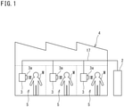
- FIG. 1 is a schematic configuration diagram of an air conditioner according to an embodiment of the present invention.
- An air conditioner 1 of the present embodiment is a spot-type air conditioner configured to individually blow out temperature-controlled air to a plurality of work areas 5 set in a large continuous space of, for example, a factory 4.
- the air conditioner 1 includes one or more outdoor units (heat source units) 2 and a plurality of indoor units (utilization units) 3.
- the outdoor unit 2 and the indoor units 3 are connected by a connection pipe 17.
- the outdoor unit 2 is installed outside the factory 4, and the indoor units 3 are each installed in the corresponding one of the plurality of work areas 5 in the factory 4.
- Each of the indoor units 3 includes a blow-out port 3a for blowing out air in a concentrated manner.
- the indoor units 3 are each configured to directly blow out air, through the blow-out port 3a, onto a worker M working in the work area 5 to provide the worker M with a comfortable working environment.
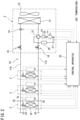
- FIG. 2 is a schematic diagram of a refrigerant circuit of the air conditioner 1.
- the plurality of indoor units 3 is connected in parallel to one outdoor unit 2 to form a refrigerant circuit 10 through which refrigerant flows.
- the air conditioner 1 also includes a control apparatus 30 that controls the entire operation.
- Each of the indoor units 3 includes an indoor expansion valve (decompressing device) 15, an indoor heat exchanger 16 and the like, which are connected by a refrigerant pipe.
- the indoor unit 3 further includes a fan 22 and the like.
- the indoor expansion valve 15 is for decompressing the refrigerant flowing through the refrigerant circuit 10 to adjust a flow rate of the refrigerant.
- the indoor heat exchanger 16 is, for example, a cross-fin type fin-and-tube heat exchanger.
- the fan 22 is disposed near the indoor heat exchanger 16, and is configured to generate an air flow passing through the indoor heat exchanger 16 to thereby exchange heat between the air and the refrigerant flowing through the indoor heat exchanger 16, and to blow out temperature-controlled air from the blow-out port 3a.
- the indoor unit 3 also includes various sensors.
- a liquid-side temperature sensor 24 is provided on a liquid side of the indoor heat exchanger 16. The liquid-side temperature sensor 24 detects a temperature of refrigerant in a liquid state or a gas-liquid two-phase state.
- a gas-side temperature sensor 25 is provided on a gas side of the indoor heat exchanger 16. The gas-side temperature sensor 25 detects a temperature of refrigerant in a gas state.
- a blow-out temperature sensor (cooling or heating temperature sensor) 26 is provided near the blow-out port 3a of the indoor unit 3. The blow-out temperature sensor 26 detects a temperature of air blown out from the blow-out port 3a.
- the outdoor unit 2 includes a compressor 11, a four-way switching valve (switching device) 12, an outdoor heat exchanger 13, an outdoor expansion valve 14, an accumulator 20, an oil separator 21 and the like, which are connected by refrigerant pipes.
- the outdoor unit 2 also includes a fan 23.
- the four-way switching valve 12 and the indoor heat exchanger 16 are connected by a gas-side connection pipe 17a.
- the outdoor expansion valve 14 and the indoor expansion valve 15 are connected by a liquid-side connection pipe 17b.
- the compressor 11 is a hermetic compressor in which a compression element (not illustrated) and a motor (not illustrated) for driving the compression element are housed in a casing. Electric power is supplied to the motor via an inverter device (not illustrated).
- the motor is configured to change an operating capacity of the compressor 11 by changing an output frequency of the inverter device, that is, the number of rotations of the motor.
- the four-way switching valve 12 is for switching a flowing direction of the refrigerant, and connects a discharge side of the compressor 11 and a gas side of the outdoor heat exchanger 13 and connects a suction side of the compressor 11 and the gas-side connection pipe 17a during a cooling operation as one of the air conditioning operations.
- the four-way switching valve 12 connects the discharge side of the compressor 11 and the gas-side connection pipe 17a and connects the suction side of the compressor 11 and the gas side of the outdoor heat exchanger 13.
- the outdoor heat exchanger 13 is, for example, a cross-fin type fin-and-tube heat exchanger.
- the outdoor expansion valve 14 is for decompressing the refrigerant flowing through the refrigerant circuit 10.
- the fan 23 is disposed near the outdoor heat exchanger 13, and generates an air flow passing through the outdoor heat exchanger 13 to thereby exchange heat between the air and the refrigerant flowing through the indoor heat exchanger 16.
- the accumulator 20 is a closed vessel connected between the four-way switching valve 12 and the suction side of the compressor 11.
- the accumulator 20 separates the liquid phase from the gas phase contained in the refrigerant, and only supplies the gas phase to the compressor 11.
- the oil separator 21 is used to separate refrigeration oil contained in the refrigerant discharged from the compressor 11 and return the refrigeration oil to the compressor 11.
- a gas-side shutoff valve 18 and a liquid-side shutoff valve 19 are provided at terminal portions of an internal refrigerant circuit of the outdoor unit 2.
- the gas-side shutoff valve 18 is disposed on the side of the four-way switching valve 12, and the liquid-side shutoff valve 19 is disposed on the side of the outdoor expansion valve 14.
- the gas-side connection pipe 17a is connected to the gas-side shutoff valve 18, and the liquid-side connection pipe 17b is connected to the liquid-side shutoff valve 19.
- the outdoor unit 2 also includes various sensors. For example, a suction pressure sensor 27 is provided on the suction side of the compressor 11. A discharge pressure sensor 28 is provided on the discharge side of the compressor 11.
- the control apparatus 30 includes, for example, an indoor control unit (not illustrated) provided in each indoor unit 3, and an outdoor control unit (not illustrated) provided in the outdoor unit 2.
- the control apparatus 30 includes a microcomputer, a memory, a communication interface and the like. Signals from the various sensors provided in the indoor units 3 and the outdoor unit 2 are input to the control apparatus 30.
- the control apparatus 30 controls the operations of, for example, the compressor 11, the valves 12, 14, and 15, and the fans 22 and 23.
- the control apparatus 30 can receive, through a remote controller or the like connected to each indoor unit 3, an input of a target value (set temperature) of a blow-out temperature (cooling temperature or heating temperature) at the indoor unit 3.
- FIG. 3 is a configuration diagram of functions of the control apparatus 30 of the air conditioner 1.
- the control apparatus 30 functionally includes a required capacity acquisition unit 31, a target refrigerant temperature setting unit 32, a target refrigerant state setting unit 33, a target refrigerant state changing unit 34, a compressor control unit 35, and an expansion valve control unit 36.
- the required capacity acquisition unit 31 is a functional unit that acquires the required capacity of each indoor unit 3.
- the target refrigerant temperature setting unit 32 is a functional unit that sets a target value of an evaporation temperature or a condensation temperature in the indoor heat exchanger 16 and the outdoor heat exchanger 13.
- the target refrigerant state setting unit 33 is a functional unit that sets a predetermined refrigerant state, which is, in the present embodiment, a target value of the degree of superheating or subcooling of the refrigerant.
- the target refrigerant state changing unit 34 is a functional unit that changes the target value of the degree of superheating or subcooling of the refrigerant based on a predetermined condition. The predetermined condition will be described together with actual operation control of the air conditioner.
- the compressor control unit 35 is a functional unit that controls the operation of the compressor 11.
- the compressor control unit 35 according to the present embodiment is configured to control the operation of the compressor 11 based on the target value of the evaporation temperature or the condensation temperature set by the target refrigerant temperature setting unit 32.
- the expansion valve control unit 36 is a functional unit that controls the operations of the indoor expansion valve 15 and the outdoor expansion valve 14. Particularly in the present embodiment, the expansion valve control unit 36 is configured to control the opening degree of the indoor expansion valve 15 based on the refrigerant state (the degree of superheating or subcooling in the indoor heat exchanger 16) set by the target refrigerant state setting unit 33 and the target refrigerant state changing unit 34.
- the four-way switching valve 12 is held in a state illustrated by the solid line in FIG. 2 .
- High-temperature, high-pressure gaseous refrigerant discharged from the compressor 11 flows through the oil separator 21 and the four-way switching valve 12 into the outdoor heat exchanger 13 serving as a condenser, exchanges heat with outdoor air through the operation of the fan 23, and is condensed and liquefied.
- the liquefied refrigerant passes through the fully opened outdoor expansion valve 14, and flows into each indoor unit 3 through the liquid-side connection pipe 17b.
- the refrigerant is decompressed to a predetermined low pressure by the indoor expansion valve 15, further exchanges heat with air in the work area 5 (see FIG.
- the indoor heat exchanger 16 serving as an evaporator, and evaporates.
- the air cooled by the evaporation of the refrigerant is blown out into the work area 5 by the fan 22 and blown onto the worker M.
- the refrigerant evaporated and vaporized in the indoor heat exchanger 16 returns to the outdoor unit 2 through the gas-side connection pipe 17a, and is sucked into the compressor 11 through the four-way switching valve 12 and the accumulator 20.
- the four-way switching valve 12 is held in a state illustrated by the broken line in FIG. 2 .
- the high-temperature, high-pressure gaseous refrigerant discharged from the compressor 11 flows through the oil separator 21 and the four-way switching valve 12 into the indoor heat exchanger 16 serving as a condenser of each indoor unit 3, exchanges heat with the air in the work area 5, and is condensed and liquefied.
- the air heated by the condensation of the refrigerant is blown out into the work area 5 by the fan 22 and blown onto the worker M.
- the refrigerant liquefied in the indoor heat exchanger 16 returns to the outdoor unit 2 from the fully opened indoor expansion valve 15 through the liquid-side connection pipe 17b.
- the refrigerant that has returned to the outdoor unit 2 is decompressed to a predetermined low pressure by the outdoor expansion valve 14, further exchanges heat with outdoor air by the outdoor heat exchanger 13, and evaporates.
- the refrigerant evaporated and vaporized in the outdoor heat exchanger 13 is sucked into the compressor 11 through the four-way switching valve 12 and the accumulator 20.
- the air conditioner 1 is controlled such that a blow-out temperature (cooling temperature) Tf of air blown out from each indoor unit 3 becomes a target value (set temperature) Tfm.
- the target value Tfm is input to the control apparatus 30 via, for example, a remote controller of each indoor unit 3.
- the number of rotations of the compressor 11 in the outdoor unit 2 is controlled by the compressor control unit 35 of the control apparatus 30 such that an evaporation temperature Te of the indoor heat exchanger 16 serving as an evaporator becomes a preset target value Tem.
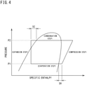
- the evaporation temperature Te is a temperature at which the refrigerant evaporates at an evaporation pressure P1 of FIG. 4 , and is a temperature of the refrigerant detected by the liquid-side temperature sensor 24.
- the compressor 11 is controlled such that the number of rotations thereof increases.
- the compressor 11 is controlled such that the number of rotations thereof decreases.
- the target evaporation temperature Tem is the same for all the indoor units 3.
- the opening degree of the indoor expansion valve 15 in the indoor unit 3 is controlled by the expansion valve control unit 36 of the control apparatus 30 such that a degree of superheating SH (see FIG. 4 ) of the refrigerant at the outlet of the indoor heat exchanger 16 becomes a preset target value SHm.
- a degree of superheating SH of the refrigerant is larger than the target value SHm (SH > SHm)
- the indoor expansion valve 15 is controlled such that the opening degree thereof is increased to expand a refrigerant flow path and the flow rate of the refrigerant flowing through the indoor heat exchanger 16 is increased.
- the indoor expansion valve 15 is controlled such that the opening degree thereof is decreased to narrow the refrigerant flow path and the flow rate of the refrigerant flowing through the indoor heat exchanger 16 is decreased.
- the degree of superheating SH of the refrigerant can be obtained based on a difference between a refrigerant temperature at the outlet of the indoor heat exchanger 16 detected by the gas-side temperature sensor 25 and a refrigerant temperature at the inlet of the indoor heat exchanger 16 detected by the liquid-side temperature sensor 24 (evaporation temperature Te).
- the above control of the compressor 11 and the indoor expansion valve 15 allows the blow-out temperature Tf of each indoor unit 3 to become the target value (set temperature) Tfm.
- the method of obtaining the degree of superheating SH of the refrigerant at the outlet of the indoor heat exchanger 16 is not limited to the method described above.
- the degree of superheating SH may be obtained in such a manner that the suction pressure of the compressor 11 detected by the suction pressure sensor 27 is converted into a saturation temperature value corresponding to the evaporation temperature Te, and the saturation temperature value is subtracted from the value detected by the gas-side temperature sensor 25.
- FIG. 5 is a flowchart of a procedure for setting the target evaporation temperature Tem and the target degree of superheating SHm.
- the target evaporation temperature Tem of the refrigerant in the indoor heat exchanger 16 is set by the target refrigerant temperature setting unit 32 of the control apparatus 30 in accordance with the required capacity of the indoor unit 3. Specifically, the target evaporation temperature Tem is set based on the largest required capacity among the required capacities of the plurality of indoor units 3.
- step S1 of FIG. 5 the required capacity of each indoor unit 3 is calculated by the required capacity acquisition unit 31 of the control apparatus 30 based on a differential temperature ⁇ Tf that is obtained by subtracting the target blow-out temperature Tfm preset by the indoor unit 3 from the actual blow-out temperature Tf detected by the blow-out temperature sensor 26 as in the following formula (1). Therefore, the larger the differential temperature ⁇ Tf, the larger the required capacity.
- ⁇ Tf Tf ⁇ Tfm
- the target evaporation temperature Tem is set by the target refrigerant temperature setting unit 32 of the control apparatus 30 to, for example, a temperature that is several to ten-odd degrees lower than the target blow-out temperature Tfm of the indoor unit 3 having the largest required capacity.
- the required capacity of each indoor unit 3 is constantly acquired during the operation, and the target evaporation temperature Tem is changed in accordance with the change of the required capacity. Determining the required capacity based on the differential temperature ⁇ Tf between the blow-out temperature Tf and the target blow-out temperature Tfm is an example.
- the suction temperature of the indoor unit 3, or the evaporation temperature or the condensation temperature of the refrigerant at the time of flowing through the indoor unit 3 may be used instead of the blow-out temperature Tf.
- the target degree of superheating SHm at the outlet of the indoor heat exchanger 16 in the indoor unit 3 is predetermined to be suitable for the target evaporation temperature Tem.
- These values SHm and Tem are stored, in association with each other, in a storage unit of the control apparatus 30. Therefore, after the control apparatus 30 sets the target evaporation temperature Tem in accordance with the largest required capacity, the control apparatus 30 causes the target refrigerant state setting unit 33 to read, from the storage unit, and set the target degree of superheating SHm suitable for the target evaporation temperature Tem in step S3 of FIG. 5 . Then, in each indoor unit 3, the opening degree of the indoor expansion valve 15 is controlled such that the degree of superheating SH at the outlet of the indoor heat exchanger 16 becomes the target degree of superheating SHm.
- the target degree of superheating SHm can be appropriately changed from a value set in accordance with the target evaporation temperature Tem to an optimum value in accordance with the change of the operating condition.
- the target degree of superheating SHm may be changed in accordance with a change of an average value of the target blow-out temperatures Tfm in the plurality of indoor units 3, a change of an average value of the blow-out temperatures Tf in the plurality of indoor units 3, or a change of a refrigerant pressure (low pressure value) in the indoor heat exchanger 16 or a refrigerant pressure (high pressure value) in the outdoor heat exchanger 13.
- the control apparatus 30 of the present embodiment is configured to perform control for individually changing the target degree of superheating SHm in each indoor unit 3 when the blow-out temperature Tf of the corresponding indoor unit 3 satisfies a predetermined relationship with the target blow-out temperature Tfm in step S4 of FIG. 5 .
- control is performed such that the target degree of superheating SHm is changed to reduce the cooling capacity when the blow-out temperature Tf of the indoor unit 3 becomes lower than the target blow-out temperature Tfm by a predetermined value ⁇ t or more.
- the indoor expansion valve 15 is controlled such that the opening degree thereof decreases to decrease the flow rate of the refrigerant, and the cooling capacity in the indoor heat exchanger 16 is lowered.
- the blow-out temperature Tf rises gradually, and air can be blown onto the worker M at an appropriate temperature.
- the target degree of superheating SHm is changed after the blow-out temperature Tf has become lower than the target blow-out temperature Tfm by the predetermined value ⁇ t or more, for the following reason. That is, this is for the purpose of giving desired comfort to the worker M by making the blow-out temperature Tf reach the target blow-out temperature Tfm without fail and blowing the air onto the worker M. Reducing the cooling capacity when the formula (2) is satisfied makes it possible to suppress excessive cooling.
- the basic operation control is substantially the same as that for the cooling operation.
- the air conditioner 1 is controlled such that a blow-out temperature (heating temperature) Tf of air blown out from each indoor unit 3 becomes a target value (set temperature) Tfm.
- the target value Tfm is input to the control apparatus 30 via, for example, the remote controller of each indoor unit 3.
- the number of rotations of the compressor 11 in the outdoor unit 2 is controlled by the compressor control unit 35 of the control apparatus 30 such that a condensation temperature Tc of the indoor heat exchanger 16 serving as a condenser in each indoor unit 3 becomes a preset target value Tcm.
- the condensation temperature Tc is a temperature at which the refrigerant condenses at a condensation pressure P2 of FIG. 4 .
- the compressor 11 is controlled such that the number of rotations thereof increases.
- the condensation temperature Tc is higher than the target condensation temperature Tcm (Tc > Tcm)
- the compressor 11 is controlled such that the number of rotations thereof decreases.
- the target condensation temperature Tcm is the same for all the indoor units 3.
- the opening degree of the indoor expansion valve 15 in the indoor unit 3 is controlled by the expansion valve control unit 36 of the control apparatus 30 such that a degree of subcooling SC (see FIG. 4 ) of the refrigerant at the outlet of the indoor heat exchanger 16 becomes a preset target value SCm.
- a degree of subcooling SC see FIG. 4
- SCm target value
- the indoor expansion valve 15 is controlled such that the opening degree thereof is increased to increase the flow rate of the refrigerant flowing through the indoor heat exchanger 16.
- the indoor expansion valve 15 is controlled such that the opening degree thereof is decreased to decrease the flow rate of the refrigerant flowing through the indoor heat exchanger 16.
- the degree of subcooling SC of the refrigerant can be calculated in such a manner that the discharge pressure of the compressor 11 detected by the discharge pressure sensor 28 is converted into a saturation temperature value corresponding to the condensation temperature Tc, and the refrigerant temperature detected by the liquid-side temperature sensor 24 is subtracted from the saturation temperature value of the refrigerant.
- the above control of the compressor 11 and the indoor expansion valve 15 allows the blow-out temperature Tf of each indoor unit 3 to become the target value Tfm.
- the target condensation temperature Tcm of the refrigerant in the indoor heat exchanger 16 is set by the target refrigerant temperature acquisition unit of the control apparatus 30 in accordance with the required capacity of the indoor unit 3. Specifically, the target condensation temperature Tcm is set based on the largest required capacity among the required capacities of the plurality of indoor units 3.
- the required capacity of each indoor unit 3 is calculated by the required capacity acquisition unit of the control apparatus 30 based on a differential temperature ⁇ Tf that is obtained by subtracting the target blow-out temperature Tfm preset by the indoor unit 3 from the actual blow-out temperature Tf detected by the blow-out temperature sensor 26 of the indoor unit 3. Therefore, the larger the differential temperature ⁇ Tf, the larger the required capacity.
- the target condensation temperature Tcm is set to, for example, a temperature that is several to ten-odd degrees higher than the target blow-out temperature Tfm of the indoor unit 3 having the largest required capacity.
- the required capacity of each indoor unit 3 is constantly acquired during the operation, and the target condensation temperature Tcm is changed in accordance with the change of the required capacity.
- the target degree of subcooling SCm at the outlet of the indoor heat exchanger 16 in the indoor unit 3 is predetermined to be suitable for the target condensation temperature Tcm.
- These values SCm and Tcm are stored, in association with each other, in the storage unit or the like of the control apparatus 30. Therefore, after the control apparatus 30 sets the target condensation temperature Tcm by the target refrigerant temperature setting unit 32 in accordance with the largest required capacity, the control apparatus 30 causes the target refrigerant state setting unit 33 to read, from the storage unit, and set the target degree of subcooling SCm suitable for the target condensation temperature. Then, in each indoor unit 3, the opening degree of the indoor expansion valve 15 is controlled such that the degree of subcooling SC at the outlet of the indoor heat exchanger 16 becomes the target degree of subcooling SCm.
- each indoor unit 3 is configured to perform control for individually changing the target degree of superheating SHm in the indoor unit 3 when the blow-out temperature Tf of the indoor unit 3 satisfies a predetermined relationship with the target blow-out temperature Tfm.
- the liquid refrigerant may be accumulated in a specific indoor heat exchanger 16, and the amount of refrigerant flowing through the entire refrigerant circuit of the air conditioner 1 may be insufficient.
- the heating capacity is maintained without changing the target degree of subcooling SCm, even if the blow-out temperature Tf rises significantly above the target blow-out temperature Tfm during the heating operation. This enhances the reliability of the air conditioner 1.
- the spot-type utilization unit in the above embodiment may be installed outdoors.
- the air conditioner according to the present invention is not limited to one including a spot-type utilization unit, but may alternatively include a utilization unit that adjusts a temperature of an entire space such as the interior of a room.
Landscapes
- Engineering & Computer Science (AREA)
- Mechanical Engineering (AREA)
- General Engineering & Computer Science (AREA)
- Combustion & Propulsion (AREA)
- Chemical & Material Sciences (AREA)
- Signal Processing (AREA)
- Physics & Mathematics (AREA)
- Mathematical Physics (AREA)
- Fuzzy Systems (AREA)
- Thermal Sciences (AREA)
- General Physics & Mathematics (AREA)
- Automation & Control Theory (AREA)
- Air Conditioning Control Device (AREA)
Claims (4)
- Climatiseur (1) comprenant:une unité source de chaleur (2) incluant un compresseur (11) et un échangeur de chaleur côté source de chaleur (13) ;une pluralité d'unités d'utilisation (3) incluant chacune un dispositif de décompression (15) et un échangeur de chaleur côté utilisation (16),la pluralité d'unités d'utilisation (3) étant reliées en parallèle à l'unité source de chaleur (2) pour former un circuit de réfrigérant (10), le climatiseur (1) réalisant une opération de refroidissement en utilisant l'échangeur de chaleur côté source de chaleur (13) comme condenseur et l'échangeur de chaleur côté utilisation (16) comme évaporateur ; etun dispositif de passage (12) faisant passer l'opération de refroidissement à une opération de chauffage dans laquelle l'échangeur de chaleur côté source de chaleur (13) est utilisé comme évaporateur et l'échangeur de chaleur côté utilisation (16) est utilisé comme condenseur,le climatiseur (1) comprenant en outre :un capteur de détection (26) détectant un état d'air lié à une capacité exigée de chacune des unités d'utilisation (3) ; etun appareil de commande (30) configuré pour :acquérir la capacité exigée de chacune des unités d'utilisation (3) sur la base d'un résultat de détection du capteur de détection (26),durant l'opération de refroidissement, définir une valeur cible (Tem) d'une température d'évaporation (Te) dans l'échangeur de chaleur côté utilisation (16) ajustée par le compresseur (11) conformément à la capacité exigée la plus élevée,durant l'opération de chauffage, définir une valeur cible (Tcm) d'une température de condensation (Tc) dans l'échangeur de chaleur côté utilisation (16) ajustée par le compresseur (11) conformément à la capacité exigée la plus élevée ;caractérisé en ce que l'appareil de commande (30) est en outre configuré pour :durant l'opération de refroidissement, définir une valeur cible (SHm) d'un état de réfrigérant (SH) prédéterminé ajusté par le dispositif de décompression (15) conformément à la capacité exigée la plus élevée,lorsque durant l'opération de refroidissement une température de refroidissement (Tf) devient inférieure à une température de refroidissement cible (Tfm) d'une valeur prédéterminée (Δt) ou plus dans une des unités d'utilisation (3) autre que l'unité d'utilisation (3) présentant la capacité exigée la plus élevée, changer la valeur cible (SHm) de l'état de réfrigérant (SH) de telle sorte qu'une capacité de refroidissement de l'autre unité d'utilisation (3) soit réduite,durant l'opération de chauffage, définir une valeur cible (SCm) d'un état de réfrigérant (SC) prédéterminé ajusté par le dispositif de décompression (15) conformément à la capacité exigée la plus élevée, etmême lorsque durant l'opération de chauffage une température de chauffage (Tf) dépasse une température de chauffage cible (Tfm) dans une des unités d'utilisation (3) autre que l'unité d'utilisation (3) présentant la capacité exigée la plus élevée, maintenir la valeur cible (SCm) de l'état de réfrigérant (SC).
- Climatiseur selon la revendication 1, dans lequell'état de réfrigérant (SH) est un degré de surchauffe, etl'appareil de commande (30) est configuré pour, lorsque la température de refroidissement (Tf) devient inférieure à la température de refroidissement cible (Tfm) de la valeur prédéterminée (Δt) ou plus dans l'autre unité d'utilisation (3), définir la valeur cible (SHm) du degré de surchauffe (SH) plus élevée qu'avant que la température de refroidissement (Tf) ne soit réduite.
- Climatiseur selon la revendication 1 ou 2, dans lequel
l'appareil de commande (30) est configuré pour, lorsque la température de refroidissement (Tf) devient inférieure à la température de refroidissement cible (Tfm) de la valeur prédéterminée (Δt) ou plus dans l'autre unité d'utilisation (3), commander le dispositif de décompression (15) de telle sorte qu'un trajet d'écoulement de réfrigérant dans le dispositif de décompression (15) devienne plus étroit qu'avant que la température de refroidissement (Tf) ne soit réduite. - Climatiseur selon l'une quelconque des revendications 1 à 3, dans lequel
chacune des unités d'utilisation (3) est d'un type ponctuel qui souffle de l'air à température commandée directement sur une cible devant être refroidie.
Applications Claiming Priority (2)
| Application Number | Priority Date | Filing Date | Title |
|---|---|---|---|
| JP2017033244A JP6493432B2 (ja) | 2017-02-24 | 2017-02-24 | 空気調和装置 |
| PCT/JP2018/002187 WO2018155056A1 (fr) | 2017-02-24 | 2018-01-25 | Climatiseur |
Publications (3)
| Publication Number | Publication Date |
|---|---|
| EP3587948A1 EP3587948A1 (fr) | 2020-01-01 |
| EP3587948A4 EP3587948A4 (fr) | 2021-02-24 |
| EP3587948B1 true EP3587948B1 (fr) | 2022-02-23 |
Family
ID=63253818
Family Applications (1)
| Application Number | Title | Priority Date | Filing Date |
|---|---|---|---|
| EP18757406.6A Active EP3587948B1 (fr) | 2017-02-24 | 2018-01-25 | Climatiseur |
Country Status (5)
| Country | Link |
|---|---|
| US (1) | US10955160B2 (fr) |
| EP (1) | EP3587948B1 (fr) |
| JP (1) | JP6493432B2 (fr) |
| CN (1) | CN110337570B (fr) |
| WO (1) | WO2018155056A1 (fr) |
Families Citing this family (9)
| Publication number | Priority date | Publication date | Assignee | Title |
|---|---|---|---|---|
| US11060779B2 (en) * | 2018-02-07 | 2021-07-13 | Mitsubishi Electric Corporation | Air-conditioning system and air-conditioning control method |
| GB201802559D0 (en) * | 2018-02-16 | 2018-04-04 | Jaguar Land Rover Ltd | Apparatus and method for lubricant management in an electric vehicle |
| WO2020157851A1 (fr) | 2019-01-30 | 2020-08-06 | 三菱電機株式会社 | Dispositif de climatisation |
| JP6791315B1 (ja) * | 2019-07-18 | 2020-11-25 | ダイキン工業株式会社 | 冷凍装置 |
| JP7372122B2 (ja) * | 2019-11-20 | 2023-10-31 | Ckd株式会社 | 冷却システム |
| CN111023402B (zh) * | 2019-12-31 | 2021-08-06 | 宁波奥克斯电气股份有限公司 | 一种空调系统的自适应调节方法及空调器 |
| WO2023084608A1 (fr) | 2021-11-09 | 2023-05-19 | 三菱電機株式会社 | Dispositif de commande et procédé de commande |
| WO2023139700A1 (fr) | 2022-01-19 | 2023-07-27 | 三菱電機株式会社 | Dispositif de réfrigération et de climatisation |
| CN115597331B (zh) * | 2022-10-24 | 2024-07-23 | 广东芬尼克兹环保科技有限公司 | 高温烘干机及其控制方法 |
Family Cites Families (15)
| Publication number | Priority date | Publication date | Assignee | Title |
|---|---|---|---|---|
| JP3643162B2 (ja) * | 1995-12-27 | 2005-04-27 | 東プレ株式会社 | 空気調和装置 |
| US7426453B2 (en) * | 2005-01-14 | 2008-09-16 | Hewlett-Packard Development Company, L.P. | Workload placement based upon CRAC unit capacity utilizations |
| JP2008175507A (ja) * | 2007-01-22 | 2008-07-31 | Denso Facilities Corp | 工場内スポット空調設備 |
| JP4947221B2 (ja) * | 2010-05-11 | 2012-06-06 | ダイキン工業株式会社 | 空気調和装置の運転制御装置及びそれを備えた空気調和装置 |
| JP6275372B2 (ja) * | 2011-09-05 | 2018-02-07 | 株式会社デンソー | 冷凍サイクル装置 |
| WO2013069043A1 (fr) * | 2011-11-07 | 2013-05-16 | 三菱電機株式会社 | Appareil de climatisation |
| US9746216B2 (en) * | 2012-06-29 | 2017-08-29 | Mitsubishi Electric Corporation | Heat pump device, heat pump system, air conditioner, and freezer |
| JP6051849B2 (ja) * | 2012-12-26 | 2016-12-27 | ダイキン工業株式会社 | 空気調和システム |
| WO2014118953A1 (fr) * | 2013-01-31 | 2014-08-07 | 三菱電機株式会社 | Dispositif à cycle frigorifique et procédé de contrôle du dispositif à cycle frigorifique |
| EP3001121B1 (fr) * | 2013-05-23 | 2020-10-14 | Mitsubishi Electric Corporation | Dispositif de pompe à chaleur |
| JP5780280B2 (ja) * | 2013-09-30 | 2015-09-16 | ダイキン工業株式会社 | 空調システム及びその制御方法 |
| JP5979112B2 (ja) * | 2013-09-30 | 2016-08-24 | ダイキン工業株式会社 | 冷凍装置 |
| JP6222019B2 (ja) * | 2014-09-05 | 2017-11-01 | 株式会社デンソー | 二段昇圧式冷凍サイクル装置 |
| JP6028816B2 (ja) * | 2015-01-30 | 2016-11-24 | ダイキン工業株式会社 | 空気調和装置 |
| JP6609417B2 (ja) * | 2015-04-03 | 2019-11-20 | 日立ジョンソンコントロールズ空調株式会社 | 空気調和機 |
-
2017
- 2017-02-24 JP JP2017033244A patent/JP6493432B2/ja active Active
-
2018
- 2018-01-25 CN CN201880013741.XA patent/CN110337570B/zh active Active
- 2018-01-25 US US16/476,693 patent/US10955160B2/en active Active
- 2018-01-25 WO PCT/JP2018/002187 patent/WO2018155056A1/fr unknown
- 2018-01-25 EP EP18757406.6A patent/EP3587948B1/fr active Active
Also Published As
| Publication number | Publication date |
|---|---|
| CN110337570A (zh) | 2019-10-15 |
| US20200378642A1 (en) | 2020-12-03 |
| US10955160B2 (en) | 2021-03-23 |
| EP3587948A4 (fr) | 2021-02-24 |
| EP3587948A1 (fr) | 2020-01-01 |
| CN110337570B (zh) | 2020-10-30 |
| WO2018155056A1 (fr) | 2018-08-30 |
| JP6493432B2 (ja) | 2019-04-03 |
| JP2018138841A (ja) | 2018-09-06 |
Similar Documents
| Publication | Publication Date | Title |
|---|---|---|
| EP3587948B1 (fr) | Climatiseur | |
| EP2940395B1 (fr) | Climatiseur | |
| EP3683524B1 (fr) | Dispositif frigorifique | |
| EP2270405B1 (fr) | Dispositif de refrigeration | |
| US9683768B2 (en) | Air-conditioning apparatus | |
| JP4740984B2 (ja) | 冷凍空調装置 | |
| US9958171B2 (en) | Air-conditioning apparatus | |
| US8522568B2 (en) | Refrigeration system | |
| US8020395B2 (en) | Air conditioning apparatus | |
| EP3657090B1 (fr) | Système de climatisation | |
| EP2196746B1 (fr) | Appareil de réfrigération | |
| EP2375188A1 (fr) | Climatiseur | |
| JP2002054836A (ja) | 室内マルチ空気調和機 | |
| EP3690356A1 (fr) | Dispositif à cycle frigorifique | |
| JP6067178B2 (ja) | 熱源側ユニット及び空気調和装置 | |
| CN109312961B (zh) | 制冷装置的热源机组 | |
| JP5506433B2 (ja) | マルチ型空気調和機 | |
| JP2006234239A (ja) | 空気調和装置のアキュームレータ内液冷媒検出方法、レシーバ内液冷媒検出方法、冷媒量調整方法、及び空気調和装置 | |
| JP6537629B2 (ja) | 空気調和装置 | |
| JP3945523B2 (ja) | 冷凍装置 | |
| WO2020208805A1 (fr) | Dispositif de climatisation | |
| KR20090107310A (ko) | 멀티형 공기조화기 및 그 난방운전 협조제어 방법 | |
| EP4310416A1 (fr) | Système de climatisation multiple hybride |
Legal Events
| Date | Code | Title | Description |
|---|---|---|---|
| STAA | Information on the status of an ep patent application or granted ep patent |
Free format text: STATUS: THE INTERNATIONAL PUBLICATION HAS BEEN MADE |
|
| PUAI | Public reference made under article 153(3) epc to a published international application that has entered the european phase |
Free format text: ORIGINAL CODE: 0009012 |
|
| STAA | Information on the status of an ep patent application or granted ep patent |
Free format text: STATUS: REQUEST FOR EXAMINATION WAS MADE |
|
| 17P | Request for examination filed |
Effective date: 20190712 |
|
| AK | Designated contracting states |
Kind code of ref document: A1 Designated state(s): AL AT BE BG CH CY CZ DE DK EE ES FI FR GB GR HR HU IE IS IT LI LT LU LV MC MK MT NL NO PL PT RO RS SE SI SK SM TR |
|
| AX | Request for extension of the european patent |
Extension state: BA ME |
|
| DAV | Request for validation of the european patent (deleted) | ||
| DAX | Request for extension of the european patent (deleted) | ||
| A4 | Supplementary search report drawn up and despatched |
Effective date: 20210122 |
|
| RIC1 | Information provided on ipc code assigned before grant |
Ipc: F25B 6/02 20060101ALI20210118BHEP Ipc: F25B 5/02 20060101ALI20210118BHEP Ipc: F24F 3/00 20060101ALI20210118BHEP Ipc: F25B 30/02 20060101ALI20210118BHEP Ipc: F24F 11/64 20180101ALI20210118BHEP Ipc: F24F 110/10 20180101ALI20210118BHEP Ipc: F24F 11/67 20180101ALI20210118BHEP Ipc: F25B 13/00 20060101ALI20210118BHEP Ipc: F25B 49/02 20060101ALI20210118BHEP Ipc: F24F 11/86 20180101ALI20210118BHEP Ipc: F24F 3/06 20060101ALI20210118BHEP Ipc: F25B 1/00 20060101ALI20210118BHEP Ipc: F24F 11/84 20180101ALI20210118BHEP Ipc: F24F 11/49 20180101ALI20210118BHEP Ipc: F24F 11/46 20180101AFI20210118BHEP |
|
| GRAP | Despatch of communication of intention to grant a patent |
Free format text: ORIGINAL CODE: EPIDOSNIGR1 |
|
| STAA | Information on the status of an ep patent application or granted ep patent |
Free format text: STATUS: GRANT OF PATENT IS INTENDED |
|
| INTG | Intention to grant announced |
Effective date: 20211105 |
|
| GRAS | Grant fee paid |
Free format text: ORIGINAL CODE: EPIDOSNIGR3 |
|
| GRAA | (expected) grant |
Free format text: ORIGINAL CODE: 0009210 |
|
| STAA | Information on the status of an ep patent application or granted ep patent |
Free format text: STATUS: THE PATENT HAS BEEN GRANTED |
|
| AK | Designated contracting states |
Kind code of ref document: B1 Designated state(s): AL AT BE BG CH CY CZ DE DK EE ES FI FR GB GR HR HU IE IS IT LI LT LU LV MC MK MT NL NO PL PT RO RS SE SI SK SM TR |
|
| REG | Reference to a national code |
Ref country code: GB Ref legal event code: FG4D |
|
| REG | Reference to a national code |
Ref country code: CH Ref legal event code: EP |
|
| REG | Reference to a national code |
Ref country code: DE Ref legal event code: R096 Ref document number: 602018031277 Country of ref document: DE |
|
| REG | Reference to a national code |
Ref country code: AT Ref legal event code: REF Ref document number: 1470764 Country of ref document: AT Kind code of ref document: T Effective date: 20220315 |
|
| REG | Reference to a national code |
Ref country code: IE Ref legal event code: FG4D |
|
| REG | Reference to a national code |
Ref country code: LT Ref legal event code: MG9D |
|
| REG | Reference to a national code |
Ref country code: NL Ref legal event code: MP Effective date: 20220223 |
|
| REG | Reference to a national code |
Ref country code: AT Ref legal event code: MK05 Ref document number: 1470764 Country of ref document: AT Kind code of ref document: T Effective date: 20220223 |
|
| PG25 | Lapsed in a contracting state [announced via postgrant information from national office to epo] |
Ref country code: SE Free format text: LAPSE BECAUSE OF FAILURE TO SUBMIT A TRANSLATION OF THE DESCRIPTION OR TO PAY THE FEE WITHIN THE PRESCRIBED TIME-LIMIT Effective date: 20220223 Ref country code: RS Free format text: LAPSE BECAUSE OF FAILURE TO SUBMIT A TRANSLATION OF THE DESCRIPTION OR TO PAY THE FEE WITHIN THE PRESCRIBED TIME-LIMIT Effective date: 20220223 Ref country code: PT Free format text: LAPSE BECAUSE OF FAILURE TO SUBMIT A TRANSLATION OF THE DESCRIPTION OR TO PAY THE FEE WITHIN THE PRESCRIBED TIME-LIMIT Effective date: 20220623 Ref country code: NO Free format text: LAPSE BECAUSE OF FAILURE TO SUBMIT A TRANSLATION OF THE DESCRIPTION OR TO PAY THE FEE WITHIN THE PRESCRIBED TIME-LIMIT Effective date: 20220523 Ref country code: NL Free format text: LAPSE BECAUSE OF FAILURE TO SUBMIT A TRANSLATION OF THE DESCRIPTION OR TO PAY THE FEE WITHIN THE PRESCRIBED TIME-LIMIT Effective date: 20220223 Ref country code: LT Free format text: LAPSE BECAUSE OF FAILURE TO SUBMIT A TRANSLATION OF THE DESCRIPTION OR TO PAY THE FEE WITHIN THE PRESCRIBED TIME-LIMIT Effective date: 20220223 Ref country code: HR Free format text: LAPSE BECAUSE OF FAILURE TO SUBMIT A TRANSLATION OF THE DESCRIPTION OR TO PAY THE FEE WITHIN THE PRESCRIBED TIME-LIMIT Effective date: 20220223 Ref country code: ES Free format text: LAPSE BECAUSE OF FAILURE TO SUBMIT A TRANSLATION OF THE DESCRIPTION OR TO PAY THE FEE WITHIN THE PRESCRIBED TIME-LIMIT Effective date: 20220223 Ref country code: BG Free format text: LAPSE BECAUSE OF FAILURE TO SUBMIT A TRANSLATION OF THE DESCRIPTION OR TO PAY THE FEE WITHIN THE PRESCRIBED TIME-LIMIT Effective date: 20220523 |
|
| PG25 | Lapsed in a contracting state [announced via postgrant information from national office to epo] |
Ref country code: PL Free format text: LAPSE BECAUSE OF FAILURE TO SUBMIT A TRANSLATION OF THE DESCRIPTION OR TO PAY THE FEE WITHIN THE PRESCRIBED TIME-LIMIT Effective date: 20220223 Ref country code: LV Free format text: LAPSE BECAUSE OF FAILURE TO SUBMIT A TRANSLATION OF THE DESCRIPTION OR TO PAY THE FEE WITHIN THE PRESCRIBED TIME-LIMIT Effective date: 20220223 Ref country code: GR Free format text: LAPSE BECAUSE OF FAILURE TO SUBMIT A TRANSLATION OF THE DESCRIPTION OR TO PAY THE FEE WITHIN THE PRESCRIBED TIME-LIMIT Effective date: 20220524 Ref country code: FI Free format text: LAPSE BECAUSE OF FAILURE TO SUBMIT A TRANSLATION OF THE DESCRIPTION OR TO PAY THE FEE WITHIN THE PRESCRIBED TIME-LIMIT Effective date: 20220223 Ref country code: AT Free format text: LAPSE BECAUSE OF FAILURE TO SUBMIT A TRANSLATION OF THE DESCRIPTION OR TO PAY THE FEE WITHIN THE PRESCRIBED TIME-LIMIT Effective date: 20220223 |
|
| PG25 | Lapsed in a contracting state [announced via postgrant information from national office to epo] |
Ref country code: IS Free format text: LAPSE BECAUSE OF FAILURE TO SUBMIT A TRANSLATION OF THE DESCRIPTION OR TO PAY THE FEE WITHIN THE PRESCRIBED TIME-LIMIT Effective date: 20220623 |
|
| PG25 | Lapsed in a contracting state [announced via postgrant information from national office to epo] |
Ref country code: SM Free format text: LAPSE BECAUSE OF FAILURE TO SUBMIT A TRANSLATION OF THE DESCRIPTION OR TO PAY THE FEE WITHIN THE PRESCRIBED TIME-LIMIT Effective date: 20220223 Ref country code: SK Free format text: LAPSE BECAUSE OF FAILURE TO SUBMIT A TRANSLATION OF THE DESCRIPTION OR TO PAY THE FEE WITHIN THE PRESCRIBED TIME-LIMIT Effective date: 20220223 Ref country code: RO Free format text: LAPSE BECAUSE OF FAILURE TO SUBMIT A TRANSLATION OF THE DESCRIPTION OR TO PAY THE FEE WITHIN THE PRESCRIBED TIME-LIMIT Effective date: 20220223 Ref country code: EE Free format text: LAPSE BECAUSE OF FAILURE TO SUBMIT A TRANSLATION OF THE DESCRIPTION OR TO PAY THE FEE WITHIN THE PRESCRIBED TIME-LIMIT Effective date: 20220223 Ref country code: DK Free format text: LAPSE BECAUSE OF FAILURE TO SUBMIT A TRANSLATION OF THE DESCRIPTION OR TO PAY THE FEE WITHIN THE PRESCRIBED TIME-LIMIT Effective date: 20220223 Ref country code: CZ Free format text: LAPSE BECAUSE OF FAILURE TO SUBMIT A TRANSLATION OF THE DESCRIPTION OR TO PAY THE FEE WITHIN THE PRESCRIBED TIME-LIMIT Effective date: 20220223 |
|
| REG | Reference to a national code |
Ref country code: DE Ref legal event code: R097 Ref document number: 602018031277 Country of ref document: DE |
|
| PG25 | Lapsed in a contracting state [announced via postgrant information from national office to epo] |
Ref country code: AL Free format text: LAPSE BECAUSE OF FAILURE TO SUBMIT A TRANSLATION OF THE DESCRIPTION OR TO PAY THE FEE WITHIN THE PRESCRIBED TIME-LIMIT Effective date: 20220223 |
|
| PLBE | No opposition filed within time limit |
Free format text: ORIGINAL CODE: 0009261 |
|
| STAA | Information on the status of an ep patent application or granted ep patent |
Free format text: STATUS: NO OPPOSITION FILED WITHIN TIME LIMIT |
|
| 26N | No opposition filed |
Effective date: 20221124 |
|
| PG25 | Lapsed in a contracting state [announced via postgrant information from national office to epo] |
Ref country code: SI Free format text: LAPSE BECAUSE OF FAILURE TO SUBMIT A TRANSLATION OF THE DESCRIPTION OR TO PAY THE FEE WITHIN THE PRESCRIBED TIME-LIMIT Effective date: 20220223 |
|
| P01 | Opt-out of the competence of the unified patent court (upc) registered |
Effective date: 20230525 |
|
| PG25 | Lapsed in a contracting state [announced via postgrant information from national office to epo] |
Ref country code: IT Free format text: LAPSE BECAUSE OF FAILURE TO SUBMIT A TRANSLATION OF THE DESCRIPTION OR TO PAY THE FEE WITHIN THE PRESCRIBED TIME-LIMIT Effective date: 20220223 |
|
| REG | Reference to a national code |
Ref country code: CH Ref legal event code: PL |
|
| PG25 | Lapsed in a contracting state [announced via postgrant information from national office to epo] |
Ref country code: LU Free format text: LAPSE BECAUSE OF NON-PAYMENT OF DUE FEES Effective date: 20230125 |
|
| REG | Reference to a national code |
Ref country code: BE Ref legal event code: MM Effective date: 20230131 |
|
| PG25 | Lapsed in a contracting state [announced via postgrant information from national office to epo] |
Ref country code: LI Free format text: LAPSE BECAUSE OF NON-PAYMENT OF DUE FEES Effective date: 20230131 Ref country code: CH Free format text: LAPSE BECAUSE OF NON-PAYMENT OF DUE FEES Effective date: 20230131 |
|
| PG25 | Lapsed in a contracting state [announced via postgrant information from national office to epo] |
Ref country code: BE Free format text: LAPSE BECAUSE OF NON-PAYMENT OF DUE FEES Effective date: 20230131 |
|
| PGFP | Annual fee paid to national office [announced via postgrant information from national office to epo] |
Ref country code: GB Payment date: 20231207 Year of fee payment: 7 |
|
| PG25 | Lapsed in a contracting state [announced via postgrant information from national office to epo] |
Ref country code: IE Free format text: LAPSE BECAUSE OF NON-PAYMENT OF DUE FEES Effective date: 20230125 |
|
| PGFP | Annual fee paid to national office [announced via postgrant information from national office to epo] |
Ref country code: FR Payment date: 20231212 Year of fee payment: 7 |
|
| PGFP | Annual fee paid to national office [announced via postgrant information from national office to epo] |
Ref country code: DE Payment date: 20231128 Year of fee payment: 7 |
|
| PG25 | Lapsed in a contracting state [announced via postgrant information from national office to epo] |
Ref country code: MC Free format text: LAPSE BECAUSE OF FAILURE TO SUBMIT A TRANSLATION OF THE DESCRIPTION OR TO PAY THE FEE WITHIN THE PRESCRIBED TIME-LIMIT Effective date: 20220223 |
|
| PG25 | Lapsed in a contracting state [announced via postgrant information from national office to epo] |
Ref country code: MC Free format text: LAPSE BECAUSE OF FAILURE TO SUBMIT A TRANSLATION OF THE DESCRIPTION OR TO PAY THE FEE WITHIN THE PRESCRIBED TIME-LIMIT Effective date: 20220223 |