EP3586983B1 - Sieve machine and method for sieving powder-form material - Google Patents
Sieve machine and method for sieving powder-form material Download PDFInfo
- Publication number
- EP3586983B1 EP3586983B1 EP19177875.2A EP19177875A EP3586983B1 EP 3586983 B1 EP3586983 B1 EP 3586983B1 EP 19177875 A EP19177875 A EP 19177875A EP 3586983 B1 EP3586983 B1 EP 3586983B1
- Authority
- EP
- European Patent Office
- Prior art keywords
- sieve
- carrier
- outlet
- machine according
- form material
- Prior art date
- Legal status (The legal status is an assumption and is not a legal conclusion. Google has not performed a legal analysis and makes no representation as to the accuracy of the status listed.)
- Active
Links
- 239000000463 material Substances 0.000 title claims description 15
- 238000000034 method Methods 0.000 title claims description 7
- 238000007873 sieving Methods 0.000 title claims description 3
- 239000004020 conductor Substances 0.000 claims description 9
- 238000004140 cleaning Methods 0.000 claims description 6
- 229910052751 metal Inorganic materials 0.000 claims description 4
- 239000002184 metal Substances 0.000 claims description 4
- 238000012216 screening Methods 0.000 description 23
- 239000012254 powdered material Substances 0.000 description 11
- 239000011261 inert gas Substances 0.000 description 2
- 238000004519 manufacturing process Methods 0.000 description 2
- 239000002245 particle Substances 0.000 description 2
- 239000000843 powder Substances 0.000 description 2
- 238000010146 3D printing Methods 0.000 description 1
- 229910000831 Steel Inorganic materials 0.000 description 1
- 239000000654 additive Substances 0.000 description 1
- 230000000996 additive effect Effects 0.000 description 1
- 238000004026 adhesive bonding Methods 0.000 description 1
- XAGFODPZIPBFFR-UHFFFAOYSA-N aluminium Chemical compound [Al] XAGFODPZIPBFFR-UHFFFAOYSA-N 0.000 description 1
- 239000004744 fabric Substances 0.000 description 1
- 239000007789 gas Substances 0.000 description 1
- 239000010959 steel Substances 0.000 description 1
- 230000004936 stimulating effect Effects 0.000 description 1
- 238000002604 ultrasonography Methods 0.000 description 1
Images

Classifications
-
- B—PERFORMING OPERATIONS; TRANSPORTING
- B07—SEPARATING SOLIDS FROM SOLIDS; SORTING
- B07B—SEPARATING SOLIDS FROM SOLIDS BY SIEVING, SCREENING, SIFTING OR BY USING GAS CURRENTS; SEPARATING BY OTHER DRY METHODS APPLICABLE TO BULK MATERIAL, e.g. LOOSE ARTICLES FIT TO BE HANDLED LIKE BULK MATERIAL
- B07B1/00—Sieving, screening, sifting, or sorting solid materials using networks, gratings, grids, or the like
- B07B1/46—Constructional details of screens in general; Cleaning or heating of screens
- B07B1/50—Cleaning
-
- B—PERFORMING OPERATIONS; TRANSPORTING
- B07—SEPARATING SOLIDS FROM SOLIDS; SORTING
- B07B—SEPARATING SOLIDS FROM SOLIDS BY SIEVING, SCREENING, SIFTING OR BY USING GAS CURRENTS; SEPARATING BY OTHER DRY METHODS APPLICABLE TO BULK MATERIAL, e.g. LOOSE ARTICLES FIT TO BE HANDLED LIKE BULK MATERIAL
- B07B1/00—Sieving, screening, sifting, or sorting solid materials using networks, gratings, grids, or the like
- B07B1/28—Moving screens not otherwise provided for, e.g. swinging, reciprocating, rocking, tilting or wobbling screens
- B07B1/40—Resonant vibration screens
-
- B—PERFORMING OPERATIONS; TRANSPORTING
- B08—CLEANING
- B08B—CLEANING IN GENERAL; PREVENTION OF FOULING IN GENERAL
- B08B7/00—Cleaning by methods not provided for in a single other subclass or a single group in this subclass
- B08B7/02—Cleaning by methods not provided for in a single other subclass or a single group in this subclass by distortion, beating, or vibration of the surface to be cleaned
- B08B7/026—Using sound waves
- B08B7/028—Using ultrasounds
-
- B—PERFORMING OPERATIONS; TRANSPORTING
- B07—SEPARATING SOLIDS FROM SOLIDS; SORTING
- B07B—SEPARATING SOLIDS FROM SOLIDS BY SIEVING, SCREENING, SIFTING OR BY USING GAS CURRENTS; SEPARATING BY OTHER DRY METHODS APPLICABLE TO BULK MATERIAL, e.g. LOOSE ARTICLES FIT TO BE HANDLED LIKE BULK MATERIAL
- B07B1/00—Sieving, screening, sifting, or sorting solid materials using networks, gratings, grids, or the like
- B07B1/46—Constructional details of screens in general; Cleaning or heating of screens
- B07B1/50—Cleaning
- B07B1/54—Cleaning with beating devices
-
- B—PERFORMING OPERATIONS; TRANSPORTING
- B07—SEPARATING SOLIDS FROM SOLIDS; SORTING
- B07B—SEPARATING SOLIDS FROM SOLIDS BY SIEVING, SCREENING, SIFTING OR BY USING GAS CURRENTS; SEPARATING BY OTHER DRY METHODS APPLICABLE TO BULK MATERIAL, e.g. LOOSE ARTICLES FIT TO BE HANDLED LIKE BULK MATERIAL
- B07B2230/00—Specific aspects relating to the whole B07B subclass
- B07B2230/04—The screen or the screened materials being subjected to ultrasonic vibration
Definitions
- the present invention relates to a screening machine for separating a powdered material, according to the preamble of claim 1, and a method for screening powdered material in a screening machine.
- the DE 10 2006 047 592 B4 discloses a device for cleaning a screen fabric enclosed in a screen frame by means of ultrasound, in which an ultrasonic converter excites the screen to vibrate via a sound conductor arranged on the movable part of the screen frame. Here, the sound conductor is decoupled through the upper part.
- Such ultrasonic converters can clean the screen through movement, with the struts only stimulating the screen locally.
- JP 2011 245446 A discloses a screening machine in which a screen that can be moved by an ultrasonic converter is screwed to a carrier with a frame and struts running in a star shape. An oversize grain can be conveyed via the screen to a tubular outlet which is arranged next to the screen.
- WO 2004/050263 discloses a screening device in which a spiral bar is provided on the screen for guiding the material placed on the screen. The screen is moved by vibration to convey the material on the screen.
- the powdery material is placed on a screen that is stretched on a carrier, the carrier having a frame and a holder arranged within the frame, to which an ultrasonic converter is connected via a sound conductor, the holder having several struts connected to the frame.
- This design of the carrier allows the ultrasonic converter to clean the screen over a larger area, since the carrier is driven and the movement of the Carrier is introduced into the screen via different areas. This allows the ultrasonic converter to clean the screen over a large area.
- the carrier is preferably designed in the form of a plate with openings on which the screen is at least partially stretched.
- the sieve and the carrier can be rectangular in plan view, the carrier preferably protruding beyond the sieve at one end, and an opening for disposing of the oversize particles to the outlet for the oversize particles is formed on the protruding section.
- the carrier it is designed in one piece according to the invention, for example from a metal sheet, in particular from a steel sheet.
- the thickness of the support can be, for example, between 1.5 mm and 5 mm, preferably 2 to 4 mm, so that the screen is stably supported by the support.
- the screen is fixed to the support by gluing.
- a plurality of struts preferably extend in a star shape from the central holder to the frame; in particular, four to eight struts can be provided for connecting the central holder to the outer frame.
- the holder can be provided exactly at a symmetrical center point of the carrier, but an eccentric arrangement within the frame is also possible.
- the screening machine preferably additionally comprises a conveyor drive in order to convey the powdery material on the screen from the inlet to the first outlet for the oversized grain.
- the conveyor drive can move a housing of the screening machine in order to convey the powdery material on the screen in small steps from the inlet to the first outlet, provided it does not fall through the screen.
- the sieve can, for example, be designed to separate powdered material, in particular metal powder, for example aluminum powder for 3D printers.
- the openings of the screen can extend in both directions from, for example, between 10 ⁇ m and 200 ⁇ m, in particular between 50 ⁇ m and 100 ⁇ m, although the size of the openings depends on the specific application.
- the powdery material is fed to an inlet and placed on a sieve held on a support.
- the sieve is moved to convey the powdered material, with the sieve also being cleaned by an ultrasonic converter.
- the ultrasonic converter is connected to the carrier in a central region on a holder, so that the powdered material is divided.
- the acceptable grain that has fallen through the screen is removed at a second outlet, while the oversize grain conveyed through the screen is removed at a first outlet.
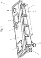
- a screening machine 1 for screening a powdered material comprises an inlet 2 for feeding the powdered material onto a screen which is held on a support 8 .
- the screening machine 1 has a housing with a lower part 3 for collecting the screened grain, with an outlet 10 for the grain being provided on the lower part 3 .
- the lower part 3 comprises a connecting part 4 which is connected to a conveyor drive in order to move the housing of the screening machine 1 and to convey the powdered material on the screen from an inlet 2 to an outlet 9 for the oversize.
- a conveyor drive can promote the powdery material step by step on the screen.
- the screening machine 1 comprises a cover or upper part 5 which is arranged on the lower part 3 and on which one or more viewing windows 6 are provided.
- the upper part 5 is arranged in a sealed manner on the lower part 3, and the interior of the housing can be filled with a gas, in particular an inert gas.
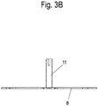
- a sound conductor 11 is also passed through the upper part 5 and is intended to clean the screen and is connected to an ultrasonic converter 7 .
- the sound conductor 11 is passed through the upper part 5 in a decoupled manner and is firmly connected to the carrier 8 .
- the ultrasonic converter 7 can thus move the carrier 8 via the sound conductor 11, on which the screen is clamped, with the movements of the ultrasonic converter 7 and those of the conveyor drive being superimposed.
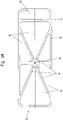
- the carrier 8 is shown in detail.
- the carrier 8 is formed in one piece and has a thickness of between 1.5 mm and 5 mm, in particular 2 mm and 4 mm.
- the carrier 8 comprises an outer frame 13 which is rectangular in plan view and is at least twice as long as it is wide.
- a holder 12 is provided in a central area of the frame 13 , which is designed as a node and is connected to the sound conductor 11 .
- the holder 12 is arranged in the center of the frame 13 and is connected to the frame 13 via a multiplicity of struts 14 arranged in a star shape.
- struts 14 are provided by the holder 12 with the frame 13, it being possible for the number of struts 14 to be varied, for example four to eight struts 14 can be provided.
- the screen is stretched on the carrier 8, in particular glued, and thereby fixed both to the struts 14 and to the frame 13.
- the screen does not cover the carrier 8 completely, but an opening 16 is formed on one end face, which is delimited by a cross brace 17 on the side facing the holder 12 .
- a front end of the screen is fixed to this cross brace 17 .
- the powdered material is first entered into the inlet 2 and conveyed, for example, in an inert gas atmosphere. Then the powdery material is conveyed over the sieve by the conveyor drive to the opening 16, with the smaller grain size falling through the sieve and only the larger oversize grain being conveyed into the opening 16 to the outlet 9 for the oversize grain.
- the sieve is easily clogged during the sieving process, so that cleaning is generated by the ultrasonic converter 7 by the carrier 8 being moved over the ultrasonic converter 7, which leads to a cleaning of the sieve.
- the grain that has fallen through the sieve is then further processed via the outlet 10 .
- the carrier 8 with the sieve is preferably aligned inclined to the horizontal, so that the powdered material is conveyed uphill on the sieve.
- the angle of inclination of the carrier with the screen is, for example, in a range from 1° to 5°, preferably 2° to 4°.
- Such a screening machine can be used, for example, to separate metal powder, for example for 3D printing applications, also in the context of additive manufacturing.
- the screening machine can also be used in other areas.
Description
Die vorliegende Erfindung betrifft eine Siebmaschine zum Trennen eines pulverförmigen Materials, nach dem Oberbegriff des Anspruches 1 und ein Verfahren zum Sieben von pulverförmigem Material in einer Siebmaschine.The present invention relates to a screening machine for separating a powdered material, according to the preamble of claim 1, and a method for screening powdered material in a screening machine.
Die
In der
Es ist daher Aufgabe der vorliegenden Erfindung, eine Siebmaschine zu schaffen, mittels der eine verbesserte Abreinigung eines Siebes ermöglicht wird, und ein Verfahren zum Sieben von pulverförmigem Material zu schaffen, das ein effektives Sieben ermöglicht.It is therefore the object of the present invention to create a screening machine by means of which improved cleaning of a screen is made possible, and to create a method for screening powdered material which enables effective screening.
Diese Aufgabe wird mit einer Siebmaschine mit den Merkmalen des Anspruches 1 sowie einem Verfahren mit den Merkmalen des Anspruches 11 gelöst.This object is achieved with a screening machine having the features of claim 1 and a method having the features of
Bei der erfindungsgemäßen Siebmaschine wird das pulverförmige Material auf ein Sieb gegeben, das an einem Träger gespannt ist, wobei der Träger einen Rahmen und einen innerhalb des Rahmens angeordneten Halter aufweist, an dem ein Ultraschallkonverter über einen Schallleiter angeschlossen ist, wobei der Halter über mehrere Streben mit dem Rahmen verbunden ist. Durch diese Gestaltung des Trägers kann der Ultraschallkonverter das Sieb in einer größeren Fläche reinigen, da der Träger angetrieben wird und die Bewegung des Trägers über verschiedene Bereiche in das Sieb eingeleitet wird. Dadurch kann der Ultraschallkonverter das Sieb großflächig abreinigen.In the screening machine according to the invention, the powdery material is placed on a screen that is stretched on a carrier, the carrier having a frame and a holder arranged within the frame, to which an ultrasonic converter is connected via a sound conductor, the holder having several struts connected to the frame. This design of the carrier allows the ultrasonic converter to clean the screen over a larger area, since the carrier is driven and the movement of the Carrier is introduced into the screen via different areas. This allows the ultrasonic converter to clean the screen over a large area.
Der Träger ist vorzugsweise plattenförmig mit Öffnungen ausgebildet, an denen das Sieb zumindest teilweise gespannt ist. Das Sieb und der Träger können dabei rechteckförmig in Draufsicht ausgebildet sein, wobei der Träger das Sieb vorzugsweise an einer Stirnseite überragt, und an dem überragenden Abschnitt eine Öffnung zum Entsorgen des Überkorns zu dem Auslass für das Überkorn ausgebildet ist.The carrier is preferably designed in the form of a plate with openings on which the screen is at least partially stretched. The sieve and the carrier can be rectangular in plan view, the carrier preferably protruding beyond the sieve at one end, and an opening for disposing of the oversize particles to the outlet for the oversize particles is formed on the protruding section.
Für eine einfache Herstellung des Trägers ist dieser erfindungsgemäß einstückig ausgebildet, beispielsweise aus einem Metallblech, insbesondere aus einem Stahlblech. Die Dicke des Trägers kann beispielsweise zwischen 1,5 mm bis 5 mm, vorzugsweise 2 bis 4 mm, betragen, so dass über den Träger das Sieb stabil abgestützt ist. Das Sieb ist durch Verkleben an dem Träger festgelegt .For easy production of the carrier, it is designed in one piece according to the invention, for example from a metal sheet, in particular from a steel sheet. The thickness of the support can be, for example, between 1.5 mm and 5 mm, preferably 2 to 4 mm, so that the screen is stably supported by the support. The screen is fixed to the support by gluing.
Von dem mittigen Halter erstrecken sich vorzugsweise mehrere Streben sternförmig zu dem Rahmen, insbesondere können vier bis acht Streben zur Verbindung des mittigen Halters mit dem äußeren Rahmen vorgesehen sein. Der Halter kann dabei exakt an einem symmetrischen Mittelpunkt des Trägers vorgesehen sein, aber auch eine außermittige Anordnung innerhalb des Rahmens ist möglich.A plurality of struts preferably extend in a star shape from the central holder to the frame; in particular, four to eight struts can be provided for connecting the central holder to the outer frame. The holder can be provided exactly at a symmetrical center point of the carrier, but an eccentric arrangement within the frame is also possible.
Die Siebmaschine umfasst bevorzugt zusätzlich einen Förderantrieb, um das pulverförmige Material auf dem Sieb von dem Einlass zu dem ersten Auslass für das Überkorn zu fördern. Der Förderantrieb kann dabei ein Gehäuse der Siebmaschine bewegen, um das pulverförmige Material auf dem Sieb in kleinen Schritten vom Einlass zum ersten Auslass zu fördern, sofern es nicht durch das Sieb fällt. Dadurch überlagern sich die Bewegungen des Förderantriebes und die Bewegung des Siebes durch den Ultraschallkonverter zum Abreinigen des Siebes.The screening machine preferably additionally comprises a conveyor drive in order to convey the powdery material on the screen from the inlet to the first outlet for the oversized grain. In this case, the conveyor drive can move a housing of the screening machine in order to convey the powdery material on the screen in small steps from the inlet to the first outlet, provided it does not fall through the screen. As a result, the movements of the conveyor drive and the movement of the screen by the ultrasonic converter for cleaning the screen are superimposed.
Das Sieb kann beispielsweise zum Trennen von pulverförmigem Material, insbesondere Metallpulver, beispielsweise Aluminiumpulver für 3D-Drucker, ausgebildet sein. Die Öffnungen des Siebes können in beide Richtungen eine Erstreckung von beispielsweise zwischen 10 µm bis 200 µm, insbesondere zwischen 50 µm bis 100 µm, besitzen, wobei die Größe der Öffnungen allerdings vom konkreten Anwendungsfall abhängt.The sieve can, for example, be designed to separate powdered material, in particular metal powder, for example aluminum powder for 3D printers. The openings of the screen can extend in both directions from, for example, between 10 μm and 200 μm, in particular between 50 μm and 100 μm, although the size of the openings depends on the specific application.
Bei dem erfindungsgemäßen Verfahren wird das pulverförmige Material zu einem Einlass zugeführt und auf ein an einem Träger gehaltenes Sieb gegeben. Das Sieb wird zum Fördern des pulverförmigen Materials bewegt, wobei zusätzlich das Sieb durch einen Ultraschallkonverter gereinigt wird. Der Ultraschallkonverter ist in Draufsicht in einem mittleren Bereich an einem Halter mit dem Träger verbunden, so dass das pulverförmige Material aufgeteilt wird. Das durch das Sieb gefallene Gutkorn wird an einem zweiten Auslass entfernt, während das über das Sieb geförderte Überkorn an einem ersten Auslass entfernt wird.In the method according to the invention, the powdery material is fed to an inlet and placed on a sieve held on a support. The sieve is moved to convey the powdered material, with the sieve also being cleaned by an ultrasonic converter. In a plan view, the ultrasonic converter is connected to the carrier in a central region on a holder, so that the powdered material is divided. The acceptable grain that has fallen through the screen is removed at a second outlet, while the oversize grain conveyed through the screen is removed at a first outlet.
Die Erfindung wird nachfolgend anhand eines Ausführungsbeispiels mit Bezug auf die beigefügten Zeichnungen näher erläutert. Es zeigen:
- Figur 1
- eine perspektivische Ansicht einer erfindungsgemäßen Siebmaschine;
Figur 2- eine Schnittansicht durch die Siebmaschine der
Figur 1 , und - Figuren 3A und 3B
- zwei Ansichten eines Trägers der Siebmaschine der Figur 1.
- figure 1
- a perspective view of a screening machine according to the invention;
- figure 2
- a sectional view through the screening machine
figure 1 , and - Figures 3A and 3B
- two views of a carrier of the screening machine of Figure 1.
Eine Siebmaschine 1 zum Sieben eines pulverförmigen Materials umfasst einen Einlass 2 zur Aufgabe des pulverförmigen Materials auf ein Sieb, das an einem Träger 8 gehalten ist. Die Siebmaschine 1 besitzt ein Gehäuse mit einem Unterteil 3 zum Auffangen des gesiebten Gutkorns, wobei an dem Unterteil 3 ein Auslass 10 für das Gutkorn vorgesehen ist. Das Unterteil 3 umfasst ein Verbindungsteil 4, das mit einem Förderantrieb verbunden ist, um das Gehäuse der Siebmaschine 1 zu bewegen und das pulverförmige Material auf dem Sieb von einem Einlass 2 zu einem Auslass 9 für das Überkorn zu fördern. Ein solcher Förderantrieb kann das pulverförmige Material schrittweise auf dem Sieb fördern.A screening machine 1 for screening a powdered material comprises an
Die Siebmaschine 1 umfasst eine auf dem Unterteil 3 angeordnete Abdeckung oder Oberteil 5, an der ein oder mehrere Sichtfenster 6 vorgesehen sind. Das Oberteil 5 ist abgedichtet an dem Unterteil 3 angeordnet, und der Innenraum des Gehäuses kann mit einem Gas, insbesondere einem Inertgas, befüllt sein.The screening machine 1 comprises a cover or
Durch das Oberteil 5 ist ferner ein Schallleiter 11 durchgeführt, der das Sieb abreinigen soll und mit einem Ultraschallkonverter 7 verbunden ist. Hierfür ist der Schallleiter 11 entkoppelt durch das Oberteil 5 durchgeführt und mit dem Träger 8 fest verbunden. Der Ultraschallkonverter 7 kann somit über den Schallleiter 11 den Träger 8 bewegen, an dem das Sieb aufgespannt ist, wobei sich die Bewegungen des Ultraschallkonverters 7 und die des Förderantriebs überlagern.A
In den
Das pulverförmige Material wird zunächst in den Einlass 2 eingegeben, und beispielsweise in einer Inertgas-Atmosphäre gefördert. Dann wird das pulverförmige Material über das Sieb durch den Förderantrieb zu der Öffnung 16 gefördert, wobei das kleinere Gutkorn durch das Sieb fällt und nur das größere Überkorn in die Öffnung 16 zu dem Auslass 9 für das Überkorn gefördert wird. Das Sieb wird während des Siebvorganges leicht verstopft, so dass durch den Ultraschallkonverter 7 eine Abreinigung erzeugt wird, indem der Träger 8 über den Ultraschallkonverter 7 bewegt wird, was zu einer Reinigung des Siebes führt. Das durch das Sieb gefallene Gutkorn wird dann über den Auslass 10 weiterverarbeitet.The powdered material is first entered into the
Der Träger 8 mit dem Sieb ist vorzugsweise geneigt zur Horizontalen ausgerichtet, so dass das pulverförmige Material auf dem Sieb bergauf gefördert wird. Der Neigungswinkel des Trägers mit dem Sieb liegt beispielsweise in einem Bereich von 1° bis 5°, vorzugsweise 2° bis 4°.The
Eine solche Siebmaschine kann beispielsweise zum Trennen von Metallpulver eingesetzt werden, beispielsweise für 3D-Druckanwendungen, auch im Rahmen der additiven Fertigung. Auch in anderen Bereichen kann die Siebmaschine eingesetzt werden.Such a screening machine can be used, for example, to separate metal powder, for example for 3D printing applications, also in the context of additive manufacturing. The screening machine can also be used in other areas.
- 11
- Siebmaschinescreening machine
- 22
- Einlassinlet
- 33
- Unterteillower part
- 44
- Verbindungsteilconnection part
- 55
- Oberteiltop
- 66
- Sichtfensterviewing window
- 77
- Ultraschallkonverterultrasonic converter
- 88th
- Trägercarrier
- 99
- Auslassoutlet
- 1010
- Auslassoutlet
- 1111
- Schallleitersound conductor
- 1212
- Halterholder
- 1313
- Rahmenframe
- 1414
- Strebestrut
- 1616
- Öffnungopening
- 1717
- Querstrebecrossbar
Claims (11)
- Sieve machine (1) for separating a powder-form material, comprising an inlet (2) for the powder-form material, a sieve held on a carrier (8), a first outlet (9) for the oversize grain and a second outlet (10) for the good grain which has passed through the sieve, wherein the carrier (8) comprises a frame (13) on which the sieve is clamped, and the carrier (8) is movable via an ultrasonic converter (7), wherein the ultrasonic converter (7) is connected to the carrier (8) within the frame (13) via an acoustic conductor (11) on a holder (12) and the holder (12) is connected to the frame (13) via a plurality of struts (14), characterized in that the carrier (8) is integrally formed and an opening (16) is formed in the carrier (8) through which the oversize grain can be conveyed to the first outlet (9) and the sieve is fixed to the carrier (8) by bonding.
- Sieve machine according to claim 1, characterized in that the carrier (8) is of plate-shaped design having openings at which the sieve is at least partially clamped.
- Sieve machine according to claim 1 or 2, characterized in that four to eight struts (40) are connected to the frame (13) in a star shape by the holder (12).
- Sieve machine according to one of the preceding claims, characterized in that the carrier (8) is rectangular in plan view.
- Sieve machine according to one of the preceding claims, characterized in that the carrier (8) is made of a metal sheet.
- Sieve machine according to one of the preceding claims, characterized in that a conveyor drive is provided to convey the powder-form material on the sieve linearly from the inlet (2) to the first outlet (9).
- Sieve machine according to one of the preceding claims, characterized in that the sieve is arranged inclined to the horizontal, preferably at an angle between 1° and 5°.
- Sieve machine according to one of the preceding claims, characterized in that the carrier (8) has a thickness between 2 mm to 5 mm.
- Sieve machine according to one of the preceding claims, characterized in that the sieve is arranged in a housing and the ultrasonic converter (7) is passed through an upper cover (5) of the housing.
- Sieve machine according to one of the preceding claims, characterized in that the sieve has openings between 10 µm and 200 µm, in particular 50 µm to 100 µm.
- Method for sieving powder-form material in a sieve machine (1) according to claim 1, comprising the following steps:- feeding powder-form material at an inlet (2) onto a sieve held on an integral carrier (8);- moving the sieve to convey the powder-form material along the sieve to an outlet opening (16) in the carrier (8);- cleaning the sieve by an ultrasonic converter (7) connected to the carrier (8) at a central region on a holder (12) in plan view, and- removing the oversize grain at a first outlet (9) and the good grain that has fallen through the sieve at a second outlet (10).
Applications Claiming Priority (1)
| Application Number | Priority Date | Filing Date | Title |
|---|---|---|---|
| DE102018115831.9A DE102018115831A1 (en) | 2018-06-29 | 2018-06-29 | Screening machine and method for screening powdered material |
Publications (2)
| Publication Number | Publication Date |
|---|---|
| EP3586983A1 EP3586983A1 (en) | 2020-01-01 |
| EP3586983B1 true EP3586983B1 (en) | 2022-12-07 |
Family
ID=66690238
Family Applications (1)
| Application Number | Title | Priority Date | Filing Date |
|---|---|---|---|
| EP19177875.2A Active EP3586983B1 (en) | 2018-06-29 | 2019-06-03 | Sieve machine and method for sieving powder-form material |
Country Status (2)
| Country | Link |
|---|---|
| EP (1) | EP3586983B1 (en) |
| DE (1) | DE102018115831A1 (en) |
Citations (5)
| Publication number | Priority date | Publication date | Assignee | Title |
|---|---|---|---|---|
| WO2004050263A1 (en) | 2002-12-02 | 2004-06-17 | Russell Finex Limited | Sieving apparatus |
| US6945168B1 (en) * | 2004-04-29 | 2005-09-20 | Niswonger John O H | Apparatus and method for a silkscreen |
| DE102006047592A1 (en) | 2006-10-05 | 2008-04-10 | Artech Systems Ag | Apparatus for exciting a sieve fabric enclosed in a sieve frame by means of ultrasound |
| JP2011245446A (en) | 2010-05-28 | 2011-12-08 | Tokyo Seifunki Seisakusho:Kk | Sieving device |
| DE202014103239U1 (en) | 2013-07-31 | 2014-08-18 | Si Lin Yu | Ultrasonic vibratory screening |
Family Cites Families (2)
| Publication number | Priority date | Publication date | Assignee | Title |
|---|---|---|---|---|
| GB1094218A (en) * | 1963-12-17 | 1967-12-06 | Choompa Kogyo Kabushiki Kaisha | Screening method for pulverized particles and apparatus therefor |
| DE4418175C5 (en) * | 1993-05-26 | 2006-02-16 | Telsonic Ag | Apparatus and method for sifting, classifying, sifting, filtering or sorting fabrics |
-
2018
- 2018-06-29 DE DE102018115831.9A patent/DE102018115831A1/en active Pending
-
2019
- 2019-06-03 EP EP19177875.2A patent/EP3586983B1/en active Active
Patent Citations (5)
| Publication number | Priority date | Publication date | Assignee | Title |
|---|---|---|---|---|
| WO2004050263A1 (en) | 2002-12-02 | 2004-06-17 | Russell Finex Limited | Sieving apparatus |
| US6945168B1 (en) * | 2004-04-29 | 2005-09-20 | Niswonger John O H | Apparatus and method for a silkscreen |
| DE102006047592A1 (en) | 2006-10-05 | 2008-04-10 | Artech Systems Ag | Apparatus for exciting a sieve fabric enclosed in a sieve frame by means of ultrasound |
| JP2011245446A (en) | 2010-05-28 | 2011-12-08 | Tokyo Seifunki Seisakusho:Kk | Sieving device |
| DE202014103239U1 (en) | 2013-07-31 | 2014-08-18 | Si Lin Yu | Ultrasonic vibratory screening |
Non-Patent Citations (3)
| Title |
|---|
| ANONYMOUS: "Compact screening machine | assonic Dorstener Siebtechnik GmbH | Eddy current screening machine with ultrasound | ATEX rotary screening machine", 10 December 2017 (2017-12-10), XP093130976, Retrieved from the Internet <URL:https://web.archive.org/web/20171210130911/http://www.assonic.de:80/kompakt-siebmaschine/> |
| ANONYMOUS: "Kompaktsiebmaschine ATEX-Ausfuhrung/ ATEX-inertisierbare Ausfuhrung, TypNr.: KSM 500", BETRIEBSANLEITUNG V00.03, ASSONIC, 17 December 2001 (2001-12-17), XP093130971 |
| ANONYMOUS: "Werbung assonic", ADDITIVE FERTIGUNG, 3 November 2017 (2017-11-03), pages 39, XP093130957 |
Also Published As
| Publication number | Publication date |
|---|---|
| DE102018115831A1 (en) | 2020-01-02 |
| EP3586983A1 (en) | 2020-01-01 |
Similar Documents
| Publication | Publication Date | Title |
|---|---|---|
| DE69925750T2 (en) | SEVEN GROUND FOR SLATE SHAKER | |
| EP0652810B1 (en) | Process and device for sifting, sorting, screening, filtering or sizing substances | |
| EP1398085B1 (en) | Multi-deck screening machine | |
| DE19646229A1 (en) | Sieve assembly, especially for vibrating sieve processes, | |
| DE4418175C5 (en) | Apparatus and method for sifting, classifying, sifting, filtering or sorting fabrics | |
| DE112017002332B4 (en) | SIDE FINE GRAIN GUTTERS OF A TURNTAKER | |
| EP3586983B1 (en) | Sieve machine and method for sieving powder-form material | |
| DE102012206347A1 (en) | Screening apparatus has wire portions whose parameters are set different from each other, besides different alignment of wire portions with respect to horizontal region | |
| DE3601671C2 (en) | Device and method for screening or classifying piles | |
| EP0316461B1 (en) | Vibratory screen | |
| EP1400288B1 (en) | Device for separating coarse and fine particles | |
| DE3505502A1 (en) | TOBACCO CLASSIFIER | |
| DE202018105632U1 (en) | screening machine | |
| EP3275562B1 (en) | Finger screen | |
| DE102006037638A1 (en) | Excitation of solids e.g. powders, sieves, surfaces and tubes with ultrasound to minimize surface friction during relative movement, first applies ultrasonic tuning to find optimum working point | |
| DE102015221273A1 (en) | Water jet cutting process, water jet cutting machine and workpiece holder | |
| DE19828914C2 (en) | Ultrasonic screening device | |
| EP1224984B1 (en) | Sieve and plansifter | |
| DE2356525A1 (en) | DEVICE FOR MECHANICAL SEPARATION OF THE SMALLEST PARTICLES FROM A SCREEN MATERIAL | |
| DE19517850C2 (en) | Screening machine for pre-sorting material mixtures | |
| DE102007016225A1 (en) | Device for conveying and dedusting tablets or similar compacts from a tablet press | |
| DE1257548B (en) | Vibrator screen | |
| DE2153710C3 (en) | Waste separator for green beans | |
| DE3114573A1 (en) | "VIBRATION SCREEN WITH SELF-SUPPORTING SCREEN WIRE MESH" | |
| EP3248695A1 (en) | Screening device |
Legal Events
| Date | Code | Title | Description |
|---|---|---|---|
| PUAI | Public reference made under article 153(3) epc to a published international application that has entered the european phase |
Free format text: ORIGINAL CODE: 0009012 |
|
| STAA | Information on the status of an ep patent application or granted ep patent |
Free format text: STATUS: THE APPLICATION HAS BEEN PUBLISHED |
|
| AK | Designated contracting states |
Kind code of ref document: A1 Designated state(s): AL AT BE BG CH CY CZ DE DK EE ES FI FR GB GR HR HU IE IS IT LI LT LU LV MC MK MT NL NO PL PT RO RS SE SI SK SM TR |
|
| AX | Request for extension of the european patent |
Extension state: BA ME |
|
| STAA | Information on the status of an ep patent application or granted ep patent |
Free format text: STATUS: REQUEST FOR EXAMINATION WAS MADE |
|
| 17P | Request for examination filed |
Effective date: 20200330 |
|
| RBV | Designated contracting states (corrected) |
Designated state(s): AL AT BE BG CH CY CZ DE DK EE ES FI FR GB GR HR HU IE IS IT LI LT LU LV MC MK MT NL NO PL PT RO RS SE SI SK SM TR |
|
| STAA | Information on the status of an ep patent application or granted ep patent |
Free format text: STATUS: EXAMINATION IS IN PROGRESS |
|
| 17Q | First examination report despatched |
Effective date: 20220217 |
|
| GRAP | Despatch of communication of intention to grant a patent |
Free format text: ORIGINAL CODE: EPIDOSNIGR1 |
|
| STAA | Information on the status of an ep patent application or granted ep patent |
Free format text: STATUS: GRANT OF PATENT IS INTENDED |
|
| INTG | Intention to grant announced |
Effective date: 20220914 |
|
| GRAS | Grant fee paid |
Free format text: ORIGINAL CODE: EPIDOSNIGR3 |
|
| GRAA | (expected) grant |
Free format text: ORIGINAL CODE: 0009210 |
|
| STAA | Information on the status of an ep patent application or granted ep patent |
Free format text: STATUS: THE PATENT HAS BEEN GRANTED |
|
| AK | Designated contracting states |
Kind code of ref document: B1 Designated state(s): AL AT BE BG CH CY CZ DE DK EE ES FI FR GB GR HR HU IE IS IT LI LT LU LV MC MK MT NL NO PL PT RO RS SE SI SK SM TR |
|
| REG | Reference to a national code |
Ref country code: GB Ref legal event code: FG4D Free format text: NOT ENGLISH |
|
| REG | Reference to a national code |
Ref country code: CH Ref legal event code: EP Ref country code: AT Ref legal event code: REF Ref document number: 1535985 Country of ref document: AT Kind code of ref document: T Effective date: 20221215 |
|
| REG | Reference to a national code |
Ref country code: DE Ref legal event code: R096 Ref document number: 502019006461 Country of ref document: DE |
|
| REG | Reference to a national code |
Ref country code: IE Ref legal event code: FG4D Free format text: LANGUAGE OF EP DOCUMENT: GERMAN |
|
| REG | Reference to a national code |
Ref country code: LT Ref legal event code: MG9D |
|
| REG | Reference to a national code |
Ref country code: NL Ref legal event code: MP Effective date: 20221207 |
|
| PG25 | Lapsed in a contracting state [announced via postgrant information from national office to epo] |
Ref country code: SE Free format text: LAPSE BECAUSE OF FAILURE TO SUBMIT A TRANSLATION OF THE DESCRIPTION OR TO PAY THE FEE WITHIN THE PRESCRIBED TIME-LIMIT Effective date: 20221207 Ref country code: NO Free format text: LAPSE BECAUSE OF FAILURE TO SUBMIT A TRANSLATION OF THE DESCRIPTION OR TO PAY THE FEE WITHIN THE PRESCRIBED TIME-LIMIT Effective date: 20230307 Ref country code: LT Free format text: LAPSE BECAUSE OF FAILURE TO SUBMIT A TRANSLATION OF THE DESCRIPTION OR TO PAY THE FEE WITHIN THE PRESCRIBED TIME-LIMIT Effective date: 20221207 Ref country code: FI Free format text: LAPSE BECAUSE OF FAILURE TO SUBMIT A TRANSLATION OF THE DESCRIPTION OR TO PAY THE FEE WITHIN THE PRESCRIBED TIME-LIMIT Effective date: 20221207 Ref country code: ES Free format text: LAPSE BECAUSE OF FAILURE TO SUBMIT A TRANSLATION OF THE DESCRIPTION OR TO PAY THE FEE WITHIN THE PRESCRIBED TIME-LIMIT Effective date: 20221207 |
|
| PG25 | Lapsed in a contracting state [announced via postgrant information from national office to epo] |
Ref country code: RS Free format text: LAPSE BECAUSE OF FAILURE TO SUBMIT A TRANSLATION OF THE DESCRIPTION OR TO PAY THE FEE WITHIN THE PRESCRIBED TIME-LIMIT Effective date: 20221207 Ref country code: PL Free format text: LAPSE BECAUSE OF FAILURE TO SUBMIT A TRANSLATION OF THE DESCRIPTION OR TO PAY THE FEE WITHIN THE PRESCRIBED TIME-LIMIT Effective date: 20221207 Ref country code: LV Free format text: LAPSE BECAUSE OF FAILURE TO SUBMIT A TRANSLATION OF THE DESCRIPTION OR TO PAY THE FEE WITHIN THE PRESCRIBED TIME-LIMIT Effective date: 20221207 Ref country code: HR Free format text: LAPSE BECAUSE OF FAILURE TO SUBMIT A TRANSLATION OF THE DESCRIPTION OR TO PAY THE FEE WITHIN THE PRESCRIBED TIME-LIMIT Effective date: 20221207 Ref country code: GR Free format text: LAPSE BECAUSE OF FAILURE TO SUBMIT A TRANSLATION OF THE DESCRIPTION OR TO PAY THE FEE WITHIN THE PRESCRIBED TIME-LIMIT Effective date: 20230308 |
|
| PG25 | Lapsed in a contracting state [announced via postgrant information from national office to epo] |
Ref country code: NL Free format text: LAPSE BECAUSE OF FAILURE TO SUBMIT A TRANSLATION OF THE DESCRIPTION OR TO PAY THE FEE WITHIN THE PRESCRIBED TIME-LIMIT Effective date: 20221207 |
|
| PG25 | Lapsed in a contracting state [announced via postgrant information from national office to epo] |
Ref country code: SM Free format text: LAPSE BECAUSE OF FAILURE TO SUBMIT A TRANSLATION OF THE DESCRIPTION OR TO PAY THE FEE WITHIN THE PRESCRIBED TIME-LIMIT Effective date: 20221207 Ref country code: RO Free format text: LAPSE BECAUSE OF FAILURE TO SUBMIT A TRANSLATION OF THE DESCRIPTION OR TO PAY THE FEE WITHIN THE PRESCRIBED TIME-LIMIT Effective date: 20221207 Ref country code: PT Free format text: LAPSE BECAUSE OF FAILURE TO SUBMIT A TRANSLATION OF THE DESCRIPTION OR TO PAY THE FEE WITHIN THE PRESCRIBED TIME-LIMIT Effective date: 20230410 Ref country code: EE Free format text: LAPSE BECAUSE OF FAILURE TO SUBMIT A TRANSLATION OF THE DESCRIPTION OR TO PAY THE FEE WITHIN THE PRESCRIBED TIME-LIMIT Effective date: 20221207 Ref country code: CZ Free format text: LAPSE BECAUSE OF FAILURE TO SUBMIT A TRANSLATION OF THE DESCRIPTION OR TO PAY THE FEE WITHIN THE PRESCRIBED TIME-LIMIT Effective date: 20221207 |
|
| PG25 | Lapsed in a contracting state [announced via postgrant information from national office to epo] |
Ref country code: SK Free format text: LAPSE BECAUSE OF FAILURE TO SUBMIT A TRANSLATION OF THE DESCRIPTION OR TO PAY THE FEE WITHIN THE PRESCRIBED TIME-LIMIT Effective date: 20221207 Ref country code: IS Free format text: LAPSE BECAUSE OF FAILURE TO SUBMIT A TRANSLATION OF THE DESCRIPTION OR TO PAY THE FEE WITHIN THE PRESCRIBED TIME-LIMIT Effective date: 20230407 Ref country code: AL Free format text: LAPSE BECAUSE OF FAILURE TO SUBMIT A TRANSLATION OF THE DESCRIPTION OR TO PAY THE FEE WITHIN THE PRESCRIBED TIME-LIMIT Effective date: 20221207 |
|
| REG | Reference to a national code |
Ref country code: DE Ref legal event code: R026 Ref document number: 502019006461 Country of ref document: DE |
|
| PLBI | Opposition filed |
Free format text: ORIGINAL CODE: 0009260 |
|
| PLAX | Notice of opposition and request to file observation + time limit sent |
Free format text: ORIGINAL CODE: EPIDOSNOBS2 |
|
| 26 | Opposition filed |
Opponent name: ASSONIC DORSTENER SIEBTECHNIK GMBH Effective date: 20230907 |
|
| PG25 | Lapsed in a contracting state [announced via postgrant information from national office to epo] |
Ref country code: DK Free format text: LAPSE BECAUSE OF FAILURE TO SUBMIT A TRANSLATION OF THE DESCRIPTION OR TO PAY THE FEE WITHIN THE PRESCRIBED TIME-LIMIT Effective date: 20221207 |
|
| PGFP | Annual fee paid to national office [announced via postgrant information from national office to epo] |
Ref country code: GB Payment date: 20230525 Year of fee payment: 5 Ref country code: CH Payment date: 20230702 Year of fee payment: 5 Ref country code: IT Payment date: 20230630 Year of fee payment: 5 |
|
| PG25 | Lapsed in a contracting state [announced via postgrant information from national office to epo] |
Ref country code: SI Free format text: LAPSE BECAUSE OF FAILURE TO SUBMIT A TRANSLATION OF THE DESCRIPTION OR TO PAY THE FEE WITHIN THE PRESCRIBED TIME-LIMIT Effective date: 20221207 |
|
| PGFP | Annual fee paid to national office [announced via postgrant information from national office to epo] |
Ref country code: DE Payment date: 20230727 Year of fee payment: 5 |
|
| PLBB | Reply of patent proprietor to notice(s) of opposition received |
Free format text: ORIGINAL CODE: EPIDOSNOBS3 |
|
| PG25 | Lapsed in a contracting state [announced via postgrant information from national office to epo] |
Ref country code: MC Free format text: LAPSE BECAUSE OF FAILURE TO SUBMIT A TRANSLATION OF THE DESCRIPTION OR TO PAY THE FEE WITHIN THE PRESCRIBED TIME-LIMIT Effective date: 20221207 |
|
| PG25 | Lapsed in a contracting state [announced via postgrant information from national office to epo] |
Ref country code: MC Free format text: LAPSE BECAUSE OF FAILURE TO SUBMIT A TRANSLATION OF THE DESCRIPTION OR TO PAY THE FEE WITHIN THE PRESCRIBED TIME-LIMIT Effective date: 20221207 |
|
| REG | Reference to a national code |
Ref country code: BE Ref legal event code: MM Effective date: 20230630 |
|
| PG25 | Lapsed in a contracting state [announced via postgrant information from national office to epo] |
Ref country code: LU Free format text: LAPSE BECAUSE OF NON-PAYMENT OF DUE FEES Effective date: 20230603 |
|
| REG | Reference to a national code |
Ref country code: IE Ref legal event code: MM4A |
|
| PG25 | Lapsed in a contracting state [announced via postgrant information from national office to epo] |
Ref country code: LU Free format text: LAPSE BECAUSE OF NON-PAYMENT OF DUE FEES Effective date: 20230603 |
|
| PG25 | Lapsed in a contracting state [announced via postgrant information from national office to epo] |
Ref country code: IE Free format text: LAPSE BECAUSE OF NON-PAYMENT OF DUE FEES Effective date: 20230603 |