EP3586004B1 - Verfahren zur herstellung von gehäusen für rollenstössel - Google Patents
Verfahren zur herstellung von gehäusen für rollenstössel Download PDFInfo
- Publication number
- EP3586004B1 EP3586004B1 EP18704137.1A EP18704137A EP3586004B1 EP 3586004 B1 EP3586004 B1 EP 3586004B1 EP 18704137 A EP18704137 A EP 18704137A EP 3586004 B1 EP3586004 B1 EP 3586004B1
- Authority
- EP
- European Patent Office
- Prior art keywords
- bar profile
- housings
- semi
- roller
- bore
- Prior art date
- Legal status (The legal status is an assumption and is not a legal conclusion. Google has not performed a legal analysis and makes no representation as to the accuracy of the status listed.)
- Active
Links
Images

Classifications
-
- F—MECHANICAL ENGINEERING; LIGHTING; HEATING; WEAPONS; BLASTING
- F02—COMBUSTION ENGINES; HOT-GAS OR COMBUSTION-PRODUCT ENGINE PLANTS
- F02M—SUPPLYING COMBUSTION ENGINES IN GENERAL WITH COMBUSTIBLE MIXTURES OR CONSTITUENTS THEREOF
- F02M59/00—Pumps specially adapted for fuel-injection and not provided for in groups F02M39/00 -F02M57/00, e.g. rotary cylinder-block type of pumps
- F02M59/02—Pumps specially adapted for fuel-injection and not provided for in groups F02M39/00 -F02M57/00, e.g. rotary cylinder-block type of pumps of reciprocating-piston or reciprocating-cylinder type
- F02M59/10—Pumps specially adapted for fuel-injection and not provided for in groups F02M39/00 -F02M57/00, e.g. rotary cylinder-block type of pumps of reciprocating-piston or reciprocating-cylinder type characterised by the piston-drive
- F02M59/102—Mechanical drive, e.g. tappets or cams
-
- F—MECHANICAL ENGINEERING; LIGHTING; HEATING; WEAPONS; BLASTING
- F04—POSITIVE - DISPLACEMENT MACHINES FOR LIQUIDS; PUMPS FOR LIQUIDS OR ELASTIC FLUIDS
- F04B—POSITIVE-DISPLACEMENT MACHINES FOR LIQUIDS; PUMPS
- F04B1/00—Multi-cylinder machines or pumps characterised by number or arrangement of cylinders
- F04B1/04—Multi-cylinder machines or pumps characterised by number or arrangement of cylinders having cylinders in star- or fan-arrangement
- F04B1/0404—Details or component parts
- F04B1/0426—Arrangements for pressing the pistons against the actuated cam; Arrangements for connecting the pistons to the actuated cam
-
- F—MECHANICAL ENGINEERING; LIGHTING; HEATING; WEAPONS; BLASTING
- F04—POSITIVE - DISPLACEMENT MACHINES FOR LIQUIDS; PUMPS FOR LIQUIDS OR ELASTIC FLUIDS
- F04B—POSITIVE-DISPLACEMENT MACHINES FOR LIQUIDS; PUMPS
- F04B1/00—Multi-cylinder machines or pumps characterised by number or arrangement of cylinders
- F04B1/04—Multi-cylinder machines or pumps characterised by number or arrangement of cylinders having cylinders in star- or fan-arrangement
- F04B1/0404—Details or component parts
- F04B1/0439—Supporting or guiding means for the pistons
-
- F—MECHANICAL ENGINEERING; LIGHTING; HEATING; WEAPONS; BLASTING
- F02—COMBUSTION ENGINES; HOT-GAS OR COMBUSTION-PRODUCT ENGINE PLANTS
- F02M—SUPPLYING COMBUSTION ENGINES IN GENERAL WITH COMBUSTIBLE MIXTURES OR CONSTITUENTS THEREOF
- F02M2200/00—Details of fuel-injection apparatus, not otherwise provided for
- F02M2200/80—Fuel injection apparatus manufacture, repair or assembly
Definitions
- the invention relates to a method for the production of pot-like housings for roller tappets, each housing having an integrally connected base, in the outside of which there is a diametrically continuous semi-cylindrical recess for the immediate storage of a roller for a periodic lift generator, with an inside of the base having a system for a ram follower part is provided.
- a roller tappet for an injection pump of an internal combustion engine emerges from this, the housing of which, indented to an upper edge, has an integrally connected bridge piece.
- the latter has a partially cylindrical recess in its upper side, in which in turn a separate shell piece is located, in which a roller for a cam stop is located.
- the housings according to the aforementioned citation have a comparatively complex structure. Their production / shaping takes place in individual processing, for example by extrusion or machining with great handling effort. The component costs are therefore relatively high.
- this object is achieved in that, in a first step, a bar profile is kept ready as a semi-finished product in the length of two housings lying directly behind one another in alignment, and that in a further step two essentially hollow cylindrical interior spaces with the systems on the end faces of the bar profile while maintaining an axially central one Solid section are introduced therebetween that in a subsequent step a bore extending radially through the solid section, centered on a transverse center plane of the bar profile, is produced and that then the bar profile is separated along the transverse center plane to achieve two housings.
- the proposed method allows two housings for roller tappets to be produced from a semi-finished product at the same time, with the interior spaces at the end faces of the rod profile optionally also being machined one after the other, if necessary. Forming such as extrusion to represent the interior may also be an option.
- a particular advantage is that after separating the two housings, there is no further processing, apart from an optional coating of the indentations.
- the two shells, in which an "intermediate shell” can possibly also be located, are finished in their "hole shape" before separation, for example by fine grinding or honing.
- the indentations in the floor, in which the cam rollers run directly can, for example, be provided with a DLC wear protection layer after separation.
- the housings manufactured according to the invention are intended in particular for roller tappets such as are used in high-pressure fuel pumps, for example for diesel engines.
- roller tappets such as are used in high-pressure fuel pumps, for example for diesel engines.
- valve drive roller tappets is also conceivable and intended.
- FIG. 1 shows a roller tappet 20 for a high-pressure fuel pump of an internal combustion engine.
- the roller tappet 20 has a pot-like housing 1 with a one-piece connected base 3.
- a semi-cylindrical recess 5 for the direct mounting of a roller 6 for a lifting cam runs diametrically continuously, thus laterally open.
- the roller contact is limited laterally by disk-like elements 17 which are fixed radially outward by a snap ring 18.
- An inside 7 of the bottom 3 (see also Fig. 2, 3 ) has a one-piece connected, dome-like lifted system 8 for a pump piston within a "hollow" interior 10.
- an axial passage 19 designed as a bore for fuel, lubricant or air is shown continuously through the bottom 3.
Landscapes
- Engineering & Computer Science (AREA)
- Mechanical Engineering (AREA)
- General Engineering & Computer Science (AREA)
- Chemical & Material Sciences (AREA)
- Combustion & Propulsion (AREA)
- Valve-Gear Or Valve Arrangements (AREA)
Description
- Die Erfindung betrifft ein Verfahren zur Herstellung von topfartigen Gehäusen für Rollenstößel, wobei jedes Gehäuse einen einteilig angebundenen Boden hat, in dessen Außenseite eine diametral durchlaufende halbzylindrische Einformung zur unmittelbaren Lagerung einer Rolle für einen periodischen Huberzeuger sitzt, wobei eine Innenseite des Bodens mit einer Anlage für ein Stößelfolgeteil versehen ist.
- Nächstkommendes Dokument ist die
DE 10 2009 056 303 A1 . Hieraus geht ein Rollenstößel für eine Einspritzpumpe einer Brennkraftmaschine hervor, dessen Gehäuse, eingerückt zu einem oberen Rand, ein einteilig angebundenes Brückenstück hat. Letztgenanntes besitzt in seiner Oberseite eine teilzylindrische Einformung, in welcher wiederum ein separates Schalenstück liegt, in dem eine Rolle für einen Nockenanlauf liegt. - Die Gehäuse nach der vorgenannten Zitierung sind vergleichsweise kompliziert aufgebaut. Deren Herstellung / Formgebung erfolgt in Einzelbearbeitung bspw. durch Fließpressen oder Spanen mit großem Handlingsaufwand. Somit liegen relativ hohe Bauteilkosten vor.
- Es ist Aufgabe der Erfindung, ein einfaches und kostengünstiges Verfahren zur Herstellung von Gehäusen für Rollenstößel vorzustellen.
- Erfindungsgemäß wird diese Aufgabe dadurch gelöst, dass in einem ersten Schritt ein Stabprofil als Halbzeug in der Länge zweier fluchtend unmittelbar hintereinander liegender Gehäuse bereitgehalten wird, dass in einem weiteren Schritt zwei im Wesentlichen hohlzylindrische Innenräume mit den Anlagen an Endstirnen des Stabprofils unter Beibehaltung eines axial mittigen Massivabschnitts hierzwischen eingebracht werden, dass in einem darauffolgenden Schritt eine radial durch den Massivabschnitt gehende Bohrung, zentriert auf einer Quermittelebene des Stabprofils, gefertigt und dass daraufhin das Stabprofil entlang der Quermittelebene unter Erzielung von zwei Gehäusen getrennt wird.
- Durch das vorgeschlagene Verfahren lassen sich vereinfacht gesagt gleichzeitig zwei Gehäuse für Rollenstößel aus einem Halbzeug herstellen, wobei vor dem Crackprozess die Innenräume an den Endstirnen des Stabprofils ggf. auch nacheinander vorzugsweise gespant werden können. Ein Umformen wie Fließpressen zur Darstellung der Innenräume kommt unter Umständen auch infrage.
- Besonderer Vorteil ist, dass nach dem Trennen der beiden Gehäuse keine weitere Bearbeitung, bis auf eine optionale Beschichtung der Einformungen, erfolgt. Eine Endbearbeitung der beiden Schalen, in denen ggf. auch eine "Zwischenschale" noch liegen kann, erfolgt noch in deren "Bohrungsform" vor dem Trennen bspw. durch Feinschleifen oder Honen.
- Klar ist an dieser Stelle, dass die radial durchgehende Bohrung auch vor einem Einbringen der Innenräume gefertigt werden kann oder dass beide Arbeitsgänge zeitgleich erfolgen können.
- Vorteilhaft ist es, wenn die Anlagen an den Böden für die Stößelfolgeteile wie Pumpenkolben oder Gaswechselventile domartig abgehoben sind. Ggf. können diese für eine Montage höhengruppiert bereitgehalten werden.
- Auch ist es in Konkretisierung der Erfindung vorgesehen, am Außenmantel des Stabprofils Cracknuten bspw. einzuspanen, so dass der Trennprozess vereinfacht ist. Ränder der Cracknuten bilden nach dem Trennen gleichzeitig Teilbereiche der Böden der Gehäuse.
- Last but not least können die Einformungen im Boden, in welchen die Nockenrollen direkt laufen, bspw. mit einer DLC-Verschleißschutzschicht nach dem Trennen versehen werden.
- Die erfindungsgemäß gefertigten Gehäuse sind insbesondere für Rollenstößel vorgesehen, wie sie in Kraftstoffhochdruckpumpen bspw. für Dieselmotoren eingesetzt werden. Denkbar und vorgesehen ist jedoch auch eine Verwendung bei Ventiltriebsrollenstößeln.
- Die Erfindung geht aus der Zeichnung hervor. Es zeigen:
-
Fig. 1 einen kompletten Rollenstößel mit Gehäuse in räumlicher Ansicht; -
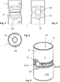
Fig. 2, 3 Längsschnitte durch ein Stabprofil zur Herstellung von zwei Gehäusen, zueinander um 90° versetzt; -
Figur 4 eine Draufsicht aufFig. 2 und -
Figur 5 eine räumliche Ansicht des Stabprofils. -
Figur 1 zeigt einen Rollenstößel 20 für eine Kraftstoffhochdruckpumpe einer Brennkraftmaschine. Der Rollenstößel 20 hat ein topfartiges Gehäuse 1 mit einem einteilig angebundenen Boden 3. In einer Außenseite 4 des Bodens 3 verläuft diametral durchgehend, somit seitlich offen, eine halbzylindrische Einformung 5 zur unmittelbaren Lagerung einer Rolle 6 für einen Hubnocken. Lateral ist der Rollenanlauf durch scheibenähnliche Elemente 17 begrenzt, welche radial nach außen durch einen Sprengring 18 fixiert sind. - Eine Innenseite 7 des Bodens 3 (s. a.
Fig. 2, 3 ) hat eine einteilig angebundene, domartig abgehobene Anlage 8 für einen Pumpenkolben innerhalb eines "hohlen" Innenraums 10. Beidseits der Einformung 5 ist durchgehend durch den Boden 3 je ein als Bohrung ausgebildeter Axialdurchtritt 19 für Kraftstoff, Schmiermittel oder Luft dargestellt. - Zum Verfahren zur Herstellung der Gehäuse 1 (s. insb.
Figuren 2 - 5 ):
Hierbei wird von einem Stabprofil 9 ausgegangen, welches in der Länge zweier fluchtend unmittelbar hintereinander angeordneter Gehäuse 1 vorliegt. Dieses "doppelte" Stabprofil 9 ist von einem Strang abgetrennt. Dabei werden die hohlzylindrischen Innenräume 10 mit den Anlagen 8 an Endstirnen 11 des Stabprofils 9 unter Beibehaltung eines axial mittigen Massivabschnitts 13 ausgedreht, was gleichzeitig erfolgt, oder, bei nur einem Werkzeug, nacheinander. Anschließend wird, wie gut dieFiguren 2, 5 zeigen, eine radial durchgehende Bohrung 14 durch den Massivabschnitt 13, zentriert auf einer Quermittelebene des Stabprofils 9, gebohrt und daraufhin durch Feinschleifen endbearbeitet. Schließlich wird das Stabprofil 9 entlang der Quermittelebene, an welcher sich zwei gespante Cracknuten 16 gegenüberliegen, gecrackt, so dass zwei fertige Gehäuse 1 zur Komplettierung mit der Rolle 6 vorliegen. -
- 1) Gehäuse
- 2) nicht vergeben
- 3) Boden
- 4) Außenseite
- 5) Einformung
- 6) Rolle
- 7) Innenseite
- 8) Anlage
- 9) Stabprofil
- 10) Innenraum
- 11) Endstirn
- 12)nicht vergeben
- 13)Massivabschnitt
- 14) Bohrung
- 15)Außenmantel
- 16)Cracknut
- 17)Element
- 18)Sprengring
- 19)Axialdurchtritt
- 20)Rollenstößel
Claims (7)
- Verfahren zur Herstellung von topfartigen Gehäusen (1) für Rollenstößel, wobei jedes Gehäuse (1) einen einteilig angebundenen Boden (3) hat, in dessen Außenseite (4) eine diametral durchlaufende halbzylindrische Einformung (5) zur unmittelbaren Lagerung einer Rolle (6) für einen periodischen Huberzeuger sitzt, wobei eine Innenseite (7) des Bodens (3) mit einer Anlage (8) für ein Stößelfolgeteil versehen ist, gekennzeichnet durch folgende Schritte:a) Bereithalten eines Stabprofils (9) als Halbzeug in der Länge zweier fluchtend unmittelbar hintereinander liegender Gehäuse (1);b) Einbringen von zwei im Wesentlichen hohlzylindrischen Innenräumen (10) mit den Anlagen (8) an Endstirnen (11) des Stabprofils (9) unter Beibehaltung eines axial mittigen Massivabschnitts (13) hierzwischen;c) Herstellen einer radial durchgehenden Bohrung (14) durch den Massivabschnitt (13), zentriert auf einer Quermittelebene des Stabprofils (9), undd) Trennen des Stabprofils (9) entlang der Quermittelebene unter Erzielung von zwei Gehäusen (1).
- Verfahren nach Anspruch 1, gekennzeichnet dadurch, dass als Trennvorgang im Schritt d) Cracken appliziert ist.
- Verfahren nach Anspruch 1, gekennzeichnet dadurch, dass die Innenräume (10) für die beiden Gehäuse (1) im Schritt c) durch einen spanabhebenden Prozess wie Drehen oder Fräsen realisiert sind.
- Verfahren nach Anspruch 1 oder 3, gekennzeichnet dadurch, dass die Anlagen (8) an den Böden (3) domartig abgehobende Ansätze sind.
- Verfahren nach Anspruch 1, gekennzeichnet dadurch, dass vor dem Trennen des Stabprofils im Schritt d) die erzielte Bohrung (14) durch Feinschleifen oder Honen endbearbeitet wird.
- Verfahren nach Anspruch 2, gekennzeichnet dadurch, dass in einen Außenmantel (15) des Stabprofils (9) zwei sich bogensehnenartig gegenüberliegende, parallel zur Axiallinie der Bohrung (14) verlaufende Cracknuten (16) gespant sind.
- Verfahren nach Anspruch 1, gekennzeichnet dadurch, dass auf die halbzylindrischen Einformungen (5) der Gehäuse (1) nach dem Trennen im Schritt d) eine Verschleißschutzschicht wie eine DLC-Hartstoffschicht aufgetragen wird.
Applications Claiming Priority (2)
| Application Number | Priority Date | Filing Date | Title |
|---|---|---|---|
| DE102017103481.1A DE102017103481B4 (de) | 2017-02-21 | 2017-02-21 | Verfahren zur Herstellung von Gehäusen für Rollenstößel |
| PCT/DE2018/100015 WO2018153395A1 (de) | 2017-02-21 | 2018-01-11 | VERFAHREN ZUR HERSTELLUNG VON GEHÄUSEN FÜR ROLLENSTÖßEL |
Publications (2)
| Publication Number | Publication Date |
|---|---|
| EP3586004A1 EP3586004A1 (de) | 2020-01-01 |
| EP3586004B1 true EP3586004B1 (de) | 2021-06-09 |
Family
ID=61189190
Family Applications (1)
| Application Number | Title | Priority Date | Filing Date |
|---|---|---|---|
| EP18704137.1A Active EP3586004B1 (de) | 2017-02-21 | 2018-01-11 | Verfahren zur herstellung von gehäusen für rollenstössel |
Country Status (4)
| Country | Link |
|---|---|
| EP (1) | EP3586004B1 (de) |
| CN (1) | CN110312866B (de) |
| DE (1) | DE102017103481B4 (de) |
| WO (1) | WO2018153395A1 (de) |
Family Cites Families (8)
| Publication number | Priority date | Publication date | Assignee | Title |
|---|---|---|---|---|
| CN101655020B (zh) * | 2009-09-21 | 2012-03-21 | 芜湖杰锋汽车动力系统有限公司 | 一种新型的机械式可变挺柱机构及其控制方法 |
| DE102009056304A1 (de) * | 2009-11-30 | 2011-06-01 | Schaeffler Technologies Gmbh & Co. Kg | Rollenstößel |
| DE102009056306A1 (de) * | 2009-11-30 | 2011-06-01 | Schaeffler Technologies Gmbh & Co. Kg | Rollenstößel |
| DE102009056303A1 (de) | 2009-11-30 | 2011-06-01 | Schaeffler Technologies Gmbh & Co. Kg | Rollenstößel |
| DE102010019982A1 (de) * | 2010-05-10 | 2011-11-10 | Schaeffler Technologies Gmbh & Co. Kg | Rollenstößel |
| DE102012207088B4 (de) * | 2012-04-27 | 2021-11-18 | Schaeffler Technologies AG & Co. KG | Rollenstößel für eine Kraftstoffhochdruckpumpe mit einer Ausdrehsiche-rung für ein teilringförmiges Schalensegment zur Lagerung der Rolle |
| EP3026232B1 (de) * | 2014-11-27 | 2020-01-08 | Aktiebolaget SKF | Mechanisches System zur Formung eines Kurvenrollers oder eines Kipphebels, Einspritzpumpe oder Ventilstellglied mit solch einem mechanischen System und Verfahren zur Herstellung solch eines mechanischen Systems |
| CN204457902U (zh) * | 2014-12-25 | 2015-07-08 | 潍柴动力股份有限公司 | 滚轮式挺柱 |
-
2017
- 2017-02-21 DE DE102017103481.1A patent/DE102017103481B4/de active Active
-
2018
- 2018-01-11 CN CN201880011879.6A patent/CN110312866B/zh active Active
- 2018-01-11 EP EP18704137.1A patent/EP3586004B1/de active Active
- 2018-01-11 WO PCT/DE2018/100015 patent/WO2018153395A1/de not_active Ceased
Non-Patent Citations (1)
| Title |
|---|
| None * |
Also Published As
| Publication number | Publication date |
|---|---|
| DE102017103481A1 (de) | 2018-08-23 |
| EP3586004A1 (de) | 2020-01-01 |
| DE102017103481B4 (de) | 2018-10-31 |
| CN110312866B (zh) | 2021-03-12 |
| WO2018153395A1 (de) | 2018-08-30 |
| CN110312866A (zh) | 2019-10-08 |
Similar Documents
| Publication | Publication Date | Title |
|---|---|---|
| DE102010022318B4 (de) | Rollenstößel | |
| DE102009056306A1 (de) | Rollenstößel | |
| WO2012119589A2 (de) | Verfahren zur herstellung eines kolbens für einen verbrennungsmotor | |
| DE112012003224B4 (de) | Kolben für einen Verbrennungsmotor und Verfahren dafür | |
| EP2386747B1 (de) | Rollenstößel | |
| DE102009056303A1 (de) | Rollenstößel | |
| DE102018103387A1 (de) | Pleuel für eine Brennkraftmaschine mit variabler Verdichtung | |
| WO2015074649A1 (de) | Vorrichtung zur veränderung des verdichtungsverhältnisses einer zylindereinheit einer hubkolbenbrennkraftmaschine | |
| DE10325914B4 (de) | Kolben für einen Verbrennungsmotor | |
| WO2006058525A1 (de) | Zweiteiliger kolben für einen verbrennungsmotor | |
| EP2634385B1 (de) | Verstellbare Nockenwelle | |
| WO2012013376A1 (de) | Tassenstössel und verfahren zu dessen herstellung | |
| EP3586004B1 (de) | Verfahren zur herstellung von gehäusen für rollenstössel | |
| DE102018120265A1 (de) | Stößel für eine Kraftstoffpumpe oder für einen Ventiltrieb | |
| EP3175107B1 (de) | Steckpumpe mit integrierter transportsicherung | |
| DE102019132604A1 (de) | Kurbelwellenanordnung mit schmierungsschema | |
| EP3298250B1 (de) | Brennkraftmaschine | |
| DE102014114785A1 (de) | Kolben für eine Brennkraftmaschine und dessen Herstellungsverfahren | |
| DE102013211279A1 (de) | Tassenstößel für den Ventiltrieb einer Brennkraftmaschine | |
| DE102014218872A1 (de) | Anordnung eines Kipphebels für den Ventiltrieb einer Brennkraftmaschine | |
| EP2923122B1 (de) | Kolben für einen verbrennungsmotor | |
| DE102017127044B4 (de) | Schiebenockenelement, Nockenwelle und Verfahren zur Herstellung eines Schiebenockenelements | |
| DE3049154A1 (de) | Ventilschaftfuehrung und verfahren zu ihrer herstellung | |
| EP3186492B1 (de) | Tassenstössel und verfahren zu dessen herstellung | |
| DE102013205111A1 (de) | Herstellungsverfahren für Schmiedekörper |
Legal Events
| Date | Code | Title | Description |
|---|---|---|---|
| STAA | Information on the status of an ep patent application or granted ep patent |
Free format text: STATUS: UNKNOWN |
|
| STAA | Information on the status of an ep patent application or granted ep patent |
Free format text: STATUS: THE INTERNATIONAL PUBLICATION HAS BEEN MADE |
|
| PUAI | Public reference made under article 153(3) epc to a published international application that has entered the european phase |
Free format text: ORIGINAL CODE: 0009012 |
|
| STAA | Information on the status of an ep patent application or granted ep patent |
Free format text: STATUS: REQUEST FOR EXAMINATION WAS MADE |
|
| 17P | Request for examination filed |
Effective date: 20190923 |
|
| AK | Designated contracting states |
Kind code of ref document: A1 Designated state(s): AL AT BE BG CH CY CZ DE DK EE ES FI FR GB GR HR HU IE IS IT LI LT LU LV MC MK MT NL NO PL PT RO RS SE SI SK SM TR |
|
| AX | Request for extension of the european patent |
Extension state: BA ME |
|
| DAV | Request for validation of the european patent (deleted) | ||
| DAX | Request for extension of the european patent (deleted) | ||
| REG | Reference to a national code |
Ref country code: DE Ref legal event code: R079 Ref document number: 502018005615 Country of ref document: DE Free format text: PREVIOUS MAIN CLASS: F04B0001040000 Ipc: F04B0001042600 |
|
| GRAP | Despatch of communication of intention to grant a patent |
Free format text: ORIGINAL CODE: EPIDOSNIGR1 |
|
| STAA | Information on the status of an ep patent application or granted ep patent |
Free format text: STATUS: GRANT OF PATENT IS INTENDED |
|
| RIC1 | Information provided on ipc code assigned before grant |
Ipc: F04B 1/0426 20200101AFI20200911BHEP Ipc: F04B 1/0439 20200101ALI20200911BHEP Ipc: F02M 59/10 20060101ALI20200911BHEP |
|
| INTG | Intention to grant announced |
Effective date: 20201013 |
|
| GRAS | Grant fee paid |
Free format text: ORIGINAL CODE: EPIDOSNIGR3 |
|
| GRAA | (expected) grant |
Free format text: ORIGINAL CODE: 0009210 |
|
| STAA | Information on the status of an ep patent application or granted ep patent |
Free format text: STATUS: THE PATENT HAS BEEN GRANTED |
|
| AK | Designated contracting states |
Kind code of ref document: B1 Designated state(s): AL AT BE BG CH CY CZ DE DK EE ES FI FR GB GR HR HU IE IS IT LI LT LU LV MC MK MT NL NO PL PT RO RS SE SI SK SM TR |
|
| REG | Reference to a national code |
Ref country code: GB Ref legal event code: FG4D Free format text: NOT ENGLISH |
|
| REG | Reference to a national code |
Ref country code: CH Ref legal event code: EP Ref country code: AT Ref legal event code: REF Ref document number: 1400725 Country of ref document: AT Kind code of ref document: T Effective date: 20210615 |
|
| REG | Reference to a national code |
Ref country code: DE Ref legal event code: R096 Ref document number: 502018005615 Country of ref document: DE |
|
| REG | Reference to a national code |
Ref country code: IE Ref legal event code: FG4D Free format text: LANGUAGE OF EP DOCUMENT: GERMAN |
|
| REG | Reference to a national code |
Ref country code: SE Ref legal event code: TRGR |
|
| REG | Reference to a national code |
Ref country code: LT Ref legal event code: MG9D |
|
| PG25 | Lapsed in a contracting state [announced via postgrant information from national office to epo] |
Ref country code: BG Free format text: LAPSE BECAUSE OF FAILURE TO SUBMIT A TRANSLATION OF THE DESCRIPTION OR TO PAY THE FEE WITHIN THE PRESCRIBED TIME-LIMIT Effective date: 20210909 Ref country code: LT Free format text: LAPSE BECAUSE OF FAILURE TO SUBMIT A TRANSLATION OF THE DESCRIPTION OR TO PAY THE FEE WITHIN THE PRESCRIBED TIME-LIMIT Effective date: 20210609 Ref country code: HR Free format text: LAPSE BECAUSE OF FAILURE TO SUBMIT A TRANSLATION OF THE DESCRIPTION OR TO PAY THE FEE WITHIN THE PRESCRIBED TIME-LIMIT Effective date: 20210609 Ref country code: FI Free format text: LAPSE BECAUSE OF FAILURE TO SUBMIT A TRANSLATION OF THE DESCRIPTION OR TO PAY THE FEE WITHIN THE PRESCRIBED TIME-LIMIT Effective date: 20210609 |
|
| REG | Reference to a national code |
Ref country code: NL Ref legal event code: MP Effective date: 20210609 |
|
| PG25 | Lapsed in a contracting state [announced via postgrant information from national office to epo] |
Ref country code: GR Free format text: LAPSE BECAUSE OF FAILURE TO SUBMIT A TRANSLATION OF THE DESCRIPTION OR TO PAY THE FEE WITHIN THE PRESCRIBED TIME-LIMIT Effective date: 20210910 Ref country code: NO Free format text: LAPSE BECAUSE OF FAILURE TO SUBMIT A TRANSLATION OF THE DESCRIPTION OR TO PAY THE FEE WITHIN THE PRESCRIBED TIME-LIMIT Effective date: 20210909 Ref country code: LV Free format text: LAPSE BECAUSE OF FAILURE TO SUBMIT A TRANSLATION OF THE DESCRIPTION OR TO PAY THE FEE WITHIN THE PRESCRIBED TIME-LIMIT Effective date: 20210609 Ref country code: RS Free format text: LAPSE BECAUSE OF FAILURE TO SUBMIT A TRANSLATION OF THE DESCRIPTION OR TO PAY THE FEE WITHIN THE PRESCRIBED TIME-LIMIT Effective date: 20210609 |
|
| PG25 | Lapsed in a contracting state [announced via postgrant information from national office to epo] |
Ref country code: ES Free format text: LAPSE BECAUSE OF FAILURE TO SUBMIT A TRANSLATION OF THE DESCRIPTION OR TO PAY THE FEE WITHIN THE PRESCRIBED TIME-LIMIT Effective date: 20210609 Ref country code: EE Free format text: LAPSE BECAUSE OF FAILURE TO SUBMIT A TRANSLATION OF THE DESCRIPTION OR TO PAY THE FEE WITHIN THE PRESCRIBED TIME-LIMIT Effective date: 20210609 Ref country code: SM Free format text: LAPSE BECAUSE OF FAILURE TO SUBMIT A TRANSLATION OF THE DESCRIPTION OR TO PAY THE FEE WITHIN THE PRESCRIBED TIME-LIMIT Effective date: 20210609 Ref country code: SK Free format text: LAPSE BECAUSE OF FAILURE TO SUBMIT A TRANSLATION OF THE DESCRIPTION OR TO PAY THE FEE WITHIN THE PRESCRIBED TIME-LIMIT Effective date: 20210609 Ref country code: CZ Free format text: LAPSE BECAUSE OF FAILURE TO SUBMIT A TRANSLATION OF THE DESCRIPTION OR TO PAY THE FEE WITHIN THE PRESCRIBED TIME-LIMIT Effective date: 20210609 Ref country code: RO Free format text: LAPSE BECAUSE OF FAILURE TO SUBMIT A TRANSLATION OF THE DESCRIPTION OR TO PAY THE FEE WITHIN THE PRESCRIBED TIME-LIMIT Effective date: 20210609 Ref country code: PT Free format text: LAPSE BECAUSE OF FAILURE TO SUBMIT A TRANSLATION OF THE DESCRIPTION OR TO PAY THE FEE WITHIN THE PRESCRIBED TIME-LIMIT Effective date: 20211011 Ref country code: NL Free format text: LAPSE BECAUSE OF FAILURE TO SUBMIT A TRANSLATION OF THE DESCRIPTION OR TO PAY THE FEE WITHIN THE PRESCRIBED TIME-LIMIT Effective date: 20210609 |
|
| PG25 | Lapsed in a contracting state [announced via postgrant information from national office to epo] |
Ref country code: PL Free format text: LAPSE BECAUSE OF FAILURE TO SUBMIT A TRANSLATION OF THE DESCRIPTION OR TO PAY THE FEE WITHIN THE PRESCRIBED TIME-LIMIT Effective date: 20210609 |
|
| REG | Reference to a national code |
Ref country code: DE Ref legal event code: R097 Ref document number: 502018005615 Country of ref document: DE |
|
| PLBE | No opposition filed within time limit |
Free format text: ORIGINAL CODE: 0009261 |
|
| STAA | Information on the status of an ep patent application or granted ep patent |
Free format text: STATUS: NO OPPOSITION FILED WITHIN TIME LIMIT |
|
| PG25 | Lapsed in a contracting state [announced via postgrant information from national office to epo] |
Ref country code: DK Free format text: LAPSE BECAUSE OF FAILURE TO SUBMIT A TRANSLATION OF THE DESCRIPTION OR TO PAY THE FEE WITHIN THE PRESCRIBED TIME-LIMIT Effective date: 20210609 |
|
| 26N | No opposition filed |
Effective date: 20220310 |
|
| PG25 | Lapsed in a contracting state [announced via postgrant information from national office to epo] |
Ref country code: AL Free format text: LAPSE BECAUSE OF FAILURE TO SUBMIT A TRANSLATION OF THE DESCRIPTION OR TO PAY THE FEE WITHIN THE PRESCRIBED TIME-LIMIT Effective date: 20210609 |
|
| PG25 | Lapsed in a contracting state [announced via postgrant information from national office to epo] |
Ref country code: IT Free format text: LAPSE BECAUSE OF FAILURE TO SUBMIT A TRANSLATION OF THE DESCRIPTION OR TO PAY THE FEE WITHIN THE PRESCRIBED TIME-LIMIT Effective date: 20210609 |
|
| REG | Reference to a national code |
Ref country code: DE Ref legal event code: R119 Ref document number: 502018005615 Country of ref document: DE |
|
| PG25 | Lapsed in a contracting state [announced via postgrant information from national office to epo] |
Ref country code: MC Free format text: LAPSE BECAUSE OF FAILURE TO SUBMIT A TRANSLATION OF THE DESCRIPTION OR TO PAY THE FEE WITHIN THE PRESCRIBED TIME-LIMIT Effective date: 20210609 |
|
| REG | Reference to a national code |
Ref country code: CH Ref legal event code: PL |
|
| GBPC | Gb: european patent ceased through non-payment of renewal fee |
Effective date: 20220111 |
|
| REG | Reference to a national code |
Ref country code: BE Ref legal event code: MM Effective date: 20220131 |
|
| PG25 | Lapsed in a contracting state [announced via postgrant information from national office to epo] |
Ref country code: LU Free format text: LAPSE BECAUSE OF NON-PAYMENT OF DUE FEES Effective date: 20220111 Ref country code: GB Free format text: LAPSE BECAUSE OF NON-PAYMENT OF DUE FEES Effective date: 20220111 Ref country code: DE Free format text: LAPSE BECAUSE OF NON-PAYMENT OF DUE FEES Effective date: 20220802 |
|
| PG25 | Lapsed in a contracting state [announced via postgrant information from national office to epo] |
Ref country code: BE Free format text: LAPSE BECAUSE OF NON-PAYMENT OF DUE FEES Effective date: 20220131 |
|
| PG25 | Lapsed in a contracting state [announced via postgrant information from national office to epo] |
Ref country code: LI Free format text: LAPSE BECAUSE OF NON-PAYMENT OF DUE FEES Effective date: 20220131 Ref country code: CH Free format text: LAPSE BECAUSE OF NON-PAYMENT OF DUE FEES Effective date: 20220131 |
|
| PG25 | Lapsed in a contracting state [announced via postgrant information from national office to epo] |
Ref country code: IE Free format text: LAPSE BECAUSE OF NON-PAYMENT OF DUE FEES Effective date: 20220111 |
|
| P01 | Opt-out of the competence of the unified patent court (upc) registered |
Effective date: 20230522 |
|
| REG | Reference to a national code |
Ref country code: AT Ref legal event code: MM01 Ref document number: 1400725 Country of ref document: AT Kind code of ref document: T Effective date: 20230111 |
|
| PG25 | Lapsed in a contracting state [announced via postgrant information from national office to epo] |
Ref country code: AT Free format text: LAPSE BECAUSE OF NON-PAYMENT OF DUE FEES Effective date: 20230111 |
|
| PG25 | Lapsed in a contracting state [announced via postgrant information from national office to epo] |
Ref country code: MK Free format text: LAPSE BECAUSE OF FAILURE TO SUBMIT A TRANSLATION OF THE DESCRIPTION OR TO PAY THE FEE WITHIN THE PRESCRIBED TIME-LIMIT Effective date: 20210609 Ref country code: CY Free format text: LAPSE BECAUSE OF FAILURE TO SUBMIT A TRANSLATION OF THE DESCRIPTION OR TO PAY THE FEE WITHIN THE PRESCRIBED TIME-LIMIT Effective date: 20210609 Ref country code: AT Free format text: LAPSE BECAUSE OF NON-PAYMENT OF DUE FEES Effective date: 20230111 |
|
| PG25 | Lapsed in a contracting state [announced via postgrant information from national office to epo] |
Ref country code: HU Free format text: LAPSE BECAUSE OF FAILURE TO SUBMIT A TRANSLATION OF THE DESCRIPTION OR TO PAY THE FEE WITHIN THE PRESCRIBED TIME-LIMIT; INVALID AB INITIO Effective date: 20180111 |
|
| PG25 | Lapsed in a contracting state [announced via postgrant information from national office to epo] |
Ref country code: MT Free format text: LAPSE BECAUSE OF FAILURE TO SUBMIT A TRANSLATION OF THE DESCRIPTION OR TO PAY THE FEE WITHIN THE PRESCRIBED TIME-LIMIT Effective date: 20210609 |
|
| PG25 | Lapsed in a contracting state [announced via postgrant information from national office to epo] |
Ref country code: TR Free format text: LAPSE BECAUSE OF FAILURE TO SUBMIT A TRANSLATION OF THE DESCRIPTION OR TO PAY THE FEE WITHIN THE PRESCRIBED TIME-LIMIT Effective date: 20210609 |
|
| PGFP | Annual fee paid to national office [announced via postgrant information from national office to epo] |
Ref country code: SE Payment date: 20260121 Year of fee payment: 9 |
|
| PGFP | Annual fee paid to national office [announced via postgrant information from national office to epo] |
Ref country code: AT Payment date: 20260410 Year of fee payment: 5 |
|
| PGFP | Annual fee paid to national office [announced via postgrant information from national office to epo] |
Ref country code: FR Payment date: 20260123 Year of fee payment: 9 |