EP3585991B1 - Verfahren zum betrieb einer hubkolbenmaschine mit wenigstens einer hydraulisch längenverstellbaren pleuelstange - Google Patents
Verfahren zum betrieb einer hubkolbenmaschine mit wenigstens einer hydraulisch längenverstellbaren pleuelstange Download PDFInfo
- Publication number
- EP3585991B1 EP3585991B1 EP18708624.4A EP18708624A EP3585991B1 EP 3585991 B1 EP3585991 B1 EP 3585991B1 EP 18708624 A EP18708624 A EP 18708624A EP 3585991 B1 EP3585991 B1 EP 3585991B1
- Authority
- EP
- European Patent Office
- Prior art keywords
- length
- piston
- piston rod
- compression ratio
- connecting rod
- Prior art date
- Legal status (The legal status is an assumption and is not a legal conclusion. Google has not performed a legal analysis and makes no representation as to the accuracy of the status listed.)
- Active
Links
Images

Classifications
-
- F—MECHANICAL ENGINEERING; LIGHTING; HEATING; WEAPONS; BLASTING
- F02—COMBUSTION ENGINES; HOT-GAS OR COMBUSTION-PRODUCT ENGINE PLANTS
- F02B—INTERNAL-COMBUSTION PISTON ENGINES; COMBUSTION ENGINES IN GENERAL
- F02B75/00—Other engines
- F02B75/04—Engines with variable distances between pistons at top dead-centre positions and cylinder heads
- F02B75/044—Engines with variable distances between pistons at top dead-centre positions and cylinder heads by means of an adjustable piston length
-
- F—MECHANICAL ENGINEERING; LIGHTING; HEATING; WEAPONS; BLASTING
- F02—COMBUSTION ENGINES; HOT-GAS OR COMBUSTION-PRODUCT ENGINE PLANTS
- F02B—INTERNAL-COMBUSTION PISTON ENGINES; COMBUSTION ENGINES IN GENERAL
- F02B75/00—Other engines
- F02B75/04—Engines with variable distances between pistons at top dead-centre positions and cylinder heads
- F02B75/045—Engines with variable distances between pistons at top dead-centre positions and cylinder heads by means of a variable connecting rod length
-
- F—MECHANICAL ENGINEERING; LIGHTING; HEATING; WEAPONS; BLASTING
- F01—MACHINES OR ENGINES IN GENERAL; ENGINE PLANTS IN GENERAL; STEAM ENGINES
- F01M—LUBRICATING OF MACHINES OR ENGINES IN GENERAL; LUBRICATING INTERNAL COMBUSTION ENGINES; CRANKCASE VENTILATING
- F01M1/00—Pressure lubrication
- F01M1/08—Lubricating systems characterised by the provision therein of lubricant jetting means
-
- F—MECHANICAL ENGINEERING; LIGHTING; HEATING; WEAPONS; BLASTING
- F01—MACHINES OR ENGINES IN GENERAL; ENGINE PLANTS IN GENERAL; STEAM ENGINES
- F01P—COOLING OF MACHINES OR ENGINES IN GENERAL; COOLING OF INTERNAL-COMBUSTION ENGINES
- F01P3/00—Liquid cooling
- F01P3/06—Arrangements for cooling pistons
- F01P3/08—Cooling of piston exterior only, e.g. by jets
-
- F—MECHANICAL ENGINEERING; LIGHTING; HEATING; WEAPONS; BLASTING
- F02—COMBUSTION ENGINES; HOT-GAS OR COMBUSTION-PRODUCT ENGINE PLANTS
- F02D—CONTROLLING COMBUSTION ENGINES
- F02D15/00—Varying compression ratio
- F02D15/02—Varying compression ratio by alteration or displacement of piston stroke
-
- F—MECHANICAL ENGINEERING; LIGHTING; HEATING; WEAPONS; BLASTING
- F15—FLUID-PRESSURE ACTUATORS; HYDRAULICS OR PNEUMATICS IN GENERAL
- F15B—SYSTEMS ACTING BY MEANS OF FLUIDS IN GENERAL; FLUID-PRESSURE ACTUATORS, e.g. SERVOMOTORS; DETAILS OF FLUID-PRESSURE SYSTEMS, NOT OTHERWISE PROVIDED FOR
- F15B11/00—Servomotor systems without provision for follow-up action; Circuits therefor
- F15B11/16—Servomotor systems without provision for follow-up action; Circuits therefor with two or more servomotors
-
- F—MECHANICAL ENGINEERING; LIGHTING; HEATING; WEAPONS; BLASTING
- F15—FLUID-PRESSURE ACTUATORS; HYDRAULICS OR PNEUMATICS IN GENERAL
- F15B—SYSTEMS ACTING BY MEANS OF FLUIDS IN GENERAL; FLUID-PRESSURE ACTUATORS, e.g. SERVOMOTORS; DETAILS OF FLUID-PRESSURE SYSTEMS, NOT OTHERWISE PROVIDED FOR
- F15B21/00—Common features of fluid actuator systems; Fluid-pressure actuator systems or details thereof, not covered by any other group of this subclass
- F15B21/04—Special measures taken in connection with the properties of the fluid
-
- F—MECHANICAL ENGINEERING; LIGHTING; HEATING; WEAPONS; BLASTING
- F15—FLUID-PRESSURE ACTUATORS; HYDRAULICS OR PNEUMATICS IN GENERAL
- F15B—SYSTEMS ACTING BY MEANS OF FLUIDS IN GENERAL; FLUID-PRESSURE ACTUATORS, e.g. SERVOMOTORS; DETAILS OF FLUID-PRESSURE SYSTEMS, NOT OTHERWISE PROVIDED FOR
- F15B21/00—Common features of fluid actuator systems; Fluid-pressure actuator systems or details thereof, not covered by any other group of this subclass
- F15B21/04—Special measures taken in connection with the properties of the fluid
- F15B21/041—Removal or measurement of solid or liquid contamination, e.g. filtering
-
- F—MECHANICAL ENGINEERING; LIGHTING; HEATING; WEAPONS; BLASTING
- F16—ENGINEERING ELEMENTS AND UNITS; GENERAL MEASURES FOR PRODUCING AND MAINTAINING EFFECTIVE FUNCTIONING OF MACHINES OR INSTALLATIONS; THERMAL INSULATION IN GENERAL
- F16C—SHAFTS; FLEXIBLE SHAFTS; ELEMENTS OR CRANKSHAFT MECHANISMS; ROTARY BODIES OTHER THAN GEARING ELEMENTS; BEARINGS
- F16C7/00—Connecting-rods or like links pivoted at both ends; Construction of connecting-rod heads
- F16C7/06—Adjustable connecting-rods
-
- F—MECHANICAL ENGINEERING; LIGHTING; HEATING; WEAPONS; BLASTING
- F16—ENGINEERING ELEMENTS AND UNITS; GENERAL MEASURES FOR PRODUCING AND MAINTAINING EFFECTIVE FUNCTIONING OF MACHINES OR INSTALLATIONS; THERMAL INSULATION IN GENERAL
- F16J—PISTONS; CYLINDERS; SEALINGS
- F16J7/00—Piston-rods
-
- F—MECHANICAL ENGINEERING; LIGHTING; HEATING; WEAPONS; BLASTING
- F02—COMBUSTION ENGINES; HOT-GAS OR COMBUSTION-PRODUCT ENGINE PLANTS
- F02D—CONTROLLING COMBUSTION ENGINES
- F02D2700/00—Mechanical control of speed or power of a single cylinder piston engine
- F02D2700/03—Controlling by changing the compression ratio
Definitions
- the invention relates to a reciprocating piston machine, in particular an internal combustion engine, with at least one hydraulically steerable connecting rod for setting a compression ratio ⁇ , the connecting rod having a piston and a hydraulic cylinder for length adjustment, the piston with the hydraulic cylinder delimiting at least one working space, at least two by its filling level Switching positions of the connecting rod are possible.
- the invention also relates to a method for operating such a reciprocating piston machine.
- a full load with a low compression ratio ⁇ and a partial load and starting the reciprocating engine with an increased compression ratio ⁇ can be operated in the drive mode. This reduces consumption in the partial load range, increases the compression pressure with an increased compression ratio ⁇ at start and reduces the peak pressure with a reduced compression ratio ⁇ at high power and prevents knocking.
- the pamphlet WO 2015/055582 A2 relates to a length-adjustable connecting rod for a reciprocating piston engine with a variable compression ratio, the connecting rod having at least a first rod part with a small connecting rod eye and a second rod part with a large connecting rod eye, which two rod parts can be moved telescopically towards and / or into one another, the second rod part being a guide cylinder and the first rod part form a piston element that is longitudinally displaceable in the guide cylinder, with a first high-pressure chamber being spanned between the second rod part and the piston element on the side of the piston element facing the large connecting rod eye, into which at least one first oil channel opens, in which in particular one in the direction of the first
- the first check valve opening the high pressure chamber is arranged, with at least a first of the first high pressure chamber Return channel goes out, the outflow cross-section of which can be closed by a control valve in a first position and released in a second position, the control valve preferably having an actuating
- a VCR piston machine with a connecting rod which has a compression piston
- the connecting rod having an adjusting mechanism for adjusting the compression piston
- the adjusting mechanism having a first support piston in a first support cylinder and a second support piston in a second support cylinder of the connecting rod
- the first and the second support cylinders are each connected to a first control line, via which a medium flows in and out of the respective support cylinder for adjusting the respective support cylinder, with at least one further, second control line for at least one outflow of the medium for adjusting the associated Support cylinder opens.
- the connecting rod length is varied between at least one long and one short switching position as a function of the characteristic diagram, the first long switching position causing a high compression ratio and the second, short switching position causing a low compression ratio ⁇ .
- the length of the connecting rod remains unchanged. Only when the compression ratio ⁇ is to be set to a different value, for example when changing from the full load range to a part-load range, the compression ratio ⁇ and thus the length of the connecting rod is also changed.
- a first aspect of the invention relates to a method for operating a reciprocating piston engine, in particular an internal combustion engine, with at least one hydraulically adjustable connecting rod for setting a compression ratio ⁇ , the connecting rod having a piston and a hydraulic cylinder for adjusting the length, the piston with the hydraulic cylinder at least one working space limited, by the level of which at least two switching positions of the connecting rod are possible, regardless of the setting of the compression ratio ⁇ an at least partial filling and emptying of the working space is carried out depending on at least one first predetermined condition in order to at least partially exchange a hydraulic medium in the at least one To effect work space.
- a second aspect of the invention relates to a reciprocating piston engine, in particular an internal combustion engine, with at least one hydraulically adjustable connecting rod for adjusting the compression ratio ⁇ , the connecting rod having a piston with a hydraulic cylinder for adjusting the length, the piston with the hydraulic cylinder at least one Working space limited, the filling level of which enables at least two switching positions of the connecting rod, the reciprocating piston machine also having means for performing, depending on at least one first predetermined condition and independently of the setting of the compression ratio ⁇ , at least partial filling and emptying of the at least one working space in order to effect an at least partial exchange of a hydraulic medium in the at least one working space.
- the invention is based in particular on the knowledge that high loads act on the relatively small volume of the hydraulic cylinder due to the piston, which is exposed to the pressures in the working chamber of the internal combustion engine. These lead to an increase in the temperature of the hydraulic medium in the working spaces (pressure chambers of the hydraulic cylinders).
- aging effects of the hydraulic medium in particular due to overheating, can occur.
- additives in the hydraulic medium can be chemically decomposed or destroyed. This effect is further enhanced by the fact that in an internal combustion engine, waste heat from the combustion process acts on the hydraulic cylinder through radiation and heat conduction.
- the invention pursues the approach of bringing about an exchange of the hydraulic medium by filling and emptying, although no change in the compression ratio ⁇ should be set.
- the compression ratio ⁇ preferably has essentially the same value before and after filling and emptying.
- At least one work area can be completely filled and emptied. However, only partial filling and emptying are preferably carried out, so that only part of the hydraulic medium is exchanged.
- the piston with the hydraulic cylinder delimits two working spaces, the respective filling level of which enables the at least two switching positions of the connecting rod, the working spaces being filled and emptied in opposite directions.
- the at least partial filling and emptying of the at least one working space is carried out at a low load point, in particular below half the maximum load and / or in the low torque, in particular below half the maximum torque.
- Filling and emptying at a relatively low load point ensures that the connecting rod in the long switching position, which is at least passed through during filling and emptying, is not exposed to excessive loads that could damage the length-adjustable connecting rod.
- the long switching state for setting a high compression ratio ⁇ is generally in the lower part-load range.
- an injection quantity of a fuel and / or the lambda ratio of a cylinder of the internal combustion engine, which has the at least one hydraulically adjustable connecting rod is temporarily adjusted in order to reduce a load on the cylinder, in particular when there is a short switch position.
- a load on the cylinder in particular when there is a short switch position.
- the at least one is hydraulically adjustable in length Sprayed connecting rod for cooling with cooling medium, in particular with hydraulic medium, and / or a lubricating medium.
- This spraying is preferably carried out by a piston cooling device which additionally wets the at least one hydraulically adjustable connecting rod.
- the spraying of the connecting rod is initiated as a function of at least one second predetermined condition, in particular before the at least partial filling and emptying of a working space is carried out.
- filling and emptying of the working space for at least partial replacement of the hydraulic medium is only carried out when cooling by means of spraying with the cooling medium is no longer sufficient.
- the at least one first and / or second predetermined condition relates to a parameter which is selected from a group which has the following parameters: temperature of the hydraulic medium, time since changing the compression ratio ⁇ , time since a last, at least partial exchange of the hydraulic medium, quantity of the hydraulic medium exchanged in a last, at least partial exchange of the hydraulic medium, switching position, load point.
- filling and emptying take place in a reciprocating piston machine with a plurality of hydraulically adjustable connecting rods in relation to the connecting rods one after the other. This can prevent a noticeable change in drivability due to filling and emptying a vehicle with a reciprocating piston engine according to the invention can be perceived.
- the piston cooling device is set up in such a way that the connecting rod is also sprayed with a cooling medium, in particular a hydraulic medium and / or a lubricating medium.
- the piston cooling device has at least one spray nozzle which is directed at at least a section of a movement area of the connecting rod.
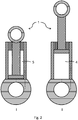
- Fig. 1 shows an embodiment of a length-adjustable connecting rod 1, as it can be used in a reciprocating piston engine 10 according to the invention.
- the connecting rod preferably has a small connecting rod eye 6 and a large connecting rod eye 7.
- the small connecting rod eye 6 is connected to a piston 2 via a shaft.
- the large connecting rod eye 7 is connected to a hydraulic cylinder 3 in which the piston 2 is movably arranged.
- the piston 2 preferably divides the hydraulic cylinder 3 into two working spaces 4, 5.
- the second working space 5 is preferably closed to the outside by a sleeve 8.
- the first working space 4 is preferably filled and emptied with hydraulic medium via a line 9b, in particular a hydraulic line, which preferably leads into the large connecting rod eye.
- the second working space 5 is preferably filled and emptied via a further line 9a. This further line 9a also preferably leads into the large connecting rod eye.
- the supply of the lines 9a, 9b with hydraulic medium takes place preferably via a crankshaft, not shown, of the reciprocating piston engine.
- a change in the position of the piston 2 in the hydraulic cylinder 3 can be implemented, for example, via different pressures of the hydraulic medium applied to the lines 9a, 9b.
- a switching device for switching the inflow and / or outflow from the working spaces 4, 5 is provided in the connecting rod 1. This switching element can also be actuated by means of various pressures which are provided by the hydraulic medium and / or electromagnetically and / or mechanically.
- a length-adjustable connecting rod 1 within the meaning of the invention is not limited to the embodiment in FIG Fig. 1 limited.
- the piston can also be a so-called rotary piston, which prevents or enables length adjustment of the connecting rod by means of a lock and / or a threaded spindle.
- the piston can in Interaction with the hydraulic cylinder can also be set up to change the position of an eccentrically arranged small connecting rod eye 6, so that an effective connecting rod length, i.e. the distance between the center of the large connecting rod eye 7 and the center of the small connecting rod eye 6, can be changed.
- Fig. 2 shows two switching positions of a length-adjustable connecting rod Fig. 1 .
- the first, short switching position the first working space 4 is completely emptied and / or the second working space 5 is completely filled.
- the second, long switch position II the first working space 4 is completely filled and / or the second working space 5 is completely emptied.
- the at least two switching positions I, II of the connecting rod 1 thus correspond to different length states of the length-adjustable connecting rod 1.
- the length-adjustable connecting rod 1 is transferred from the switching state I to the second switching state II and back to the first switching state I.
- the connecting rod 1 is transferred from the second switching state II to the first switching state I and back into the second switching state II.
- the working spaces 4, 5 are each completely emptied and filled, more preferably they are only partially emptied and filled. More preferably, only one of the working spaces 4, 5 is at least partially filled and emptied.
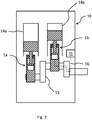
- Fig. 3 shows a first embodiment of a reciprocating piston engine 10 according to the invention.
- This has two cylinders 14a, 14b, each of which has a length-adjustable connecting rod 1a and 1b, which together with a reciprocating piston each delimit a combustion chamber in the cylinder.
- the length-adjustable connecting rods 1a, 1b each connect the reciprocating pistons of the cylinders 14a, 14b to the crankshaft 15.
- the reciprocating piston engine 10 also has a controller 11 which controls filling and emptying of at least one of the working spaces 4, 5 of the length-adjustable connecting rods 1a, 1b via a line 16, which is preferably passed through the crankshaft 15.
- the respective work rooms 4, 5 of the Length-adjustable connecting rods 1a, 1b can be supplied with a common hydraulic line 16 or with separate hydraulic lines.
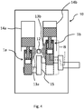
- FIG. 4 shows a second exemplary embodiment of a reciprocating piston engine 10 according to the invention.
- the second exemplary embodiment has a cooling device 12 which can spray the length-adjustable connecting rod 1a, 1b of the cylinders 14a, 14b with a cooling medium, in particular hydraulic medium.
- the cooling device 12 which is preferably integrated into a piston cooling device, preferably has spray nozzles which generate spray cones 13a, 13b which spray the length-adjustable connecting rods 1a, 1b in at least a section of their range of movement B.
- the range of motion of the second length-adjustable connecting rod 1b is indicated by dashed lines and its axial extent with respect to the second cylinder 14b with a curly bracket.
- a reciprocating piston machine according to the invention can additionally have means 11 for carrying out an at least partial filling and emptying 11. This alternative would correspond to the one from Fig. 3 with the cooling device 12 Fig. 4 .
Landscapes
- Engineering & Computer Science (AREA)
- General Engineering & Computer Science (AREA)
- Mechanical Engineering (AREA)
- Chemical & Material Sciences (AREA)
- Combustion & Propulsion (AREA)
- Physics & Mathematics (AREA)
- Fluid Mechanics (AREA)
- Analytical Chemistry (AREA)
- Shafts, Cranks, Connecting Bars, And Related Bearings (AREA)
- Output Control And Ontrol Of Special Type Engine (AREA)
- Lubrication Of Internal Combustion Engines (AREA)
Description
- Die Erfindung betrifft eine Hubkolbenmaschine, insbesondere eine Brennkraftmaschine, mit wenigstens einer hydraulisch lenkverstellbaren Pleuelstange zum Einstellen eines Verdichtungsverhältnisses ε, wobei die Pleuelstange einen Kolben und einen Hydraulikzylinder zur Längenverstellung aufweist, wobei der Kolben mit dem Hydraulikzylinder wenigstens einen Arbeitsraum begrenzt, durch dessen Füllstand wenigstens zwei Schaltstellungen der Pleuelstange möglich sind. Des Weiteren betrifft die Erfindung ein Verfahren zum Betrieb einer solchen Hubkolbenmaschine.
- Durch Ändern des Verdichtungsverhältnisses einer Hubkolbenmaschine kann im Antriebsmodus eine Volllast mit geringem Verdichtungsverhältnis ε und eine Teillast und das Starten der Hubkolbenmaschine mit einem erhöhten Verdichtungsverhältnis ε betrieben werden. Dadurch wird im Teillastbereich der Verbrauch verringert, beim Start der Kompressionsdruck mit erhöhtem Verdichtungsverhältnis ε gesteigert und bei hoher Leistung der Spitzendruck mit verringertem Verdichtungsverhältnis ε reduziert sowie Klopfen verhindert.
- Die Druckschrift
WO 2015/055582 A2 betrifft eine längenverstellbare Pleuelstange für eine Hubkolbenmaschine mit veränderbarem Verdichtungsverhältnis, wobei die Pleuelstange zumindest einen ersten Stangenteil mit einem kleinen Pleuelauge und einen zweiten Stangenteil mit einem großen Pleuelauge, welche beiden Stangenteile teleskopartig zu- und/oder ineinander verschiebbar sind, wobei der zweite Stangenteil einen Führungszylinder und der erste Stangenteil ein im Führungszylinder längsverschiebbares Kolbenelement ausbilden, wobei auf der dem großen Pleuelauge zugewandten Seite des Kolbenelements zwischen dem zweiten Stangenteil und dem Kolbenelement ein erster Hochdruckraum aufgespannt ist, in den zumindest ein erster Ölkanal einmündet, in welchem insbesondere ein in Richtung des ersten Hochdruckraumes öffnendes erstes Rückschlagventil angeordnet ist, wobei vom ersten Hochdruckraum zumindest ein erster Rücklaufkanal ausgeht, dessen Abflussquerschnitt durch ein Steuerventil in einer ersten Stellung verschließbar und in einer zweiten Stellung freigebbar ist, wobei vorzugsweise das Steuerventil einen in einer Aufnahmebohrung des zweiten Stangenteils der Pleuelstange axial verschiebbaren Stellkolben aufweist, welcher insbesondere durch eine Rückstellfeder in die erste Stellung und durch eine Betätigungskraft entgegen der Kraft der Rückstellfeder in die zweite Stellung verschiebbar ist, wobei das Kolbenelement als zweiseitig wirkender Kolben, vorzugsweise als Stufenkolben, ausgebildet ist. - Auch ist bekannt, statt einem teleskopartigen System zur Verstellung des Verdichtungsverhältnisses ε ein exzentrisch angeordnetes kleines Pleuelauge, einen exzentrischen Kolbenbolzen oder einen exzentrischen Hubzapfen der Kurbelwelle einzusetzen.
- So betrifft die Druckschrift
DE 10 2014 004 987 A1 eine VCR-Kolbenmaschine mit einem Pleuel, welches einen Verdichtungskolben aufweist, wobei das Pleuel einen Verstellmechanismus zur Verstellung des Verdichtungskolbens aufweist und der Verstellmechanismus einen ersten Stützkolben in einem ersten Stützzylinder und einen zweiten Stützkolben in einem zweiten Stützzylinder des Pleuels aufweist, wobei der erste und der zweite Stützzylinder jeweils mit einer ersten Steuerleitung verbunden sind, über die ein Medium in den jeweiligen Stützzylinder ein- und ausfließt zum Verstellen des jeweiligen Stützzylinders, wobei in zumindest einen der beiden Stützzylinder zumindest eine weitere, zweite Steuerleitung zum zumindest Abfließen des Medium zum Verstellen des zugeordneten Stützzylinders mündet. - Im Allgemeinen wird die Pleuellänge kennfeldabhängig zwischen wenigstens einer langen und einer kurzen Schaltstellung variiert, wobei die erste lange Schaltstellung ein hohes Verdichtungsverhältnis und die zweite, kurze Schaltstellung ein geringes Verdichtungsverhältnis ε bewirkt. Je nach Fahrmodus und der dadurch angeforderten Last bleibt die Länge des Pleuels unverändert. Erst wenn das Verdichtungsverhältnis ε auf einen anderen Wert eingestellt werden soll, zum Beispiel beim Wechseln vom Volllast-Bereich in einen Teillast-Bereich, wird auch das Verdichtungsverhältnis ε und damit die Länge der Pleuelstange verändert.
- Es ist eine Aufgabe der Erfindung, eine Hubkolbenmaschine und ein Verfahren zum Betrieb einer solchen Hubkolbenmaschine bereitzustellen, welche die Funktion wenigstens einer hydraulisch längenverstellbaren Pleuelstange der Hubkolbenmaschine gewährleistet. Insbesondere ist es eine Aufgabe der Erfindung, ein Überhitzen eines Hydraulikmediums, welches zur Längenverstellung der hydraulisch längenverstellbaren Pleuelstange eingesetzt wird, zu verhindern. Dies ist in
US 2009/0205615 A1 dadurch gelöst, dass das Hydraulikmedium bei jeder Kurbelwellenumdrehung ausgetauscht wird. - Diese Aufgabe wird durch ein Verfahren nach Anspruch 1 und eine Hubkolbenmaschine nach Anspruch 12 gelöst. Vorteilhafte Ausgestaltungen werden in den abhängigen Ansprüchen beansprucht. Die Ansprüche werden ausdrücklich zum Bestandteil der Beschreibung gemacht.
- Ein erster Aspekt der Erfindung betrifft ein Verfahren zum Betrieb einer Hubkolbenmaschine, insbesondere einer Brennkraftmaschine, mit wenigstens einer hydraulisch längenverstellbaren Pleuelstange zum Einstellen eines Verdichtungsverhältnisses ε, wobei die Pleuelstange einen Kolben und einen Hydraulikzylinder zur Längenverstellung aufweist, wobei der Kolben mit dem Hydraulikzylinder wenigstens einen Arbeitsraum begrenzt, durch dessen Füllstand wenigstens zwei Schaltstellungen der Pleuelstange möglich sind, wobei unabhängig vom Einstellen des Verdichtungsverhältnisses ε ein wenigstens teilweises Befüllen und Entleeren des Arbeitsraums in Abhängigkeit von wenigstens einer ersten vorbestimmten Bedingung durchgeführt wird, um einen wenigstens teilweisen Austausch eines Hydraulikmediums in dem wenigstens einen Arbeitsraum zu bewirken.
- Ein zweiter Aspekt der Erfindung betrifft eine Hubkolbenmaschine, insbesondere Brennkraftmaschine, mit wenigstens einer hydraulisch längenverstellbaren Pleuelstange zum Einstellen des Verdichtungsverhältnisses ε, wobei die Pleuelstange einen Kolben mit einem Hydraulikzylinder zur Längenverstellung aufweist, wobei der Kolben mit dem Hydraulikzylinder wenigstens einen Arbeitsraum begrenzt, durch dessen Füllstand wenigstens zwei Schaltstellungen der Pleuelstange möglich sind, wobei die Hubkolbenmaschine des Weiteren Mittel zum Durchführen, in Abhängigkeit von wenigstens einer ersten vorbestimmten Bedingung und unabhängig vom Einstellen des Verdichtungsverhältnisses ε, eines wenigstens teilweisen Befüllens und Entleerens des wenigstens einen Arbeitsraums aufweist, um einen wenigstens teilweisen Austausch eines Hydraulikmediums in dem wenigstens einen Arbeitsraum zu bewirken.
- Die Erfindung beruht insbesondere auf der Erkenntnis, dass auf dem relativ kleinen Volumen des Hydraulikzylinders durch den Kolben, welcher den Drücken im Arbeitsraum der Brennkraftmaschine ausgesetzt ist, hohe Belastungen einwirken. Diese führen zu einem Anstieg der Temperatur des Hydraulikmediums in den Arbeitsräumen (Druckkammern der Hydraulikzylinder). Insbesondere wenn das Hydraulikmedium für längere Zeit in dem Hydraulikzylinder verweilt, kann es dabei zu Alterungseffekten des Hydraulikmediums, insbesondere durch Überhitzen, kommen. Dabei können insbesondere Additive in dem Hydraulikmedium chemisch zersetzt bzw. zerstört werden. Dieser Effekt wird noch dadurch begünstigt, da bei einer Brennkraftmaschine Abwärme aus dem Verbrennungsprozess durch Strahlung und Wärmeleitung auf den Hydraulikzylinder wirkt.
- Die Erfindung verfolgt den Ansatz, durch ein Befüllen und Entleeren einen Austausch des Hydraulikmediums herbeizuführen, obwohl keine Veränderung des Verdichtungsverhältnisses ε eingestellt werden soll. Vorzugsweise weist das Verdichtungsverhältnis ε dabei vor und nach dem Befüllen und Entleeren im Wesentlichen den gleichen Wert auf.
- Durch den Austausch des Hydraulikmediums können Alterungseffekte verhindert werden. Insbesondere kann ein Verstopfen der Leitungen des Hydraulikmediums in der längenverstellbaren Pleuelstange oder in der Kurbelwelle verhindert werden oder zumindest die Wahrscheinlichkeit eines solchen Vorfalls verringert werden.
- Wenigstens eine Arbeitsraum kann hierbei vollständig befüllt und entleert werden. Vorzugsweise wird jedoch nur ein teilweises Befüllen und Entleeren ausgeführt, so dass nur ein Teil des Hydraulikmediums ausgetauscht wird.
- In einer vorteilhaften Ausgestaltung der Erfindung begrenzt der Kolben mit dem Hydraulikzylinder zwei Arbeitsräume, durch deren jeweiligen Füllstand die wenigstens zwei Schaltstellungen der Pleuelstange möglich sind, wobei die Arbeitsräume jeweils gegenläufig gefüllt und entleert werden.
- Erfindungsgemäss wird das wenigstens teilweise Befüllen und Entleeren des wenigstens einen Arbeitsraums bei einem niedrigen Lastpunkt, insbesondere unterhalb der halben maximalen Last und/oder im niedrigen Drehmoment, insbesondere unterhalb des halben maximalen Drehmoments, durchgeführt. Durch das Befüllen und Entleeren bei einem relativ niedrigen Lastpunkt wird gewährleistet, dass die Pleuelstange in der langen Schaltstellung, welche beim Befüllen und Entleeren wenigstens durchlaufen wird, nicht zu großen Belastungen ausgesetzt wird, welche zu Schäden an der längenverstellbaren Pleuelstange führen könnten. Wie eingangs erwähnt, liegt der lange Schaltzustand zum Einstellen eines hohen Verdichtungsverhältnisses ε im Allgemeinen im unteren Teillast-Bereich vor.
- In einer weiteren vorteilhaften Ausgestaltung des erfindungsgemäßen Verfahrens wird eine Einspritzmenge eines Brennstoffs und/oder das Lambda-Verhältnis eines Zylinders der Brennkraftmaschine, welche die wenigstens eine hydraulisch längenverstellbare Pleuelstange aufweist, vorübergehend angepasst, um eine Last in Bezug auf den Zylinder zu verringern, insbesondere wenn eine kurze Schaltstellung vorliegt. Insbesondere bei einem Befüllen und Entleeren des Arbeitsraums, ausgehend von einer kurzen Schaltstellung, bei der, wie eingangs erläutert, im Allgemeinen eine hohe Last vorliegt, ist es vorteilhaft, die Last zu verringern. Hierdurch kann eine etwaige Beschädigung der längenverstellbaren Pleuelstange vermieden werden.
- In einer weiteren vorteilhaften Ausgestaltung des erfindungsgemäßen Verfahrens wird die wenigstens eine hydraulisch längenverstellbare Pleuelstange zur Kühlung mit Kühlmedium, insbesondere mit Hydraulikmedium, und/oder einem Schmiermedium besprüht. Vorzugsweise wird dieses Besprühen durch eine Kolbenkühlungseinrichtung ausgeführt, welche zusätzlich die wenigstens eine hydraulisch längenverstellbare Pleuelstange benetzt. Hierdurch kann unabhängig oder zusätzlich zu einem Austausch des Hydraulikmediums ein Alterungseffekt des Hydraulikmediums verhindert werden, indem die Pleuelstange von außen gekühlt wird.
- In einer weiteren vorteilhaften Ausgestaltung der Erfindung wird das Besprühen der Pleuelstange in Abhängigkeit von wenigstens einer zweiten vorbestimmten Bedingung eingeleitet, insbesondere bevor das wenigstens teilweise Befüllen und Entleeren eines Arbeitsraums durchgeführt wird. Gemäß dieser vorteilhaften Ausgestaltung wird ein Befüllen und Entleeren des Arbeitsraums zum wenigstens teilweisen Austausch des Hydraulikmediums erst dann ausgeführt, wenn eine Kühlung mittels des Besprühens mit dem Kühlmedium nicht mehr ausreicht. Hierdurch kann eine zeitweise Abweichung von der optimalen Pleuellänge verhindert oder wenigstens auf eine minimale Dauer beschränkt werden.
- In einer weiteren vorteilhaften Ausgestaltung des erfindungsgemäßen Verfahrens bezieht sich die wenigstens eine erste und/oder zweite vorbestimmte Bedingung auf einen Parameter, welcher aus einer Gruppe ausgewählt ist, welche folgende Parameter aufweist: Temperatur des Hydraulikmediums, Zeitdauer seit dem Verändern des Verdichtungsverhältnisses ε, Zeitdauer seit einem letzten, wenigstens teilweisen Austausch des Hydraulikmediums, Menge des bei einem letzten, wenigstens teilweisen Austausch des Hydraulikmediums ausgetauschten Hydraulikmediums, Schaltstellung, Lastpunkt.
- In einer weiteren vorteilhaften Ausgestaltung des erfindungsgemäßen Verfahrens erfolgt ein Befüllen und Entleeren bei einer Hubkolbenmaschine mit mehreren hydraulisch längenverstellbaren Pleuelstangen in Bezug auf die Pleuelstangen nacheinander. Hierdurch kann verhindert werden, dass durch das Befüllen und Entleeren eine wahrnehmbare Veränderung in der Fahrbarkeit eines Fahrzeugs mit einer erfindungsgemäßen Hubkolbenmaschine wahrgenommen werden kann.
- Die im Vorhergehenden in Bezug auf das Verfahren gemäß dem ersten Aspekt der Erfindung beschriebenen Vorteile und Merkmale gelten entsprechend für die Hubkolbenmaschine gemäß dem zweiten Aspekt der Erfindung und umgekehrt.
- In einer vorteilhaften Ausgestaltung der erfindungsgemäßen Hubkolbenmaschine mit einer hydraulisch längenverstellbaren Pleuelstange zum Einstellen eines Verdichtungsverhältnisses ε und einer Kolbenkühlungseinrichtung ist die Kolbenkühlungseinrichtung in der Weise eingerichtet, um auch die Pleuelstange mit einem Kühlmedium, insbesondere einem Hydraulikmedium und/oder einem Schmiermedium, zu besprühen.
- In einer weiteren vorteilhaften Ausgestaltung der erfindungsgemäßen Hubkolbenmaschine weist die Kolbenkühlungseinrichtung wenigstens eine Sprühdüse auf, welche auf wenigstens einen Abschnitt eines Bewegungsbereichs der Pleuelstange gerichtet ist.
- Weitere Vorteile und Merkmale ergeben sich aus der nachfolgenden Beschreibung von Ausführungsbeispielen der Erfindung in Bezug auf die Figuren. Es zeigt:
- Fig. 1
- eine längenverstellbare Pleuelstange im Sinne der Erfindung;
- Fig. 2
- die längenverstellbare Pleuelstange nach
Fig. 1 in zwei verschiedenen Schaltstellungen; - Fig. 3
- ein erstes Ausführungsbeispiel einer erfindungsgemäßen Hubkolbenmaschine; und
- Fig. 4
- ein zweites Ausführungsbeispiel einer erfindungsgemäßen Hubkolbenmaschine.
-
Fig. 1 zeigt eine Ausführungsform einer längenverstellbaren Pleuelstange 1, wie sie in einer erfindungsgemäßen Hubkolbenmaschine 10 zum Einsatz kommen kann. - Die Pleuelstange weist vorzugsweise ein kleines Pleuelauge 6 und ein großes Pleuelauge 7 auf. Das kleine Pleuelauge 6 ist hierbei über einen Schaft mit einem Kolben 2 verbunden. Das große Pleuelauge 7 ist mit einem Hydraulikzylinder 3 verbunden, in welchem der Kolben 2 beweglich angeordnet ist. Der Kolben 2 teilt den Hydraulikzylinder 3 dabei vorzugsweise in zwei Arbeitsräume 4, 5. Der zweite Arbeitsraum 5 wird durch eine Hülse 8 vorzugsweise nach außen hin verschlossen. Das Befüllen und Entleeren des ersten Arbeitsraums 4 mit Hydraulikmedium erfolgt vorzugsweise über eine Leitung 9b, insbesondere Hydraulikleitung, welche vorzugsweise in das große Pleuelauge führt. Der zweite Arbeitsraum 5 wird vorzugsweise über eine weitere Leitung 9a befüllt und entleert. Auch diese weitere Leitung 9a führt vorzugsweise in das große Pleuelauge.
- Die Versorgung der Leitungen 9a, 9b mit Hydraulikmedium erfolgt vorzugsweise über eine nicht dargestellte Kurbelwelle der Hubkolbenmaschine. Hierbei kann eine Veränderung der Stellung des Kolbens 2 in dem Hydraulikzylinder 3 beispielsweise über verschiedene, an den Leitungen 9a, 9b anliegende Drücke des Hydraulikmediums realisiert werden. Vorzugsweise kann darüber hinaus oder alternativ vorgesehen sein, dass in der Pleuelstange 1 eine Schalteinrichtung zum Schalten des Zuflusses und/oder Abflusses aus den Arbeitsräumen 4, 5 vorgesehen ist. Auch dieses Schaltelement kann mittels verschiedener Drücke, welche durch das Hydraulikmedium bereitgestellt werden, und/oder elektromagnetisch und/oder mechanisch betätigt werden.
- Eine längenverstellbare Pleuelstange 1 im Sinne der Erfindung ist jedoch nicht auf die Ausführungsform in
Fig. 1 beschränkt. Insbesondere kann es sich bei dem Kolben auch um einen sogenannten Drehkolben handeln, welcher eine Längenverstellung der Pleuelstange mittels einer Arretierung und/oder einer Gewindespindel verhindert oder ermöglicht. Des Weiteren kann der Kolben im Zusammenspiel mit dem Hydraulikzylinder auch dazu eingerichtet sein, die Stellung eines exzentrisch angeordneten kleinen Pleuelauges 6 zu verändern, so dass eine effektive Pleuellänge, das heißt der Abstand zwischen dem Zentrum des großen Pleuelauges 7 und dem Zentrum des kleinen Pleuelauges 6, verändert werden kann. -
Fig. 2 zeigt zwei Schaltstellungen einer längenverstellbaren Pleuelstange nachFig. 1 . In der ersten, kurzen Schaltstellung ist der erste Arbeitsraum 4 vollständig entleert und/oder der zweite Arbeitsraum 5 vollständig befüllt. In der zweiten, langen Schaltstellung II ist der erste Arbeitsraum 4 vollständig befüllt und/oder der zweite Arbeitsraum 5 vollständig entleert. Die wenigstens zwei Schaltstellungen I, II der Pleuelstange 1 entsprechen damit verschiedenen Längenzuständen der längenverstellbaren Pleuelstange 1. Vorzugsweise wird beim erfindungsgemäßen Befüllen und Entleeren die längenverstellbare Pleuelstange 1 vom Schaltzustand I in den zweiten Schaltzustand II und zurück in den ersten Schaltzustand I überführt. Alternativ wird die Pleuelstange 1 von dem zweiten Schaltzustand II in den ersten Schaltzustand I und zurück in den zweiten Schaltzustand II überführt. Vorzugsweise werden hierbei die Arbeitsräume 4, 5 jeweils vollständig entleert und befüllt, weiter vorzugsweise werden diese nur teilweise entleert und befüllt. Weiter vorzugsweise wird jeweils nur einer der Arbeitsräume 4, 5 wenigstens teilweise befüllt und entleert. -
Fig. 3 zeigt ein erstes Ausführungsbeispiel einer erfindungsgemäßen Hubkolbenmaschine 10. Diese weist zwei Zylinder 14a, 14b auf, welche jeweils eine längenverstellbare Pleuelstange 1a und 1b aufweisen, die zusammen mit einem Hubkolben jeweils einen Brennraum in dem Zylinder begrenzen. Die längenverstellbare Pleuelstangen 1a, 1b verbinden dabei jeweils die Hubkolben der Zylinder 14a, 14b mit der Kurbelwelle 15. - Des Weiteren weist die Hubkolbenmaschine 10 eine Steuerung 11 auf, welche über eine Leitung 16, die vorzugsweise durch die Kurbelwelle 15 geführt ist, ein Befüllen und Entleeren wenigstens eines der Arbeitsräume 4, 5 der längenverstellbaren Pleuel 1a, 1b steuert. Die jeweiligen Arbeitsräume 4, 5 der längenverstellbaren Pleuelstange 1a, 1b können hierbei mit einer gemeinsamen Hydraulikleitung 16 oder auch mit getrennten Hydraulikleitungen versorgt werden.
-
Fig. 4 zeigt ein zweites Ausführungsbeispiel einer erfindungsgemäßen Hubkolbenmaschine 10. Im Unterschied zu dem ersten Ausführungsbeispiel einer erfindungsgemäßen Hubkolbenmaschine 10 nachFig. 3 weist das zweite Ausführungsbeispiel eine Kühlungseinrichtung 12 auf, welche die längenverstellbare Pleuelstange 1a, 1b der Zylinder 14a, 14b mit einem Kühlmedium, insbesondere Hydraulikmedium, besprühen kann. - Hierfür weist die Kühlungseinrichtung 12, welche vorzugsweise in eine Kolbenkühlungseinrichtung integriert ist, vorzugsweise Sprühdüsen auf, die Sprühkegel 13a, 13b erzeugen, welche die längenverstellbaren Pleuelstangen 1a, 1b in wenigstens einem Abschnitt ihres Bewegungsbereichs B besprühen. In Bezug auf den zweiten Zylinder 14b ist der Bewegungsbereich der zweiten längenverstellbaren Pleuelstange 1b durch gestrichelte Linien und dessen axiale Ausdehnung in Bezug auf den zweiten Zylinder 14b mit einer geschweiften Klammer angedeutet. Als Alternative zu dem in
Fig. 4 gezeigten Ausführungsbeispiel kann eine erfindungsgemäße Hubkolbenmaschine zusätzlich Mittel 11 zum Durchführen eines wenigstens teilweisen Befüllens und Entleerens 11 aufweisen. Diese Alternative entspräche jener ausFig. 3 mit der Kühlungseinrichtung 12 ausFig. 4 .
Claims (14)
- Verfahren zum Betrieb einer Hubkolbenmaschine (10), insbesondere einer Brennkraftmaschine, mit wenigstens einer hydraulisch längenverstellbaren Pleuelstange (1) zum Einstellen eines Verdichtungsverhältnisses ε, wobei die Pleuelstange (1) einen Kolben (2) und einen Hydraulikzylinder (3) zur Längenverstellung aufweist, wobei der Kolben (2) mit dem Hydraulikzylinder (3) wenigstens einen Arbeitsraum (4, 5) begrenzt, durch dessen Füllstand wenigstens zwei Schaltstellungen (I, II) der Pleuelstange (1) möglich sind,
wobei unabhängig vom Einstellen des Verdichtungsverhältnisses ε ein wenigstens teilweises Befüllen und Entleeren des wenigstens einen Arbeitsraums (4, 5) in Abhängigkeit von wenigstens einer ersten vorbestimmten Bedingung durchgeführt wird, um einen wenigstens teilweisen Austausch eines Hydraulikmediums in dem wenigstens einen Arbeitsraum (4, 5) zu bewirken,
wobei das wenigstens teilweise Befüllen und Entleeren des wenigstens einen Arbeitsraums (4, 5) bei einem niedrigem Lastpunkt, insbesondere unterhalb der halben maximalen Last, und/oder niedrigem Drehmoment, insbesondere unterhalb des halben maximalen Drehmoments, durchgeführt wird. - Verfahren nach Anspruch 1, wobei das Verdichtungsverhältnisses ε vor und nach dem Befüllen und Entleeren im Wesentlichen den gleichen Wert aufweist.
- Verfahren nach Anspruch 1 oder 2, wobei der Kolben (2) mit dem Hydraulikzylinder (3) zwei Arbeitsräume (4, 5) begrenzt, durch deren jeweiligen Füllstand die wenigstens zwei Schaltstellungen (I, II) der Pleuelstange (1) möglich sind, wobei die Arbeitsräume (4, 5) jeweils gegenläufig befüllt und entleert werden.
- Verfahren nach Anspruch 1, wobei eine Einspritzmenge eines Brennstoffs und/oder das Lambda-Verhältnis eines Zylinders der Brennkraftmaschine, welcher die wenigstens eine hydraulisch längenverstellbare Pleuelstange (1) aufweist, vorübergehend angepasst wird, um eine Last in Bezug auf den Zylinder zu verringern, insbesondere, wenn eine kurze Schaltstellung, also eine Schaltstellung, die einer kurzen Länge der Pleuelstange (1) entspricht, vorliegt.
- Verfahren nach einem der vorhergehenden Ansprüche, wobei die wenigstens eine hydraulisch längenverstellbare Pleuelstange (1) zur Kühlung mit Kühlmedium, insbesondere dem Hydraulikmedium und/oder einem Schmiermedium, besprüht wird.
- Verfahren nach Anspruch 5, wobei ein Besprühen der Pleuelstange (1) in Abhängigkeit von wenigstens einer zweiten vorbestimmten Bedingung eingeleitet wird, insbesondere bevor das wenigstens teilweise Befüllen und Entleeren eines Arbeitsraums (4, 5) durchgeführt wird.
- Verfahren nach einem der vorhergehenden Ansprüche, wobei die wenigstens eine erste und/oder zweite vorbestimmte Bedingung sich auf einen Parameter bezieht, welcher aus einer Gruppe ausgewählt ist, welche folgende Parameter aufweist:
Temperatur des Hydraulikmediums, Zeitdauer seit einem Verändern des Verdichtungsverhältnisses ε, Zeitdauer seit einem letzten wenigstens teilweisen Austausch des Hydraulikmediums, Menge des bei einem letzten wenigstens teilweisen Austausch des Hydraulikmediums ausgetauschten Hydraulikmediums, Schaltstellung (I, II), Lastpunkt einer Hubkolbenmaschine mit der längenverstellbaren Pleuelstange (1). - Verfahren nach einem der vorhergehenden Ansprüche, wobei ein Befüllen und Entleeren bei einer Hubkolbenmaschine mit mehreren hydraulisch längenverstellbaren Pleuelstangen (1) in Bezug auf die Pleuelstangen nacheinander erfolgt.
- Elektronische Steuerung, die vorzugsweise einen Speicher und einen Mikroprozessor umfasst, welche eingerichtet ist, um ein Verfahren gemäß einem der Ansprüche 1 bis 8 auszuführen.
- Computerprogramm, das Anweisungen umfasst, welche, wenn sie von einem Computer ausgeführt werden, diesen dazu veranlassen, die Schritte eines Verfahrens gemäß einem der Ansprüche 1 bis 8 auszuführen.
- Computerlesbares Medium, auf dem ein Computerprogramm nach Anspruch 10 gespeichert ist.
- Hubkolbenmaschine (10), insbesondere Brennkraftmaschine, mit wenigstens einer hydraulisch längenverstellbaren Pleuelstange (1a, 1b) zum Einstellen eines Verdichtungsverhältnisses ε, wobei die Pleuelstange (1a, 1b) einen Kolben (2) und einen Hydraulikzylinder (3) zur Längenverstellung aufweist, wobei der Kolben (2) mit dem Hydraulikzylinder (3) wenigstens einen Arbeitsraum (4, 5) begrenzt, durch dessen Füllstand wenigstens zwei Schaltstellungen (I, II) der Pleuelstange (1) möglich sind, wobei die Hubkolbenmaschine (10) des Weiteren Mittel (11) zum Durchführen, in Abhängigkeit von wenigstens einer ersten vorbestimmten Bedingung und unabhängig vom Einstellen des Verdichtungsverhältnisses ε ein wenigstens teilweises Befüllen und Entleeren des wenigstens einen Arbeitsraums (4, 5), aufweist, um einen wenigstens teilweisen Austausch eines Hydraulikmediums in dem wenigstens einen Arbeitsraum (4, 5) zu bewirken,
wobei das wenigstens teilweise Befüllen und Entleeren des wenigstens einen Arbeitsraums (4, 5) bei einem niedrigem Lastpunkt, insbesondere unterhalb der halben maximalen Last, und/oder niedrigem Drehmoment, insbesondere unterhalb des halben maximalen Drehmoments, durchgeführt wird. - Hubkolbenmaschine (10) nach Anspruch 12, wenigsten eine hydraulisch längenverstellbare Pleuelstange (1) zum Einstellen eines Verdichtungsverhältnisses ε und eine Kühlungseinrichtung (12) aufweisend, wobei die Kühlungseinrichtung (12) in der Weise eingerichtet ist, um auch die Pleuelstange (1) mit einem Kühlmedium, insbesondere dem Hydraulikmedium und/oder einem Schmiermedium, zu besprühen.
- Hubkolbenmaschine (10) nach Anspruch 13, wobei die Kühlungseinrichtung (12) wenigstens eine Sprühdüse aufweist, welche auf wenigstens einen Abschnitt eines Bewegungsbereichs B der Pleuelstange gerichtet ist.
Applications Claiming Priority (2)
| Application Number | Priority Date | Filing Date | Title |
|---|---|---|---|
| ATA50153/2017A AT519360B1 (de) | 2017-02-24 | 2017-02-24 | Verfahren zum Betrieb einer Hubkolbenmaschine mit wenigstens einer hydraulisch längenverstellbaren Pleuelstange |
| PCT/EP2018/054468 WO2018154035A1 (de) | 2017-02-24 | 2018-02-23 | Verfahren zum betrieb einer hubkolbenmaschine mit wenigstens einer hydraulisch längenverstellbaren pleuelstange |
Publications (2)
| Publication Number | Publication Date |
|---|---|
| EP3585991A1 EP3585991A1 (de) | 2020-01-01 |
| EP3585991B1 true EP3585991B1 (de) | 2021-03-31 |
Family
ID=61563363
Family Applications (1)
| Application Number | Title | Priority Date | Filing Date |
|---|---|---|---|
| EP18708624.4A Active EP3585991B1 (de) | 2017-02-24 | 2018-02-23 | Verfahren zum betrieb einer hubkolbenmaschine mit wenigstens einer hydraulisch längenverstellbaren pleuelstange |
Country Status (6)
| Country | Link |
|---|---|
| US (1) | US11066987B2 (de) |
| EP (1) | EP3585991B1 (de) |
| JP (1) | JP2020510780A (de) |
| CN (1) | CN110546361B (de) |
| AT (1) | AT519360B1 (de) |
| WO (1) | WO2018154035A1 (de) |
Families Citing this family (2)
| Publication number | Priority date | Publication date | Assignee | Title |
|---|---|---|---|---|
| CN112282931A (zh) * | 2020-10-20 | 2021-01-29 | 苗立志 | 一种新能源汽车发动机 |
| CN113250819A (zh) * | 2021-06-11 | 2021-08-13 | 刘平 | 一种用直杆活塞七轮传动机构传输动力的装置及其用途 |
Family Cites Families (120)
| Publication number | Priority date | Publication date | Assignee | Title |
|---|---|---|---|---|
| US988344A (en) | 1910-05-16 | 1911-04-04 | Walter K Holzmueller | Explosion-engine. |
| US1029485A (en) | 1911-04-04 | 1912-06-11 | George K Atkinson | Lathe screw-machine. |
| GB161580A (en) | 1920-04-09 | 1922-07-07 | Marconi Wireless Telegraph Co | Improvements relating to the reception of radio signals |
| US1610137A (en) | 1926-01-28 | 1926-12-07 | Charles E Kratsch | Connecting rod |
| US2033601A (en) | 1933-09-15 | 1936-03-10 | Busch Sulzer Bros Diesel Engine Co | Engine construction |
| US2134995A (en) | 1935-11-13 | 1938-11-01 | George A Anderson | Adjustable stroke and shock absorbing connecting rod |
| US2217721A (en) | 1938-09-14 | 1940-10-15 | Mary Adeline Reynolds | Internal combustion engine |
| US2252153A (en) | 1940-06-17 | 1941-08-12 | Mary Adeline Reynolds | Internal combustion engine |
| US2778378A (en) | 1952-07-28 | 1957-01-22 | Bendix Aviat Corp | Combination sequence and locking valve |
| US2989954A (en) | 1959-09-21 | 1961-06-27 | Continental Motors Corp | Internal-combustion engine |
| GB898268A (en) | 1959-11-06 | 1962-06-06 | Daimler Benz Ag | Improvements relating to big-ends for connecting rods |
| DE1205390B (de) | 1961-01-13 | 1965-11-18 | Julius Woerner | Entlueftungseinrichtung fuer hydraulische Zylinder von Maschinen |
| US3171334A (en) | 1963-07-05 | 1965-03-02 | Honeywell Inc | Control apparatus |
| DE1287345B (de) | 1967-12-15 | 1969-01-16 | Rabewerk Inh Heinrich Clausing | Hydraulische Antriebsvorrichtung fuer die Drehvorrichtung von Drehpfluegen |
| DE2161580C3 (de) | 1971-12-11 | 1979-01-25 | Graubremse Gmbh, 6900 Heidelberg | Vorrichtung zum Verstellen und Feststellen der Höhe von Zuggabeln an Anhängern |
| DE2414020C3 (de) | 1974-03-22 | 1986-01-02 | Gassner, Benno, 8011 Göggenhofen | Vorrichtung zur Steuerung eines doppelt wirkenden Hydraulikzylinders bei einem von der einen in die andere Arbeitsstellung schwenkbaren Drehpflug |
| JPS529703A (en) | 1975-07-10 | 1977-01-25 | Isamu Mitsunaka | Internal combustion engine of no public harm |
| NL7602119A (en) | 1976-03-01 | 1977-09-05 | Nordberg Carl Eric Bertil | Control device for bogie lifting system - has spring loaded valve controlling stop valve coupled to second stop valve |
| US4124002A (en) | 1976-07-23 | 1978-11-07 | Crise George W | Pressure-responsive variable length connecting rod |
| US4140091A (en) | 1977-03-09 | 1979-02-20 | Showers Jr Lewis M | Uniform compression piston engine |
| US4195601A (en) | 1978-10-30 | 1980-04-01 | Crise George W | Controlled compression internal combustion engine having fluid pressure extensible connecting rod |
| US4370901A (en) | 1981-01-05 | 1983-02-01 | John Sawyer | Connecting rod with variable length |
| US4406256A (en) | 1981-05-22 | 1983-09-27 | The United States Of America As Represented By The Administrator Of The National Aeronautics And Space Administration | Automatic compression adjusting mechanism for internal combustion engines |
| SU1008523A1 (ru) | 1981-12-01 | 1983-03-30 | Машиностроительный завод им.Ф.Э.Дзержинского | Прицепной шатун |
| DE3149306A1 (de) | 1981-12-12 | 1983-06-23 | Wabco Steuerungstechnik GmbH & Co, 3000 Hannover | Wegeventil |
| JPS58165543A (ja) | 1982-03-25 | 1983-09-30 | Hitachi Zosen Corp | 圧縮比可変内燃機関 |
| CS229539B1 (cs) | 1982-11-25 | 1984-06-18 | Peter Ing Cervinka | Samonastavitelná ojnica spalovacieho motora |
| GB2161580B (en) | 1984-07-07 | 1987-08-12 | Peter Robert Davis | Variable length connecting rod |
| JPS6124804A (ja) | 1984-07-16 | 1986-02-03 | Nobutaka Ota | 空気圧シリンダの速度制御装置 |
| DE8429462U1 (de) | 1984-10-06 | 1985-02-07 | HP Hydraulik GmbH, 4803 Steinhagen | Doppeltwirkender hydraulikzylinder |
| DE3507327A1 (de) | 1985-03-01 | 1986-09-04 | Jörg 8607 Hollfeld Lange | Exzenter-hydraulikpresse |
| DE69108572T2 (de) | 1990-01-17 | 1995-08-17 | Mitsubishi Motors Corp | Vorrichtung zum Ändern des Kompressionverhältnisses für Brennkraftmaschine. |
| DE4026492A1 (de) | 1990-08-22 | 1992-02-27 | Klaus Stephan | Vorrichtung mit pulsventil zur dosierbaren ausgabe von gasen |
| DE4133188A1 (de) | 1990-10-08 | 1992-04-09 | Zahnradfabrik Friedrichshafen | Dichtungsanordnung |
| US5178103A (en) | 1991-12-23 | 1993-01-12 | Ford Motor Company | Variable compression ratio piston |
| DE4226361C2 (de) | 1992-08-10 | 1996-04-04 | Alex Zimmer | Brennkraftmaschine |
| DE4315463C1 (de) | 1993-05-10 | 1994-05-26 | Daimler Benz Ag | Im Kurbeltrieb eines Hubkolbenmotors integriertes Stromerzeugungsaggregat |
| MD559C2 (ro) | 1994-07-07 | 1997-01-31 | Василе СИБОВ | Bielă cu lungime variabiă |
| JPH0828314A (ja) | 1994-07-13 | 1996-01-30 | Honda Motor Co Ltd | 内燃機関の可変圧縮比装置 |
| AT1624U1 (de) | 1995-03-30 | 1997-08-25 | Avl Verbrennungskraft Messtech | Speichereinspritzsystem mit voreinspritzung für eine brennkraftmaschine |
| DE19530191A1 (de) | 1995-08-17 | 1997-02-20 | Daimler Benz Ag | Pleuelstange |
| DE29608749U1 (de) | 1996-05-17 | 1996-07-11 | Speck, Axel, Dipl.-Ing., 42781 Haan | Kolben-Pleuel-Verbindung mit integriertem Bolzen und geteiltem Gleitlager |
| DE19703948C1 (de) | 1997-02-03 | 1998-06-18 | Meta Motoren Energietech | Vorrichtung zur Veränderung der Verdichtung einer Hubkolbenbrennkraftmaschine |
| DE19835146A1 (de) | 1998-08-04 | 1999-06-10 | Daimler Chrysler Ag | Pleuelstange |
| ATE293215T1 (de) | 1999-06-28 | 2005-04-15 | Capital Technology Beteiligung | Pleuel |
| AU2001277146A1 (en) | 2000-08-02 | 2002-02-13 | Jerry I. Yadegar | Hydraulically adjustable connecting rod for internal combustion engine efficiency |
| US6394048B1 (en) | 2001-01-16 | 2002-05-28 | Ford Global Technologies, Inc. | Variable compression ratio internal combustion engine using field-sensitive fluid |
| DE50104202D1 (de) | 2001-03-19 | 2004-11-25 | Ford Global Tech Inc | Laengenverstellbare Pleuelstange |
| AT5297U1 (de) | 2001-03-29 | 2002-05-27 | Avl List Gmbh | Vorrichtung zur veränderung des geometrischen verdichtungsverhältnisses |
| JP2003129817A (ja) * | 2001-10-26 | 2003-05-08 | Toyota Motor Corp | 可変ピストンストローク型内燃機関 |
| DE10201601C1 (de) | 2002-01-16 | 2003-06-05 | Audi Hungaria Motor Kft | Verbrennungsmotor mit in einem Kurbelgehäuse gelagerter Kurbelwelle, wobei der Starter/Generator auf der Kurbelwelle angeordnet ist |
| DE10230427A1 (de) | 2002-07-06 | 2004-01-15 | Bayerische Motoren Werke Ag | Schaltvorrichtung für einen Kurbeltrieb einer Brennkraftmaschine |
| RU2226626C2 (ru) | 2002-07-12 | 2004-04-10 | Московский государственный открытый университет | Шатун двигателя |
| JP4151425B2 (ja) * | 2003-01-31 | 2008-09-17 | トヨタ自動車株式会社 | 圧縮比変更期間における内燃機関の制御 |
| US20040187634A1 (en) | 2003-03-26 | 2004-09-30 | Siegfried Meyer | Spring-based crankshaft coupling structure for engine |
| FR2857408B1 (fr) | 2003-07-09 | 2007-09-28 | Inst Francais Du Petrole | Moteur a combustion interne a balayage des gaz brules residuels presents dans une chambre de combustion et procede permettant un tel balayage |
| JP2005267420A (ja) | 2004-03-19 | 2005-09-29 | Nippon Soken Inc | データ送信装置 |
| GB0426228D0 (en) | 2004-11-30 | 2004-12-29 | Mason David J | Improvements to reciprocating machines |
| DE102005036701A1 (de) | 2005-08-04 | 2007-02-08 | Will, Karl | Elastisch ausknickende Federstange |
| FR2889864B1 (fr) | 2005-08-19 | 2008-11-28 | Peugeot Citroen Automobiles Sa | Bielle pour moteur de vehicule automobile. |
| DE102005055199B4 (de) | 2005-11-19 | 2019-01-31 | FEV Europe GmbH | Hubkolbenverbrennungskraftmaschine mit einstellbar veränderbarem Verdichtungsverhältnis |
| US7556072B2 (en) | 2007-04-10 | 2009-07-07 | Koch Jr Edward | Log splitting apparatus and method for its use |
| CN101109321A (zh) | 2007-08-08 | 2008-01-23 | 陈晨 | 自适应可变压缩比发动机 |
| DE102007040699A1 (de) | 2007-08-29 | 2009-03-05 | Robert Bosch Gmbh | Hubkolben-Verbrennungskraftmaschine mit einstellbarem Verdichtungsverhältnis |
| US7546820B2 (en) | 2007-10-31 | 2009-06-16 | Ford Global Technologies, Llc | Variable compression ratio engine with lost motion coupling |
| US7827943B2 (en) * | 2008-02-19 | 2010-11-09 | Tonand Brakes Inc | Variable compression ratio system |
| FR2933471B1 (fr) | 2008-07-03 | 2013-02-15 | Vianney Rabhi | Vanne electro-hydraulique a levee de bille pour centrale hydraulique de moteur a taux de compression variable |
| DE102008038971A1 (de) | 2008-08-13 | 2010-02-18 | Robert Bosch Gmbh | Steuerkolben für Schieberventile und Verfahren zu seiner Herstellung |
| JP2010112448A (ja) | 2008-11-05 | 2010-05-20 | Honda Motor Co Ltd | シフトバルブ |
| JP5120214B2 (ja) | 2008-11-07 | 2013-01-16 | いすゞ自動車株式会社 | 内燃機関の可変圧縮比機構 |
| KR100980863B1 (ko) | 2008-12-02 | 2010-09-10 | 현대자동차주식회사 | 자동차 엔진용 가변 압축비 장치 |
| JP5169881B2 (ja) * | 2009-01-30 | 2013-03-27 | 日産自動車株式会社 | 内燃機関の可変圧縮比装置 |
| DE102009028047B3 (de) | 2009-07-28 | 2011-02-17 | Zf Friedrichshafen Ag | Verschlusseinheit für ein Kolben-Zylinderaggregat |
| US8746188B2 (en) | 2010-03-17 | 2014-06-10 | Larry C. Wilkins | Internal combustion engine with hydraulically-affected stroke |
| DE102010016037B4 (de) | 2010-03-19 | 2022-07-28 | Dr. Ing. H.C. F. Porsche Aktiengesellschaft | Verbrennungsmotor, der ein einstellbares Verdichtungsverhältnis aufweist, mit Umschaltventil |
| DE102010026977B4 (de) | 2010-07-13 | 2016-06-02 | Marco Systemanaslyse Und Entwicklung Gmbh | Verfahren zur Schildsteuerung |
| WO2012113349A1 (en) | 2011-02-25 | 2012-08-30 | Innozeal Technology Ltd. | Hydraulic cylinder and spool type hydraulic control valve with metallic seal ring |
| DE102011104934A1 (de) * | 2011-06-21 | 2012-12-27 | Daimler Ag | Stelleinrichtung zum variablen Einstellen eines Verdichtungsverhältnisses einer Verbrennungskraftmaschine |
| DE102012203185A1 (de) | 2011-10-13 | 2013-04-18 | Zf Friedrichshafen Ag | Vorrichtung zum Speichern von Hydraulikfluid |
| AT511803B1 (de) | 2011-12-23 | 2013-03-15 | Avl List Gmbh | Pleuelstange für eine hubkolbenmaschine |
| US8851030B2 (en) | 2012-03-23 | 2014-10-07 | Michael von Mayenburg | Combustion engine with stepwise variable compression ratio (SVCR) |
| AT513054B1 (de) | 2012-07-03 | 2014-09-15 | Avl List Gmbh | Längenverstellbare Pleuelstange |
| DE102012020999B4 (de) | 2012-07-30 | 2023-02-23 | FEV Europe GmbH | Hydraulischer Freilauf für variable Triebwerksteile |
| DE112013003765A5 (de) | 2012-07-30 | 2015-08-20 | Fev Gmbh | Aktuierungseinheit für variable Triebwerkskomponenten |
| JP5942766B2 (ja) * | 2012-10-15 | 2016-06-29 | トヨタ自動車株式会社 | 内燃機関のオイルジェット装置 |
| WO2014099374A1 (en) | 2012-12-21 | 2014-06-26 | Borgwarner Inc. | Variable compression ratio piston system |
| FI20135550L (fi) | 2013-05-22 | 2014-11-23 | Waertsilae Finland Oy | Kiertokanki, kiertokangen laakeri ja järjestely kiertokangen tehollisen pituuden muuttamiseksi mäntäpolttomoottoria varten |
| DE102013210494B4 (de) | 2013-06-06 | 2014-12-31 | Schaeffler Technologies Gmbh & Co. Kg | Umschalteinrichtungen für Schaltventile |
| CN103398001B (zh) | 2013-07-23 | 2016-01-06 | 广州万宝集团压缩机有限公司 | 一种往复式压缩机长度可调连杆 |
| AT514071B1 (de) | 2013-10-18 | 2014-10-15 | Avl List Gmbh | Längenverstellbare Pleuelstange |
| DE102013111617B4 (de) | 2013-10-22 | 2021-12-23 | Dr. Ing. H.C. F. Porsche Aktiengesellschaft | Umschaltventil und Verbrennungsmotor mit einem solchen Umschaltventil |
| DE102013113432B4 (de) | 2013-12-04 | 2022-02-24 | Dr. Ing. H.C. F. Porsche Aktiengesellschaft | Umschaltventileinheit und Verbrennungsmotor mit einer solchen Umschaltventileinheit |
| DE102013225063A1 (de) | 2013-12-06 | 2015-06-11 | Hochschule Heilbronn Technik, Wirtschaft, Informatik | Pleuelstange einer Brennkraftmaschine mit variabler Länge |
| DE102014200162B4 (de) | 2014-01-09 | 2022-09-29 | Hochschule Heilbronn | Maschine, insbesondere Verbrennungskraftmaschine, mit einem bewegbaren Bauteil, das mit einem schaltbaren Ventil ausgerüstet ist |
| DE102014004987A1 (de) * | 2014-04-07 | 2015-10-08 | Fev Gmbh | VCR-Kolbenmaschine mit VCR-Pleuel |
| AT515419B1 (de) | 2014-05-12 | 2015-09-15 | Imt C Innovative Motorfahrzeuge Und Technologie Cooperation Gmbh | Pleuel für eine Verbrennungskraftmaschine |
| DE102014106715B4 (de) | 2014-05-13 | 2024-05-16 | Dr. Ing. H.C. F. Porsche Aktiengesellschaft | Umschaltventil und Verbrennungsmotor |
| US9988980B2 (en) | 2014-05-15 | 2018-06-05 | Luis Alberto Velazquez | System for a mechanical conversion of an internal combustion engine of 4 strokes into 8 strokes |
| DE112015002886A5 (de) | 2014-06-18 | 2017-03-09 | Fev Gmbh | Verbrennungskraftmaschine mit stossreduzierender Verstellung eines variablen Verdichtungsverhältnisses |
| US10273841B2 (en) * | 2014-09-17 | 2019-04-30 | Nissan Motor Co., Ltd. | Internal combustion engine |
| DE102014220177A1 (de) | 2014-10-06 | 2016-05-25 | Schaeffler Technologies AG & Co. KG | Vorrichtung zu der Veränderung von Verdichtungsverhältnissen |
| DE112015005354A5 (de) | 2014-11-27 | 2017-08-03 | Fev Gmbh | Verbrennungskraftmaschine mit verstellbarem Verdichtungsverhältnis und Pleuel für eine derartige Verbrennungskraftmaschine |
| JP2016118277A (ja) | 2014-12-22 | 2016-06-30 | トヨタ自動車株式会社 | 可変長コンロッド及び可変圧縮比内燃機関 |
| JP6172135B2 (ja) * | 2014-12-22 | 2017-08-02 | トヨタ自動車株式会社 | 可変長コンロッド及び可変圧縮比内燃機関 |
| DE102015001066B3 (de) | 2015-01-29 | 2015-10-22 | Armin Brunner | Hydraulisch längenverstellbare Pleuelstange |
| DE102015103205B4 (de) * | 2015-03-05 | 2021-02-04 | Dr. Ing. H.C. F. Porsche Aktiengesellschaft | Pleuelstange mit einem Filterelement für Hydrauliköl und Verbrennungsmotor mit einer solchen Pleuelstange |
| JP6277997B2 (ja) | 2015-05-15 | 2018-02-14 | トヨタ自動車株式会社 | 内燃機関 |
| KR102708125B1 (ko) | 2015-06-18 | 2024-09-23 | 아베엘 리스트 게엠베하 | 길이 조절이 가능한 커넥팅 로드 |
| AT517217B1 (de) * | 2015-06-18 | 2016-12-15 | Avl List Gmbh | Längenverstellbare pleuelstange |
| TR201818993T4 (tr) | 2015-06-30 | 2019-01-21 | Unilever Nv | Saçın kabarıklığının ve parlaklığının değerlendirilmesi için aygıt. |
| EP3334915B1 (de) | 2015-08-10 | 2020-06-03 | AVL List GmbH | Hubkolbenmaschine, insbesondere brennkraftmaschine |
| AT517511A1 (de) | 2015-08-10 | 2017-02-15 | Avl List Gmbh | Hubkolbenmaschine, insbesondere brennkraftmaschine |
| AT517718B1 (de) | 2015-08-14 | 2017-04-15 | Avl List Gmbh | Längenverstellbare pleuelstange |
| AT517112B1 (de) | 2015-08-14 | 2016-11-15 | Avl List Gmbh | Längenverstellbare pleuelstange |
| AT517624A1 (de) | 2015-08-14 | 2017-03-15 | Avl List Gmbh | Längenverstellbare pleuelstange |
| AT517100B1 (de) | 2015-08-14 | 2016-11-15 | Avl List Gmbh | Längenverstellbare pleuelstange |
| AT517619B1 (de) | 2015-11-05 | 2017-03-15 | Avl List Gmbh | Längenverstellbare pleuelstange |
| CN108603438B (zh) | 2015-12-14 | 2022-01-25 | Avl 里斯脱有限公司 | 长度可调节的连杆、往复式活塞发动机和车辆 |
| DE102016008306A1 (de) | 2016-07-06 | 2018-01-11 | Avl List Gmbh | Pleuel mit verstellbarer Pleuellänge |
| JP6601444B2 (ja) | 2017-03-09 | 2019-11-06 | トヨタ自動車株式会社 | 可変圧縮比機構 |
-
2017
- 2017-02-24 AT ATA50153/2017A patent/AT519360B1/de not_active IP Right Cessation
-
2018
- 2018-02-23 WO PCT/EP2018/054468 patent/WO2018154035A1/de not_active Ceased
- 2018-02-23 JP JP2019546115A patent/JP2020510780A/ja active Pending
- 2018-02-23 CN CN201880024005.4A patent/CN110546361B/zh not_active Expired - Fee Related
- 2018-02-23 US US16/487,585 patent/US11066987B2/en not_active Expired - Fee Related
- 2018-02-23 EP EP18708624.4A patent/EP3585991B1/de active Active
Non-Patent Citations (1)
| Title |
|---|
| None * |
Also Published As
| Publication number | Publication date |
|---|---|
| JP2020510780A (ja) | 2020-04-09 |
| CN110546361A (zh) | 2019-12-06 |
| WO2018154035A1 (de) | 2018-08-30 |
| US20200056538A1 (en) | 2020-02-20 |
| CN110546361B (zh) | 2022-07-08 |
| AT519360B1 (de) | 2018-06-15 |
| US11066987B2 (en) | 2021-07-20 |
| AT519360A4 (de) | 2018-06-15 |
| EP3585991A1 (de) | 2020-01-01 |
Similar Documents
| Publication | Publication Date | Title |
|---|---|---|
| EP3058239B1 (de) | Längenverstellbare pleuelstange | |
| DE102005055199B4 (de) | Hubkolbenverbrennungskraftmaschine mit einstellbar veränderbarem Verdichtungsverhältnis | |
| EP0909883B1 (de) | Anordnung und Verfahren zur Ventilsteuerung einer umsteuerbaren Dieselbrennkraftmaschine | |
| DE102011056298A1 (de) | Pleuelstangenanordnung sowie Verfahren zum Schalten eines Umschaltventils einer derartigen Pleuelstangenanordnung | |
| AT517718B1 (de) | Längenverstellbare pleuelstange | |
| AT518848B1 (de) | Pleuel mit verstellbarer Pleuellänge mit mechanischer Betätigung | |
| DE102015203417B4 (de) | Schaltventil | |
| EP3585991B1 (de) | Verfahren zum betrieb einer hubkolbenmaschine mit wenigstens einer hydraulisch längenverstellbaren pleuelstange | |
| AT519298B1 (de) | Pleuelstange mit Verstellmechanismus zwischen Pleuelfuß und Kolbenstange | |
| DE102010009911B3 (de) | Verfahren zum Betreiben einer Hubkolbenmaschine | |
| WO2017207671A1 (de) | Längenverstellbare pleuelstange, vorrichtung zum einstellen eines verdichtungsverhältnisses und brennkraftmaschine | |
| AT519800B1 (de) | Vorrichtung zur Verstellung der effektiven Länge einer Pleuelstange in Abhängigkeit des Versorgungsdrucks | |
| AT517716B1 (de) | Mehrzylinder-brennkraftmaschine | |
| EP3339602B1 (de) | Pleuel für eine brennkraftmaschine mit variabler verdichtung | |
| AT519303B1 (de) | Pleuelstange mit Stufenkolben | |
| AT524987B1 (de) | Verfahren zum Einstellen einer wirksamen Länge einer Pleuelstange | |
| EP0971122A2 (de) | Kraftstoffeinspritzpumpe für eine Brennkraftmaschine | |
| DE102019217248A1 (de) | System und Verfahren zum Einstellen einer wirksamen Länge einer Pleuelstange sowie Brennkraftmaschine | |
| AT519798B1 (de) | Pleuel mit Exzenter | |
| DE102016120948A1 (de) | Pleuelstange mit Verstellmechanismus zwischen Pleuelfuß und Pleuelkopf | |
| DE102018126889A1 (de) | Verfahren zum Betrieb eines hydraulisch längenveränderbaren Pleuels und Vorrichtungen dafür | |
| DE102010009910A1 (de) | Verfahren zum Betreiben einer Hubkolbenmaschine | |
| DE3247769A1 (de) | Hydraulisch gesteuerte und gekuehlte einspritzeinheit fuer verbrennungsmotoren | |
| WO2018188791A1 (de) | Längenverstellbare pleuelstange mit toleranzausgleich | |
| DE102016202916A1 (de) | Kraftstoffzufuhrsystem für einen Verbrennungsmotor |
Legal Events
| Date | Code | Title | Description |
|---|---|---|---|
| STAA | Information on the status of an ep patent application or granted ep patent |
Free format text: STATUS: UNKNOWN |
|
| STAA | Information on the status of an ep patent application or granted ep patent |
Free format text: STATUS: THE INTERNATIONAL PUBLICATION HAS BEEN MADE |
|
| PUAI | Public reference made under article 153(3) epc to a published international application that has entered the european phase |
Free format text: ORIGINAL CODE: 0009012 |
|
| STAA | Information on the status of an ep patent application or granted ep patent |
Free format text: STATUS: REQUEST FOR EXAMINATION WAS MADE |
|
| 17P | Request for examination filed |
Effective date: 20190924 |
|
| AK | Designated contracting states |
Kind code of ref document: A1 Designated state(s): AL AT BE BG CH CY CZ DE DK EE ES FI FR GB GR HR HU IE IS IT LI LT LU LV MC MK MT NL NO PL PT RO RS SE SI SK SM TR |
|
| AX | Request for extension of the european patent |
Extension state: BA ME |
|
| DAV | Request for validation of the european patent (deleted) | ||
| DAX | Request for extension of the european patent (deleted) | ||
| GRAP | Despatch of communication of intention to grant a patent |
Free format text: ORIGINAL CODE: EPIDOSNIGR1 |
|
| STAA | Information on the status of an ep patent application or granted ep patent |
Free format text: STATUS: GRANT OF PATENT IS INTENDED |
|
| INTG | Intention to grant announced |
Effective date: 20200821 |
|
| GRAS | Grant fee paid |
Free format text: ORIGINAL CODE: EPIDOSNIGR3 |
|
| GRAA | (expected) grant |
Free format text: ORIGINAL CODE: 0009210 |
|
| STAA | Information on the status of an ep patent application or granted ep patent |
Free format text: STATUS: THE PATENT HAS BEEN GRANTED |
|
| AK | Designated contracting states |
Kind code of ref document: B1 Designated state(s): AL AT BE BG CH CY CZ DE DK EE ES FI FR GB GR HR HU IE IS IT LI LT LU LV MC MK MT NL NO PL PT RO RS SE SI SK SM TR |
|
| REG | Reference to a national code |
Ref country code: GB Ref legal event code: FG4D Free format text: NOT ENGLISH Ref country code: CH Ref legal event code: EP |
|
| REG | Reference to a national code |
Ref country code: DE Ref legal event code: R096 Ref document number: 502018004545 Country of ref document: DE Ref country code: AT Ref legal event code: REF Ref document number: 1377183 Country of ref document: AT Kind code of ref document: T Effective date: 20210415 |
|
| REG | Reference to a national code |
Ref country code: IE Ref legal event code: FG4D Free format text: LANGUAGE OF EP DOCUMENT: GERMAN |
|
| REG | Reference to a national code |
Ref country code: LT Ref legal event code: MG9D |
|
| PG25 | Lapsed in a contracting state [announced via postgrant information from national office to epo] |
Ref country code: NO Free format text: LAPSE BECAUSE OF FAILURE TO SUBMIT A TRANSLATION OF THE DESCRIPTION OR TO PAY THE FEE WITHIN THE PRESCRIBED TIME-LIMIT Effective date: 20210630 Ref country code: FI Free format text: LAPSE BECAUSE OF FAILURE TO SUBMIT A TRANSLATION OF THE DESCRIPTION OR TO PAY THE FEE WITHIN THE PRESCRIBED TIME-LIMIT Effective date: 20210331 Ref country code: HR Free format text: LAPSE BECAUSE OF FAILURE TO SUBMIT A TRANSLATION OF THE DESCRIPTION OR TO PAY THE FEE WITHIN THE PRESCRIBED TIME-LIMIT Effective date: 20210331 Ref country code: BG Free format text: LAPSE BECAUSE OF FAILURE TO SUBMIT A TRANSLATION OF THE DESCRIPTION OR TO PAY THE FEE WITHIN THE PRESCRIBED TIME-LIMIT Effective date: 20210630 |
|
| PG25 | Lapsed in a contracting state [announced via postgrant information from national office to epo] |
Ref country code: SE Free format text: LAPSE BECAUSE OF FAILURE TO SUBMIT A TRANSLATION OF THE DESCRIPTION OR TO PAY THE FEE WITHIN THE PRESCRIBED TIME-LIMIT Effective date: 20210331 Ref country code: LV Free format text: LAPSE BECAUSE OF FAILURE TO SUBMIT A TRANSLATION OF THE DESCRIPTION OR TO PAY THE FEE WITHIN THE PRESCRIBED TIME-LIMIT Effective date: 20210331 Ref country code: RS Free format text: LAPSE BECAUSE OF FAILURE TO SUBMIT A TRANSLATION OF THE DESCRIPTION OR TO PAY THE FEE WITHIN THE PRESCRIBED TIME-LIMIT Effective date: 20210331 |
|
| REG | Reference to a national code |
Ref country code: NL Ref legal event code: MP Effective date: 20210331 |
|
| PG25 | Lapsed in a contracting state [announced via postgrant information from national office to epo] |
Ref country code: CZ Free format text: LAPSE BECAUSE OF FAILURE TO SUBMIT A TRANSLATION OF THE DESCRIPTION OR TO PAY THE FEE WITHIN THE PRESCRIBED TIME-LIMIT Effective date: 20210331 Ref country code: EE Free format text: LAPSE BECAUSE OF FAILURE TO SUBMIT A TRANSLATION OF THE DESCRIPTION OR TO PAY THE FEE WITHIN THE PRESCRIBED TIME-LIMIT Effective date: 20210331 Ref country code: LT Free format text: LAPSE BECAUSE OF FAILURE TO SUBMIT A TRANSLATION OF THE DESCRIPTION OR TO PAY THE FEE WITHIN THE PRESCRIBED TIME-LIMIT Effective date: 20210331 Ref country code: NL Free format text: LAPSE BECAUSE OF FAILURE TO SUBMIT A TRANSLATION OF THE DESCRIPTION OR TO PAY THE FEE WITHIN THE PRESCRIBED TIME-LIMIT Effective date: 20210331 Ref country code: SM Free format text: LAPSE BECAUSE OF FAILURE TO SUBMIT A TRANSLATION OF THE DESCRIPTION OR TO PAY THE FEE WITHIN THE PRESCRIBED TIME-LIMIT Effective date: 20210331 |
|
| PG25 | Lapsed in a contracting state [announced via postgrant information from national office to epo] |
Ref country code: IS Free format text: LAPSE BECAUSE OF FAILURE TO SUBMIT A TRANSLATION OF THE DESCRIPTION OR TO PAY THE FEE WITHIN THE PRESCRIBED TIME-LIMIT Effective date: 20210731 Ref country code: PT Free format text: LAPSE BECAUSE OF FAILURE TO SUBMIT A TRANSLATION OF THE DESCRIPTION OR TO PAY THE FEE WITHIN THE PRESCRIBED TIME-LIMIT Effective date: 20210802 Ref country code: PL Free format text: LAPSE BECAUSE OF FAILURE TO SUBMIT A TRANSLATION OF THE DESCRIPTION OR TO PAY THE FEE WITHIN THE PRESCRIBED TIME-LIMIT Effective date: 20210331 Ref country code: SK Free format text: LAPSE BECAUSE OF FAILURE TO SUBMIT A TRANSLATION OF THE DESCRIPTION OR TO PAY THE FEE WITHIN THE PRESCRIBED TIME-LIMIT Effective date: 20210331 Ref country code: RO Free format text: LAPSE BECAUSE OF FAILURE TO SUBMIT A TRANSLATION OF THE DESCRIPTION OR TO PAY THE FEE WITHIN THE PRESCRIBED TIME-LIMIT Effective date: 20210331 |
|
| REG | Reference to a national code |
Ref country code: DE Ref legal event code: R097 Ref document number: 502018004545 Country of ref document: DE |
|
| PG25 | Lapsed in a contracting state [announced via postgrant information from national office to epo] |
Ref country code: DK Free format text: LAPSE BECAUSE OF FAILURE TO SUBMIT A TRANSLATION OF THE DESCRIPTION OR TO PAY THE FEE WITHIN THE PRESCRIBED TIME-LIMIT Effective date: 20210331 Ref country code: AL Free format text: LAPSE BECAUSE OF FAILURE TO SUBMIT A TRANSLATION OF THE DESCRIPTION OR TO PAY THE FEE WITHIN THE PRESCRIBED TIME-LIMIT Effective date: 20210331 Ref country code: ES Free format text: LAPSE BECAUSE OF FAILURE TO SUBMIT A TRANSLATION OF THE DESCRIPTION OR TO PAY THE FEE WITHIN THE PRESCRIBED TIME-LIMIT Effective date: 20210331 |
|
| PLBE | No opposition filed within time limit |
Free format text: ORIGINAL CODE: 0009261 |
|
| STAA | Information on the status of an ep patent application or granted ep patent |
Free format text: STATUS: NO OPPOSITION FILED WITHIN TIME LIMIT |
|
| 26N | No opposition filed |
Effective date: 20220104 |
|
| PG25 | Lapsed in a contracting state [announced via postgrant information from national office to epo] |
Ref country code: IS Free format text: LAPSE BECAUSE OF FAILURE TO SUBMIT A TRANSLATION OF THE DESCRIPTION OR TO PAY THE FEE WITHIN THE PRESCRIBED TIME-LIMIT Effective date: 20210731 |
|
| PG25 | Lapsed in a contracting state [announced via postgrant information from national office to epo] |
Ref country code: IT Free format text: LAPSE BECAUSE OF FAILURE TO SUBMIT A TRANSLATION OF THE DESCRIPTION OR TO PAY THE FEE WITHIN THE PRESCRIBED TIME-LIMIT Effective date: 20210331 |
|
| PG25 | Lapsed in a contracting state [announced via postgrant information from national office to epo] |
Ref country code: MC Free format text: LAPSE BECAUSE OF FAILURE TO SUBMIT A TRANSLATION OF THE DESCRIPTION OR TO PAY THE FEE WITHIN THE PRESCRIBED TIME-LIMIT Effective date: 20210331 |
|
| REG | Reference to a national code |
Ref country code: CH Ref legal event code: PL |
|
| REG | Reference to a national code |
Ref country code: BE Ref legal event code: MM Effective date: 20220228 |
|
| PG25 | Lapsed in a contracting state [announced via postgrant information from national office to epo] |
Ref country code: LU Free format text: LAPSE BECAUSE OF NON-PAYMENT OF DUE FEES Effective date: 20220223 |
|
| PG25 | Lapsed in a contracting state [announced via postgrant information from national office to epo] |
Ref country code: LI Free format text: LAPSE BECAUSE OF NON-PAYMENT OF DUE FEES Effective date: 20220228 Ref country code: IE Free format text: LAPSE BECAUSE OF NON-PAYMENT OF DUE FEES Effective date: 20220223 Ref country code: CH Free format text: LAPSE BECAUSE OF NON-PAYMENT OF DUE FEES Effective date: 20220228 |
|
| PG25 | Lapsed in a contracting state [announced via postgrant information from national office to epo] |
Ref country code: BE Free format text: LAPSE BECAUSE OF NON-PAYMENT OF DUE FEES Effective date: 20220228 |
|
| PGFP | Annual fee paid to national office [announced via postgrant information from national office to epo] |
Ref country code: FR Payment date: 20230217 Year of fee payment: 6 |
|
| PGFP | Annual fee paid to national office [announced via postgrant information from national office to epo] |
Ref country code: GB Payment date: 20230221 Year of fee payment: 6 Ref country code: DE Payment date: 20230216 Year of fee payment: 6 |
|
| P01 | Opt-out of the competence of the unified patent court (upc) registered |
Effective date: 20230502 |
|
| REG | Reference to a national code |
Ref country code: AT Ref legal event code: MM01 Ref document number: 1377183 Country of ref document: AT Kind code of ref document: T Effective date: 20230223 |
|
| PG25 | Lapsed in a contracting state [announced via postgrant information from national office to epo] |
Ref country code: AT Free format text: LAPSE BECAUSE OF NON-PAYMENT OF DUE FEES Effective date: 20230223 |
|
| PG25 | Lapsed in a contracting state [announced via postgrant information from national office to epo] |
Ref country code: MK Free format text: LAPSE BECAUSE OF FAILURE TO SUBMIT A TRANSLATION OF THE DESCRIPTION OR TO PAY THE FEE WITHIN THE PRESCRIBED TIME-LIMIT Effective date: 20210331 Ref country code: CY Free format text: LAPSE BECAUSE OF FAILURE TO SUBMIT A TRANSLATION OF THE DESCRIPTION OR TO PAY THE FEE WITHIN THE PRESCRIBED TIME-LIMIT Effective date: 20210331 Ref country code: AT Free format text: LAPSE BECAUSE OF NON-PAYMENT OF DUE FEES Effective date: 20230223 |
|
| PG25 | Lapsed in a contracting state [announced via postgrant information from national office to epo] |
Ref country code: HU Free format text: LAPSE BECAUSE OF FAILURE TO SUBMIT A TRANSLATION OF THE DESCRIPTION OR TO PAY THE FEE WITHIN THE PRESCRIBED TIME-LIMIT; INVALID AB INITIO Effective date: 20180223 |
|
| REG | Reference to a national code |
Ref country code: DE Ref legal event code: R119 Ref document number: 502018004545 Country of ref document: DE |
|
| PG25 | Lapsed in a contracting state [announced via postgrant information from national office to epo] |
Ref country code: MT Free format text: LAPSE BECAUSE OF FAILURE TO SUBMIT A TRANSLATION OF THE DESCRIPTION OR TO PAY THE FEE WITHIN THE PRESCRIBED TIME-LIMIT Effective date: 20210331 |
|
| GBPC | Gb: european patent ceased through non-payment of renewal fee |
Effective date: 20240223 |
|
| PG25 | Lapsed in a contracting state [announced via postgrant information from national office to epo] |
Ref country code: GR Free format text: LAPSE BECAUSE OF NON-PAYMENT OF DUE FEES Effective date: 20210331 |
|
| PG25 | Lapsed in a contracting state [announced via postgrant information from national office to epo] |
Ref country code: GR Free format text: LAPSE BECAUSE OF NON-PAYMENT OF DUE FEES Effective date: 20210331 |
|
| PG25 | Lapsed in a contracting state [announced via postgrant information from national office to epo] |
Ref country code: DE Free format text: LAPSE BECAUSE OF NON-PAYMENT OF DUE FEES Effective date: 20240903 |
|
| PG25 | Lapsed in a contracting state [announced via postgrant information from national office to epo] |
Ref country code: GB Free format text: LAPSE BECAUSE OF NON-PAYMENT OF DUE FEES Effective date: 20240223 |
|
| PG25 | Lapsed in a contracting state [announced via postgrant information from national office to epo] |
Ref country code: FR Free format text: LAPSE BECAUSE OF NON-PAYMENT OF DUE FEES Effective date: 20240229 |
|
| PG25 | Lapsed in a contracting state [announced via postgrant information from national office to epo] |
Ref country code: GB Free format text: LAPSE BECAUSE OF NON-PAYMENT OF DUE FEES Effective date: 20240223 Ref country code: FR Free format text: LAPSE BECAUSE OF NON-PAYMENT OF DUE FEES Effective date: 20240229 Ref country code: DE Free format text: LAPSE BECAUSE OF NON-PAYMENT OF DUE FEES Effective date: 20240903 |
|
| PG25 | Lapsed in a contracting state [announced via postgrant information from national office to epo] |
Ref country code: TR Free format text: LAPSE BECAUSE OF FAILURE TO SUBMIT A TRANSLATION OF THE DESCRIPTION OR TO PAY THE FEE WITHIN THE PRESCRIBED TIME-LIMIT Effective date: 20210331 |
|
| PGFP | Annual fee paid to national office [announced via postgrant information from national office to epo] |
Ref country code: AT Payment date: 20260410 Year of fee payment: 5 |