EP3585673B1 - Elektrisch angetriebene kugelumlauflenkgetriebeanordnung - Google Patents
Elektrisch angetriebene kugelumlauflenkgetriebeanordnung Download PDFInfo
- Publication number
- EP3585673B1 EP3585673B1 EP18710250.4A EP18710250A EP3585673B1 EP 3585673 B1 EP3585673 B1 EP 3585673B1 EP 18710250 A EP18710250 A EP 18710250A EP 3585673 B1 EP3585673 B1 EP 3585673B1
- Authority
- EP
- European Patent Office
- Prior art keywords
- worm
- shaft
- worm shaft
- disposed
- input
- Prior art date
- Legal status (The legal status is an assumption and is not a legal conclusion. Google has not performed a legal analysis and makes no representation as to the accuracy of the status listed.)
- Active
Links
Images


Classifications
-
- B—PERFORMING OPERATIONS; TRANSPORTING
- B62—LAND VEHICLES FOR TRAVELLING OTHERWISE THAN ON RAILS
- B62D—MOTOR VEHICLES; TRAILERS
- B62D5/00—Power-assisted or power-driven steering
- B62D5/04—Power-assisted or power-driven steering electrical, e.g. using an electric servo-motor connected to, or forming part of, the steering gear
- B62D5/0442—Conversion of rotational into longitudinal movement
- B62D5/0445—Screw drives
- B62D5/0448—Ball nuts
-
- B—PERFORMING OPERATIONS; TRANSPORTING
- B62—LAND VEHICLES FOR TRAVELLING OTHERWISE THAN ON RAILS
- B62D—MOTOR VEHICLES; TRAILERS
- B62D5/00—Power-assisted or power-driven steering
- B62D5/001—Mechanical components or aspects of steer-by-wire systems, not otherwise provided for in this maingroup
-
- B—PERFORMING OPERATIONS; TRANSPORTING
- B62—LAND VEHICLES FOR TRAVELLING OTHERWISE THAN ON RAILS
- B62D—MOTOR VEHICLES; TRAILERS
- B62D5/00—Power-assisted or power-driven steering
- B62D5/04—Power-assisted or power-driven steering electrical, e.g. using an electric servo-motor connected to, or forming part of, the steering gear
- B62D5/0403—Power-assisted or power-driven steering electrical, e.g. using an electric servo-motor connected to, or forming part of, the steering gear characterised by constructional features, e.g. common housing for motor and gear box
-
- B—PERFORMING OPERATIONS; TRANSPORTING
- B62—LAND VEHICLES FOR TRAVELLING OTHERWISE THAN ON RAILS
- B62D—MOTOR VEHICLES; TRAILERS
- B62D5/00—Power-assisted or power-driven steering
- B62D5/04—Power-assisted or power-driven steering electrical, e.g. using an electric servo-motor connected to, or forming part of, the steering gear
- B62D5/0421—Electric motor acting on or near steering gear
-
- B—PERFORMING OPERATIONS; TRANSPORTING
- B62—LAND VEHICLES FOR TRAVELLING OTHERWISE THAN ON RAILS
- B62D—MOTOR VEHICLES; TRAILERS
- B62D5/00—Power-assisted or power-driven steering
- B62D5/04—Power-assisted or power-driven steering electrical, e.g. using an electric servo-motor connected to, or forming part of, the steering gear
- B62D5/0457—Power-assisted or power-driven steering electrical, e.g. using an electric servo-motor connected to, or forming part of, the steering gear characterised by control features of the drive means as such
- B62D5/046—Controlling the motor
- B62D5/0463—Controlling the motor calculating assisting torque from the motor based on driver input
-
- F—MECHANICAL ENGINEERING; LIGHTING; HEATING; WEAPONS; BLASTING
- F16—ENGINEERING ELEMENTS AND UNITS; GENERAL MEASURES FOR PRODUCING AND MAINTAINING EFFECTIVE FUNCTIONING OF MACHINES OR INSTALLATIONS; THERMAL INSULATION IN GENERAL
- F16H—GEARING
- F16H25/00—Gearings comprising primarily only cams, cam-followers and screw-and-nut mechanisms
- F16H25/18—Gearings comprising primarily only cams, cam-followers and screw-and-nut mechanisms for conveying or interconverting oscillating or reciprocating motions
- F16H25/20—Screw mechanisms
- F16H25/205—Screw mechanisms comprising alternate power paths, e.g. for fail safe back-up
-
- F—MECHANICAL ENGINEERING; LIGHTING; HEATING; WEAPONS; BLASTING
- F16—ENGINEERING ELEMENTS AND UNITS; GENERAL MEASURES FOR PRODUCING AND MAINTAINING EFFECTIVE FUNCTIONING OF MACHINES OR INSTALLATIONS; THERMAL INSULATION IN GENERAL
- F16H—GEARING
- F16H25/00—Gearings comprising primarily only cams, cam-followers and screw-and-nut mechanisms
- F16H25/18—Gearings comprising primarily only cams, cam-followers and screw-and-nut mechanisms for conveying or interconverting oscillating or reciprocating motions
- F16H25/20—Screw mechanisms
- F16H25/22—Screw mechanisms with balls, rollers, or similar members between the co-operating parts; Elements essential to the use of such members
- F16H25/2204—Screw mechanisms with balls, rollers, or similar members between the co-operating parts; Elements essential to the use of such members with balls
- F16H25/2214—Screw mechanisms with balls, rollers, or similar members between the co-operating parts; Elements essential to the use of such members with balls with elements for guiding the circulating balls
-
- F—MECHANICAL ENGINEERING; LIGHTING; HEATING; WEAPONS; BLASTING
- F16—ENGINEERING ELEMENTS AND UNITS; GENERAL MEASURES FOR PRODUCING AND MAINTAINING EFFECTIVE FUNCTIONING OF MACHINES OR INSTALLATIONS; THERMAL INSULATION IN GENERAL
- F16C—SHAFTS; FLEXIBLE SHAFTS; ELEMENTS OR CRANKSHAFT MECHANISMS; ROTARY BODIES OTHER THAN GEARING ELEMENTS; BEARINGS
- F16C1/00—Flexible shafts; Mechanical means for transmitting movement in a flexible sheathing
- F16C1/02—Flexible shafts; Mechanical means for transmitting movement in a flexible sheathing for conveying rotary movements
-
- F—MECHANICAL ENGINEERING; LIGHTING; HEATING; WEAPONS; BLASTING
- F16—ENGINEERING ELEMENTS AND UNITS; GENERAL MEASURES FOR PRODUCING AND MAINTAINING EFFECTIVE FUNCTIONING OF MACHINES OR INSTALLATIONS; THERMAL INSULATION IN GENERAL
- F16H—GEARING
- F16H25/00—Gearings comprising primarily only cams, cam-followers and screw-and-nut mechanisms
- F16H25/18—Gearings comprising primarily only cams, cam-followers and screw-and-nut mechanisms for conveying or interconverting oscillating or reciprocating motions
- F16H25/20—Screw mechanisms
- F16H2025/2031—Actuator casings
-
- F—MECHANICAL ENGINEERING; LIGHTING; HEATING; WEAPONS; BLASTING
- F16—ENGINEERING ELEMENTS AND UNITS; GENERAL MEASURES FOR PRODUCING AND MAINTAINING EFFECTIVE FUNCTIONING OF MACHINES OR INSTALLATIONS; THERMAL INSULATION IN GENERAL
- F16H—GEARING
- F16H25/00—Gearings comprising primarily only cams, cam-followers and screw-and-nut mechanisms
- F16H25/18—Gearings comprising primarily only cams, cam-followers and screw-and-nut mechanisms for conveying or interconverting oscillating or reciprocating motions
- F16H25/20—Screw mechanisms
- F16H2025/2062—Arrangements for driving the actuator
- F16H2025/2075—Coaxial drive motors
-
- F—MECHANICAL ENGINEERING; LIGHTING; HEATING; WEAPONS; BLASTING
- F16—ENGINEERING ELEMENTS AND UNITS; GENERAL MEASURES FOR PRODUCING AND MAINTAINING EFFECTIVE FUNCTIONING OF MACHINES OR INSTALLATIONS; THERMAL INSULATION IN GENERAL
- F16H—GEARING
- F16H25/00—Gearings comprising primarily only cams, cam-followers and screw-and-nut mechanisms
- F16H25/18—Gearings comprising primarily only cams, cam-followers and screw-and-nut mechanisms for conveying or interconverting oscillating or reciprocating motions
- F16H25/20—Screw mechanisms
- F16H2025/2062—Arrangements for driving the actuator
- F16H2025/2084—Perpendicular arrangement of drive motor to screw axis
-
- F—MECHANICAL ENGINEERING; LIGHTING; HEATING; WEAPONS; BLASTING
- F16—ENGINEERING ELEMENTS AND UNITS; GENERAL MEASURES FOR PRODUCING AND MAINTAINING EFFECTIVE FUNCTIONING OF MACHINES OR INSTALLATIONS; THERMAL INSULATION IN GENERAL
- F16H—GEARING
- F16H25/00—Gearings comprising primarily only cams, cam-followers and screw-and-nut mechanisms
- F16H25/18—Gearings comprising primarily only cams, cam-followers and screw-and-nut mechanisms for conveying or interconverting oscillating or reciprocating motions
- F16H25/20—Screw mechanisms
- F16H2025/2062—Arrangements for driving the actuator
- F16H2025/2087—Arrangements for driving the actuator using planetary gears
-
- F—MECHANICAL ENGINEERING; LIGHTING; HEATING; WEAPONS; BLASTING
- F16—ENGINEERING ELEMENTS AND UNITS; GENERAL MEASURES FOR PRODUCING AND MAINTAINING EFFECTIVE FUNCTIONING OF MACHINES OR INSTALLATIONS; THERMAL INSULATION IN GENERAL
- F16H—GEARING
- F16H25/00—Gearings comprising primarily only cams, cam-followers and screw-and-nut mechanisms
- F16H25/18—Gearings comprising primarily only cams, cam-followers and screw-and-nut mechanisms for conveying or interconverting oscillating or reciprocating motions
- F16H25/20—Screw mechanisms
- F16H2025/2062—Arrangements for driving the actuator
- F16H2025/209—Arrangements for driving the actuator using worm gears
-
- F—MECHANICAL ENGINEERING; LIGHTING; HEATING; WEAPONS; BLASTING
- F16—ENGINEERING ELEMENTS AND UNITS; GENERAL MEASURES FOR PRODUCING AND MAINTAINING EFFECTIVE FUNCTIONING OF MACHINES OR INSTALLATIONS; THERMAL INSULATION IN GENERAL
- F16H—GEARING
- F16H25/00—Gearings comprising primarily only cams, cam-followers and screw-and-nut mechanisms
- F16H25/18—Gearings comprising primarily only cams, cam-followers and screw-and-nut mechanisms for conveying or interconverting oscillating or reciprocating motions
- F16H25/20—Screw mechanisms
- F16H25/22—Screw mechanisms with balls, rollers, or similar members between the co-operating parts; Elements essential to the use of such members
- F16H25/2204—Screw mechanisms with balls, rollers, or similar members between the co-operating parts; Elements essential to the use of such members with balls
Definitions
- the invention relates to an electrically-powered recirculating-ball steering gear assembly for steering a vehicle, according to the preamble of claim 1.
- Such an assembly is known eg from US 2007/0278031 A1 .
- Such electrically-powered recirculating-ball steering gear assemblies include a worm shaft extending along an axis and having a worm groove extending helically to establish a worm section.
- the worm shaft has a first end section and a second end section extending from opposite ends of the worm section.
- a first drive system is in driving engagement with the first end section of the worm shaft and a second drive system is included for providing a steering force in response to a secondary steering input.
- One such assembly is disclosed in United States Patent No. 6,776,252 , but the two drive systems in series upstream of the worm require complex engineering to provide two separate drives extending axially to the worm section.
- the invention in its broadest aspect reduces complex engineering by placing the drive systems in parallel at each end of the worm shaft. Additionally, having parallel drive systems reduces the footprint and improves packaging relative to the prior art.
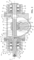
- An electrically-powered recirculating-ball steering gear assembly 20 for steering a vehicle includes a main housing 22 that has a first side wall 24 and a second side wall 26 parallel and spaced from the first side wall 24 along a axis A to establish a chamber 28 therebetween.
- the first side wall 24 has a first worm opening 30 disposed on the axis A.
- the second side wall 26 has a second worm opening 32 disposed on the axis A.
- a first side housing 34 is connected to the first side wall 24 around the first worm opening 30 in the main housing 22.
- the first side housing 34 has a protrusion 36 opposite the first worm opening 30.
- a second side housing 38 is connected to the main housing 22 through the second worm opening 32 and shares the second side wall 26 with the main housing 22.
- the second side housing 38 has an input wall 40 located parallel to and opposite the second side wall 26.
- the input wall 40 has an input opening 42 spaced opposite the second worm opening 32 along the axis A.
- a low friction bearing 44 is disposed in each of the worm openings 30, 32 and the input opening 42 and the protrusion 36.
- a worm shaft 46 extends along the axis A in the chamber 28 and through the low friction bearings 44 in each of the worm openings 30 , 32 of the main housing 22 .
- the worm shaft 46 has a worm groove 48 that extends helically to establish a worm section 50 disposed in the chamber 28 .
- the worm shaft 46 has a first end section 52 that extends from the worm section 50 and into the low friction bearing 44 in the first worm opening 30 and into the first side housing 34.
- the worm shaft 46 has a second end section 54 that has a worm end 56 adjacent the worm section 50 and extends from the worm end 56 and into the low friction bearing 44 in the second worm opening 32 and into the second side housing 38 ,
- a ball nut 58 is disposed about a portion of the worm section 50 of the worm shaft 46 and has ball raceways 60 that face the worm section 50 of the worm shaft 46 established helically within the ball nut 58.
- a plurality of ball bearings 62 that are spherical in shape are disposed in the worm grooves 48 of the worm section 50 of the worm shaft 46 and in the ball raceways 60 of the ball nut 58 ,
- a first recirculating ball mechanism 64 is disposed within the ball nut 58 to recirculate the plurality of ball bearings 62 once the plurality of ball bearings 62 rotate about the worm section 50 two and a half times.
- a second recirculating ball mechanism 66 is disposed adjacent to the first recirculating ball mechanism 64 within the ball nut 58 to recirculate the plurality of ball bearings 62 once the plurality of ball bearings 62 rotate about the worm section 50 two and a half times.
- An output shaft 68 for driving a Pitman arm has an output teeth set 70 disposed radially on the output shaft 68.
- a nut teeth set 72 extends from the ball nut 58 and engages the output teeth set 70 to move the ball nut 58 linearly along the axis A and to rotate the output shaft 68 in response to the rotation of the worm shaft 46.
- the worm shaft 46 has a worm bore 74 within the second end section 54 of the worm shaft 46 along the axis A and closed at the worm end 56 of the second end section 54 of the worm shaft 46.
- An input shaft 76 responsive to rotation of a steering wheel extends from the second end section 54 of the worm shaft 46 along the axis A and through the low friction bearing 44 in the input opening 42 to an input end 78 and has an input bore 80 within the input shaft 76 along the axis A that is closed at the input end 78 of the input shaft 76.
- There is a lost motion connection 82 between the input shaft 76 and the second end section 54 of the worm shaft 46 that allows relative lost motion of three to four degrees between the input shaft 76 and the worm shaft 46.
- a torsion bar 84 extends axially within the input bore 80 and the worm bore 74 and interconnects the input shaft 76 and the worm shaft 46 for biasing against the relative lost motion and has a first torsion end 86 and a second torsion end 88 disposed opposite each other.
- a first pin 90 extends transversally to the axis A and connects the first torsion end 86 of the torsion bar 84 to the input end 78 of the input shaft 76.
- a second pin 92 extends transversally to the axis A and connects the second torsion end 88 of the torsion bar 84 to the worm end 56 of the second end section 54 of the worm shaft 46.
- a torque sensor 94 is disposed about the input shaft 76 for measuring the torque in the input shaft 76 and communicating the torque to the electronic control unit 96,
- a first drive system 98 is in the first side housing 34 to provide a steering force in response to a primary steering input.
- the first drive system 98 includes a first gear set 100 disposed in the first side housing 34 and in driving engagement with the first end section 52 of the worm shaft 46 and a first motor 102 supported by the first side housing 34 and connected to the first gear set 100 and responsive to an electrical signal to rotate the worm shaft 46.
- a second drive system 104 for providing a steering force in response to a secondary steering input includes a second motor 106 for redundantly steering the vehicle and a second gear set 108 in driving engagement with the second motor 106 for receiving mechanical input from the second motor 106.
- the second drive system 104 is mounted in the second side housing 38 and is in driving engagement with the second end section 54 of the worm shaft 46.
- the worm section 50 of the worm shaft 46 is disposed between the first drive system 98 on the first end section 52 of the worm shaft 46 and the second drive system 104 on the second end section 54 of the worm shaft 46. Placing the drive systems in parallel allows for reduced complexity and a reduction in packaging footprint relative to placing the drive systems in series,
- the first gear set 100 of first drive system 98 is a worm reducer 110 that includes a worm gear 112 and a spur gear 114.
- the second gear set 108 of the second gear system is also a worm reducer 110 that includes a worm gear 112 and a spur gear 114.
- the first gear set 100 of the first drive system 98 is a planetary gear group 116 and the first motor 102 is mounted coaxially with the worm shaft 46 .
- the second gear set 108 of the second gear system is also a planetary gear group 116 and the second motor 106 is also mounted coaxially with the worm shaft 46.
- the first gear set 100 of the first drive system 98 is a planetary gear group 116 and the first motor 102 is mounted coaxially with the worm shaft 46.
- the second gear set 108 of the second gear system is a worm reducer 110 that includes a worm gear 112 and a spur gear 114.
- the first gear set 100 of first drive system 98 is a worm reducer 110 that includes a worm gear 112 and a spur gear 114.
- the second gear set 108 of the second gear system is a planetary gear group 116 and the second motor 106 is mounted coaxially with the worm shaft 46,
- An electronic control unit 96 is electrically connected to the first motor 102 for responding to vehicle sensors and processors to control the amount of torque of the first motor 102 to apply to the worm shaft 46 to produce the required movement of the output shaft 68 to turn the wheels of the vehicle.
Landscapes
- Engineering & Computer Science (AREA)
- Mechanical Engineering (AREA)
- Chemical & Material Sciences (AREA)
- Combustion & Propulsion (AREA)
- Transportation (AREA)
- General Engineering & Computer Science (AREA)
- Power Steering Mechanism (AREA)
- Gear Transmission (AREA)
Claims (4)
- Elektrisch angetriebene Kugelumlauf-Lenkgetriebe-Baugruppe (20) zum Lenken eines Fahrzeugs, wobei die Baugruppe (20) umfasst:eine Schneckenwelle (46), die sich entlang einer Achse (A) erstreckt und eine Schneckennut (48) enthält, die sich schraubenförmig erstreckt, um einen Schneckenabschnitt (50) zu bilden,wobei die Schneckenwelle (46) einen ersten Endabschnitt (52) und einen zweiten Endabschnitt (54) aufweist, der sich von dem Schneckenabschnitt (50) erstreckt,ein erstes Antriebssystem (98) in drehbarem Antriebseingriff mit dem ersten Endabschnitt (52) der Schneckenwelle (46) zum Lenken des Fahrzeugs durch Drehen der Schneckenwelle (46),ein zweites Antriebssystem (104) zum Bereitstellen einer Lenkkraft in Reaktion auf eine sekundäre Lenkungseingabe,wobei das zweite Antriebssystem (104) in drehbarem Antriebseingriff mit dem zweiten Endabschnitt (54) der Schneckenwelle (46) steht, um das Fahrzeug durch Drehen der Schneckenwelle (46) redundant zu lenken,wobei der Schneckenabschnitt (50) der Schneckenwelle (46) zwischen dem ersten Antriebssystem (98), das an dem ersten Endabschnitt (52) der Schneckenwelle (46) angeordnet ist, und dem zweiten Antriebssystem (104), das an dem zweiten Endabschnitt (54) der Schneckenwelle (46) angeordnet ist, angeordnet ist;gekennzeichnet durcheine Eingangswelle (76), die auf die Drehung eines Lenkrads reagiert, sich erstreckend entlang der Achse (A) von dem zweiten Endabschnitt (54) der Schneckenwelle (46),eine Leerlaufverbindung (82) zwischen der Eingangswelle (76) und der Schneckenwelle (46), um einen relativen Leerlauf zwischen der Eingangswelle (76) und der Schneckenwelle (46) unabhängig von den Antriebssystemen (98, 104) zu ermöglichen;wobei die Schneckenwelle (46) eine Schneckenbohrung (74) definiert, die sich entlang der Achse (A) innerhalb des zweiten Endabschnitts (54) erstreckt und an einem Schneckenende (56) des zweiten Endabschnitts (54) geschlossen ist,wobei die Eingangswelle (78) eine Eingangsbohrung (80) definiert, die sich entlang der Achse (A) erstreckt und an einem Eingangsende (78) der Eingangswelle (78) geschlossen ist,einen Torsionsstab (84), der sich axial innerhalb der Eingangsbohrung (80) und der Schneckenwelle (74) zwischen einem ersten Torsionsende (86) und einem zweiten Torsionsende (88) erstreckt, wobei der Torsionsstab (84) die Eingangswelle (76) und die Schneckenwelle (46) miteinander verbindet, um eine Vorspannung gegen den relativen Leerlauf zu erzeugen,einen ersten Stift (90), der das erste Torsionsende (86) des Torsionsstabes (84) mit der Eingangswelle (76) verbindet,einen zweiten Stift (92), der das zweite Torsionsende (88) des Torsionsstabes (84) mit dem zweiten Endabschnitt (54) der Schneckenwelle (46) verbindet, undeinen Drehmomentsensor (94), der um die Eingangswelle (76) herum angeordnet ist, um das Drehmoment in der Eingangswelle (76) zu messen und das Drehmoment an eine elektronische Steuereinheit (96) zu übermitteln,wobei eines der Antriebssysteme (98, 104) einen Motor (102, 106) zum drehenden Antrieb der Schneckenwelle (46) und eine Schneckenreduzierung (110) enthält, die ein Schneckengetriebe (112) und ein Stirnradgetriebe (114) enthält, verbindend den Motor (102, 106) mit der Schneckenwelle (46), um die Schneckenwelle (46) drehend anzutreiben.
- Baugruppe (20) nach Anspruch 1, wobei eines der Antriebssysteme (98, 104) einen Motor (102, 106) zum drehenden Antrieb der Schneckenwelle (46) und eine Planetengetriebegruppe (116) enthält, die den Motor (102, 106) mit der Schneckenwelle (46) verbindet, um die Schneckenwelle (46) drehend anzutreiben, wobei der Motor (102, 106) koaxial zu der Schneckenwelle (46) montiert ist.
- Baugruppe (20) nach Anspruch 1, ferner umfassend:ein Hauptgehäuse (22) mit einer ersten Seitenwand (24) und einer zweiten Seitenwand (26), die parallel und beabstandet von der ersten Seitenwand (24) entlang der Achse (A) angeordnet ist, um dazwischen eine Kammer (28) zu bilden,wobei die erste Seitenwand (24) eine erste Schneckenöffnung (30) aufweist, die auf der Achse (A) angeordnet ist,wobei die zweite Seitenwand (26) eine zweite Schneckenöffnung (32) aufweist, die auf der Achse (A) angeordnet ist,ein erstes Seitengehäuse (34), das mit der ersten Seitenwand (24) um die erste Schneckenöffnung (30) herum in dem Hauptgehäuse (22) verbunden ist,wobei das erste Seitengehäuse (34) einen Vorsprung (36) gegenüber der ersten Schneckenöffnung (30) aufweist,ein zweites Seitengehäuse (38), das mit dem Hauptgehäuse (22) durch die zweite Schneckenöffnung (32) verbunden ist und die zweite Seitenwand (26) mit dem Hauptgehäuse (22) teilt,wobei das zweite Seitengehäuse (38) eine Eingangswand (40) aufweist, die sich parallel zu und gegenüber der zweiten Seitenwand (26) befindet,wobei die Eingangswand (40) eine Eingangsöffnung (42) aufweist, die entlang der Achse (A) gegenüber der zweiten Schneckenöffnung (32) beabstandet ist,ein reibungsarmes Lager (44), das in jeder der Schneckenöffnungen (30, 32) und der Eingangsöffnung (42) und dem Vorsprung (36) angeordnet ist,wobei sich die Schneckenwelle (46) in der Kammer (28) und durch die reibungsarmen Lager (44) in jeder der Schneckenöffnungen (30, 32) des Hauptgehäuses (22) erstreckt,wobei der Schneckenabschnitt (50) der Schneckenwelle (46) in der Kammer (28) angeordnet ist,wobei sich der erste Endabschnitt (52) der Schneckenwelle (46) in das reibungsarme Lager (44) in der ersten Schneckenöffnung (30) und in das erste Seitengehäuse (34) erstreckt,wobei das erste Antriebssystem (98) angrenzend an das erste Seitengehäuse (34) angeordnet ist und enthälteinen ersten Getriebesatz (100), der in dem ersten Seitengehäuse (34) angeordnet ist und den drehbaren Antriebseingriff mit dem ersten Endabschnitt (52) der Schneckenwelle (46) bildet, undeinen ersten Motor (102), der von dem ersten Seitengehäuse (34) getragen wird und mit dem ersten Getriebesatz (100) verbunden ist und auf ein elektrisches Signal zum Drehen der Schneckenwelle (46) reagiert,wobei der zweite Endabschnitt (54) der Schneckenwelle (46) ein Schneckenende (56) aufweist, das an den Schneckenabschnitt (50) angrenzt, und sich von dem Schneckenende (56) und in das reibungsarme Lager (44) in der zweiten Schneckenöffnung (32) und in das zweite Seitengehäuse (38) erstreckt,eine Kugelmutter (58), die um einen Abschnitt des Schneckenabschnitts (50) der Schneckenwelle (46) herum angeordnet ist und Kugellaufbahnen (60) aufweist, die dem Schneckenabschnitt (50) der Schneckenwelle (46) zugewandt sind und schraubenförmig innerhalb der Kugelmutter (58) gebildet sind,mehrere Kugellager (62), die jeweils kugelförmig sind und in den Schneckennuten (48) des Schneckenabschnitts (50) der Schneckenwelle (46) und in den Kugellaufbahnen (60) der Kugelmutter (58) angeordnet sind,einen ersten Kugelumlaufmechanismus (64), der innerhalb der Kugelmutter (58) angeordnet ist, um die mehreren Kugellager (62) umlaufen zu lassen, sobald sich die mehreren Kugellager (62) zweieinhalb Mal um den Schneckenabschnitt (50) herum drehen,einen zweiten Kugelumlaufmechanismus (66), der angrenzend an den ersten Kugelumlaufmechanismus (64) innerhalb der Kugelmutter (58) angeordnet ist, um die mehreren Kugellager (62) umlaufen zu lassen, sobald die mehreren Kugellager (62) zweieinhalb Mal um den Schneckenabschnitt (50) herum rotieren,eine Ausgangswelle (68) zum Antreiben eines Lenkhebels mit einem Ausgangszahnsatz (70), der radial auf der Ausgangswelle (68) angeordnet ist,einen Mutterzahnsatz (72), der sich von der Kugelmutter (58) erstreckt und in den Ausgangszahnsatz (70) eingreift, um die Kugelmutter (58) linear entlang der Achse (A) zu bewegen und die Ausgangswelle (68) in Reaktion auf die Drehung der Schneckenwelle (46) zu drehen,wobei die elektronische Steuereinheit (96) elektrisch mit dem ersten Motor (102) verbunden ist, um auf Fahrzeugsensoren und -prozessoren anzusprechen und die Höhe des Drehmoments des ersten Motors (102) zu steuern, das auf die Schneckenwelle (46) aufgebracht werden soll, um die erforderliche Bewegung der Ausgangswelle (68) zu erzeugen, um die Räder des Fahrzeugs zu drehen,wobei das zweite Antriebssystem (104) angrenzend an dem zweiten Seitengehäuse (38) montiert ist und enthälteinen zweiten Motor (106) zum redundanten Lenken des Fahrzeugs, undeinen zweiten Getriebesatz (108) in drehbarem Antriebseingriff mit dem zweiten Motor (106) zum Empfangen von mechanischem Eingang von dem zweiten Motor (106), undwobei der Schneckenabschnitt (50) der Schneckenwelle (46) zwischen dem ersten Antriebssystem (98), das angrenzend an den ersten Endabschnitt (52) der Schneckenwelle (46) angeordnet ist, und dem zweiten Antriebssystem (104), das angrenzend an den zweiten Endabschnitt (54) der Schneckenwelle (46) angeordnet ist, angeordnet ist.
- Baugruppe (20) nach Anspruch 1, wobei
der Motor (102, 106) senkrecht zu sowohl dem Stirnradgetriebe (114) als auch der Schneckenwelle (46) montiert ist und in Antriebseingriff mit dem Schneckengetriebe (112) steht.
Applications Claiming Priority (2)
| Application Number | Priority Date | Filing Date | Title |
|---|---|---|---|
| US201762462953P | 2017-02-24 | 2017-02-24 | |
| PCT/US2018/019698 WO2018157051A1 (en) | 2017-02-24 | 2018-02-26 | Electrically-powered recirculating-ball steering gear assembly |
Publications (3)
| Publication Number | Publication Date |
|---|---|
| EP3585673A1 EP3585673A1 (de) | 2020-01-01 |
| EP3585673C0 EP3585673C0 (de) | 2025-05-14 |
| EP3585673B1 true EP3585673B1 (de) | 2025-05-14 |
Family
ID=63246043
Family Applications (1)
| Application Number | Title | Priority Date | Filing Date |
|---|---|---|---|
| EP18710250.4A Active EP3585673B1 (de) | 2017-02-24 | 2018-02-26 | Elektrisch angetriebene kugelumlauflenkgetriebeanordnung |
Country Status (5)
| Country | Link |
|---|---|
| US (1) | US10647346B2 (de) |
| EP (1) | EP3585673B1 (de) |
| CN (1) | CN110869264A (de) |
| BR (1) | BR112019017674B1 (de) |
| WO (1) | WO2018157051A1 (de) |
Families Citing this family (29)
| Publication number | Priority date | Publication date | Assignee | Title |
|---|---|---|---|---|
| FR3071784B1 (fr) * | 2017-09-29 | 2019-10-18 | Faurecia Sieges D'automobile | Mecanisme de reglage a vis, glissiere comportant un tel mecanisme de reglage et siege comportant une telle glissiere. |
| US11440580B2 (en) | 2018-06-01 | 2022-09-13 | Mando Corporation | Electric power steering apparatus and control method for the same, apparatus for synchronization dual steering motor and method i'hereof |
| WO2020004897A1 (ko) * | 2018-06-29 | 2020-01-02 | 주식회사 만도 | 전동식 조향장치 |
| KR102104456B1 (ko) * | 2018-09-21 | 2020-04-24 | 주식회사 만도 | 전동식 동력 보조 조향장치 |
| KR102109341B1 (ko) * | 2018-09-21 | 2020-05-12 | 주식회사 만도 | 전동식 동력 보조 조향장치 |
| KR102093853B1 (ko) * | 2018-09-05 | 2020-03-26 | 주식회사 만도 | 전동식 파워 스티어링 장치 및 그 제어 방법 |
| KR102098050B1 (ko) * | 2018-09-06 | 2020-04-07 | 주식회사 만도 | 전동식 파워 스티어링 장치 및 그 제어 방법 |
| US11524717B2 (en) | 2018-09-05 | 2022-12-13 | Mando Corporation | Electric power steering apparatus and control method thereof |
| KR102106292B1 (ko) * | 2018-10-05 | 2020-05-04 | 주식회사 만도 | 스티어 바이 와이어식 조향장치 |
| DE102018127204B4 (de) * | 2018-10-31 | 2024-12-05 | Knorr-Bremse Systeme für Nutzfahrzeuge GmbH | Kugelumlauflenkung |
| TWI822855B (zh) * | 2018-11-26 | 2023-11-21 | 瑞士商Mps微精密系統股份公司 | 角傳動裝置 |
| KR102167914B1 (ko) * | 2019-05-14 | 2020-10-20 | 주식회사 만도 | 자동차 조향장치 |
| DE102019127953B4 (de) * | 2019-10-16 | 2025-12-24 | Knorr-Bremse Systeme für Nutzfahrzeuge GmbH | Lenkgetriebe für ein elektromechanisches Lenksystem für ein Fahrzeug und elektromechanisches Lenksystem für ein Fahrzeug |
| US11628825B2 (en) * | 2019-10-25 | 2023-04-18 | China Automotive Systems, Inc. | Method and system for compensating excessive NVH in a vehicle front suspension |
| US11345396B2 (en) * | 2020-02-18 | 2022-05-31 | Zf Active Safety And Electronics Us Llc | Modular power steering apparatus |
| US11827290B2 (en) * | 2020-11-02 | 2023-11-28 | Ford Global Technologies, Llc | Rotary assist apparatus for recirculating ball steering gears |
| US11685426B2 (en) * | 2020-11-30 | 2023-06-27 | Zf Friedrichshafen Ag | Apparatus for use in turning steerable vehicle wheels |
| US11873037B2 (en) | 2021-03-04 | 2024-01-16 | Ford Global Technologies, Llc | Belt driven rotary assist apparatus for recirculating ball steering gears |
| KR102861727B1 (ko) * | 2021-03-25 | 2025-09-18 | 에이치엘만도 주식회사 | 조향장치 및 그 조립방법 |
| KR20230021931A (ko) * | 2021-08-06 | 2023-02-14 | 에이치엘만도 주식회사 | 전동식 동력 보조 조향장치 |
| US20230052313A1 (en) * | 2021-08-13 | 2023-02-16 | China Automotive Systems, Inc. | Electric steering assemblies for commercial vehicles |
| DE102021210741A1 (de) * | 2021-09-27 | 2023-03-30 | Robert Bosch Gesellschaft mit beschränkter Haftung | Lenkgetriebe für ein Lenksystem eines Nutzfahrzeugs |
| DE102021213067A1 (de) | 2021-11-22 | 2023-05-25 | Zf Friedrichshafen Ag | Lenkantrieb für eine Lenkachse eines lenkbaren Fahrzeugs, Lenkachse und Flurförderzeug |
| DE102021213063B4 (de) | 2021-11-22 | 2023-08-03 | Zf Friedrichshafen Ag | Lenkantrieb für eine Lenkachse eines lenkbaren Fahrzeugs, Lenkachse und Flurförderzeug |
| CN115071806B (zh) * | 2022-04-17 | 2023-09-01 | 浙江世宝股份有限公司 | 一种商用车用螺杆螺母总成内循环结构 |
| CN116279762A (zh) * | 2023-01-13 | 2023-06-23 | 陕西国力信息技术有限公司 | 双驱动动力转向系统 |
| US20240300570A1 (en) * | 2023-03-09 | 2024-09-12 | Ford Global Technologies, Llc | Rotary assist apparatus for recirculating ball steering gears |
| US12077219B1 (en) | 2023-06-23 | 2024-09-03 | Ford Global Technologies, Llc | Rotary steering systems |
| CN117087748A (zh) * | 2023-08-22 | 2023-11-21 | 杭州世宝汽车方向机有限公司 | 电动助力转向器 |
Citations (1)
| Publication number | Priority date | Publication date | Assignee | Title |
|---|---|---|---|---|
| US20070278031A1 (en) * | 2004-03-15 | 2007-12-06 | Per-Erik Andersson | Linear Electromechanical Actuator For A Steering System Of A Motor Vehicle |
Family Cites Families (18)
| Publication number | Priority date | Publication date | Assignee | Title |
|---|---|---|---|---|
| US2248251A (en) * | 1939-04-14 | 1941-07-08 | Glenn S Reeves | Automobile steering apparatus |
| GB2151996B (en) | 1983-12-09 | 1987-04-23 | Trw Cam Gears Ltd | Power assisted steering system |
| JP2582378Y2 (ja) * | 1992-02-04 | 1998-09-30 | 株式会社ユニシアジェックス | 電動パワーステアリング装置 |
| US6382342B1 (en) | 2000-06-20 | 2002-05-07 | Trw Inc. | Hydraulically powered steering apparatus with electrically powered backup |
| US7014008B2 (en) * | 2002-06-27 | 2006-03-21 | Honda Giken Kogyo Kabushiki Kaisha | Steering system for vehicle |
| US6776252B1 (en) | 2003-01-24 | 2004-08-17 | Visteon Global Technologies, Inc. | Steer-by-wire system and method for actuating road wheels of a vehicle |
| JP4285310B2 (ja) * | 2004-04-16 | 2009-06-24 | トヨタ自動車株式会社 | 車両の操舵装置 |
| CN100398373C (zh) * | 2005-03-17 | 2008-07-02 | 北京理工大学 | 循环球式电动助力转向器 |
| CN101054094A (zh) * | 2007-05-24 | 2007-10-17 | 上海交大神舟汽车设计开发有限公司 | 一种电动助力转向系统转向轴 |
| CN101700786B (zh) * | 2009-11-09 | 2012-08-29 | 南京航空航天大学 | 具有变传动比功能的客车循环球式电动助力转向系统的控制方法 |
| CN101973311B (zh) * | 2010-10-13 | 2012-05-23 | 株洲易力达机电有限公司 | 整体主动式电动助力转向机械结构 |
| US8360197B2 (en) | 2011-03-23 | 2013-01-29 | GM Global Technology Operations LLC | Recirculating ball power steering system |
| CN102717827A (zh) * | 2012-07-11 | 2012-10-10 | 曾忠敏 | 一种主动式电动助力循环球式转向系统 |
| WO2014054265A1 (ja) * | 2012-10-03 | 2014-04-10 | 日産自動車株式会社 | ステアリング制御装置、ステアリング制御方法 |
| DE102013219987A1 (de) * | 2013-10-02 | 2015-04-02 | Zf Lenksysteme Gmbh | Lenkung für ein Kraftfahrzeug |
| CN203946160U (zh) * | 2014-05-09 | 2014-11-19 | 安徽霍山县东湖汽车贸易有限公司 | 一种汽车电动助力转向系统 |
| JP2018020743A (ja) * | 2016-08-05 | 2018-02-08 | 株式会社ジェイテクト | 車両用操舵装置 |
| CN106379404B (zh) * | 2016-10-09 | 2018-09-11 | 中国北方车辆研究所 | 一种重型循环球式双模电动动力转向装置 |
-
2018
- 2018-02-26 CN CN201880025385.3A patent/CN110869264A/zh active Pending
- 2018-02-26 BR BR112019017674-8A patent/BR112019017674B1/pt active IP Right Grant
- 2018-02-26 US US15/904,934 patent/US10647346B2/en active Active
- 2018-02-26 EP EP18710250.4A patent/EP3585673B1/de active Active
- 2018-02-26 WO PCT/US2018/019698 patent/WO2018157051A1/en not_active Ceased
Patent Citations (1)
| Publication number | Priority date | Publication date | Assignee | Title |
|---|---|---|---|---|
| US20070278031A1 (en) * | 2004-03-15 | 2007-12-06 | Per-Erik Andersson | Linear Electromechanical Actuator For A Steering System Of A Motor Vehicle |
Also Published As
| Publication number | Publication date |
|---|---|
| WO2018157051A1 (en) | 2018-08-30 |
| US20180244305A1 (en) | 2018-08-30 |
| CN110869264A (zh) | 2020-03-06 |
| BR112019017674B1 (pt) | 2023-10-24 |
| US10647346B2 (en) | 2020-05-12 |
| EP3585673C0 (de) | 2025-05-14 |
| EP3585673A1 (de) | 2020-01-01 |
| BR112019017674A2 (pt) | 2020-03-31 |
| WO2018157051A8 (en) | 2019-09-06 |
Similar Documents
| Publication | Publication Date | Title |
|---|---|---|
| EP3585673B1 (de) | Elektrisch angetriebene kugelumlauflenkgetriebeanordnung | |
| US9151371B2 (en) | Ball screw device having tunnel raceway | |
| US10421481B2 (en) | Utility vehicle steering system | |
| EP2110580B1 (de) | Kugelumlaufspindelmechanismus und elektrische Servolenkvorrichtung, die diesen Mechanismus verwendet | |
| EP2713078B1 (de) | Angetriebene Riemenscheibe aus Nylonharz | |
| US8960037B2 (en) | Ball screw device, linear actuator and vehicle steering system | |
| WO2018079540A1 (ja) | 電動アクチュエータ | |
| CN106005003A (zh) | 动力转向设备 | |
| US11465673B2 (en) | Motor-assisted steering ball-screw | |
| CN101258066A (zh) | 转向装置以及其所使用的运动转换装置 | |
| US20210387667A1 (en) | Steering apparatus | |
| EP3534507A1 (de) | Elektrischer aktuator | |
| US8245814B2 (en) | Transmission ratio variable mechanism and vehicle steering apparatus | |
| WO2016129436A1 (ja) | 後輪転舵装置 | |
| US6637541B2 (en) | Steering system having an interlocking mechanism | |
| EP2308742B1 (de) | Variabler getriebeübersetzungsmechanismus und lenkvorrichtung mit variabler übersetzung | |
| CN113734273A (zh) | 车辆的转向器、转向系统和车辆 | |
| US20250121879A1 (en) | Rotation-limiting device and steering device | |
| US20030221897A1 (en) | Rear wheel steering device for a vehicle | |
| US7694601B2 (en) | Gear device and electric power steering apparatus | |
| JP4516479B2 (ja) | 回転直動変換機構 | |
| JP4016815B2 (ja) | 電動パワーステアリング装置 | |
| KR101622510B1 (ko) | 자동차 조향장치의 유성기어 감속기 | |
| JP2013193565A (ja) | 電動パワーステアリング装置 | |
| JP2012006515A (ja) | 車両用操舵装置 |
Legal Events
| Date | Code | Title | Description |
|---|---|---|---|
| STAA | Information on the status of an ep patent application or granted ep patent |
Free format text: STATUS: UNKNOWN |
|
| STAA | Information on the status of an ep patent application or granted ep patent |
Free format text: STATUS: THE INTERNATIONAL PUBLICATION HAS BEEN MADE |
|
| PUAI | Public reference made under article 153(3) epc to a published international application that has entered the european phase |
Free format text: ORIGINAL CODE: 0009012 |
|
| STAA | Information on the status of an ep patent application or granted ep patent |
Free format text: STATUS: REQUEST FOR EXAMINATION WAS MADE |
|
| 17P | Request for examination filed |
Effective date: 20190814 |
|
| AK | Designated contracting states |
Kind code of ref document: A1 Designated state(s): AL AT BE BG CH CY CZ DE DK EE ES FI FR GB GR HR HU IE IS IT LI LT LU LV MC MK MT NL NO PL PT RO RS SE SI SK SM TR |
|
| AX | Request for extension of the european patent |
Extension state: BA ME |
|
| DAV | Request for validation of the european patent (deleted) | ||
| DAX | Request for extension of the european patent (deleted) | ||
| STAA | Information on the status of an ep patent application or granted ep patent |
Free format text: STATUS: EXAMINATION IS IN PROGRESS |
|
| 17Q | First examination report despatched |
Effective date: 20200907 |
|
| GRAP | Despatch of communication of intention to grant a patent |
Free format text: ORIGINAL CODE: EPIDOSNIGR1 |
|
| STAA | Information on the status of an ep patent application or granted ep patent |
Free format text: STATUS: GRANT OF PATENT IS INTENDED |
|
| INTG | Intention to grant announced |
Effective date: 20250207 |
|
| GRAS | Grant fee paid |
Free format text: ORIGINAL CODE: EPIDOSNIGR3 |
|
| GRAA | (expected) grant |
Free format text: ORIGINAL CODE: 0009210 |
|
| STAA | Information on the status of an ep patent application or granted ep patent |
Free format text: STATUS: THE PATENT HAS BEEN GRANTED |
|
| AK | Designated contracting states |
Kind code of ref document: B1 Designated state(s): AL AT BE BG CH CY CZ DE DK EE ES FI FR GB GR HR HU IE IS IT LI LT LU LV MC MK MT NL NO PL PT RO RS SE SI SK SM TR |
|
| REG | Reference to a national code |
Ref country code: GB Ref legal event code: FG4D |
|
| REG | Reference to a national code |
Ref country code: CH Ref legal event code: EP |
|
| REG | Reference to a national code |
Ref country code: IE Ref legal event code: FG4D |
|
| U01 | Request for unitary effect filed |
Effective date: 20250514 |
|
| U07 | Unitary effect registered |
Designated state(s): AT BE BG DE DK EE FI FR IT LT LU LV MT NL PT RO SE SI Effective date: 20250520 |
|
| PG25 | Lapsed in a contracting state [announced via postgrant information from national office to epo] |
Ref country code: ES Free format text: LAPSE BECAUSE OF FAILURE TO SUBMIT A TRANSLATION OF THE DESCRIPTION OR TO PAY THE FEE WITHIN THE PRESCRIBED TIME-LIMIT Effective date: 20250514 |
|
| PG25 | Lapsed in a contracting state [announced via postgrant information from national office to epo] |
Ref country code: GR Free format text: LAPSE BECAUSE OF FAILURE TO SUBMIT A TRANSLATION OF THE DESCRIPTION OR TO PAY THE FEE WITHIN THE PRESCRIBED TIME-LIMIT Effective date: 20250815 Ref country code: NO Free format text: LAPSE BECAUSE OF FAILURE TO SUBMIT A TRANSLATION OF THE DESCRIPTION OR TO PAY THE FEE WITHIN THE PRESCRIBED TIME-LIMIT Effective date: 20250814 |
|
| PG25 | Lapsed in a contracting state [announced via postgrant information from national office to epo] |
Ref country code: PL Free format text: LAPSE BECAUSE OF FAILURE TO SUBMIT A TRANSLATION OF THE DESCRIPTION OR TO PAY THE FEE WITHIN THE PRESCRIBED TIME-LIMIT Effective date: 20250514 |
|
| PG25 | Lapsed in a contracting state [announced via postgrant information from national office to epo] |
Ref country code: HR Free format text: LAPSE BECAUSE OF FAILURE TO SUBMIT A TRANSLATION OF THE DESCRIPTION OR TO PAY THE FEE WITHIN THE PRESCRIBED TIME-LIMIT Effective date: 20250514 |
|
| PG25 | Lapsed in a contracting state [announced via postgrant information from national office to epo] |
Ref country code: RS Free format text: LAPSE BECAUSE OF FAILURE TO SUBMIT A TRANSLATION OF THE DESCRIPTION OR TO PAY THE FEE WITHIN THE PRESCRIBED TIME-LIMIT Effective date: 20250814 |
|
| PG25 | Lapsed in a contracting state [announced via postgrant information from national office to epo] |
Ref country code: IS Free format text: LAPSE BECAUSE OF FAILURE TO SUBMIT A TRANSLATION OF THE DESCRIPTION OR TO PAY THE FEE WITHIN THE PRESCRIBED TIME-LIMIT Effective date: 20250914 |
|
| PG25 | Lapsed in a contracting state [announced via postgrant information from national office to epo] |
Ref country code: SM Free format text: LAPSE BECAUSE OF FAILURE TO SUBMIT A TRANSLATION OF THE DESCRIPTION OR TO PAY THE FEE WITHIN THE PRESCRIBED TIME-LIMIT Effective date: 20250514 |
|
| PG25 | Lapsed in a contracting state [announced via postgrant information from national office to epo] |
Ref country code: CZ Free format text: LAPSE BECAUSE OF FAILURE TO SUBMIT A TRANSLATION OF THE DESCRIPTION OR TO PAY THE FEE WITHIN THE PRESCRIBED TIME-LIMIT Effective date: 20250514 |
|
| PG25 | Lapsed in a contracting state [announced via postgrant information from national office to epo] |
Ref country code: SK Free format text: LAPSE BECAUSE OF FAILURE TO SUBMIT A TRANSLATION OF THE DESCRIPTION OR TO PAY THE FEE WITHIN THE PRESCRIBED TIME-LIMIT Effective date: 20250514 |
|
| PLBE | No opposition filed within time limit |
Free format text: ORIGINAL CODE: 0009261 |
|
| STAA | Information on the status of an ep patent application or granted ep patent |
Free format text: STATUS: NO OPPOSITION FILED WITHIN TIME LIMIT |
|
| REG | Reference to a national code |
Ref country code: CH Ref legal event code: L10 Free format text: ST27 STATUS EVENT CODE: U-0-0-L10-L00 (AS PROVIDED BY THE NATIONAL OFFICE) Effective date: 20260325 |