EP3584511B1 - Lüftungsgerät mit schalldämpferaufsatz - Google Patents
Lüftungsgerät mit schalldämpferaufsatz Download PDFInfo
- Publication number
- EP3584511B1 EP3584511B1 EP19000070.3A EP19000070A EP3584511B1 EP 3584511 B1 EP3584511 B1 EP 3584511B1 EP 19000070 A EP19000070 A EP 19000070A EP 3584511 B1 EP3584511 B1 EP 3584511B1
- Authority
- EP
- European Patent Office
- Prior art keywords
- air
- air duct
- air guide
- silencer
- sound insulation
- Prior art date
- Legal status (The legal status is an assumption and is not a legal conclusion. Google has not performed a legal analysis and makes no representation as to the accuracy of the status listed.)
- Active
Links
Images







Classifications
-
- F—MECHANICAL ENGINEERING; LIGHTING; HEATING; WEAPONS; BLASTING
- F24—HEATING; RANGES; VENTILATING
- F24F—AIR-CONDITIONING; AIR-HUMIDIFICATION; VENTILATION; USE OF AIR CURRENTS FOR SCREENING
- F24F13/00—Details common to, or for air-conditioning, air-humidification, ventilation or use of air currents for screening
- F24F13/24—Means for preventing or suppressing noise
-
- F—MECHANICAL ENGINEERING; LIGHTING; HEATING; WEAPONS; BLASTING
- F24—HEATING; RANGES; VENTILATING
- F24F—AIR-CONDITIONING; AIR-HUMIDIFICATION; VENTILATION; USE OF AIR CURRENTS FOR SCREENING
- F24F13/00—Details common to, or for air-conditioning, air-humidification, ventilation or use of air currents for screening
- F24F13/24—Means for preventing or suppressing noise
- F24F2013/242—Sound-absorbing material
Definitions
- the invention relates to a ventilation device with a housing, a heat exchanger arranged in the housing, a supply air duct, an exhaust air duct, an exhaust air duct, an outside air duct, a first fan arranged in the supply air duct, a second fan arranged in the exhaust air duct and a silencer attachment with at least one lateral surface.
- the invention further relates to the installation of a silencer attachment on a ventilation device.
- Ventilation units particularly central ventilation units, are well-known on the market and have at least one supply air duct, one exhaust air duct, one exhaust air duct and one outside air duct.
- Central ventilation units also have a heat exchanger that extracts the heat contained in the exhaust air and uses it to heat the incoming fresh air.
- the air is conveyed by two fans, a first fan of which conveys the fresh, heated air into the living area and a second fan of which conveys the used air out of the living area.
- silencers are installed on the individual air ducts.
- the silencer can be integrated into the air duct intended for air guidance or forms a section of the ventilation duct.
- the silencer has at least two silencer segments which are arranged at a distance from one another in order to form a silencer channel between the mutually facing surfaces of the two segments, which extends from the inlet to the outlet of the silencer.
- the two segments are mounted so that they can move relative to one another in order to be able to move at least partial areas of the surfaces of the segments towards or away from one another.
- the publication EP 2642215 A1 discloses an acoustic damper for a ventilation unit having a housing comprising a plurality of walls defining an enclosure.
- a first port arrangement comprises a plurality of ports arranged in a fixed relationship to one another on a first wall of the enclosure corresponding to a position of the ports of the ventilation unit.
- a second port arrangement comprises a plurality of second ports corresponding to the plurality of first claims and arranged in a fixed relationship to one another on a second wall of the enclosure.
- the second port arrangement is configured as a connection to a ventilation shaft element.
- a plurality of fluid conduits connect each of the first ports to the corresponding second ports.
- a sound-damping material surrounds the conduits and the conduits are configured to allow sound waves to propagate from within the conduits into the sound-damping material.
- the conduits are fluidly isolated from one another to prevent air from one of the conduits from passing through the sound-damping material to another conduit.
- the publication WO 2015/033213 A1 discloses a silencer duct in a silencer unit for a heat recovery ventilation unit for supplying air to an apartment or part thereof and for extracting return air from the apartment or part thereof.
- the silencer unit comprises a silencer duct for an air supply outlet of the heat recovery ventilation unit and a silencer duct for a return air inlet of the heat recovery ventilation unit, both silencer ducts being curved and each having at least one bend.
- the publication EP 2306108 A1 discloses an arrangement for ventilating one or more rooms in a building, comprising a housing having at least four openings arranged on the same side thereof for directing exhaust air from the rooms of the building as well as supply air from outside to the rooms of the building through a rotary heat exchanger arranged in the housing.
- Fan elements are arranged within the housing for generating air flows through the housing.
- Means are arranged for directing a flow of supply air from a first of the fan elements substantially in one direction.
- Elements of sound absorbing material define a channel extending from this first fan element to an outlet of the housing.
- the invention is based on the object of proposing a ventilation device with a silencer attachment of the type mentioned at the beginning, in which the sound propagation in the living area can be reduced in a structurally simple manner.
- the object is to implement the sound insulation in the smallest possible space and to make installation easier.
- the invention is based on the idea of providing a silencer attachment for a ventilation device, which has a first, a second, a third, a fourth air guide unit with a first, a second, a third, a fourth air guide and a first, a second, a third, a fourth connection opening for connection to the supply air duct, the exhaust air duct, the exhaust air duct, the outside air duct of the ventilation device, wherein at least two air guide units, in particular the first air guide unit and the second air guide unit, have a sound insulation material.
- two air guide units of the silencer attachment in particular the first and the second air guide unit, have sound insulation for dampening sound that spreads along the air guide units through which air flows.
- the first and the second air guide unit in particular have an increased sound level due to the fans arranged in the supply air duct and in the exhaust air duct of the ventilation device.
- the first and third air duct units have soundproofing material.
- the first and third air duct units are also important in terms of preventing the spread of sound, since their fluid lines lead into the living area, where the fresh air is introduced and the used air is discharged. The aim here is to reduce disturbing noises.
- the first and fourth air guide units comprise sound insulation material.
- the third and fourth air guide units comprise sound insulation material.
- the second and third air guide units may also preferably comprise sound insulation material.
- An advantageous idea of the invention is that the air guide units of the silencer attachment have air guides.
- the first air duct has a first channel with sound insulation material
- the second air duct has a second channel with sound insulation material
- the third air duct has a third channel with sound insulation material
- the fourth air duct has a fourth channel with Soundproofing material. Because all four air ducts have soundproofing material, the sound propagation into the living area is reduced.
- the sound insulation material is preferably a closed-pore material such as polyester fleece, polyether foam, melamine foam and/or another commercially available material for sound reduction in various material thicknesses, by means of which the sound is absorbed. It is also advantageous that at least two of the above-mentioned sound insulation materials such as polyester fleece, polyether foam, melamine foam can be used in combination for sound insulation in the air duct units.
- the thicker the sound insulation material such as polyether foam, should be for effective sound insulation. Since high-mass foams should be used for sound insulation, this also means a higher weight.
- the sound insulation material has a skin coating for easy and hygienic cleaning of the surface.
- the silencer attachment has the sound insulation material inside with which the inner walls are lined.
- the soundproofing material preferably has five soundproofing elements, of which in one embodiment three soundproofing elements are provided over the entire surface of three inner walls of the four air duct units.
- the three soundproofing elements are preferably arranged outside the first, second, third and/or fourth channel of the air duct units.
- a fourth soundproofing element can preferably be provided on the fourth inner wall, which has the outlet opening for connecting the fluid line.
- a fifth soundproofing element is provided as a cover, which closes the air duct unit towards an upper surface of the silencer attachment.
- a sixth soundproofing element is arranged on a device for redirecting the air flow, in particular on the first, second, third and/or fourth deflection, in the air duct units between the connection opening and the outlet opening.
- the sound insulation material prefferably be glued to the substrate using an adhesive, preferably an assembly adhesive or a pressure-sensitive adhesive.
- the substrate corresponds to the three inner walls and the device for diverting the air flow.
- the use of adhesives can be dispensed with, provided that the four individually mounted sound insulation elements of an air duct unit are dimensioned in such a way that they press against each other during assembly and prevent fluid exchange between the individual air duct units and to the outside during operation of the ventilation unit.
- an additional layer can be provided on the coated closed-pore sound insulation material, which is easy to clean hygienically.
- an open-pored material with a porous surface such as glass fiber fleece can be used, which absorbs the sound waves.
- At least two lateral outlet openings for guiding the deflected air flow out of and/or into the air guide units are provided on at least one lateral surface of the silencer attachment.
- lateral outlet openings for guiding the redirected air flow out of and/or into the air guide units are provided on two lateral surfaces of the silencer attachment.
- the silencer attachment is preferably a cubic or cuboid-shaped attachment which has four lateral surfaces and in which preferably two air guide units are arranged opposite two further air guide units.
- four air guide units are arranged in the cuboid-shaped silencer attachment, wherein the first and third air guide units facing the living area with their two outlet openings are arranged next to one another on a common lateral surface and the second and fourth air guide units facing the outside air with their two outlet openings are also arranged next to one another on a common lateral surface which is arranged opposite the first-mentioned lateral surface of the first and third air guide units.
- the silencer attachment can also have a trapezoidal shape or another advantageous shape with at least one lateral surface.
- the at least one lateral surface of the silencer attachment which is cuboid-shaped or trapezoidal, is arranged at an angle between 20° and 160°, in particular between 45° and 90°, to the underside and/or to the upper surface of the silencer attachment and/or to the base of the ventilation device.
- the silencer attachment can also be dome-shaped, round or approximately round.
- the silencer attachment has only one side surface, so that the outlet openings are arranged on a round or curved side surface. Another advantageous embodiment than the embodiments mentioned here is also possible and covered by this.
- the upper surface has a round base and/or a dome on which no outlet opening is provided for connecting a fluid line.
- the dome is preferably arranged above the outlet openings of the silencer attachment on one side surface.
- the silencer attachment comprises the outlet openings in approximately an upper third of the lateral surface in the case of a dome-shaped, round or approximately round design of a silencer attachment.
- the air flow diverted by the air guide units and flowing through the outlet openings provided on the side surface is at an angle to the underside of the silencer attachment. This flow angle is preferably between 30° and 110°.
- At least one barrier for fluid-tight separation of the air flow is arranged between the first and the second air guide unit.
- the fact that at least one barrier is provided preferably results in four air guide units, of which two air guide units, in particular the first and the second air guide unit and the third and the fourth air guide unit, are identical. It is also advantageous that the barrier is provided between the first, the second, the third and the fourth air guide unit.
- the barrier is necessary to ensure the tightness of the four air duct units so that the various air flows, in particular from the supply air duct, the exhaust air duct, as well as the exhaust air duct and the outside air duct, are not mixed with each other.
- the barrier also prevents unwanted fluid exchange between the individual air flows and the ambient air.
- the sealing of the four air duct units by means of the barrier is preferably carried out by means of inserted metal sheets or by means of fluid-impermeable films that are sealed to the metal housing.
- a further aspect of the invention is that the first and second air guide units as well as the third and fourth air guide units comprise soundproofing material, at least two lateral outlet openings are provided on at least one lateral surface of the silencer attachment and that the barrier is provided at least between the first, the second, the third and the fourth air guide unit.
- At least one equalizing device for equalizing the air flow is provided in at least two air ducts of the air duct units, wherein the equalizing device is arranged approximately perpendicular to the flow direction of the air flow.
- the equalization device is preferably an additional layer, such as a sheet with holes.
- the sheet can be a perforated sheet or a perforated sheet.
- the additional layer is preferably applied to the soundproofing material and serves as a boundary surface between the flowing air streams and the soundproofing material, in particular in at least two air duct units. Because the additional layer limits the exit of the incoming sound waves within the soundproofing material, the sound propagation in the direction of the fluid lines and into the living spaces is prevented. Turbulent flows are equalized.
- a baffle silencer can also be provided for sound absorption.
- the first, second, third and/or fourth air guide units have at least one equalization device.
- the at least one equalization device or the perforated plate is arranged in the first air duct of the first air duct unit and in the second air duct of the second air duct unit approximately perpendicular to the flow direction of the air flow.
- an equalization device as an additional layer on the sound insulation material along the inner walls of the air duct units, parallel to the direction of air flow.
- the perforated sheet can also be arranged on at least two inner walls, preferably on five inner walls, of the air duct units.
- the first air guide unit has a first deflection
- the second air guide unit has a second deflection
- the third air guide unit has a third deflection
- the fourth air guide unit has a fourth deflection.
- first and second deflection means as well as the third and fourth deflection means have approximately equal deflection surfaces for guiding the air flow from the connection opening to the outlet opening, wherein the first and second deflection means as well as the third and the fourth deflection are of equal size and are preferably arranged mirror-symmetrically to each other in the air guide units.
- the first and second deflectors have at least two, but advantageously at least three deflection surfaces for redirecting the air flow.
- the equalization device is arranged between at least one inner wall and at least one deflection surface of the deflections.
- prefabricated sound insulation elements are used for sound absorption.
- Sound insulation elements preferably made of closed-pore sound insulation material, are arranged on top of one another with differently positioned cutouts that form the channels for fluid guidance.
- the sound insulation elements placed on top of one another form a sound insulation complex.
- the connected sound insulation complex which has the four air ducts, is inserted as a whole into the silencer attachment.
- first, the second, the third and/or the fourth air ducts comprise bulk material, in particular a plurality of bodies, for sound insulation.
- the bodies In a loose fill, the bodies have a shape that leaves a large number of irregularly shaped channels between the bodies.
- the filler bodies can be, for example, spheres, triangles, tetrapods or other shaped bodies, preferably with a closed-pore surface, which are preferably poured into the four air guide units of the silencer attachment.
- the bulk material can preferably consist of activated carbon to filter out unpleasant odors, especially from outside.
- grilles or grille plugs are also advantageous to insert grilles or grille plugs into the connection openings and outlet openings.
- the grilles or grille plugs prevent any filler from migrating into the connected fluid lines and/or into the supply air, exhaust air, outside air and exhaust air ducts of the ventilation unit.
- the grid plug preferably has a cylindrical design, with at least one end closed in a grid-like manner.
- the peripheral surface of the grid plug is preferably permeable to air through a plurality of openings.
- the grid plug can preferably have a cover made of fleece or fabric, which additionally catches fine particles, such as abrasion of the filling bodies.
- the incoming air is forced through the grilles or grille plugs into the air duct units of the silencer attachment, which are filled with filler. There, the air finds its way through the irregularly shaped gaps, where the sound is reduced, particularly by multiple reflections and compression, and leaves the silencer attachment through the additional grille or grille plug.
- This type of design with bulk material in the air duct units prevents the noise generated in the ventilation unit from being dampened and from being propagated into the piping system in the building.
- the silencer attachment with the four connection openings on its underside has the connection pattern of the connection nozzles of the supply air duct, the exhaust air duct, the exhaust air duct and the outside air duct of the ventilation unit. This ensures that the silencer attachment is positioned precisely on the connection nozzles and that installation is easier. An additional adapter that has to be placed on the ventilation unit is not required.
- the contact area between the connection openings of the silencer attachment and the connection nozzles is sealed with a sealant.
- the silencer attachment is advantageously dimensioned in such a way that it forms a visually appealing unit with the ventilation device, for example in the form of an extended tower in the vertical direction.
- the edges of the silencer attachment can thus roughly match the edges of the ventilation device, so that preferably a flush surface is formed on the outside or the outsides.
- the base area of the silencer attachment preferably has the same dimensions as the base area of the base of the ventilation device to be covered.
- the four air duct units of the silencer attachment are advantageously compact and implemented in a small space, so that the sound absorption is not particularly noticeable to an outsider.
- the silencer attachment with the connection openings is placed on a base of the ventilation device, in particular on a connection nozzle of the supply air duct, exhaust air duct, exhaust air duct, outside air duct, wherein at least two lateral outlet openings on at least one lateral surface are connected to a fluid line for guiding the air flow.
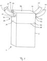
- Fig. 1 shows a central ventilation device 1 with a housing 2 and a silencer attachment 20 placed on the ventilation device 1.
- the silencer attachment 20 shown in the embodiment has four lateral surfaces 34 and an upper surface 52, wherein outlet openings 30, 31, 32, 33 are provided on two opposite lateral surfaces 34 for connection to four fluid lines 61.
- the lateral surfaces 34, the underside 29 (in Fig. 1 not shown) and the upper surface 52 is a cuboid.
- the fluid lines 61 are connected to the outlet openings 30, 31, 32, 33 via connecting flanges 51 which are inserted into the outlet openings 30, 31, 32, 33.
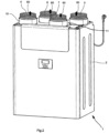
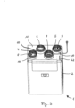
- the central ventilation unit 1 has, according to Fig. 2 and 3 , a supply air duct 4, an exhaust air duct 6, an outside air duct 7 and an exhaust air duct 5, which protrude from the base 11 of the ventilation device 1.
- the supply air duct 4, the exhaust air duct 6, the outside air duct 7 and the exhaust air duct 5 can protrude elsewhere on the ventilation device 1.
- a first fan 8 is provided in the supply air duct 4 and a second fan 9 is provided in the exhaust air duct 5.
- the supply air duct 4, the exhaust air duct 6, the outside air duct 7 and the exhaust air duct 5 have a connection piece 10 for connecting the ventilation device 1 to the silencer attachment 20.
- a cover 62 for a connection terminal is shown on the base 11, for which a connection terminal cavity 64 ( Fig. 6 ) is provided.
- Fig. 4 shows the silencer attachment 20 according to Fig. 1 , which is placed on the ventilation unit 1.
- the silencer attachment 20 has the four air guide units 21, 22, 23, 24 inside, located behind the side surfaces 34 ( Fig. 5 ).
- the silencer attachment 20 is closed from the outside with a lateral surface 34 and an upper surface 52, whereby the upper surface 52 is preferably attached or can be attached to the projections of the four lateral surfaces 34.
- the upper surface 52 is connected approximately centrally to the barrier 46 of the silencer attachment 20 located underneath via a web 59.
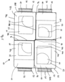
- Fig. 5 the sound insulation material 50 in the silencer attachment 1 is shown in a sectional view from above.
- the first air guide unit 21, the second air guide unit 22, the third air guide unit 23 and the fourth air guide unit 24 have the sound insulation material 50 on the inside on the inner walls.
- the embodiment shows the first sound insulation element 50a on the first inner wall 56a, the second sound insulation element 50b on the second inner wall 56b, the third sound insulation element 50c on the third inner wall 56c and the sixth sound insulation element 50f on the first, second, third and/or fourth deflection 40, 41, 42, 43 of an air guide unit 21, 22, 23, 24.
- the air guide units 21, 22, 23, 24 are separated by a barrier 46, on which a web 59 is provided for connection to the upper surface 52.
- the connection openings 25, 26, 27, 28 through which the air flow 60 flows can also be seen.
- Fig. 6 shows two opposite air guide units 21, 24 of the silencer attachment 20 in a side view.
- the first and fourth air guide units 21, 24 shown have a first inner wall 56a on the inside, which is preferably parallel to the outlet openings 30, 33 shown on a fourth inner wall 56d.
- the air guide units 21, 22, 23, 24 have a fifth inner wall 57, which is preferably parallel to the underside 29 of the silencer attachment 20 and seals the air guide unit at the top.
- the first inner wall 56a and the fifth inner wall 57 are preferably arranged at right angles to each other.
- the air guide units 21, 22, 23, 24 have a second inner wall 56b and a third inner wall 56c, which are arranged opposite one another and are formed at right angles to the first and fourth inner walls 56a, 56d.
- the first air guide unit 21 has a first air guide 36 with a first channel 36a between the connection opening 25 and the outlet opening 30.
- the fourth air guide unit 24 has a fourth air guide 39 with a fourth channel 39a between the connection opening 28 and the outlet opening 33.
- the first and second air guide units 21, 22 are provided with a thicker sound insulation material 50 compared to the third and fourth air guide units 23, 24. It is also advantageous that the air flow 60 is redirected several times at the first and second deflection 40, 41. This significantly reduces the sound propagation, especially in the first and second air guide units 21, 22.
- the soundproofing material 50 preferably has six soundproofing elements 50a, 50b, 50c, 50d, 50e, 50f, in particular five soundproofing elements 50a, 50b, 50c, 50e, 50f, of which three soundproofing elements 50a, 50b, 50c are arranged on the first, second and third inner walls 56a, 56b, 56c.
- the soundproofing element 50e is provided as an upper cover on the fifth inner wall 57.
- the soundproofing element 50f is provided on the first, second, third and/or fourth deflection 40, 41, 42, 43.
- the sound insulation material 50 has different material thicknesses d.
- the sound insulation material 50 according to Fig. 6 preferably 6 different material thicknesses, eg d1 to d6 between 5 mm and 200 mm.
- the sound insulation material for the first and second air guide units 21, 22 has a thicker material thickness d.
- At least one equalization device 48 such as a perforated plate, is provided on the first and second air guide units 21, 22, in particular on the first, second, third and/or fourth air guide units 21, 22, 23, 24, in order to standardize and/or make more uniform a turbulent air flow 60, in particular from the supply air duct 4 and the exhaust air duct 5.
- the perforated plate can be provided on each inner wall 56a, 56b, 56c, 56d, 57 and/or on the deflection 40, 41, 42, 43 within the air guide units 21, 22, 23, 24, past which the air flow 60 flows.
- the perforated plate is arranged perpendicular to the flow direction (S) of the air flow 60, in particular between the first and the fifth inner wall 56a, 57.
- the perforated plate is arranged between the first inner wall 56a and the first, the second, the third and/or the fourth deflection 40, 41, 42, 43.
- the perforated plate is provided between the second inner wall 56b and the first, second, third and/or fourth deflection 40, 41, 42, 43.
- a holder 45 for guiding the air flow 60 on the lateral surface 34 facing the outlet opening 30, 31 is provided in the first and second air guide units 21, 22.
- the holder 45 is preferably a sheet metal construction with at least two, in particular at least three, preferably four or more deflection surfaces 49.
- the holder 45 is an inclined square.
- the degree of deflection is determined in particular by the height H of the holder 45 or the distance between two opposite deflection surfaces 49.
- the holder 45 is designed as a sheet metal construction without a height H, on which the sound insulation material 50, in particular the sixth sound insulation element 50f, is arranged.
- the third and fourth deflection 42, 43 is formed by a C-shaped configuration of the soundproofing material 50 in the third and fourth air guide unit 23, 24, at which the air flow 60 flows to the outlet opening 32, 33.
- the third and fourth deflection 42, 43 preferably have at least two deflection surfaces 49.
- connection openings 25, 26, 27, 28 have a lower opening 54 and an upper opening 53 for adjusting the radius of the connection piece 10 to the air guides 36, 37, 38, 39 of the air guide units 21, 22, 23, 24 ( Fig. 6 , 7 ).
- the underside 29 of the silencer attachment 20 is formed by a sound insulation base 50g with the connection openings 25, 26, 27, 28 for connection to the ventilation unit 1.
- the sound insulation base 50g is preferably formed from an EPS or EPP.
- the sound insulation elements 50a, 50b, 50c, 50d, 50e, 50f are individually adapted to the inner walls 56a, 56b, 56c, 56d, 57 and/or deflections 40, 41, 42, 43 to be covered, they have different geometries.
- the sound insulation element 50b, 50c shown has a corner cutout 35a with a cutting edge arranged approximately perpendicular to the surface of the sound insulation element.
- the sound insulation element shown is preferably provided on a second and/or third inner wall 56b, 56c, adapted to at least two of the four deflections 40, 41, 42, 43.
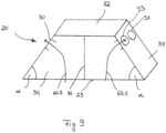
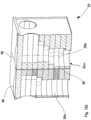
- Fig. 9 and Fig. 10 show different versions of a silencer attachment 20.
- the silencer attachment 20, in comparison to the silencer attachment version in Fig. 1 have at least one lateral surface 34 which is not perpendicular to the upper surface 52 and/or the lower surface 29.
- the silencer attachment 20 can also have curved lateral surfaces 34 on which the fluid lines 61 are arranged ( Fig. 1 ).
- the invention also comprises a silencer attachment 20 with an upper surface 52, which is designed in particular as a dome, which is not parallel to the underside 29 of the silencer attachment 20 and/or to the base 11 of the ventilation device 1.
- the silencer attachment 20 has an outer wall on at least one upper surface 52 and/or at least one lateral surface 34 for protecting the first, second, third and/or fourth air guide units 21, 22, 23, 24.
- the air flow 60 deflected by the first, second, third and/or fourth air guide unit 21, 22, 23, 24 and flowing on the lateral surface 34 through the outlet openings 30, 31, 32, 33 has an angle ⁇ to the underside 29 of the silencer attachment 20.
- This flow angle ⁇ is preferably between 30° and 110°.
- Fig. 11 shows an exploded view of the silencer attachment 20 with a plurality of sound insulation elements placed one on top of the other.
- the plurality of sound insulation elements 50i placed one on top of the other have 4 changing cutouts 35a per layer, which, when placed one on top of the other, form the four channels 36a, 37a, 38a, 39a to the outlet openings 30, 31, 32, 33.
- Fig. 12a and Fig. 12b show in a top view and a sectional view the plurality of sound insulation elements 50i placed one above the other within the air guide units 21, 22, 23, 24, which are delimited from one another by the barrier 46.
- the sound insulation elements 50i are preferably provided within the four air guide units 21, 22, 23, 24 created by the at least one barrier 46. This design is particularly advantageous because there is no fluid exchange between the four channels 36a, 37a, 38a, 39a due to the channels that are sealed off from the sheet metal housing.
- Fig. 13a, 13b, 13c show the sound insulation elements 50i, which according to Fig. 12a and 12b in a majority of cases are placed on top of each other in the air duct units, thus forming a sound insulation complex.
- the sound insulation elements 50i have cutouts 35a which are designed differently for each layer.
- Fig. 13a The sound insulation element 50i shown as an example has a cutout 35a, which represents the left half of a slot.
- the sound insulation element 50i in Fig. 13b has a cutout 35a, which is designed as an elongated hole.
- Fig. 13c shows a section 35a in a slot shape, whereby the slot is shortened and slightly offset from the slot in Fig. 13b trained.
- the cutouts 35a have cut edges 35b, in particular with an angle of between 10 and 100 degrees.
- the cut edges 35b of the sound insulation elements 50i have a skin.
- different material thicknesses d can be used. The closed-pore absorber and the gluing of the plurality of sound insulation elements 50i placed on top of one another can ensure sufficient tightness and flexible assembly.
- the cut edges 35b of the cutouts 35a are subsequently provided with a skin.
- the skin on the cut edges 35b of the sound insulation elements 50i is necessary because the air flow 60 almost only comes into contact with the cut edges 35b and not with the already skinned outer surfaces of the sound insulation elements 50i.
Landscapes
- Engineering & Computer Science (AREA)
- Chemical & Material Sciences (AREA)
- Combustion & Propulsion (AREA)
- Mechanical Engineering (AREA)
- General Engineering & Computer Science (AREA)
- Duct Arrangements (AREA)
- Exhaust Silencers (AREA)
Description
- Die Erfindung betrifft ein Lüftungsgerät mit einem Gehäuse, einem in dem Gehäuse angeordneten Wärmetauscher, einem Zuluftkanal, einem Fortluftkanal, einem Abluftkanal, einem Außenluftkanal, einem in dem Zuluftkanal angeordneten ersten Lüfter, einem in dem Fortluftkanal angeordneten zweiten Lüfter und einem Schalldämpferaufsatz mit wenigstens einer seitlichen Fläche. Weiterhin betrifft die Erfindung eine Montage eines Schalldämpferaufsatzes auf einem Lüftungsgerät.
- Marktbekannt sind Lüftungsgeräte, insbesondere zentrale Lüftungsgeräte, die mindestens einen Zuluftkanal, einen Abluftkanal, einen Fortluftkanal und einen Außenluftkanal aufweisen. Weiterhin weisen zentrale Lüftungsgeräte einen Wärmetauscher auf, der die in der Abluft enthaltene Wärme entzieht und sie zur Erwärmung der einströmenden Frischluft nutzt. Gefördert wird die Luft von zwei Lüftern, von denen ein erster Lüfter die frische erwärmte Luft in den Wohnbereich hinein befördert und ein zweiter Lüfter die verbrauchte Luft aus dem Wohnbereich heraus befördert. Für besonders sensible Räume werden an die einzelnen Luftkanäle Schalldämpfer installiert.
- In der
EP 3 117 156 A1 ist ein Schalldämpfer für eine Lüftungsanlage gezeigt. Der Schalldämpfer ist in den für die Luftführung bestimmten Luftführungskanal integrierbar bzw. bildet einen Teilabschnitt des Lüftungskanals. Der Schalldämpfer weist mindestens zwei Schalldämpfer-Segmente auf, welche voneinander beabstandet angeordnet sind, um zwischen den einander zugewandten Oberflächen der beiden Segmente einen Schalldämpfer-Kanal zu bilden, der sich vom Einlass zum Auslass des Schalldämpfers erstreckt. Die beiden Segmente sind relativ zueinander bewegbar gelagert, um zumindest Teilbereiche der Oberflächen der Segmente aufeinander zu oder voneinander weg bewegen zu können. - Die Druckschrift
EP 2642215 A1 offenbart einen akustischen Dämpfer für eine Belüftungseinheit mit einem Gehäuse, das eine Vielzahl von Wände umfasst, die eine Umhausung definieren. Eine erste Anschlussanordnung umfasst eine Vielzahl von Anschlüssen, die in einer festen Beziehung zueinander an einer ersten Wand der Umhausung, die einer Position der Anschlüsse der Belüftungseinheit entsprechen, angeordnet sind. Eine zweite Anschlussanordnung umfasst eine Vielzahl von zweiten Anschlüssen, die der Vielzahl von ersten Ansprüchen entsprechen und in einer festen Beziehung zueinander an einer zweiten Wand der Umhausung angeordnet sind. Die zweite Anschlussanordnung ist ausgebildet als Verbindung zu einem Belüftungsschachtelement. Eine Vielzahl von Fluidleitungen verbindet jeden der ersten Anschlüsse zu den entsprechenden zweiten Anschlüssen. Ein schalldämpfendes Material umgibt die Leitungen und die Leitungen sind ausgebildet, Schallwellen zu ermöglichen, sich von innerhalb der Leitungen in das schalldämpfende Material fortzupflanzen. Die Leitungen sind fluidisch voneinander isoliert, um zu verhindern, dass Luft von einer der Leitungen durch das schalldämpfende Material zu einer anderen Leitung passiert. - Die Druckschrift
WO 2015/033213 A1 offenbart einen Schalldämpferschacht in einer Geräuschdämpfereinheit für einer Wärmerückgewinnungsbelüftungseinheit zum Bereitstellen von Luft an ein Apartment oder einen Teil davon und zum Entziehen von Rückluft aus dem Apartment oder dem Teil davon. Die Geräuschdämpfereinheit umfasst einen Schalldämpferschacht für einen Luftzufuhrauslass der Wärmerückgewinnungsbelüftungseinheit und einen Schalldämpferschacht für einen Rücklufteinlass der Wärmerückgewinnungsbelüftungseinheit, wobei beide Schalldämpferschächte gekrümmt sind und jeweils zumindest eine Biegung aufweisen. - Die Druckschrift
EP 2306108 A1 offenbart eine Anordnung zum Belüften eines oder mehrerer Räume in einem Gebäude, umfassend ein Gehäuse, das zumindest vier auf derselben Seite davon angeordneten Öffnungen aufweist zum Leiten von Abluft von den Räumen des Gebäudes als auch Zuluft von Außen zu den Räumen des Gebäudes durch einen Rotationswärmeübertrager, der im Gehäuse angeordnet ist. Lüfterelemente sind innerhalb des Gehäuses angeordnet zum Erzeugen von Luftströmungen durch das Gehäuse. Mittel sind ausgebildet zum Lenken einer Strömung von Zuluft von einer ersten der Lüfterelemente im Wesentlichen in eine Richtung. Elemente aus schallabsorbierendem Material definieren einen Kanal, der sich von diesem ersten Lüfterelement bis zu einem Auslass des Gehäuses erstreckt. - Ausgehend vom Stand der Technik liegt der Erfindung die Aufgabe zugrunde, ein Lüftungsgerät mit einem Schalldämpferaufsatz der eingangs genannten Art vorzuschlagen, bei welchem auf baulich einfache Weise die Schallausbreitung in den Wohnbereich verringert werden kann. Zusätzlich besteht die Aufgabe darin, die Schalldämpfung auf möglichst geringem Raum zu realisieren und die Montage zu erleichtern.
- Gelöst ist die Aufgabe durch die Merkmale des kennzeichnenden Teils des Anspruchs 1. Vorteilhafte Aus- und Weiterbildungen der Erfindung, welche einzeln oder in Kombination miteinander eingesetzt werden können, sind Gegenstand der Unteransprüche.
- Der Erfindung liegt der Gedanke zugrunde, einen Schalldämpferaufsatz für ein Lüftungsgerät vorzusehen, welcher eine erste, eine zweite, eine dritte, eine vierte Luftführungseinheit mit einer ersten, einer zweiten, einer dritten, einer vierten Luftführung und einer ersten, einer zweiten, einer dritten, einer vierten Anschlussöffnung zum Anschluss an den Zuluftkanal, den Fortluftkanal, den Abluftkanal, den Außenluftkanal des Lüftungsgerätes aufweist, wobei mindestens zwei Luftführungseinheiten, insbesondere die erste Luftführungseinheit und die zweite Luftführungseinheit, ein Schalldämmmaterial aufweisen.
- Vorzugsweise weisen zwei Luftführungseinheiten des Schalldämpferaufsatzes, insbesondere die erste und die zweite Luftführungseinheit, eine Schalldämmung zur Dämpfung von Schall auf, der sich entlang der luftdurchströmten Luftführungseinheiten ausbreitet. Denn besonders die erste und die zweite Luftführungseinheit weisen infolge der in dem Zuluftkanal und in dem Fortluftkanal des Lüftungsgerätes angeordneten Lüfter einen erhöhten Schallpegel auf.
- In einer anderen vorteilhaften Ausgestaltung weisen die erste und die dritte Luftführungseinheit Schalldämmmaterial auf. Die erste und die dritte Luftführungseinheit sind im Hinblick auf eine Verhinderung der Schallausbreitung ebenfalls von Bedeutung, da ihre Fluidleitungen in den Wohnbereich führen, wo die frische Luft hineingeführt und die verbrauchte Luft abgeführt wird. Störende Geräusche gilt es hier zu reduzieren.
- Weiterhin ist es vorteilhaft, dass die die erste und die vierte Luftführungseinheit Schalldämmmaterial aufweisen.
- Gemäß einer weiteren vorteilhaften Ausführung weisen die dritte und die vierte Luftführungseinheit Schalldämmmaterial auf.
- Optional kann auch die zweite und die dritte Luftführungseinheit vorzugsweise Schalldämmmaterial aufweisen.
- Ein vorteilhafter Gedanke der Erfindung ist, dass die Luftführungseinheiten des Schalldämpferaufsatzes Luftführungen aufweisen.
- Vorzugsweise weisen die erste Luftführung einen ersten Kanal mit Schalldämmmaterial, die zweite Luftführung einen zweiten Kanal mit Schalldämmmaterial, die dritte Luftführung einen dritten Kanal mit Schalldämmmaterial und/oder die vierte Luftführung einen vierten Kanal mit Schalldämmmaterial auf. Dadurch, dass alle vier Luftführungen Schalldämmmaterial aufweisen, wird die Schallausbreitung in den Wohnbereich verringert.
- Das Schalldämmmaterial ist vorzugsweise ein geschlossenporiges Material wie Polyesterflies, Polyetherschaum, Melaminschaum und/oder ein anderes marktübliches Material zur Schallreduzierung in verschiedenen Materialstärken, mittels dessen der Schall absorbiert wird. Vorteilhaft ist es auch, dass mindestens zwei der oben genannten Schalldämmmaterialien wie Polyesterflies, Polyetherschaum, Melaminschaum für den Schalldämmeinsatz in den Luftführungseinheiten kombiniert verwendet werden können.
- Je niedriger die Frequenz und je lauter die Schallquelle ist, desto dicker sollte das Schalldämmmaterial, beispielsweise der Polyetherschaum, zur effektiven Schalldämmung gewählt werden. Da bei einer Schalldämmung massereiche Schaumstoffe verwendet werden sollte, geht damit auch ein höheres Gewicht einher.
- In besonders vorteilhafter Ausführung weist das Schalldämmmaterial eine Behautung zur leichten und hygienischen Reinigung der Oberfläche auf.
- Vorzugsweise weist der Schalldämpferaufsatz im Innern das Schalldämmmaterial auf, mit welchem die Innenwandungen ausgekleidet sind.
- Das Schalldämmmaterial weist vorzugsweise fünf Schalldämmelemente auf, von denen in einer Ausführung drei Schalldämmelemente an drei Innenwandungen der vier Luftführungseinheiten vollflächig vorgesehen sind. Vorzugsweise sind die drei Schalldämmelemente außerhalb des ersten, zweiten, dritten und/oder vierten Kanals der Luftführungseinheiten angeordnet. Ein viertes Schalldämmelement kann vorzugsweise an der vierten Innenwandung vorgesehen sein, welche die Auslassöffnung zum Anschluss der Fluidleitung aufweist. Ein fünftes Schalldämmelement ist als Deckel vorgesehen, welches die Luftführungseinheit zu einer oberen Fläche des Schalldämpferaufsatzes hin verschließt. Ein sechstes Schalldämmelement ist an einer Vorrichtung zur Umleitung des Luftstroms, insbesondere an der ersten, zweiten, dritten und/oder vierten Umlenkung, in den Luftführungseinheiten zwischen der Anschlussöffnung und der Auslassöffnung angeordnet.
- Es ist üblich, dass das Schalldämmmaterial mit einem Klebemittel, vorzugsweise einem Montagekleber oder einem Haftkleber, an den Untergrund geklebt wird. Der Untergrund entspricht in einer vorteilhaften Ausführung den drei Innenwandungen und der Vorrichtung zur Umleitung des Luftstroms.
- Optional kann auf den Einsatz von Klebemitteln verzichtet werden, sofern die vier einzeln zu montierenden Schalldämmelemente einer Luftführungseinheit derart dimensioniert sind, dass sie bei der Montage gegeneinanderpressen und im Betrieb des Lüftungsgerätes einen Fluidaustausch zwischen den einzelnen Luftführungseinheiten und nach außen hin verhindern.
- Bei größeren Schalldämmelementen und vor allem dann, wenn auf ein Schalldämmelement ein zusätzliches Schalldämmelement aufgebracht wird, kann eine zusätzliche mechanische Fixierung unter Umständen notwendig sein.
- Vorzugsweise kann auf dem behauteten geschlossenporigen Schalldämmmaterial eine zusätzliche Schicht vorgesehen sein, welche hygienisch leicht zu reinigen ist.
- Optional kann auch ein offenporiges Material mit poröser Oberfläche wie Glasfaservlies verwendet werden, welches die Schallwellen absorbiert.
- Erfindungsgemäß sind wenigstens zwei seitliche Auslassöffnungen zum Führen des umgelenkten Luftstroms aus den und/oder in die Luftführungseinheiten an wenigstens einer seitlichen Fläche des Schalldämpferaufsatzes vorgesehen.
- Vorzugsweise sind vier seitliche Auslassöffnungen zum Führen des umgelenkten Luftstroms aus den und/oder in die Luftführungseinheiten an zwei seitlichen Flächen des Schalldämpferaufsatzes vorgesehen.
- Der Schalldämpferaufsatz ist vorzugsweise ein kubischer oder quaderförmiger Aufsatz, der vier seitliche Flächen aufweist und in welchem vorzugsweise zwei Luftführungseinheiten gegenüberliegend zu zwei weiteren Luftführungseinheiten angeordnet sind.
- Vorzugsweise sind vier Luftführungseinheiten in dem quaderförmigen Schalldämpferaufsatz angeordnet, wobei die dem Wohnbereich zugewandte erste und dritte Luftführungseinheit mit ihren zwei Auslassöffnungen nebeneinander an einer gemeinsamen seitlichen Fläche und die der Außenluft zugewandte zweite und vierte Luftführungseinheit mit ihren zwei Auslassöffnungen ebenfalls nebeneinander an einer gemeinsamen seitlichen Fläche angeordnet sind, die gegenüber der erstgenannten seitlichen Fläche der ersten und dritten Luftführungseinheit angeordnet ist.
- Der Schalldämpferaufsatz kann auch eine Trapezform oder eine andere vorteilhafte Form mit mindestens einer seitlichen Fläche aufweisen.
- Vorzugsweise ist die wenigstens eine seitliche Fläche des Schalldämpferaufsatzes, welcher quaderförmig oder trapezförmig ist, in einem Winkel zwischen 20° und 160°, insbesondere zwischen 45° und 90°, zur Unterseite und/oder zur oberen Fläche des Schalldämpferaufsatzes und/oder zur Basis des Lüftungsgerätes angeordnet.
- In einer anderen vorteilhaften Ausführung kann der Schalldämpferaufsatz auch kuppelförmig, rund oder in etwa rund ausgeführt sein. In dieser Ausgestaltung weist der Schalldämpferaufsatz nur eine seitliche Fläche auf, so dass die Auslassöffnungen an einer runden oder gewölbten seitlichen Fläche angeordnet sind. Eine andere vorteilhafte Ausführung als die hier genannten Ausführungen ist ebenfalls möglich und hiervon erfasst.
- Vorzugsweise weist die obere Fläche eine rundförmige Grundfläche und/oder eine Kuppel auf, an welcher keine Auslassöffnung zum Anschließen einer Fluidleitung vorgesehen ist. Die Kuppel ist vorzugsweise oberhalb der Auslassöffnungen des Schalldämpferaufsatzes an der einen seitlichen Fläche angeordnet.
- Vorzugsweise umfasst der Schalldämpferaufsatz die Auslassöffnungen in einem etwa oberen Drittel der seitlichen Fläche bei einer kuppelförmigen, runden oder in etwa runden Ausführung eines Schalldämpferaufsatzes.
- Der durch die Luftführungseinheiten umgelenkte und durch die an der seitlichen Fläche vorgesehene Auslassöffnungen strömende Luftstrom weist einen Winkel zur Unterseite des Schalldämpferaufsatzes auf. Dieser Strömungswinkel ist vorzugsweise zwischen 30° und 110° groß.
- Gemäß einer anderen vorzugsweisen Ausgestaltung der Erfindung ist wenigstens eine Barriere zur fluiddichten Trennung des Luftstroms zwischen der ersten und der zweiten Luftführungseinheit angeordnet. Dadurch, dass mindestens eine Barriere vorgesehen ist, ergeben sich vorzugsweise vier Luftführungseinheiten, von denen jeweils zwei Luftführungseinheiten, insbesondere die erste und die zweite Luftführungseinheit sowie die dritte und die vierte Luftführungseinheit identisch sind. Weiterhin ist es vorteilhaft, dass die Barriere zwischen der ersten, der zweiten, der dritten und der vierten Luftführungseinheit vorgesehen ist.
- Die Barriere ist erforderlich, um die Dichtheit der vier Luftführungseinheiten zu gewährleisten, so dass die verschiedenen Luftströme, insbesondere aus dem Zuluftkanal, dem Fortluftkanal, sowie ferner dem Abluftkanal und dem Außenluftkanal, untereinander nicht vermischt werden. Außerdem verhindert die Barriere einen ungewollten Fluidaustausch zwischen den einzelnen Luftströmen und der Umgebungsluft.
- Die Abdichtung der vier Luftführungseinheiten mittels der Barriere erfolgt vorzugsweise durch eingebrachte Bleche oder durch fluidundurchlässige Folien, die zum Blechgehäuse hin abgedichtet werden.
- Ein weiterer Aspekt der Erfindung ist, dass die erste und die zweite Luftführungseinheit sowie die dritte und die vierte Luftführungseinheit Schalldämmmaterial aufweisen, wenigstens zwei seitliche Auslassöffnungen an wenigstens einer seitlichen Fläche des Schalldämpferaufsatzes vorgesehen sind und dass wenigstens zwischen der ersten, der zweiten, der dritten und der vierten Luftführungseinheit die Barriere vorgesehen ist.
- Vorzugsweise ist mindestens eine Vergleichmäßigungsvorrichtung zur Vergleichmäßigung des Luftstroms in wenigstens zwei Luftführungen der Luftführungseinheiten vorgesehen, wobei die Vergleichmäßigungsvorrichtung in etwa senkrecht zur Strömungsrichtung des Luftstroms angeordnet ist.
- Die Vergleichmäßigungsvorrichtung ist vorzugsweise eine zusätzliche Schicht, wie ein Blech mit Löchern. Das Blech kann ein Lochblech oder ein perforiertes Blech sein. Vorzugsweise wird die zusätzliche Schicht auf das Schalldämmmaterial aufgebracht und dient als Grenzfläche zwischen den strömenden Luftströmen und dem Schalldämmmaterial, insbesondere in mindestens zwei Luftführungseinheiten. Dadurch, dass die zusätzliche Schicht den Austritt der einfallenden Schallwellen innerhalb des Schalldämmmaterials begrenzt, wird die Schallausbreitung in Richtung der Fluidleitungen und in die Wohnräume verhindert. Turbulente Strömungen werden vergleichmäßigt. Optional kann auch ein Kulissenschalldämpfer zur Schalldämpfung vorgesehen sein.
- Vorteilhaft weisen die erste, die zweite, die dritte und/oder die vierte Luftführungseinheit mindestens eine Vergleichmäßigungsvorrichtung auf.
- Als besonders vorteilhaft hat es sich erwiesen, dass die mindestens eine Vergleichmäßigungsvorrichtung oder das Lochblech in der ersten Luftführung der ersten Luftführungseinheit und in der zweiten Luftführung der zweiten Luftführungseinheit in etwa senkrecht zur Strömungsrichtung des Luftstroms angeordnet ist.
- Eine entlang der Innenwandungen der Luftführungseinheiten parallel zur Strömungsrichtung des Luftstroms vorgesehene Ausführung einer Vergleichmäßigungsvorrichtung als zusätzliche Schicht auf dem Schalldämmmaterial ist ebenfalls möglich. Optional kann das Lochblech auch an mindestens zwei Innenwandungen, vorzugsweise an fünf Innenwandungen, der Luftführungseinheiten angeordnet sein.
- Gemäß einem weiteren vorteilhaften Aspekt der Erfindung weist die erste Luftführungseinheit eine erste Umlenkung, die zweite Luftführungseinheit eine zweite Umlenkung, die dritte Luftführungseinheit eine dritte Umlenkung und die vierte Luftführungseinheit eine vierte Umlenkung auf.
- In einer anderen vorteilhaften Ausgestaltung weisen die erste und die zweite Umlenkung sowie die dritte und die vierte Umlenkung in etwa gleiche Ableitflächen zur Führung des Luftstroms von der Anschlussöffnung zur Auslassöffnung auf, wobei die erste und die zweite Umlenkung sowie die dritte und die vierte Umlenkung gleich groß sind und vorzugsweise spiegelsymmetrisch zueinander in den Luftführungseinheiten angeordnet sind.
- Vorzugsweise weisen die erste und die zweite Umlenkung mindestens zwei, vorteilhafterweise aber mindestens drei Ableitflächen zur Umleitung des Luftstroms auf.
- Weiterhin ist es vorteilhaft, dass die Vergleichmäßigungsvorrichtung zwischen mindestens einer Innenwandung und mindestens einer Ableitfläche der Umlenkungen angeordnet ist.
- In einer anderen vorteilhaften Ausführung werden konfektionierte Schalldämmelemente zur Schalldämpfung verwendet. Dabei werden Schalldämmelemente vorzugsweise aus geschlossenporigem Schalldämmmaterial mit verschieden positionierten Ausschnitten aufeinander angeordnet, die die Kanäle zur Fluidführung bilden. Die übereinandergelegten Schalldämmelemente bilden einen Schalldämmkomplex. Der zusammenhängende Schalldämmkomplex, der die vier Luftführungen aufweist, wird im Ganzen in den Schalldämpferaufsatz eingesetzt.
- Ferner ist es vorteilhaft, dass die erste, die zweite, die dritte und/oder die vierte Luftführung Schüttgut, insbesondere eine Vielzahl von Körpern, zur Schalldämmung aufweisen.
- Die Körper weisen in einer losen Schüttung eine Gestalt auf, die eine Vielzahl von unregelmäßig geformten Kanälen zwischen den Körpern frei lässt. Die Füllkörper können beispielsweise Kugeln, Dreiecke, Tetrapode oder anders geformte Körper, vorzugsweise mit einer geschlossenporigen Oberfläche sein, die vorzugsweise in die vier Luftführungseinheiten des Schalldämpferaufsatzes geschüttet werden.
- Optional kann das Schüttgut vorzugsweise aus Aktivkohle bestehen, um unangenehme Gerüche, insbesondere von außen, herauszufiltern.
- Weiterhin ist es vorteilhaft, dass Gitter oder Gitterstopfen in die Anschlussöffnungen und Auslassöffnungen eingesetzt werden. Die Gitter oder Gitterstopfen verhindern, dass keine Füllkörper in die angeschlossenen Fluidleitungen und/oder in den Zuluft-, Abluft-, Außenluft- und Fortluftkanal des Lüftungsgerätes abwandern.
- Der Gitterstopfen weist vorzugsweise eine zylindrische Bauform auf, bei welchem mindestens ein Ende gitterartig verschlossen ist. Die Umfangsfläche des Gitterstopfens ist vorzugsweise durch eine Vielzahl von Öffnungen luftdurchlässig.
- In einer weiteren Ausgestaltung kann der Gitterstopfen vorzugsweise einen Überzieher aus Vlies oder Gewebe aufweisen, der zusätzlich feine Partikel, wie Abrieb der Füllkörper, auffängt.
- Die einströmende Luft wird durch die Gitter oder die Gitterstopfen gezwungen, in die mit den Füllkörpern gefüllten Luftführungseinheiten des Schalldämpferaufsatzes zu strömen. Dort sucht sich die Luft durch die unregelmäßig geformten Zwischenräume ihren Weg, wo der Schall insbesondere durch die vielfache Reflektion und Kompression reduziert wird und den Schalldämpferaufsatz durch das weitere Gitter oder den Gitterstopfen verlässt. Durch eine derartige Ausführung mit Schüttgut in den Luftführungseinheiten wird eine Dämpfung der im Lüftungsgerät entstehenden Geräusche und deren Fortpflanzung in das Rohrleitungssystem im Gebäude verhindert.
- Vorzugsweise weist der Schalldämpferaufsatz mit den vier Anschlussöffnungen an seiner Unterseite das Anschlussbild der Anschlussstutzen des Zuluftkanals, des Fortluftkanals, des Abluftkanals und des Außenluftkanals des Lüftungsgerätes auf. Dadurch ist eine passgenaue Positionierung des Schalldämpferaufsatzes auf die Anschlussstutzen sowie eine erleichterte Montage gewährleistet. Ein zusätzlicher Adapter, der auf das Lüftungsgerät aufgesetzt werden muss, ist nicht erforderlich. Abgedichtet wird der Kontaktbereich zwischen den Anschlussöffnungen des Schalldämpferaufsatzes und den Anschlussstutzen mit einem Dichtmittel.
- Aus optischen Gründen ist der Schalldämpferaufsatz in vorteilhafter Weise derart dimensioniert, dass er mit dem Lüftungsgerät eine optisch ansprechende Einheit darstellt, beispielsweise in Form eines verlängerten Towers in vertikaler Richtung. So können die Kanten des Schalldämpferaufsatzes mit den Kanten des Lüftungsgerätes in etwa übereinstimmen, so dass vorzugsweise eine bündige Oberfläche an der Außenseite oder den Außenseiten gebildet ist. Außerdem weist die Grundfläche des Schalldämpferaufsatzes vorzugsweise die gleichen Abmaße auf wie die Grundfläche der zu bedeckenden Basis des Lüftungsgerätes. In vorteilhafter Weise sind die vier Luftführungseinheiten des Schalldämpferaufsatzes kompakt ausgebildet und auf kleinem Raum realisiert, so dass die Schalldämpfung für einen Außenstehenden optisch nicht besonders stark ins Auge fällt.
- Weiterhin ist die Aufgabe gelöst durch die Merkmale des Anspruchs 6. Danach ist eine Montage eines Schalldämpferaufsatzes auf einem Lüftungsgerät, insbesondere eines Schalldämpferaufsatzes nach einem der Ansprüche 1 bis 5 vorgesehen.
- Zur Montage wird der Schalldämpferaufsatz mit den Anschlussöffnungen auf eine Basis des Lüftungsgerätes, insbesondere auf einen Anschlussstutzen des Zuluftkanals, Fortluftkanals, Abluftkanals, Außenluftkanals aufgesetzt, wobei wenigstens zwei seitliche Auslassöffnungen an mindestens einer seitlichen Fläche mit einer Fluidleitung zur Führung des Luftstroms verbunden werden.
- Weitere Einzelheiten, Merkmale und Vorteile des Gegenstandes der Erfindung ergeben sich aus den Unteransprüchen sowie aus der nachfolgenden Beschreibung der zugehörigen Zeichnungen, in der beispielhaft ein bevorzugtes Ausführungsbeispiel der Erfindung dargestellt ist.
-
Fig. 1 zeigt ein zentrales Lüftungsgerät mit einem Schalldämpferaufsatz; -
Fig. 2 zeigt das zentrale Lüftungsgerät gemäßFig. 1 ; -
Fig. 3 zeigt das zentrale Lüftungsgerät in einer perspektivischen Draufsicht; -
Fig. 4 zeigt den Schalldämpferaufsatz gemäßFig. 1 ; -
Fig. 5 zeigt das Schalldämmmaterial im Schalldämpferaufsatz in einer Schnittdarstellung von oben; -
Fig. 6 zeigt zwei gegenüberliegende Luftführungseinheiten des Schalldämpferaufsatzes in einer Seitenansicht; -
Fig. 7 zeigt den Schalldämpferaufsatz gemäßFig. 6 in einer perspektivischen Ansicht; -
Fig. 8 zeigt ein Schalldämmelement mit einem Ausschnitt -
Fig. 9 undFig. 10 zeigen verschiedene Ausführungen eines Schalldämpferaufsatzes; -
Fig. 11 zeigt eine Explosionsdarstellung des Schalldämpferaufsatzes mit übereinandergelegten Schalldämmelementen; -
Fig. 12a ,12b zeigen die aufeinandergelegten Schalldämmelementen innerhalb der Luftführungseinheiten in einer Draufsicht und einer Schnittansicht und -
Fig. 13a, 13b, 13c zeigen die konfektionierten Schalldämmelemente. -
Fig. 1 zeigt ein zentrales Lüftungsgerät 1 mit einem Gehäuse 2 und einem auf dem Lüftungsgerät 1 aufgesetzten Schalldämpferaufsatz 20. Der im Ausführungsbeispiel gezeigte Schalldämpferaufsatz 20 weist vier seitliche Flächen 34 und eine obere Fläche 52 auf, wobei an zwei gegenüberliegenden seitlichen Flächen 34 Auslassöffnungen 30, 31, 32, 33 zum Anschluss an vier Fluidleitungen 61 vorgesehen sind. Vorzugsweise bilden die seitlichen Flächen 34, die Unterseite 29 (inFig. 1 nicht gezeigt) und die obere Fläche 52 einen Quader. Verbunden sind die Fluidleitungen 61 mit den Auslassöffnungen 30, 31, 32, 33 über Anschlussflansche 51, die in die Auslassöffnungen 30, 31, 32, 33 eingesetzt sind. - Das zentrale Lüftungsgerät 1 weist, gemäß
Fig. 2 und3 , einen Zuluftkanal 4, einen Abluftkanal 6, einen Außenluftkanal 7 und einen Fortluftkanal 5 auf, die an der Basis 11 des Lüftungsgerätes 1 herausragen. Optional können der Zuluftkanal 4, der Abluftkanal 6, der Außenluftkanal 7 und der Fortluftkanal 5 an anderer Stelle am Lüftungsgerät 1 herausragen. Zur Führung des Luftstroms 60 sind in dem Zuluftkanal 4 ein erster Lüfter 8 und in dem Fortluftkanal 5 ein zweiter Lüfter 9 vorgesehen. Weiterhin weisen der Zuluftkanal 4, der Abluftkanal 6, der Außenluftkanal 7 und der Fortluftkanal 5 einen Anschlussstutzen 10 zum Anschluss des Lüftungsgerätes 1 an den Schalldämpferaufsatz 20 auf. Ferner ist an der Basis 11 ein Deckel 62 für eine Anschlussklemme gezeigt, für die ein Anschlussklemmenhohlraum 64 (Fig. 6 ) vorgesehen ist. -
Fig. 4 zeigt den Schalldämpferaufsatz 20 gemäßFig. 1 , welcher auf das Lüftungsgerät 1 aufgesetzt wird. Der Schalldämpferaufsatz 20 weist im Innern, hinter den seitlichen Flächen 34 gelegen, die vier Luftführungseinheiten 21, 22, 23, 24 auf (Fig. 5 ). Verschlossen wird der Schalldämpferaufsatz 20 von außen mit einer seitlichen Fläche 34 und einer oberen Fläche 52, wobei die obere Fläche 52 vorzugsweise an den Überständen der vier seitlichen Flächen 34 befestigt wird oder befestigbar ist. Zur Stabilisierung wird die obere Fläche 52 in etwa mittig an der unterhalb gelegenen Barriere 46 des Schalldämpferaufsatzes 20 über einen Steg 59 verbunden. - In
Fig. 5 ist das Schalldämmmaterial 50 im Schalldämpferaufsatz 1 in einer Schnittdarstellung von oben gezeigt. Die erste Luftführungseinheit 21, die zweite Luftführungseinheit 22, die dritte Luftführungseinheit 23 und die vierte Luftführungseinheit 24 weisen im Inneren an den Innenwandungen das Schalldämmmaterial 50 auf. Das Ausführungsbeispiel zeigt an der ersten Innenwandung 56a das erste Schalldämmelement 50a, an der zweiten Innenwandung 56b das zweite Schalldämmelement 50b, an der dritten Innenwandung 56c das dritte Schalldämmelement 50c und das sechste Schalldämmelement 50f an der ersten, zweiten, dritten und/oder vierten Umlenkung 40, 41, 42, 43 einer Luftführungseinheit 21, 22, 23, 24. Getrennt sich die Luftführungseinheiten 21, 22, 23, 24 in dem gezeigten Ausführungsbeispiel durch eine Barriere 46, an welcher ein Steg 59 zur Verbindung mit der oberen Fläche 52 vorgesehen ist. Ferner sind die Anschlussöffnungen 25, 26, 27, 28 zu sehen, durch welche der Luftstrom 60 strömt. -
Fig. 6 zeigt zwei gegenüberliegende Luftführungseinheiten 21, 24 des Schalldämpferaufsatzes 20 in einer Seitenansicht. Die gezeigte erste und vierte Luftführungseinheit 21, 24 weisen im Innern eine erste Innenwandung 56a, die vorzugsweise parallel zu den gezeigten Auslassöffnungen 30, 33 an einer vierten Innenwandung 56d ist. Weiterhin weisen die Luftführungseinheiten 21, 22, 23, 24 eine fünfte Innenwandung 57 auf, die vorzugsweise parallel zur Unterseite 29 des Schalldämpferaufsatzes 20 ist und die Luftführungseinheit nach oben hin abdichtet. Die erste Innenwandung 56a und die fünfte Innenwandung 57 sind vorzugsweise rechtwinklig zueinander angeordnet. Weiterhin weisen die Luftführungseinheiten 21, 22, 23, 24 eine zweite Innenwandung 56b und eine dritte Innenwandung 56c auf, welche gegenüberliegend angeordnet sind und im rechten Winkel zur ersten und vierten Innenwandung 56a, 56d ausgebildet sind. - Die erste Luftführungseinheit 21 weist eine erste Luftführung 36 mit einem ersten Kanal 36a zwischen der Anschlussöffnung 25 und der Auslassöffnung 30 auf. Die vierte Luftführungseinheit 24 weist eine vierte Luftführung 39 mit einem vierten Kanal 39a zwischen der Anschlussöffnung 28 und der Auslassöffnung 33 auf.
- Aufgrund eines erhöhten Schallaufkommens infolge des in dem Zuluftkanal 4 des Lüftungsgerätes 1 angeordneten ersten Lüfters 8 und des in dem Fortluftkanal 5 angeordneten zweiten Lüfters 8, 9 sind die erste und die zweite Luftführungseinheit 21, 22 mit einem dickeren Schalldämmmaterial 50 vorgesehen im Vergleich zu der dritten und der vierten Luftführungseinheit 23, 24. Außerdem ist es vorteilhaft, dass der Luftstrom 60 an der ersten und zweiten Umlenkung 40, 41 mehrfach umgeleitet wird. Dadurch wird die Schallausbreitung, insbesondere in der ersten und zweiten Luftführungseinheit 21, 22, erheblich reduziert.
- Gemäß einem weiteren Aspekt der Erfindung weist das Schalldämmmaterial 50 vorzugsweise sechs Schalldämmelemente 50a, 50b, 50c, 50d, 50e, 50f auf, insbesondere fünf Schalldämmelemente 50a, 50b, 50c, 50e, 50f, von denen drei Schalldämmelemente 50a, 50b, 50c an der ersten, der zweiten und der dritten Innenwandung 56a, 56b, 56c angeordnet sind. Das Schalldämmelement 50e ist als oberer Deckel an der fünften Innenwandung 57 vorgesehen. Und an der ersten, zweiten, dritten und/oder vierten Umlenkung 40, 41, 42, 43 ist das Schalldämmelement 50f vorgesehen.
- Das Schalldämmmaterial 50 weist unterschiedliche Materialstärken d auf. So weist das Schalldämmmaterial 50 gemäß
Fig. 6 vorzugsweise 6 unterschiedliche Materialstärken auf, z.B. d1 bis d6 zwischen 5 mm und 200 mm. Vorzugsweise weist das Schalldämmmaterial für die erste und die zweite Luftführungseinheit 21, 22 eine dickere Materialstärke d auf. - Vorzugsweise ist mindestens eine Vergleichmäßigungsvorrichtung 48, wie ein Lochblech, an der ersten und der zweiten Luftführungseinheit 21, 22, insbesondere an der ersten, der zweiten, der dritten und/oder der vierten Luftführungseinheit 21, 22, 23, 24 vorgesehen, um einen turbulenten Luftstrom 60, insbesondere aus dem Zuluftkanal 4 und dem Fortluftkanal 5, zu vereinheitlichen und/oder gleichmäßiger zu machen.
- Das Lochblech kann an jeder Innenwandung 56a, 56b, 56c, 56d, 57 und/oder an der Umlenkung 40, 41, 42, 43 innerhalb der Luftführungseinheiten 21, 22, 23, 24 vorgesehen sein, an welcher der Luftstrom 60 vorbeiströmt.
- Vorzugsweise ist das Lochblech senkrecht zur Strömungsrichtung (S) des Luftstroms 60, insbesondere zwischen der ersten und der fünften Innenwandung 56a, 57, angeordnet.
- Weiterhin ist es vorteilhaft, dass das Lochblech zwischen der ersten Innenwandung 56a und der ersten, der zweiten, der dritten und/oder der vierten Umlenkung 40, 41, 42, 43 angeordnet ist.
- Gemäß einer anderen vorteilhaften Ausführung ist das Lochblech zwischen der zweiten Innenwandung 56b und der ersten, der zweiten, der dritten und/oder der vierten Umlenkung 40, 41, 42, 43 vorgesehen.
- Als Ständerwerk für die erste und die zweite Umlenkung 40, 41 ist in der ersten und der zweiten Luftführungseinheit 21, 22 eine Halterung 45 zur Führung des Luftstroms 60 an der der Auslassöffnung 30, 31 zugewandten seitlichen Fläche 34 vorgesehen. Die Halterung 45 ist vorzugsweise eine Blechkonstruktion mit mindestens zwei, insbesondere mindestens drei, vorzugsweise vier oder mehr Ableitflächen 49.
- In einer besonders vorteilhaften Ausführung ist die Halterung 45 ein schräges Viereck. Der Grad der Umlenkung bestimmt sich insbesondere durch die Höhe H der Halterung 45 bzw. dem Abstand von zwei gegenüberliegenden Ableitflächen 49.
- In einer anderen vorteilhaften Ausführung ist die Halterung 45 als eine Blechkonstruktion ohne eine Höhe H ausgebildet, an welcher das Schalldämmmaterial 50, insbesondere das sechste Schalldämmelement 50f, angeordnet ist.
- Die dritte und die vierte Umlenkung 42, 43 ist gebildet durch eine C-förmige Ausgestaltung des Schalldämmmaterials 50 in der dritten und der vierten Luftführungseinheit 23, 24, an welcher der Luftstrom 60 zur Auslassöffnung 32, 33 strömt. Die dritte und vierte Umlenkung 42, 43 weisen vorzugsweise mindestens zwei Ableitflächen 49 auf.
- Ferner weisen die Anschlussöffnungen 25, 26, 27, 28 eine untere Öffnung 54 und eine obere Öffnung 53 zur Anpassung des Radius vom Anschlussstutzen 10 an die Luftführungen 36, 37, 38, 39 der Luftführungseinheiten 21, 22, 23, 24 auf (
Fig. 6 ,7 ). - Die Unterseite 29 des Schalldämpferaufsatzes 20 wird gebildet durch einen Schalldämmsockel 50g mit den Anschlussöffnungen 25, 26, 27, 28 zum Anschluss auf das Lüftungsgerät 1. Der Schalldämmsockel 50g ist vorzugsweise gebildet aus einem EPS oder EPP.
- Dadurch, dass die Schalldämmelemente 50a, 50b, 50c, 50d, 50e, 50f individuell an die zu bedeckenden Innenwandungen 56a, 56b, 56c, 56d, 57 und/oder Umlenkungen 40, 41, 42, 43 angepasst sind, weisen sie unterschiedliche Geometrien auf.
- So weist das in
Fig. 8 gezeigte Schalldämmelement 50b, 50c einen eckseitigen Ausschnitt 35a mit einer zur Oberfläche des Schalldämmelementes in etwa senkrecht angeordneten Schnittkante auf. Vorzugsweise ist das gezeigte Schalldämmelement an einer zweiten und/oder dritten Innenwandung 56b, 56c vorgesehen, angepasst an mindestens zwei der vier Umlenkungen 40, 41, 42, 43. -
Fig. 9 undFig. 10 zeigen verschiedene Ausführungen eines Schalldämpferaufsatzes 20. So kann der Schalldämpferaufsatz 20, im Vergleich zur Schalldämpferaufsatz-Ausführung inFig. 1 , mindestens eine seitliche Fläche 34 aufweisen, die nicht senkrecht zur oberen Fläche 52 und/oder zur Unterseite 29 ist. Ebenfalls kann der Schalldämpferaufsatz 20 gewölbte seitliche Flächen 34 aufweisen, an welche die Fluidleitungen 61 angeordnet sind (Fig. 1 ). Die Erfindung umfasst ebenfalls einen Schalldämpferaufsatz 20 mit einer oberen Fläche 52, die insbesondere als eine Kuppel ausgebildet ist, welche nicht parallel zu der Unterseite 29 des Schalldämpferaufsatzes 20 und/oder zu der Basis 11 des Lüftungsgerätes 1 ist. - Ferner weist der Schalldämpferaufsatz 20 an mindestens einer oberen Fläche 52 und/oder mindestens einer seitlichen Fläche 34 eine Außenwandung zum Schutz der ersten, der zweiten, der dritten und/oder der vierten Luftführungseinheit 21, 22, 23, 24 auf.
- Der durch die erste, die zweite, die dritte und/oder die vierte Luftführungseinheit 21, 22, 23, 24 umgelenkte und an der seitlichen Fläche 34 durch die Auslassöffnungen 30, 31, 32, 33 strömende Luftstrom 60 weist einen Winkel α zur Unterseite 29 des Schalldämpferaufsatzes 20 auf. Dieser Strömungswinkel α ist vorzugsweise zwischen 30° und 110° groß.
-
Fig. 11 zeigt eine Explosionsdarstellung des Schalldämpferaufsatzes 20 mit einer Mehrzahl übereinandergelegter Schalldämmelemente. In der dargestellten Ausführung weisen die Mehrzahl übereinandergelegter Schalldämmelemente 50i pro Schicht 4 sich verändernde Ausschnitte 35a auf, die im aufeinandergelegten Zustand die vier Kanäle 36a, 37a, 38a, 39a zu den Auslassöffnungen 30, 31, 32, 33 bilden. -
Fig. 12a undFig. 12b zeigen in einer Draufsicht und einer Schnittansicht die Mehrzahl übereinandergelegter Schalldämmelemente 50i innerhalb der Luftführungseinheiten 21, 22, 23, 24, die durch die Barriere 46 voneinander begrenzt sind. Die Schalldämmelemente 50i sind vorzugsweise innerhalb der durch die mindestens eine Barriere 46 entstehenden vier Luftführungseinheiten 21, 22, 23, 24 vorgesehen. Diese Ausführung ist besonders vorteilhaft, da es aufgrund der eingebrachten Kanäle, die zum Blechgehäuse hin abgedichtet sind, zu keinem Fluidaustausch zwischen den vier Kanälen 36a, 37a, 38a, 39a kommt. -
Fig. 13a, 13b, 13c zeigen die Schalldämmelemente 50i, die gemäßFig. 12a und12b in einer Mehrzahl in die Luftführungseinheiten übereinandergelegt werden und so einen Schalldämmkomplex bilden. - Die Schalldämmelemente 50i weisen Ausschnitte 35a auf, die pro Schicht unterschiedlich ausgebildet sind. So weist das in
Fig. 13a exemplarisch gezeigte Schalldämmelement 50i einen Ausschnitt 35a auf, welcher die linke Hälfte eines Langloches darstellt. Das Schalldämmelement 50i inFig. 13b weist einen Ausschnitt 35a auf, welcher als Langloch ausgebildet ist.Fig. 13c zeigt einen Ausschnitt 35a in einer Langloch-Form auf, wobei das Langloch verkürzt und etwas versetzt zu dem Langloch inFig. 13b ausgebildet ist. - Dadurch, dass eine Mehrzahl konfektionierter Schalldämmelemente 50i mit Ausschnitten 35a verwendet werden, ist eine maximale Menge an Absorbermaterial zur Reduzierung der Schallausbreitung gegeben. Ferner weisen die Ausschnitte 35a Schnittkanten 35b auf, insbesondere mit einem Winkel zwischen 10 und 100 Grad. Vorzugsweise weisen die Schnittkanten 35b der Schalldämmelemente 50i eine Behautung auf. Je nach Feinheit der Kanalkonturen können unterschiedliche Materialstärken d eingesetzt werden. Durch den geschlossenporigen Absorber und das Verkleben der Mehrzahl übereinandergelegter Schalldämmelemente 50i kann eine ausreichende Dichtheit und eine flexible Montage gewährleistet werden.
- Vorzugsweise werden zwischen 3 und 50 Schalldämmelemente 50i verwendet. Es hat sich als besonders vorteilhaft ergeben, dass mit möglichst viel Schalldämmmaterial eine einfache Umlenkung pro Kanal 36a, 37a, 38a, 39a erreicht wird. Vorzugsweise werden die Schnittkanten 35b der Ausschnitte 35a nachträglich mit einer Behautung versehen. Die Behautung an den Schnittkanten 35b der Schalldämmelemente 50i ist erforderlich, da der Luftstrom 60 fast nur mit den Schnittkanten 35b in Kontakt kommt und nicht mit den bereits behauteten Außenflächen der Schalldämmelemente 50i.
Claims (6)
- Lüftungsgerät (1) mit einem Gehäuse (2), einem in dem Gehäuse (2) angeordneten Wärmetauscher, einem Zuluftkanal (4), einem Fortluftkanal (5), einem Abluftkanal (6), einem Außenluftkanal (7), mit einem ersten Lüfter (8), einem zweiten Lüfter (9) und einem Schalldämpferaufsatz (20),wobei der Schalldämpferaufsatz (20) eine erste, eine zweite, eine dritte, eine vierte Luftführungseinheit (21, 22, 23, 24) mit einer ersten, einer zweiten, einer dritten, einer vierten Luftführung (36, 37, 38, 39) und einer ersten, einer zweiten, einer dritten, einer vierten Anschlussöffnung (25, 26, 27, 28) zum Anschluss an den Zuluftkanal (4), den Fortluftkanal (5), den Abluftkanal (6), den Außenluftkanal (7) des Lüftungsgerätes (1) aufweist, wobei mindestens zwei Luftführungseinheiten (21, 22, 23, 24) ein Schalldämmmaterial (50) aufweisen,dadurch gekennzeichnet,dass wenigstens zwei seitliche Auslassöffnungen (30, 31, 32, 33) zum Führen des umgelenkten Luftstroms (60) aus den und/oder in die Luftführungseinheiten (21, 22, 23, 24) an wenigstens einer seitlichen Fläche (34) des Schalldämpferaufsatzes (20) vorgesehen sind.
- Lüftungsgerät (1) nach einem der vorstehenden Ansprüche,
dadurch gekennzeichnet,
dass wenigstens zwischen der ersten und der zweiten Luftführungseinheit (21, 22) eine Barriere (46) zur fluiddichten Trennung des Luftstroms (60) angeordnet ist. - Lüftungsgerät (1) nach einem der vorstehenden Ansprüche,
dadurch gekennzeichnet,
dass die erste und die zweite Luftführungseinheit (21, 22) sowie die dritte und die vierte Luftführungseinheit (23, 24) Schalldämmmaterial (50) aufweisen, wenigstens zwei seitliche Auslassöffnungen (30, 31) an wenigstens einer seitlichen Fläche (34) des Schalldämpferaufsatzes (20) vorgesehen sind und, dass wenigstens zwischen der ersten, der zweiten, der dritten und der vierten Luftführungseinheit (21, 22, 23, 24) die Barriere (46) vorgesehen ist. - Lüftungsgerät (1) nach einem der vorstehenden Ansprüche,
dadurch gekennzeichnet,
dass mindestens eine Vergleichmäßigungsvorrichtung (48) zur Vergleichmäßigung des Luftstroms (60) in wenigstens zwei Luftführungen (36, 37, 38, 39) der Luftführungseinheiten (21, 22, 23, 24) vorgesehen ist, wobei die Vergleichmäßigungsvorrichtung (48) in etwa senkrecht zur Strömungsrichtung (S) des Luftstroms (60) angeordnet ist. - Lüftungsgerät (1) nach einem der vorstehenden Ansprüche,
dadurch gekennzeichnet,
dass die erste Luftführungseinheit (21) eine erste Umlenkung (40), die zweite Luftführungseinheit (22) eine zweite Umlenkung (41), die dritte Luftführungseinheit (23) eine dritte Umlenkung (42) und die vierte Luftführungseinheit (24) eine vierte Umlenkung (43) aufweist. - Montage eines Schalldämpferaufsatzes (20) nach einem der vorstehenden Ansprüche 1 bis 5 auf einem Lüftungsgerät (1), wobei der Schalldämpferaufsatz (20) mit den Anschlussöffnungen (25, 26, 27, 28) auf eine Basis (11) des Lüftungsgerätes (1), insbesondere auf einen Anschlussstutzen (10) des Zuluftkanals (4), Fortluftkanals (5), Abluftkanals (6), Außenluftkanals (7) aufgesetzt wird, wobei wenigstens zwei seitliche Auslassöffnungen (30, 31, 32, 33) an mindestens einer seitlichen Fläche (34) mit einer Fluidleitung (61) zur Führung des Luftstroms (60) verbunden werden.
Applications Claiming Priority (1)
| Application Number | Priority Date | Filing Date | Title |
|---|---|---|---|
| DE102018003956.1A DE102018003956A1 (de) | 2018-05-16 | 2018-05-16 | Lüftungsgerät mit Schalldämpferaufsatz |
Publications (2)
| Publication Number | Publication Date |
|---|---|
| EP3584511A1 EP3584511A1 (de) | 2019-12-25 |
| EP3584511B1 true EP3584511B1 (de) | 2025-01-08 |
Family
ID=65363033
Family Applications (1)
| Application Number | Title | Priority Date | Filing Date |
|---|---|---|---|
| EP19000070.3A Active EP3584511B1 (de) | 2018-05-16 | 2019-02-06 | Lüftungsgerät mit schalldämpferaufsatz |
Country Status (2)
| Country | Link |
|---|---|
| EP (1) | EP3584511B1 (de) |
| DE (1) | DE102018003956A1 (de) |
Families Citing this family (5)
| Publication number | Priority date | Publication date | Assignee | Title |
|---|---|---|---|---|
| US11415032B2 (en) * | 2019-12-23 | 2022-08-16 | Rheem Manufacturing Company | Noise muffler for an air moving device |
| JP7558305B2 (ja) * | 2021-01-26 | 2024-09-30 | 三菱電機株式会社 | 消音装置 |
| DE102021116132B4 (de) | 2021-06-22 | 2023-03-23 | LUNOS Lüftungstechnik GmbH & Co. KG für Raumluftsysteme | Schalldämmbauelement, Schalldämmset und Lüftungsrohr-Einsatz |
| DE102021116126B4 (de) | 2021-06-22 | 2024-08-08 | LUNOS Lüftungstechnik GmbH & Co. KG für Raumluftsysteme | Lüftungsrohr-Einsatz |
| CN115419976A (zh) * | 2022-09-19 | 2022-12-02 | 苏州祥侯新材料科技有限公司 | 一种用于管道新风系统的epp双进风降噪风机机箱 |
Citations (1)
| Publication number | Priority date | Publication date | Assignee | Title |
|---|---|---|---|---|
| EP2306108B1 (de) * | 2009-09-25 | 2013-11-20 | Hans Östberg | Belüftungsanordnung |
Family Cites Families (7)
| Publication number | Priority date | Publication date | Assignee | Title |
|---|---|---|---|---|
| SE9300694D0 (sv) * | 1993-03-02 | 1993-03-02 | Svante Thunberg | Hygienisk delegerad ventilation med vaermeaatervinning och punktutsug |
| DE20305801U1 (de) * | 2003-04-08 | 2003-07-17 | LTG Aktiengesellschaft, 70435 Stuttgart | Dezentrales Lüftungs- oder Klimagerät |
| GB2501867B (en) * | 2012-03-19 | 2019-03-20 | Nuaire Ltd | Acoustically attenuated ventilation system |
| WO2015033213A1 (en) * | 2013-09-06 | 2015-03-12 | Zehnder Group International Ag | Silencer duct in a silencer unit for heat recovery ventilation unit |
| WO2015136357A1 (de) | 2014-03-11 | 2015-09-17 | Zehnder Group International Ag | Schalldämpfer für lüftungsanlage und verfahren zu dessen regelung |
| DE102016009597A1 (de) * | 2016-08-09 | 2018-02-15 | Stiebel Eltron Gmbh & Co. Kg | Lüftungsgerät der Haustechnik und Verfahren zur Erzeugung eines vergleichmäßigten Luftstroms |
| EP3543622B1 (de) * | 2018-03-21 | 2021-01-20 | Hoval Aktiengesellschaft | Schalldämm-vorrichtung und raumlüftungssystem mit einer solchen schalldämm-vorrichtung |
-
2018
- 2018-05-16 DE DE102018003956.1A patent/DE102018003956A1/de active Pending
-
2019
- 2019-02-06 EP EP19000070.3A patent/EP3584511B1/de active Active
Patent Citations (1)
| Publication number | Priority date | Publication date | Assignee | Title |
|---|---|---|---|---|
| EP2306108B1 (de) * | 2009-09-25 | 2013-11-20 | Hans Östberg | Belüftungsanordnung |
Also Published As
| Publication number | Publication date |
|---|---|
| DE102018003956A1 (de) | 2019-11-21 |
| EP3584511A1 (de) | 2019-12-25 |
Similar Documents
| Publication | Publication Date | Title |
|---|---|---|
| DE102008050546B4 (de) | Side-Feeder-Luftführungselement für eine Flugzeugklimaanlage | |
| EP2267373B1 (de) | Externes Gebläse für Dunstabzugsvorrichtung | |
| DE69201730T2 (de) | Schalldämpfer für niedrige Frequenzen, besonders für Lüftungskanäle in Papierfabriken. | |
| EP3584511A1 (de) | Lüftungsgerät mit schalldämpferaufsatz | |
| DE102008052792B4 (de) | Luftführungselement und Luftführungselementanordnung für eine Flugzeugklimaanlage | |
| DE102014015084B4 (de) | Raumbegrenzungselement und luftdurchlässiger Einsatz | |
| DE69917917T2 (de) | Reaktiver schalldämpfer für lüftungskanäle und dessen verwendung | |
| DE2854266A1 (de) | Schalldaemmung fuer lueftungsanlagen | |
| DE10059077B4 (de) | Lüftungsrohr, insbesondere Zuluftrohr | |
| EP0563509B1 (de) | Quelluftdurchlass für raumlufttechnische Anlagen | |
| EP2288855B1 (de) | Luftauslass | |
| DE102018102543B4 (de) | Schalldämmeinsatz für dezentrale Wohnraumbelüftungsanlagen oder Außenluftdurchlasssysteme | |
| DE202010017413U1 (de) | Zentralklimaanlage sowie Schalldämpfmittel für eine Zentralklimaanlage | |
| DE3931228A1 (de) | Schalldaempfer | |
| DE102014102146A1 (de) | Luftansaugvorrichtung eines Kraftfahrzeugklimagerätes | |
| DE4320162C2 (de) | Modul für eine Reinraumdecke | |
| DE19525551B4 (de) | Anschlußkasten | |
| DE60018906T2 (de) | Luftverteilunsrampe | |
| DE102024106314A1 (de) | Schalldämpfungsvorrichtung für eine Belüftungsanlage | |
| EP4428464A1 (de) | Schalldämpfungsvorrichtung für eine belüftungsanlage | |
| EP4498009A1 (de) | Lufttechnische einrichtung mit schallschutz, anordnung | |
| EP0555814A1 (de) | Umlenkschalldämpfer | |
| EP2138777B1 (de) | Zentrales, lutfttechnisches Gerät für die Klimatisierung eines Raumes | |
| DE202019100470U1 (de) | Luftauslass sowie Wand und Ofen mit einem solchen Luftauslass | |
| DE4204189A1 (de) | Umlenkschalldaempfer |
Legal Events
| Date | Code | Title | Description |
|---|---|---|---|
| PUAI | Public reference made under article 153(3) epc to a published international application that has entered the european phase |
Free format text: ORIGINAL CODE: 0009012 |
|
| STAA | Information on the status of an ep patent application or granted ep patent |
Free format text: STATUS: THE APPLICATION HAS BEEN PUBLISHED |
|
| AK | Designated contracting states |
Kind code of ref document: A1 Designated state(s): AL AT BE BG CH CY CZ DE DK EE ES FI FR GB GR HR HU IE IS IT LI LT LU LV MC MK MT NL NO PL PT RO RS SE SI SK SM TR |
|
| AX | Request for extension of the european patent |
Extension state: BA ME |
|
| STAA | Information on the status of an ep patent application or granted ep patent |
Free format text: STATUS: REQUEST FOR EXAMINATION WAS MADE |
|
| 17P | Request for examination filed |
Effective date: 20200625 |
|
| RBV | Designated contracting states (corrected) |
Designated state(s): AL AT BE BG CH CY CZ DE DK EE ES FI FR GB GR HR HU IE IS IT LI LT LU LV MC MK MT NL NO PL PT RO RS SE SI SK SM TR |
|
| STAA | Information on the status of an ep patent application or granted ep patent |
Free format text: STATUS: EXAMINATION IS IN PROGRESS |
|
| 17Q | First examination report despatched |
Effective date: 20220531 |
|
| RIN1 | Information on inventor provided before grant (corrected) |
Inventor name: KAUNE, REINHARD Inventor name: SMOLLICH, STEFFEN Inventor name: PERSCHKE, RAIMUND Inventor name: BOXHAMMER, DIRK |
|
| P01 | Opt-out of the competence of the unified patent court (upc) registered |
Effective date: 20230519 |
|
| GRAP | Despatch of communication of intention to grant a patent |
Free format text: ORIGINAL CODE: EPIDOSNIGR1 |
|
| STAA | Information on the status of an ep patent application or granted ep patent |
Free format text: STATUS: GRANT OF PATENT IS INTENDED |
|
| INTG | Intention to grant announced |
Effective date: 20240916 |
|
| RIN1 | Information on inventor provided before grant (corrected) |
Inventor name: KAUNE, REINHARD Inventor name: SMOLLICH, STEFFEN Inventor name: PERSCHKE, RAIMUND Inventor name: BOXHAMMER, DIRK |
|
| GRAS | Grant fee paid |
Free format text: ORIGINAL CODE: EPIDOSNIGR3 |
|
| GRAA | (expected) grant |
Free format text: ORIGINAL CODE: 0009210 |
|
| STAA | Information on the status of an ep patent application or granted ep patent |
Free format text: STATUS: THE PATENT HAS BEEN GRANTED |
|
| AK | Designated contracting states |
Kind code of ref document: B1 Designated state(s): AL AT BE BG CH CY CZ DE DK EE ES FI FR GB GR HR HU IE IS IT LI LT LU LV MC MK MT NL NO PL PT RO RS SE SI SK SM TR |
|
| REG | Reference to a national code |
Ref country code: GB Ref legal event code: FG4D Free format text: NOT ENGLISH |
|
| REG | Reference to a national code |
Ref country code: CH Ref legal event code: EP |
|
| REG | Reference to a national code |
Ref country code: DE Ref legal event code: R096 Ref document number: 502019012759 Country of ref document: DE |
|
| REG | Reference to a national code |
Ref country code: IE Ref legal event code: FG4D Free format text: LANGUAGE OF EP DOCUMENT: GERMAN |
|
| REG | Reference to a national code |
Ref country code: LT Ref legal event code: MG9D |
|
| REG | Reference to a national code |
Ref country code: NL Ref legal event code: MP Effective date: 20250108 |
|
| PG25 | Lapsed in a contracting state [announced via postgrant information from national office to epo] |
Ref country code: NL Free format text: LAPSE BECAUSE OF FAILURE TO SUBMIT A TRANSLATION OF THE DESCRIPTION OR TO PAY THE FEE WITHIN THE PRESCRIBED TIME-LIMIT Effective date: 20250108 |
|
| PG25 | Lapsed in a contracting state [announced via postgrant information from national office to epo] |
Ref country code: RS Free format text: LAPSE BECAUSE OF FAILURE TO SUBMIT A TRANSLATION OF THE DESCRIPTION OR TO PAY THE FEE WITHIN THE PRESCRIBED TIME-LIMIT Effective date: 20250408 |
|
| PG25 | Lapsed in a contracting state [announced via postgrant information from national office to epo] |
Ref country code: FI Free format text: LAPSE BECAUSE OF FAILURE TO SUBMIT A TRANSLATION OF THE DESCRIPTION OR TO PAY THE FEE WITHIN THE PRESCRIBED TIME-LIMIT Effective date: 20250108 |
|
| PG25 | Lapsed in a contracting state [announced via postgrant information from national office to epo] |
Ref country code: PL Free format text: LAPSE BECAUSE OF FAILURE TO SUBMIT A TRANSLATION OF THE DESCRIPTION OR TO PAY THE FEE WITHIN THE PRESCRIBED TIME-LIMIT Effective date: 20250108 |
|
| PG25 | Lapsed in a contracting state [announced via postgrant information from national office to epo] |
Ref country code: ES Free format text: LAPSE BECAUSE OF FAILURE TO SUBMIT A TRANSLATION OF THE DESCRIPTION OR TO PAY THE FEE WITHIN THE PRESCRIBED TIME-LIMIT Effective date: 20250108 |
|
| PG25 | Lapsed in a contracting state [announced via postgrant information from national office to epo] |
Ref country code: NO Free format text: LAPSE BECAUSE OF FAILURE TO SUBMIT A TRANSLATION OF THE DESCRIPTION OR TO PAY THE FEE WITHIN THE PRESCRIBED TIME-LIMIT Effective date: 20250408 Ref country code: IS Free format text: LAPSE BECAUSE OF FAILURE TO SUBMIT A TRANSLATION OF THE DESCRIPTION OR TO PAY THE FEE WITHIN THE PRESCRIBED TIME-LIMIT Effective date: 20250508 |
|
| PG25 | Lapsed in a contracting state [announced via postgrant information from national office to epo] |
Ref country code: HR Free format text: LAPSE BECAUSE OF FAILURE TO SUBMIT A TRANSLATION OF THE DESCRIPTION OR TO PAY THE FEE WITHIN THE PRESCRIBED TIME-LIMIT Effective date: 20250108 |
|
| PG25 | Lapsed in a contracting state [announced via postgrant information from national office to epo] |
Ref country code: PT Free format text: LAPSE BECAUSE OF FAILURE TO SUBMIT A TRANSLATION OF THE DESCRIPTION OR TO PAY THE FEE WITHIN THE PRESCRIBED TIME-LIMIT Effective date: 20250508 Ref country code: LV Free format text: LAPSE BECAUSE OF FAILURE TO SUBMIT A TRANSLATION OF THE DESCRIPTION OR TO PAY THE FEE WITHIN THE PRESCRIBED TIME-LIMIT Effective date: 20250108 |
|
| PG25 | Lapsed in a contracting state [announced via postgrant information from national office to epo] |
Ref country code: GR Free format text: LAPSE BECAUSE OF FAILURE TO SUBMIT A TRANSLATION OF THE DESCRIPTION OR TO PAY THE FEE WITHIN THE PRESCRIBED TIME-LIMIT Effective date: 20250409 Ref country code: BG Free format text: LAPSE BECAUSE OF FAILURE TO SUBMIT A TRANSLATION OF THE DESCRIPTION OR TO PAY THE FEE WITHIN THE PRESCRIBED TIME-LIMIT Effective date: 20250108 |
|
| PG25 | Lapsed in a contracting state [announced via postgrant information from national office to epo] |
Ref country code: SE Free format text: LAPSE BECAUSE OF FAILURE TO SUBMIT A TRANSLATION OF THE DESCRIPTION OR TO PAY THE FEE WITHIN THE PRESCRIBED TIME-LIMIT Effective date: 20250108 |
|
| REG | Reference to a national code |
Ref country code: CH Ref legal event code: PL |
|
| PG25 | Lapsed in a contracting state [announced via postgrant information from national office to epo] |
Ref country code: SM Free format text: LAPSE BECAUSE OF FAILURE TO SUBMIT A TRANSLATION OF THE DESCRIPTION OR TO PAY THE FEE WITHIN THE PRESCRIBED TIME-LIMIT Effective date: 20250108 |
|
| REG | Reference to a national code |
Ref country code: DE Ref legal event code: R097 Ref document number: 502019012759 Country of ref document: DE |
|
| PG25 | Lapsed in a contracting state [announced via postgrant information from national office to epo] |
Ref country code: DK Free format text: LAPSE BECAUSE OF FAILURE TO SUBMIT A TRANSLATION OF THE DESCRIPTION OR TO PAY THE FEE WITHIN THE PRESCRIBED TIME-LIMIT Effective date: 20250108 |
|
| PG25 | Lapsed in a contracting state [announced via postgrant information from national office to epo] |
Ref country code: MC Free format text: LAPSE BECAUSE OF FAILURE TO SUBMIT A TRANSLATION OF THE DESCRIPTION OR TO PAY THE FEE WITHIN THE PRESCRIBED TIME-LIMIT Effective date: 20250108 |
|
| PG25 | Lapsed in a contracting state [announced via postgrant information from national office to epo] |
Ref country code: LU Free format text: LAPSE BECAUSE OF NON-PAYMENT OF DUE FEES Effective date: 20250206 |
|
| PG25 | Lapsed in a contracting state [announced via postgrant information from national office to epo] |
Ref country code: CH Free format text: LAPSE BECAUSE OF NON-PAYMENT OF DUE FEES Effective date: 20250228 |
|
| PG25 | Lapsed in a contracting state [announced via postgrant information from national office to epo] |
Ref country code: CZ Free format text: LAPSE BECAUSE OF FAILURE TO SUBMIT A TRANSLATION OF THE DESCRIPTION OR TO PAY THE FEE WITHIN THE PRESCRIBED TIME-LIMIT Effective date: 20250108 Ref country code: EE Free format text: LAPSE BECAUSE OF FAILURE TO SUBMIT A TRANSLATION OF THE DESCRIPTION OR TO PAY THE FEE WITHIN THE PRESCRIBED TIME-LIMIT Effective date: 20250108 |
|
| PG25 | Lapsed in a contracting state [announced via postgrant information from national office to epo] |
Ref country code: RO Free format text: LAPSE BECAUSE OF FAILURE TO SUBMIT A TRANSLATION OF THE DESCRIPTION OR TO PAY THE FEE WITHIN THE PRESCRIBED TIME-LIMIT Effective date: 20250108 |
|
| PG25 | Lapsed in a contracting state [announced via postgrant information from national office to epo] |
Ref country code: SK Free format text: LAPSE BECAUSE OF FAILURE TO SUBMIT A TRANSLATION OF THE DESCRIPTION OR TO PAY THE FEE WITHIN THE PRESCRIBED TIME-LIMIT Effective date: 20250108 |
|
| PLBE | No opposition filed within time limit |
Free format text: ORIGINAL CODE: 0009261 |
|
| STAA | Information on the status of an ep patent application or granted ep patent |
Free format text: STATUS: NO OPPOSITION FILED WITHIN TIME LIMIT |
|
| REG | Reference to a national code |
Ref country code: BE Ref legal event code: MM Effective date: 20250228 |
|
| 26N | No opposition filed |
Effective date: 20251009 |
|
| GBPC | Gb: european patent ceased through non-payment of renewal fee |
Effective date: 20250408 |
|
| PG25 | Lapsed in a contracting state [announced via postgrant information from national office to epo] |
Ref country code: GB Free format text: LAPSE BECAUSE OF NON-PAYMENT OF DUE FEES Effective date: 20250408 |
|
| PG25 | Lapsed in a contracting state [announced via postgrant information from national office to epo] |
Ref country code: FR Free format text: LAPSE BECAUSE OF NON-PAYMENT OF DUE FEES Effective date: 20250308 |
|
| PG25 | Lapsed in a contracting state [announced via postgrant information from national office to epo] |
Ref country code: BE Free format text: LAPSE BECAUSE OF NON-PAYMENT OF DUE FEES Effective date: 20250228 |
|
| PG25 | Lapsed in a contracting state [announced via postgrant information from national office to epo] |
Ref country code: IE Free format text: LAPSE BECAUSE OF NON-PAYMENT OF DUE FEES Effective date: 20250206 |
|
| PG25 | Lapsed in a contracting state [announced via postgrant information from national office to epo] |
Ref country code: IT Free format text: LAPSE BECAUSE OF FAILURE TO SUBMIT A TRANSLATION OF THE DESCRIPTION OR TO PAY THE FEE WITHIN THE PRESCRIBED TIME-LIMIT Effective date: 20250108 |
|
| PGFP | Annual fee paid to national office [announced via postgrant information from national office to epo] |
Ref country code: DE Payment date: 20260218 Year of fee payment: 8 |
|
| PG25 | Lapsed in a contracting state [announced via postgrant information from national office to epo] |
Ref country code: AT Free format text: LAPSE BECAUSE OF NON-PAYMENT OF DUE FEES Effective date: 20250206 |
|
| REG | Reference to a national code |
Ref country code: AT Ref legal event code: MM01 Ref document number: 1758559 Country of ref document: AT Kind code of ref document: T Effective date: 20250206 |