EP3584396B1 - Lagerung für einen flügel an einem rahmen - Google Patents
Lagerung für einen flügel an einem rahmen Download PDFInfo
- Publication number
- EP3584396B1 EP3584396B1 EP19178269.7A EP19178269A EP3584396B1 EP 3584396 B1 EP3584396 B1 EP 3584396B1 EP 19178269 A EP19178269 A EP 19178269A EP 3584396 B1 EP3584396 B1 EP 3584396B1
- Authority
- EP
- European Patent Office
- Prior art keywords
- bearing
- adjusting screw
- projection
- sleeve
- shell
- Prior art date
- Legal status (The legal status is an assumption and is not a legal conclusion. Google has not performed a legal analysis and makes no representation as to the accuracy of the status listed.)
- Active
Links
Images


Classifications
-
- E—FIXED CONSTRUCTIONS
- E05—LOCKS; KEYS; WINDOW OR DOOR FITTINGS; SAFES
- E05D—HINGES OR SUSPENSION DEVICES FOR DOORS, WINDOWS OR WINGS
- E05D7/00—Hinges or pivots of special construction
- E05D7/0009—Adjustable hinges
- E05D7/0018—Adjustable hinges at the hinge axis
- E05D7/0027—Adjustable hinges at the hinge axis in an axial direction
-
- E—FIXED CONSTRUCTIONS
- E05—LOCKS; KEYS; WINDOW OR DOOR FITTINGS; SAFES
- E05D—HINGES OR SUSPENSION DEVICES FOR DOORS, WINDOWS OR WINGS
- E05D15/00—Suspension arrangements for wings
- E05D15/48—Suspension arrangements for wings allowing alternative movements
- E05D15/52—Suspension arrangements for wings allowing alternative movements for opening about a vertical as well as a horizontal axis
- E05D15/5214—Corner supports
-
- E—FIXED CONSTRUCTIONS
- E05—LOCKS; KEYS; WINDOW OR DOOR FITTINGS; SAFES
- E05D—HINGES OR SUSPENSION DEVICES FOR DOORS, WINDOWS OR WINGS
- E05D5/00—Construction of single parts, e.g. the parts for attachment
- E05D5/10—Pins, sockets or sleeves; Removable pins
- E05D5/14—Construction of sockets or sleeves
-
- E—FIXED CONSTRUCTIONS
- E05—LOCKS; KEYS; WINDOW OR DOOR FITTINGS; SAFES
- E05Y—INDEXING SCHEME ASSOCIATED WITH SUBCLASSES E05D AND E05F, RELATING TO CONSTRUCTION ELEMENTS, ELECTRIC CONTROL, POWER SUPPLY, POWER SIGNAL OR TRANSMISSION, USER INTERFACES, MOUNTING OR COUPLING, DETAILS, ACCESSORIES, AUXILIARY OPERATIONS NOT OTHERWISE PROVIDED FOR, APPLICATION THEREOF
- E05Y2600/00—Mounting or coupling arrangements for elements provided for in this subclass
- E05Y2600/10—Adjustable
- E05Y2600/14—Adjustable with position retaining means
-
- E—FIXED CONSTRUCTIONS
- E05—LOCKS; KEYS; WINDOW OR DOOR FITTINGS; SAFES
- E05Y—INDEXING SCHEME ASSOCIATED WITH SUBCLASSES E05D AND E05F, RELATING TO CONSTRUCTION ELEMENTS, ELECTRIC CONTROL, POWER SUPPLY, POWER SIGNAL OR TRANSMISSION, USER INTERFACES, MOUNTING OR COUPLING, DETAILS, ACCESSORIES, AUXILIARY OPERATIONS NOT OTHERWISE PROVIDED FOR, APPLICATION THEREOF
- E05Y2600/00—Mounting or coupling arrangements for elements provided for in this subclass
- E05Y2600/10—Adjustable
- E05Y2600/30—Adjustment motion
- E05Y2600/31—Linear motion
- E05Y2600/314—Vertical motion
Definitions
- the invention relates to a bearing for a sash on a frame of a window, a French window or the like, comprising a bearing bolt, a bearing shell, a bearing sleeve inserted in the bearing shell for supporting the bearing bolt, an adjusting screw screwed into the bearing shell and supporting a free end of the bearing bolt, and a holding device for preventing rotation of the adjusting screw.
- Such bearings allow the sash position relative to the frame to be adjusted using the adjusting screw.
- the sash is raised or lowered by turning the adjusting screw, which rests on the free ends of the bearing pin.
- the bearing of a door has a leaf-side and a frame-side fitting part, which are referred to as hinge plates and hinge pins, respectively, and which are connected to one another by a hinge pin.
- the bearing shown is characterized by the fact that it can be readjusted even after pre-assembly in order to ensure optimal support of the door leaf on the door frame.
- the bearing assembly comprises a sleeve which is arranged between the hinge plate and hinge pin and radially encloses the hinge pin to increase the protection of the assembly against tampering and contamination.
- a chamfered edge of the sleeve which interacts with a chamfered transition area of the hinge pin, holds the sleeve securely in position so that it reliably covers the transition area between the hinge plate and hinge pin.
- a threaded bolt provided for adjusting the hinge pin is held in its set position by a fixing screw.
- the FR 2 713 270 A1 Describes an adjustable sash hinge, comprising a frame-side and a sash-side fitting, as well as a hinge pin, which can be adjusted in three directions.
- the sash-side fitting has an adjusting screw, which allows for height adjustment of the sash.
- the adjusting screw is fixed in the set position by a fixing screw aligned perpendicular to it.
- a bearing for a sash mounted on a frame which has two frame-side fittings that serve as the upper and lower ends of the bearing, as well as a sash-side fitting that, in the installed position, is arranged between the two frame-side fittings.
- the invention comprises two bearing bolts, each of which connects a frame-side fitting to the sash-side fitting.
- the bearing bolts can be rotated in their guide and thus serve to regulate the distance between the respective frame-side fitting and the sash-side fitting.
- the frame-side fittings each have a ring nut, which can be tightened after the bearing bolts have been set to the desired position, thus preventing undesired adjustment of the sash bearing after installation.
- the holding device is connected to a circumferential surface of the adjusting screw and holds the adjusting screw in a force-fitting manner.
- the holding device has a sleeve that encloses the circumferential surface of the adjusting screw.
- the adjusting screw can be turned after the force-fitting connection has been overcome by the sleeve and is then held in its position.
- the bearing pin is turned relative to the adjusting screw.
- the holding device must exert very high holding forces on the adjusting screw.
- the sleeve also requires an additional and cost-intensive component to be installed.
- the invention is based on the problem of developing a bearing of the type mentioned at the outset in such a way that it can be produced particularly cost-effectively and avoids independent adjustment of the adjusting screw.
- the holding device is arranged on the bearing sleeve and in that the holding device has a web which is held non-rotatably in the bearing shell and when the web projects into a threaded section of the adjusting screw.
- the arrangement of the holding device on the bearing sleeve has the advantage of a particularly small number of bearing components.
- the bearing arrangement is therefore particularly cost-effective to manufacture. Since the bearing pin and the bearing sleeve already have a friction pair, the arrangement of the holding device on the bearing sleeve provides direct support for the adjusting screw. This reliably prevents the adjusting screw from becoming self-adjusting.
- the design according to the invention means that the thread of the adjusting screw presses into the web, which is held non-rotatably. The adjusting screw is thus reliably held by the web in a force-fitting manner.
- an internal thread of the bearing sleeve is prefabricated, and the web is raised in such a way that the adjusting screw plastically forms the threaded section into the web when screwed into the bearing sleeve.
- the shape of the web can be varied.
- the assembly of the bearing sleeve with the web is particularly simple if the web is arranged parallel to the rotation axis of the adjusting screw. This allows the bearing sleeve with the web to be easily inserted into the bearing shell.
- the invention contributes to a further reduction of the manufacturing costs of the bearing if the web is manufactured in one piece with the bearing sleeve.
- the web is made of plastic to further reduce the manufacturing costs of the bearing.
- the plastic is plastically deformed when the adjusting screw is screwed in and then secures the adjusting screw with a force fit against rotation.
- a reliable and non-rotatable mounting of the web in the bearing shell can be easily ensured if the web is arranged in a recess of the bearing shell.
- bearing shells designed as bearing strips the positioning of the web in the recess can be particularly easily ensured if the web is supported behind the end of the bearing strip.
- a recess is already present behind the end of the bearing strip, which can be used to prevent twisting.
- rotation of the bearing sleeve in the bearing shell can be avoided if the bearing sleeve has a projection on its outer side and if the projection penetrates a recess in the bearing shell.
- Such rotation of the bearing sleeve in the bearing shell is usually undesirable if the intended friction pairing is arranged between the bearing pin and the bearing sleeve.
- the bearing sleeve is structurally particularly simple if the bearing sleeve has a tubular section for supporting the bearing pin and if the web protrudes from the tubular section.
- the bearing can be manufactured particularly cost-effectively if the bearing sleeve is manufactured as a single piece with the web.
- This single-piece construction is preferably made of plastic.
- Figure 1 shows a corner area of a window with a sash 2 that can be pivoted and tilted against a frame 1.
- the sash 2 is hinged to the frame 1 via a bearing 3.
- Figure 1 a horizontal axis 4 and a vertical axis 5 are drawn around which the wing 2 can be tilted or pivoted.
- Figure 2 shows a longitudinal section through the bearing 3 from Figure 1
- the bearing 3 has a frame-side fitting 6 and a sash-side fitting 7.
- the frame-side fitting 6 has a base 8 with a horizontal bearing axis 9 for a vertical bearing pin 10.
- the sash-side fitting 7 has a bearing shell 12 with a bearing hinge 11 and an adjusting screw 13 screwed into it.
- a bearing sleeve 14 for the pivotal mounting of the bearing pin 10 is arranged within the bearing shell 12.
- a plug 15 closes the open end of the bearing shell 12.
- the bearing shell 12 has an internal thread 16 for a threaded portion 17 of the adjusting screw 13.
- a support portion 18 of the adjusting screw 13 protrudes into the bearing sleeve 14 and rests against the free end of the bearing pin 10. By screwing the adjusting screw 13 in or out, the relative positions of the fitting parts 6, 7 and thus the sash position can be adjusted.
- the support portion 18 of the adjusting screw 13 has a smaller diameter than the threaded portion 17.
- a holding device 19 is provided with a web 20 projecting into the threaded portion 17.
- the web 20 is held non-rotatably in the bearing shell 12 and is plastically deformed when the adjusting screw 13 is screwed in.
- Figure 3 shows the bearing 3 from Figure 2 in a sectional view along line III-III. It can be seen that the web 20 of the holding device 19 is held in a rotationally fixed manner in a recess 21 created by the bearing strip 11. Furthermore, the web 20 has dimensions that ensure a frictional connection when the adjusting screw 13 is screwed in.
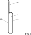
- Figure 4 shows in perspective a one-piece unit consisting of web 20 and bearing sleeve 14.
- the contour of the web 20 extends as an elongated projection 22 over the outer contour of the bearing sleeve 14, so that the bearing sleeve 14, as to Figure 3 described, is also held in the bearing shell 12 in a rotationally fixed manner by the recess 21 created by the bearing strip 11.
- the one-piece unit comprising web 20 and a tubular section 23 of the bearing sleeve 14 can preferably be manufactured from plastic by injection molding.
- the inner side of the web 20 terminates seamlessly with the inner side of the tubular section 23 of the bearing sleeve 14.
Landscapes
- Engineering & Computer Science (AREA)
- Mechanical Engineering (AREA)
- Hinges (AREA)
Applications Claiming Priority (1)
| Application Number | Priority Date | Filing Date | Title |
|---|---|---|---|
| DE102018209872.7A DE102018209872A1 (de) | 2018-06-19 | 2018-06-19 | Lagerung für einen Flügel an einem Rahmen |
Publications (2)
| Publication Number | Publication Date |
|---|---|
| EP3584396A1 EP3584396A1 (de) | 2019-12-25 |
| EP3584396B1 true EP3584396B1 (de) | 2025-03-26 |
Family
ID=66770261
Family Applications (1)
| Application Number | Title | Priority Date | Filing Date |
|---|---|---|---|
| EP19178269.7A Active EP3584396B1 (de) | 2018-06-19 | 2019-06-04 | Lagerung für einen flügel an einem rahmen |
Country Status (4)
| Country | Link |
|---|---|
| EP (1) | EP3584396B1 (pl) |
| DE (1) | DE102018209872A1 (pl) |
| ES (1) | ES3029639T3 (pl) |
| PL (1) | PL3584396T3 (pl) |
Families Citing this family (1)
| Publication number | Priority date | Publication date | Assignee | Title |
|---|---|---|---|---|
| EP4098832B1 (de) | 2021-06-02 | 2023-05-17 | Gretsch-Unitas GmbH Baubeschläge | Baugruppe zur anordnung an einer bandseite eines flügels eines fensters oder einer tür |
Family Cites Families (5)
| Publication number | Priority date | Publication date | Assignee | Title |
|---|---|---|---|---|
| DE3342842C2 (de) | 1983-11-26 | 1987-03-12 | Carl Fuhr Gmbh & Co, 5628 Heiligenhaus | Ecklager |
| FR2713270B1 (fr) * | 1993-12-01 | 1996-06-28 | Blocfer | Paumelle de vantail réglable. |
| EP1405975A1 (de) * | 2002-10-04 | 2004-04-07 | Steinbach & Vollmann GmbH & Co. KG | Einstellbare Türbandanordnung |
| ITUD20060059A1 (it) * | 2006-03-14 | 2007-09-15 | Otlav Spa | Cerniera per un serramento |
| DE102009026584A1 (de) | 2009-05-29 | 2010-12-16 | Aug. Winkhaus Gmbh & Co. Kg | Ecklager für einen gegen einen Rahmen schwenkbaren Flügel |
-
2018
- 2018-06-19 DE DE102018209872.7A patent/DE102018209872A1/de not_active Withdrawn
-
2019
- 2019-06-04 PL PL19178269.7T patent/PL3584396T3/pl unknown
- 2019-06-04 EP EP19178269.7A patent/EP3584396B1/de active Active
- 2019-06-04 ES ES19178269T patent/ES3029639T3/es active Active
Also Published As
| Publication number | Publication date |
|---|---|
| DE102018209872A1 (de) | 2019-12-19 |
| PL3584396T3 (pl) | 2025-06-09 |
| EP3584396A1 (de) | 2019-12-25 |
| ES3029639T3 (en) | 2025-06-24 |
Similar Documents
| Publication | Publication Date | Title |
|---|---|---|
| DE102007044637A1 (de) | Einstellbares Kofferraumdeckelscharnier | |
| EP1606485B1 (de) | Beschlag | |
| EP1707717A2 (de) | Vorreiberverschluss mit Selbstmontage | |
| EP2245252B1 (de) | Einstellbares ecklager für einen flügel eines fensters, einer tür oder dergleichen | |
| DE102010047774B4 (de) | Türscharnier | |
| EP3584396B1 (de) | Lagerung für einen flügel an einem rahmen | |
| DE19960432C2 (de) | Scharnier für eine Fahrzeugtür | |
| EP1881142B1 (de) | Scharnier | |
| EP4105416B1 (de) | Feststellvorrichtung für beidseitig angeschlagene tür | |
| EP2149664A2 (de) | Scharnierband mit einer Unterkonstruktion zur Befestigung an einem Türblatt | |
| DE102015013598A1 (de) | Toleranzausgleichselement und zugehörige Kraftfahrzeugkarosserie | |
| EP2148031B1 (de) | Türband sowie Tür | |
| EP1617025B1 (de) | Scharnier für stumpf einschlagende Türen | |
| WO1999046465A1 (de) | Höhenverstellbares gelenkband | |
| EP2740872B1 (de) | Zur verdeckten anordnung vorgesehenes ecklager | |
| EP2341206A2 (de) | Ecklager eines gegen einen Rahmen schwenkbaren Flügels eines Fensters und Fenster mit einem solchen Ecklager | |
| EP3278693B1 (de) | Beschlag für eine schiebetüre | |
| EP4108877B1 (de) | Scharnier für eine türe, ein fenster oder ein ähnliches bauteil | |
| EP2175096B1 (de) | Scharnier einer Verschlusseinrichtung, beispielsweise eines Fensters, einer Tür oder dergleichen, sowie Verschlusseinrichtung mit einem solchen Scharnier | |
| DE102006030783B4 (de) | Rahmenlose Trennwand, mit einem Oberlicht und mit einem justierbaren Montageprofil zur Montage an einer ortsfesten Zarge | |
| DE20105545U1 (de) | Band für Türen, Fenster o.dgl. | |
| EP1922467B1 (de) | Band für türen, fenster oder dergleichen | |
| EP1215356B1 (de) | Bandanordnung für Türen, Fenster und dergleichen | |
| DE29804967U1 (de) | Tür- oder Fensterband | |
| DE202007016708U1 (de) | Band für Türen, Fenster o.dgl. |
Legal Events
| Date | Code | Title | Description |
|---|---|---|---|
| PUAI | Public reference made under article 153(3) epc to a published international application that has entered the european phase |
Free format text: ORIGINAL CODE: 0009012 |
|
| STAA | Information on the status of an ep patent application or granted ep patent |
Free format text: STATUS: THE APPLICATION HAS BEEN PUBLISHED |
|
| AK | Designated contracting states |
Kind code of ref document: A1 Designated state(s): AL AT BE BG CH CY CZ DE DK EE ES FI FR GB GR HR HU IE IS IT LI LT LU LV MC MK MT NL NO PL PT RO RS SE SI SK SM TR |
|
| AX | Request for extension of the european patent |
Extension state: BA ME |
|
| STAA | Information on the status of an ep patent application or granted ep patent |
Free format text: STATUS: REQUEST FOR EXAMINATION WAS MADE |
|
| 17P | Request for examination filed |
Effective date: 20200526 |
|
| RBV | Designated contracting states (corrected) |
Designated state(s): AL AT BE BG CH CY CZ DE DK EE ES FI FR GB GR HR HU IE IS IT LI LT LU LV MC MK MT NL NO PL PT RO RS SE SI SK SM TR |
|
| P01 | Opt-out of the competence of the unified patent court (upc) registered |
Effective date: 20230517 |
|
| P03 | Opt-out of the competence of the unified patent court (upc) deleted | ||
| GRAP | Despatch of communication of intention to grant a patent |
Free format text: ORIGINAL CODE: EPIDOSNIGR1 |
|
| STAA | Information on the status of an ep patent application or granted ep patent |
Free format text: STATUS: GRANT OF PATENT IS INTENDED |
|
| RAP3 | Party data changed (applicant data changed or rights of an application transferred) |
Owner name: AUG. WINKHAUS SE & CO. KG |
|
| INTG | Intention to grant announced |
Effective date: 20241119 |
|
| GRAS | Grant fee paid |
Free format text: ORIGINAL CODE: EPIDOSNIGR3 |
|
| GRAA | (expected) grant |
Free format text: ORIGINAL CODE: 0009210 |
|
| STAA | Information on the status of an ep patent application or granted ep patent |
Free format text: STATUS: THE PATENT HAS BEEN GRANTED |
|
| AK | Designated contracting states |
Kind code of ref document: B1 Designated state(s): AL AT BE BG CH CY CZ DE DK EE ES FI FR GB GR HR HU IE IS IT LI LT LU LV MC MK MT NL NO PL PT RO RS SE SI SK SM TR |
|
| REG | Reference to a national code |
Ref country code: GB Ref legal event code: FG4D Free format text: NOT ENGLISH |
|
| REG | Reference to a national code |
Ref country code: CH Ref legal event code: EP |
|
| REG | Reference to a national code |
Ref country code: DE Ref legal event code: R096 Ref document number: 502019013096 Country of ref document: DE |
|
| REG | Reference to a national code |
Ref country code: IE Ref legal event code: FG4D Free format text: LANGUAGE OF EP DOCUMENT: GERMAN |
|
| REG | Reference to a national code |
Ref country code: NL Ref legal event code: FP |
|
| REG | Reference to a national code |
Ref country code: ES Ref legal event code: FG2A Ref document number: 3029639 Country of ref document: ES Kind code of ref document: T3 Effective date: 20250624 |
|
| PG25 | Lapsed in a contracting state [announced via postgrant information from national office to epo] |
Ref country code: RS Free format text: LAPSE BECAUSE OF FAILURE TO SUBMIT A TRANSLATION OF THE DESCRIPTION OR TO PAY THE FEE WITHIN THE PRESCRIBED TIME-LIMIT Effective date: 20250626 |
|
| PG25 | Lapsed in a contracting state [announced via postgrant information from national office to epo] |
Ref country code: FI Free format text: LAPSE BECAUSE OF FAILURE TO SUBMIT A TRANSLATION OF THE DESCRIPTION OR TO PAY THE FEE WITHIN THE PRESCRIBED TIME-LIMIT Effective date: 20250326 |
|
| PGFP | Annual fee paid to national office [announced via postgrant information from national office to epo] |
Ref country code: PL Payment date: 20250529 Year of fee payment: 7 Ref country code: DE Payment date: 20250618 Year of fee payment: 7 |
|
| REG | Reference to a national code |
Ref country code: LT Ref legal event code: MG9D |
|
| PG25 | Lapsed in a contracting state [announced via postgrant information from national office to epo] |
Ref country code: NO Free format text: LAPSE BECAUSE OF FAILURE TO SUBMIT A TRANSLATION OF THE DESCRIPTION OR TO PAY THE FEE WITHIN THE PRESCRIBED TIME-LIMIT Effective date: 20250626 |
|
| PGFP | Annual fee paid to national office [announced via postgrant information from national office to epo] |
Ref country code: NL Payment date: 20250618 Year of fee payment: 7 Ref country code: BE Payment date: 20250617 Year of fee payment: 7 |
|
| PG25 | Lapsed in a contracting state [announced via postgrant information from national office to epo] |
Ref country code: HR Free format text: LAPSE BECAUSE OF FAILURE TO SUBMIT A TRANSLATION OF THE DESCRIPTION OR TO PAY THE FEE WITHIN THE PRESCRIBED TIME-LIMIT Effective date: 20250326 |
|
| PG25 | Lapsed in a contracting state [announced via postgrant information from national office to epo] |
Ref country code: LV Free format text: LAPSE BECAUSE OF FAILURE TO SUBMIT A TRANSLATION OF THE DESCRIPTION OR TO PAY THE FEE WITHIN THE PRESCRIBED TIME-LIMIT Effective date: 20250326 |
|
| PGFP | Annual fee paid to national office [announced via postgrant information from national office to epo] |
Ref country code: FR Payment date: 20250618 Year of fee payment: 7 |
|
| PG25 | Lapsed in a contracting state [announced via postgrant information from national office to epo] |
Ref country code: GR Free format text: LAPSE BECAUSE OF FAILURE TO SUBMIT A TRANSLATION OF THE DESCRIPTION OR TO PAY THE FEE WITHIN THE PRESCRIBED TIME-LIMIT Effective date: 20250627 Ref country code: BG Free format text: LAPSE BECAUSE OF FAILURE TO SUBMIT A TRANSLATION OF THE DESCRIPTION OR TO PAY THE FEE WITHIN THE PRESCRIBED TIME-LIMIT Effective date: 20250326 |
|
| PGFP | Annual fee paid to national office [announced via postgrant information from national office to epo] |
Ref country code: AT Payment date: 20250616 Year of fee payment: 7 |
|
| PGFP | Annual fee paid to national office [announced via postgrant information from national office to epo] |
Ref country code: TR Payment date: 20250613 Year of fee payment: 7 |
|
| REG | Reference to a national code |
Ref country code: DE Ref legal event code: R081 Ref document number: 502019013096 Country of ref document: DE Owner name: AUG. WINKHAUS SE, DE Free format text: FORMER OWNER: AUG. WINKHAUS SE & CO. KG, 48291 TELGTE, DE |
|
| PG25 | Lapsed in a contracting state [announced via postgrant information from national office to epo] |
Ref country code: SE Free format text: LAPSE BECAUSE OF FAILURE TO SUBMIT A TRANSLATION OF THE DESCRIPTION OR TO PAY THE FEE WITHIN THE PRESCRIBED TIME-LIMIT Effective date: 20250326 |
|
| PG25 | Lapsed in a contracting state [announced via postgrant information from national office to epo] |
Ref country code: SM Free format text: LAPSE BECAUSE OF FAILURE TO SUBMIT A TRANSLATION OF THE DESCRIPTION OR TO PAY THE FEE WITHIN THE PRESCRIBED TIME-LIMIT Effective date: 20250326 |
|
| RAP2 | Party data changed (patent owner data changed or rights of a patent transferred) |
Owner name: AUG. WINKHAUS SE |
|
| PG25 | Lapsed in a contracting state [announced via postgrant information from national office to epo] |
Ref country code: PT Free format text: LAPSE BECAUSE OF FAILURE TO SUBMIT A TRANSLATION OF THE DESCRIPTION OR TO PAY THE FEE WITHIN THE PRESCRIBED TIME-LIMIT Effective date: 20250728 |
|
| PGFP | Annual fee paid to national office [announced via postgrant information from national office to epo] |
Ref country code: ES Payment date: 20250718 Year of fee payment: 7 |
|
| PGFP | Annual fee paid to national office [announced via postgrant information from national office to epo] |
Ref country code: IT Payment date: 20250702 Year of fee payment: 7 |
|
| PG25 | Lapsed in a contracting state [announced via postgrant information from national office to epo] |
Ref country code: EE Free format text: LAPSE BECAUSE OF FAILURE TO SUBMIT A TRANSLATION OF THE DESCRIPTION OR TO PAY THE FEE WITHIN THE PRESCRIBED TIME-LIMIT Effective date: 20250326 |
|
| PG25 | Lapsed in a contracting state [announced via postgrant information from national office to epo] |
Ref country code: RO Free format text: LAPSE BECAUSE OF FAILURE TO SUBMIT A TRANSLATION OF THE DESCRIPTION OR TO PAY THE FEE WITHIN THE PRESCRIBED TIME-LIMIT Effective date: 20250326 |
|
| PG25 | Lapsed in a contracting state [announced via postgrant information from national office to epo] |
Ref country code: SK Free format text: LAPSE BECAUSE OF FAILURE TO SUBMIT A TRANSLATION OF THE DESCRIPTION OR TO PAY THE FEE WITHIN THE PRESCRIBED TIME-LIMIT Effective date: 20250326 |
|
| PG25 | Lapsed in a contracting state [announced via postgrant information from national office to epo] |
Ref country code: IS Free format text: LAPSE BECAUSE OF FAILURE TO SUBMIT A TRANSLATION OF THE DESCRIPTION OR TO PAY THE FEE WITHIN THE PRESCRIBED TIME-LIMIT Effective date: 20250726 |
|
| PG25 | Lapsed in a contracting state [announced via postgrant information from national office to epo] |
Ref country code: DK Free format text: LAPSE BECAUSE OF FAILURE TO SUBMIT A TRANSLATION OF THE DESCRIPTION OR TO PAY THE FEE WITHIN THE PRESCRIBED TIME-LIMIT Effective date: 20250326 |
|
| PG25 | Lapsed in a contracting state [announced via postgrant information from national office to epo] |
Ref country code: CZ Free format text: LAPSE BECAUSE OF FAILURE TO SUBMIT A TRANSLATION OF THE DESCRIPTION OR TO PAY THE FEE WITHIN THE PRESCRIBED TIME-LIMIT Effective date: 20250326 |
|
| REG | Reference to a national code |
Ref country code: CH Ref legal event code: H13 Free format text: ST27 STATUS EVENT CODE: U-0-0-H10-H13 (AS PROVIDED BY THE NATIONAL OFFICE) Effective date: 20260127 |
|
| PG25 | Lapsed in a contracting state [announced via postgrant information from national office to epo] |
Ref country code: MC Free format text: LAPSE BECAUSE OF FAILURE TO SUBMIT A TRANSLATION OF THE DESCRIPTION OR TO PAY THE FEE WITHIN THE PRESCRIBED TIME-LIMIT Effective date: 20250326 |
|
| PLBE | No opposition filed within time limit |
Free format text: ORIGINAL CODE: 0009261 |
|
| STAA | Information on the status of an ep patent application or granted ep patent |
Free format text: STATUS: NO OPPOSITION FILED WITHIN TIME LIMIT |
|
| REG | Reference to a national code |
Ref country code: CH Ref legal event code: L10 Free format text: ST27 STATUS EVENT CODE: U-0-0-L10-L00 (AS PROVIDED BY THE NATIONAL OFFICE) Effective date: 20260211 |