EP3584047B1 - Fräsmaschine für kantenanleimstruktur und kantenanleimsverfahren - Google Patents
Fräsmaschine für kantenanleimstruktur und kantenanleimsverfahren Download PDFInfo
- Publication number
- EP3584047B1 EP3584047B1 EP19181551.3A EP19181551A EP3584047B1 EP 3584047 B1 EP3584047 B1 EP 3584047B1 EP 19181551 A EP19181551 A EP 19181551A EP 3584047 B1 EP3584047 B1 EP 3584047B1
- Authority
- EP
- European Patent Office
- Prior art keywords
- milling
- edge
- panel
- along
- milling tool
- Prior art date
- Legal status (The legal status is an assumption and is not a legal conclusion. Google has not performed a legal analysis and makes no representation as to the accuracy of the status listed.)
- Active
Links
Images


Classifications
-
- B—PERFORMING OPERATIONS; TRANSPORTING
- B27—WORKING OR PRESERVING WOOD OR SIMILAR MATERIAL; NAILING OR STAPLING MACHINES IN GENERAL
- B27D—WORKING VENEER OR PLYWOOD
- B27D5/00—Other working of veneer or plywood specially adapted to veneer or plywood
- B27D5/006—Trimming, chamfering or bevelling edgings, e.g. lists
Definitions
- the present invention relates to a milling device for edge-banding machine according to the preamble of claim 1, an edge-banding machine provided with said milling device and a method for edge-banding by means of said edge-banding machine.
- a milling device is known from the document EP 1 302 287 A2 .
- the milling device of the invention is intended to be advantageously used in edge-banding machines designed to carry out the application of cladding edges on panels made of different materials such as wood, chipboard, plywood, MDF, etc.
- the milling device in question is intended to be used to carry out the end milling of the cladding edges by linearly cutting the ends of such edges, and/or to carry out the rounding of the cladding edges performing an angular machining for joining and rounding at the ends of the cladding edges to seamlessly join the orthogonal faces of the panels.
- the milling device of the invention is advantageously applicable to edge-banding machines of the unilateral type, which are adapted to apply a cladding edge to one side of the panel at each passage of the panel through the edge-banding machine.
- edge-banding machines have been introduced on the market which are adapted to apply the cladding edges on the sides of the panels and are provided with operating units adapted to perform the necessary finishing operations of the same edges.
- edge-banding machines of the unilateral type which are adapted to apply an edge to one side of the panel at each passage of the panel through the edge-banding machine.
- edge-banding machines of the known type comprise a support frame provided with a sliding guide extending between an inlet port and an outlet port, and driving means (obtained for example with a sliding belt) adapted to move the panels to advance along the sliding guide from the inlet port to the outlet port.
- the edge-banding machine further comprises a storage station adapted to accommodate an edging tape to be applied to the panels and which will form the cladding edge. More specifically, such storage station comprises a rotatable support which carries the wrapped edging tape and is operable to rotate to unwrap the edging tape along the sliding lane to apply the edging tape to the side of the panel.
- the edge-banding machine also comprises a gluing unit able to deposit a layer of glue (for example of the heat-meltable type) on the side of the panel and to compress, by means of two or more rollers, the edging tape to the layer of glue to glue the tape to the side of the panel.
- the gluing unit is provided with a cutting tool able to cut off the edging tape at the rear end of the panel.
- the edging tape glued to the panel using the above gluing unit has a greater length than the panel and a greater width than the thickness of the same panel, so that the edging tape protrudes with respect to the ends and the longitudinal sides of the side of the panel.
- the edge-banding machine further comprises an end milling unit arranged downstream of the gluing unit and provided with a circular saw adapted to cut the portions of the edging tape that protrude beyond the ends of the side of the panel, linearly cutting the edging tape ends substantially flush with the ends of the side of the panel.
- the edge-banding machine also comprises a trimming unit arranged downstream of the end milling unit and adapted to cut the portions of the edging tape that protrude beyond the longitudinal sides of the side of the panel.
- the edge-banding machine also comprises a rounding unit positioned downstream of the trimming unit and provided with a milling tool able to round off the ends of the edging tape to seamlessly join the outer surface of the edging tape with the adjacent orthogonal side of the panel.
- the milling tool of the rounding unit is provided peripherally with multiple cutting teeth, each of which has an arched profile with radius of curvature equal to the thickness of the edging tape to correctly join the two faces at 90 degree of the panel.
- the milling device of the rounding unit is able to pursue the panels during the translation run along the sliding lane to realize the angular rounding of the corners of the cladding edges at the ends of the panels that advance.
- the milling device comprises a front coupler and a transverse coupler able to rest on the panel during the milling operations.
- the milling device comprises two screw adjustment devices connected to the corresponding couplers and able to be operated by the user to set the position of the couplers with respect to the milling device in order to adjust the position of the milling device from the panel, for example according to the thickness of the cladding edge.
- a first drawback of the aforesaid known edge-banding machines is that they necessarily comprise two distinct operating units (the end milling unit and the rounding unit) to machine the ends of the edges during the different passages of the panel in the edge-banding machine, with consequent high cost and considerable size of the edge-banding machines.
- an edge-banding machine has been introduced into the market which comprises a milling device able to carry out both the end milling operations and the rounding operations, and described for example in patent application EP 3248745 A1 .
- this milling device comprises a milling tool whose cutting profile is provided with a rear rounding segment, with arched shape, and with a front end milling segment with rectilinear shape.
- the milling tool can be actuated to move horizontally, along its rotation axis, between a retracted position, in which the end milling segment is able to act on the cladding edge to cut it linearly, and a forward position, in which the rounding segment is able to act on the cladding edge to round it off.
- the rectilinear end milling segment is the milling tool is lowered (for example by one or two tenths of a millimeter) relative to the rounding segment, so that, when the milling tool is brought to a forward position to round off the cladding edge, the front end milling segment does not come in contact with the adjacent faces of the panel to avoiding ruining them.
- This configuration entails that, when the milling tool is in the retracted position, the end milling segment is at a slightly lower position than that of the face of the panel, producing on the cladding edge a step (of approximately one or two tenths of a millimeter) that is raised with respect to the face of the panel, determining a slight discontinuity that can be perceived by touch.
- the problem at the basis of the present invention therefore is to overcome the drawbacks exhibited by known solutions, making available a milling device for edge-banding machine, which is able to carry out, in a qualitatively improved manner, multiple different machining operations on the cladding edges applied to the panel (for example end milling and rounding).
- Another object of the present invention is to provide a milling device for an edge-banding machine which is constructively simple and cost-effective to implement.
- Another object of the present invention is to provide a milling device for an edge-banding machine which is operatively safe and reliable.
- Another object of the present invention is to provide a milling device for edge-banding machine that is easy to use.
- reference numeral 1 indicates as a whole a milling device object of the present invention.
- the milling device 1 of the invention is intended to be advantageously mounted on an edge-banding machine 100 adapted to carry out the application of cladding edges on panels made, for example, of wood, chipboard, plywood, MDF (Medium-density fiberboard), etc.
- the milling device 1 is intended to execute on the cladding edges of the panels rounding operations, or end milling operations, or (with reference to the particular example illustrated below) both of the aforesaid operations.
- each panel P is substantially parallelepiped shape and it is provided with two main faces FP, generally cladded, mutually parallel and opposite and mutually connected perimetrically by four sides L parallel two by two which define the thickness of the panel P.
- Each side L of panel P extends longitudinally between a front end edge and a rear end edge and is delimited in width by two longitudinal sides preferably parallel to each other.
- the edge-banding machine 100 is adapted to apply a cladding edge B (e.g. PVC, ABS, melamine, wood, Formica, aluminum, etc.) on one or more sides L of panel P.
- a cladding edge B e.g. PVC, ABS, melamine, wood, Formica, aluminum, etc.
- the edge-banding machine 100 is in particular of the unilateral type, being adapted to apply a cladding edge B to one side only of panel P at every passage of panel P through the edge-banding machine 100 itself.
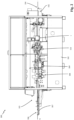
- the edge-banding machine 100 comprises a supporting frame 101 intended to rest on the ground and provided with a sliding lane 102 extending between an inlet port 103 and an outlet port 104, preferably according to a substantially rectilinear and in particular horizontal sliding direction S.
- the edge-banding machine 100 further comprises feeding means 105 adapted to move panels P to advance along the sliding lane 102 from the inlet port 103 to the outlet port 104.
- the feeding means 105 comprise a track conveyor belt of conventional type per se, adapted to advance panels P individually and horizontally, in succession to each other from the inlet port 103 to the outlet port 104.
- the edge-banding machine also comprises a storage station 106 adapted to accommodate an edging tape to be applied to sides L of panels P and that will form the cladding edge B of panels P themselves. More specifically, such storage station 106 comprises a rotatable support 107 which carries the wrapped edging tape (not shown) and is operable to rotate to unwrap the edging tape along the sliding lane 102 to apply the edging tape to side L of panel P.
- the edge-banding machine 100 advantageously comprises a grinding unit 108, of known type per se, placed along the sliding lane 102 downstream of the inlet port 103 and provided with one or more cutters (not shown) adapted to act on side L of panel P to eliminate the irregularities thereof.
- the edge-banding machine 100 preferably comprises a gluing unit 109 placed downstream of the grinding unit 108 and comprising, in a conventional manner per se, a distribution device adapted to take an adhesive (such as heat-melting) from a containment tank and deposit a layer of such an adhesive on side L of panel P.
- the gluing unit 109 is also provided with two or more rollers adapted to compress the edging tape to the layer of glue to glue the edging tape to side L of panel P.
- the gluing unit 109 is also provided with a cutting tool adapted to cut the edging tape at the rear edge of side L of panel P, so that the portion of edging tape glued to side L of panel P forms a cladding edge B of panel P itself.
- the cladding edge B glued to the corresponding side L of panel P by the gluing unit 109 has a greater length than side L of panel P and greater width than the thickness of panel P itself, so that the cladding edge B protrudes with respect to the end edges and the sides of side L of panel P.
- the edge-banding machine 100 also comprises a trimming unit 110, known in itself, positioned downstream of the gluing unit 109 and able to cut the portions of the cladding edge B that project beyond the flanks of the side L of the panel P substantially flush with the main faces FP of the panel P itself.
- a trimming unit 110 known in itself, positioned downstream of the gluing unit 109 and able to cut the portions of the cladding edge B that project beyond the flanks of the side L of the panel P substantially flush with the main faces FP of the panel P itself.
- the edge-banding machine 100 may advantageously be provided with further operating units of known type per se and not described in the present description.
- the edge-banding machine 00 comprises a control unit 100, in particular provided with a PLC, adapted to control in an automated or semi-automated manner the operating units 108, 109, 110 of the edge-banding machine 100 itself.
- the milling device 1 of the present invention is intended to be mounted on the support frame 101 of the edge-banding machine 100, along the sliding lane 102 preferably downstream of the gluing unit 109 and in particular downstream of the trimming unit 110 as well.
- Such a milling device 1 can be operated for milling the portions of the cladding edge B that protrude beyond the end edges of the corresponding side L of panel P, defining two ends E of the cladding edge B substantially aligned with the edges of the corresponding side L of panel P.
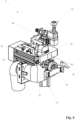
- the milling device comprises a support structure 2 intended to be mounted on the edge-banding machine 100, and in particular intended to be fixed to the support frame 101 of the edge-banding machine 100.
- the milling device 1 also comprises a milling head 3 provided with a milling frame 4, which is mounted on the support structure 2 and is provided with an operating zone 5 in which the coating edge B of the panel P that advances along the sliding lane 102 is susceptible of passing.
- the milling device 1 comprises a single milling head 3.
- the milling device 1 further comprises a milling tool 6 rotatably mounted on the milling frame 4 of the milling head 3 and provided with a rotation axis X, preferably orthogonal to the sliding direction S of the panels P and in particular horizontal.
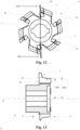
- the milling tool 6 is perimetrically provided with a cutting profile 7 extending around the rotation axis X and intended to act at the operating zone 5 to mill the cladding edge B of the panel P.
- the milling tool 6 extends advantageously according to the rotation axis X between a front side 8 and a rear side 9, between which the cutting profile 7 develops in section.
- the milling tool 6 is peripherally provided with a plurality of teeth 10 arranged around the rotation axis X and on which the aforesaid cutting profile 7 is obtained.
- the milling tool 6 consists of a rotating body made of rigid material, preferably metallic, such as steel (for example, super high speed steel), sintered metal, etc.
- the milling device 1 also comprises actuation means 11 mechanically connected to the milling device 6 and able to bring the milling device in rotation around the rotation axis X to allow the cutting profile 7 of the milling tool 6 to mill the cladding edge B of the panel B.
- the actuation means 11 comprise a first motor, preferably electric, mounted on the milling frame 4 of the milling head 3 and provided with an output shaft to which the milling tool 6 is connected to make the milling tool rotate around the rotation axis X, at a speed for example of 12000 rotations/minute.
- the support structure 2 of the milling device 1 comprises a translation guide 12 orthogonal to the rotation axis X of the milling tool 6 and intended to be positioned parallel to the sliding direction S of the sliding lane 102 along which the panels P to be banded.
- the milling device 1 advantageously comprises a movable carriage 13 slidably mounted on the translation guide 12 and bearing mounted the milling frame 4 of the milling head 3.
- the movable carriage 13 can be actuated to slide along the translation guide 12 to allow the milling head 3 to follow the panels that advance on the sliding lane 102.
- the milling device 1 advantageously comprises displacement means (not shown in the accompanying figures), which are mounted on the support structure 2 and are mechanically connected to the movable carriage 13 to actuate the carriage to slide along the translation guide 12.
- the milling frame 4 of the milling head 3 is rotatably mounted on the support structure 2 around an overturning axis Y preferably orthogonal with respect to the translation guide 12 and parallel to the rotation axis X of the milling tool 6.
- the milling frame 4 is rotatably mounted on the movable carriage 13 of the milling device 1, preferably by means of an overturning shaft 14 coaxial to the overturning axis Y.
- the milling device 1 comprises movement means 15 mechanically connected to the milling frame 4 of the milling head 3 to drive the latter to rotate around the overturning axis Y for at least one rotation run between at least two working positions illustrated in figures 4 and 5 .
- the movement means 15 (able to drive the rotation of the milling head 3 around the overturning axis Y) comprise a second motor 16 integral with the movable carriage 13, mechanically connected to the milling frame 4 of the milling head 3 to drive the milling frame to rotate around the overturning shaft 14, and advantageously coupled with the movement means to synchronize the rotation of the milling head 3 around the overturning axis Y with its translation along the translation guide 12 above the movable carriage 13.
- the aforesaid movement means comprise a transmission chain connected to the movable carriage 13 and engaged to a pinion moved by the second motor 16 so that, when the latter is activated to make the milling head 3 rotate around the overturning axis Y, the transmission chain, as a result of the movement of the aforesaid pinion, allows to displace, concurrently and in a synchronized manner, the movable carriage 13 along the translation guide 12.
- the milling frame 4 of the milling head 3 defines an operating side 17 parallel to the rotation axis X of the milling tool 6 and, preferably, parallel to the overturning axis Y of the milling frame 4.
- Said operating side 17 passes through the operating zone 5 and is intercepted by the milling tool 6 so that the portion of the cutting profile 7 thereof, which faces said operating side 17, acts on the cladding edge B of the panel P to mill it.
- the teeth 10 of the milling tool 6 are brought in sequence on the operative side 17 of the milling head 3 to act, with its corresponding portion of the cutting profile 7, on the cladding edge B of the panel P that passes through the operating zone 5 of the milling head 3.
- the movement means 15 are able to drive the rotation of the milling frame 4 around the overturning axis Y to bring the operating side 17 of the milling head 3 at the part of the cladding edge B to be milled, so that the cutting profile 7 of the milling tool 6 acts on the cladding edge B only at said operating side 17.
- the cutting profile 7 of the milling tool 6 is provided with a section having multiple operating segments 18, 19, each able to apply a different machining process to the cladding edge B to cut the latter according to a corresponding shape.
- the aforesaid section of the cutting profile 7 is defined on a section plane radial and parallel to the rotation axis X and containing in particular the rotation axis X.
- the section of the cutting profile 7 is provided with a first operating section 18 placed in a first radial position with respect to the rotation axis X, and with a second operating section 19 with shape different from the first operating section 18 and placed in a second radial position with respect to said rotation axis X different from the aforesaid first radial position of the first operating section 18.
- the first operating section 18 has rectilinear shape to cut linearly the cladding edge B, extending preferably between the front side 8 of the milling tool 6 and the second operating section 19.
- the first operating section 18, rectilinear is substantially parallel to the rotation axis X (in particular with an inclination between 0° and 2°, for example approximately 1°) in order to execute an end milling operation to cut an end E of the cladding edge flush with the end corners of the corresponding side L of the panel P itself (as illustrated in the example of figure 16 ).
- the second operating section 19 has arched shape, with concavity oriented towards the front side 8 of the milling tool 6 and able to execute a rounding operation to round off the ends E of the cladding edge B of the panel P, so as to seamlessly join the outer surface of said cladding edge B with the outer surface of the adjacent side L of the panel P or with the outer surface of the cladding edge B applied to said adjacent side L (as illustrated in the example of figure 17 ).
- the cutting profile 7 of the milling tool 6 may comprise operating sections with different configurations from those of the example illustrated above: for example, the cutting profile 7 may comprise two operating sections with arched shape with different radii of curvature to apply different corner rounding to the cladding edges B, or two operating sections with rectilinear shape and with different inclinations with respect to the rotation axis X (for example of 1° and 30°) to cut linearly the cladding edges B with different inclinations. Moreover, the cutting profile 7 of the milling tool 6 may also comprise more than two operating sections placed in corresponding radial positions with respect to the rotation axis X.
- each operating section 18, 19 of the cutting profile 7 is defined by the radial distance DR1, DR2 of the operating section 18, 19 from the rotation axis X along a direction developing radially from said rotation axis X and lying on the radial section plane that defines the corresponding section of the cutting profile 7.
- each operating section 18, 19 is determined starting from a reference point of the corresponding operating section 18, 19 given for example by an end point thereof (as indicated in the example of figure 13 ).
- the milling device 1 comprises first actuator means 20 mechanically connected to the milling tool 6 and able to displace the latter along its rotation axis X between multiple operating positions to bring the corresponding operating sections 18, 19 of the cutting profile 7 at the operating zone 5 of the milling head 3.
- the first actuator means 20 are able to displace the milling tool 6 between a first operating position and a second operating position.
- the first operating position the first operating section 18 of the cutting profile 7 of the milling tool 6 is placed in the operating zone 5 to act on the cladding edge B of the panel P for the purpose, for example, of linearly cutting the end E of the cladding edge B (as illustrated in the example of figures 14 and 16 ).
- the second operating section 19 of the cutting profile 7 of the milling tool 6 is placed in the operating zone 5 to act on the cladding edge B of said panel P for the purpose, for example, of rounding off the end E of said cladding edge B (as illustrated in the example of figures 15 and 17 ).
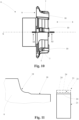
- the milling device 1 comprises a transverse coupler 21 and, advantageously, a front coupler 22, able to maintain the milling tool 6, during the milling of the cladding edges B of the panel P, constantly in a determined position with respect to the cladding edge B to assure consistent machining thereon.
- the transverse coupler 21 is mounted on the milling frame 4 of the milling head 3 and it can be moved, with relative motion with respect to the milling tool 6, along an adjustment direction R1 orthogonal to the rotation axis X and, preferably, orthogonal to the operating side 17 of the milling head 3.
- the transverse coupler 21 is provided with a coupling surface 23 having at least one contact zone 24, which is substantially orthogonal to the adjustment direction R and is adapted to abut against at least one adjacent surface of the panel parallel to the rotation axis X in order to define, along said adjustment direction R, a working height at which the milling tool 6 acts on the cladding edge B.
- said working height coincides, at each instant of the machining of the cladding edge B, with the position, along the adjustment direction R1, of the adjacent surface of the panel P whereon, at that instant, abuts the contact zone 24 of the transverse coupler 21.
- the contact zone 24 of the coupling surface 23 of the transverse coupler 21 faces the operating side 17 of the milling head 3 and it is preferably parallel to the rotation axis X of the milling tool 6 and in particular to the overturning axis Y of the milling frame 4.
- the contact zone 24 of the transverse coupler 21 abuts in succession on the adjacent surfaces of the panel P parallel to the rotation axis X, consisting in particular of the main faces FP of the panel P, or of the surface of the side L of the panel P adjacent to the end edge of the panel P whereat the milling head 3 is operating, or of the surface of the cladding edge B applied to said adjacent side L.
- the transverse coupler 21 maintains the milling tool 6 in the same position, along the adjustment direction R1, with respect to the cladding edge B to execute a correct machining operating thereon.
- the transverse coupler 21 comprises a slidable frame 25, which is slidably constrained to the milling frame 4, and a coupling element 26 mounted on the slidable frame 25 and provided with the aforesaid coupling surface 23.
- the coupling element 26 comprises a rotating disc, hinged in an idle manner on the slidable frame 25 with the revolution axis parallel to the rotation axis X of the milling tool 6.
- Said rotating disc is provided with an annular surface that extends around the revolution axis and that defines the coupling surface 23 of the transverse coupler 21, whose contact zone 24 is given by the section of the annular surface that faces the operating side 17 of the milling head 3 and that is intended to abut on the panel P.
- the rotating disc slides on the adjacent surface of the panel P going in contact on said adjacent surface with the section of the annular surface that, as a result of the rotation of the rotating disc, reaches instant by instant the operating side 17.
- the transverse coupler 21 may not be of the rotary type, comprising for example a slide of non-stick material fixed on the slidable frame 25 and able to slide on the adjacent surface of the panel P.
- the transverse coupler 21 (and in particular the coupling element 26 thereof) is positioned in front of the forward side 8 of the milling tool 6.
- the milling device 1 comprises second actuator means 27 mechanically connected to the transverse coupler 21 and configured to displace the latter along the adjustment direction R1 selectively in multiple reference positions (associated with corresponding operating positions of the milling tool 6), able to define corresponding positions, along the adjustment direction R1, of the milling tool 6 with respect to the cladding edge B during the milling operations thereof.
- the second actuator means 27 are able to selectively displace the transverse coupler 21 in a first reference position, when the milling tool 6 is brought by the first actuator means 20 in the aforesaid first operating position, and a second reference position, when the milling tool 6 is brought to the second operating position.
- the contact zone 24 of its coupling surface 23 is arranged (on the operating side 17) in the first radial position of the first operating section 18 of the cutting profile 7 of the milling tool 6 with respect to the rotation axis X thereof, so as to position said first operating section 18 at the aforesaid work height during the machining of the cladding edge B (as illustrated in the examples of figures 14 and 16 ).
- the contact zone 24 of its coupling surface 23 is arranged (on the operating side 17) in the second radial position of the second operating section 19 of the cutting profile 7 of the milling tool 6, so as to position said second operating section 19 at the aforesaid work height during the machining of the cladding edge B (as illustrated in the examples of figures 15 and 17 ).
- the contact zone 24 of the transverse coupler 21 is arranged in the first radial position at the same distance from the rotation axis X of the milling tool 6 of the first operating section 18, so that the latter, during the machining of the cladding edge B, cuts the end E of the cladding edge B flush with the end corners of the corresponding side L of the panel P (with a precision of less than one tenth of a millimeter).
- the contact zone 24 of the transverse coupler 21 is arranged in the second radial position of said second operating section 19 at a greater distance from the rotation axis X than the first radial position of the first operating section 18, so that, during the machining of the cladding edge B, the second (arched) operating section 19 mills the cladding edge B seamlessly joining the outer surface of the edging tape B with the adjacent surface of the adjacent side L of the panel P, and at the same time, the first operating section 18 remains separate from said adjacent surface in order not to damage it.
- the milling device 1 comprises a support 28 fixed to the overturning shaft 14 and provided with a coupling guide 29, orthogonal to the overturning shaft 14 and to the translation guide 12 and parallel to the adjustment direction R1, on which coupling guide 29 the milling frame 4 of the milling head 3 is slidably mounted.
- the milling device comprises a pusher means 30, obtained advantageously with a pneumatic piston, which is mounted on the support 28 and is driven by the control unit to displace the milling frame 4 of the milling head 3 along the coupling guide 29 until the transverse coupler 21 is pushed to abut on the panel P.
- the milling frame 4 of the milling head 3 comprises a support body 31 mechanically connected to the support structure 2 of the milling device 1 and provided with a positioning guide substantially rectilinear and parallel to the rotation axis X of the milling tool 6.
- the support body 31 of the milling head 3 is slidably mounted on the coupling guide 29 of support 28 of the milling device 1.
- the milling frame 4 comprises a displacement body 32 slidably constrained to the positioning guide of the support body 31 and carrying rotatably mounted the milling tool 6 around the rotation axis X.
- the aforesaid displacement body 32 bears mounted the transverse coupler 21 and preferably the front coupler 22 and the first motor of the actuation means 11 able to set the milling tool 6 in rotation.
- the first actuator means 20 of the milling device 1 are connected to the displacement body 32 and are provided to displace the latter along the positioning guide of the supporting body 31 to move the milling tool 6 between the first operating position and the second operating position along the rotation axis X.
- the first actuator means 20 comprise a linear displacement actuator, in particular of the pneumatic type, mounted on the support body 31 of the milling frame 4 and connected to the displacement body 32 to move the latter along the positioning guide.
- a linear displacement actuator in particular of the pneumatic type
- the first actuator means 20 are arranged for moving, along the rotation axis X, the support structure 2 of the milling device 1 or the support 28 of the milling head 3, in both cases for the purpose of displacing the milling tool 6 between the first operating position and the second operating position.
- the second actuator means 27 are mechanically connected to the slidable frame 25 of the transverse coupler 21 and are arranged for moving said slidable frame 25 along the adjustment direction R1 in order to move the transverse coupler 21 between the first reference position and the second reference position.
- the slidable frame 25 of the transverse coupler 21 is constrained to the milling frame 4, and in particular to the displacement body 32 thereof, by means of one or more guides 33 parallel to the adjustment direction R1.
- the slidable frame 25 comprises two lateral arms 34, parallel to each other and to the adjustment direction R1, which delimit between them a passage 35 traversed by the replacement body 32 and by the milling tool.
- the lateral arms 34 are substantially L shaped and they are each provided with a base segment 34' that terminates with a corresponding front end 36, and with a rear segment 34" which develops from the corresponding base segment 34' and terminates with an apical end 38.
- the slidable frame 25 also comprises a first crosspiece 37, which is positioned to connect the front ends 36 of the lateral arms 34, is arranged ahead of the front side 8 of the milling tool 6 and it bears mounted the coupling element 26.
- the slidable frame 25 comprises second crosspiece 39 positioned to connect the apical ends 38 of the lateral arms 34 and substantially orthogonal to the adjustment direction R1.
- the guides 33 of the slidable frame 25 are obtained with one or more elongated slots 40, which are obtained on the lateral arms 34 of the slidable frame 25 and they have longitudinal development parallel to the adjustment direction R1.
- a corresponding guiding screw 41 which is fastened to the displacement body 32 of the milling frame 4 and with respect to which the elongated slot 40 can slide to allow the displacement of the slidable frame 25 of the transverse coupler 21 along the adjustment direction R1.
- the second actuator means 27 comprise at least one linear actuator 42, preferably of the pneumatic type, having movement axis S parallel to the adjustment direction R1.
- the linear actuator 42 is mechanically connected to the slidable frame 25 of the transverse coupler 21 to move the latter along the adjustment direction R1.
- the linear actuator 42 is mounted on the slidable frame 25 of the transverse coupler 21 and, in particular, on a third crosspiece 43 positioned to connect the base segments 34' of the lateral arms 34.
- the linear actuator 42 is also connected to the milling frame 4 and in particular to the displacement body 32 thereof.
- the linear actuator 42 is provided with a jacket 44 fixed to the slidable frame 25 of the transverse coupler 21, and with a movable member 45 fixed to the displacement body 32 of the milling frame 4 and able to be actuated to be displaced, with respect to the jacket 44, along the movement axis S so as to move the jacket 44 (and hence the slidable frame 25 of the transverse coupler 21) with respect to the displacement body 32.
- the transverse coupler 21 is fixed with respect to the milling frame 4 (or to the displacement body 32 thereof) and the milling frame 6 is moved by the first actuator means 20 to be displaced, along the adjustment direction R1, with respect to the transverse coupler 21 to define the reference positions thereof.
- the transverse coupler 21 is provided with a first end stop portion 46, which abuts against the milling frame 4 (and in particular the displacement body 32) when the transverse coupler 21 is in the first reference position, and with a second end stop portion 47, which abuts with the milling frame 4 (and in particular the displacement body 32) when the transverse coupler 21 is in the second reference position.
- first end stop portion 46 and the second end stop portion 47 are arranged on the slidable frame 25 of the transverse coupler 21.
- the milling frame 4 (and in particular the displacement body 32) is provided with a first abutment portion 48 and with a second abutment portion 49 intended to receive in abutment, respectively, the first end stop portion 46 and the second end stop portion 47 of the transverse coupler 21.
- the second actuator means 27 are able to displace the slidable frame 25 of the transverse coupler 21 along the adjustment direction R1 according to a first direction of displacement, until the first end stop portion 46 abuts against the first abutment portion 48 of the milling frame 4, determining the first reference position of the transverse coupler 21.
- the second actuator means 27 are able to displace the slidable frame 25 of the transverse coupler 21 along the adjustment direction R1 according to a second direction of displacement (opposite the first), until the second end stop portion 47 abuts against the first abutment portion 49 of the milling frame 4, determining the first reference position of the transverse coupler 21.
- the milling head comprises adjustment means 50, preferably mounted on the slidable frame 25, mechanically connected to the end stop portions 46, 47 of the transverse coupler 21 and arranged for varying the relative distance of the first end stop portion 46 with respect to the second end stop portion 47 along the adjustment direction R1, in order to adjust the distance of the milling member 6 from the contact zone 24 of the transverse coupler 21 when the latter is in the first operating position and/or in the second operating position.
- adjustment means 50 preferably mounted on the slidable frame 25, mechanically connected to the end stop portions 46, 47 of the transverse coupler 21 and arranged for varying the relative distance of the first end stop portion 46 with respect to the second end stop portion 47 along the adjustment direction R1, in order to adjust the distance of the milling member 6 from the contact zone 24 of the transverse coupler 21 when the latter is in the first operating position and/or in the second operating position.
- the adjustment means 50 allow to modify, when setting and/or producing the milling device 1, the configuration of the reference positions of the transverse coupler 21 along the milling device R1, as a function for example of the shape and of the dimensions of the milling tool 6 (and of its cutting profile 7) or of the type of machining operation to be executed on the cladding edge B.
- the adjustment means 50 can be activated (for example when producing the milling device 1) to record the position of the first end stop portion 46 so that, when the transverse coupler 21 is in the first reference position, the contact zone 24 of the coupling surface 23 thereof is at the same distance of the first (rectilinear) operating section 18 of the cutting profile 7 from the axis of rotation X of the milling tool 6 (as illustrated in the solid line image of figure 11 ).
- the adjustment means 50 can be activated (for example when setting the milling device 1) to record the position of the second end stop portion 47, so that, when the transverse coupler 21 is in the second reference position, the contact zone 24 of the coupling surface 23 thereof is positioned at a determined point of the second (arched) operating section 19 of the cutting profile 7 corresponding for example to a determined corner rounding to be realized on the cladding edge B.
- the second reference position of the contact zone 24 at different points of the second operating section 19 to which correspond different corner rounding values (as illustrated in the dashed line image of figure 11 ).
- the adjustment means 50 comprise a first adjustment device 51 mounted on the slidable frame 25 of the transverse coupler 21 (and in particular on the second crosspiece 39 of the slidable frame 25), mechanically connected to the first end stop portion 46.
- Said first adjustment device 51 is actuatable to move, along said adjustment direction R1, the first end stop portion 46 with respect to the coupling element 26 of the transverse coupler 21, and fix said first end stop portion 46 at a specific first distance, along the adjustment direction R1, from the contact zone 24 of the coupling surface 23 of the coupling element 26.
- Said first distance defines the arresting point of the transverse coupler 21 (when it is actuated by the second actuating means 27 to move in the first direction of displacement) therefore defining the relative position (along the adjustment direction R1) between the milling tool 6 and the coupling element 26 when the latter is in the first reference position (and in particular the distance of the contact zone 24 of the coupling element 26 of the rotation axis X of the milling tool 6).
- the adjustment means 50 comprise a second adjustment device 52 mounted on the slidable frame 25 of the transverse coupler 21 and mechanically connected to the second end stop portion 47 thereof.
- the second adjustment device 52 is actuatable to move, along the adjustment direction R1, the second end stop portion 47 with respect to the coupling element 26 of the transverse coupler 21, and fix said second end stop portion 47 at a specific second distance, along the adjustment direction R1, from the contact zone 24 of the coupling surface 23 of the coupling element 26.
- the second distance defines the arresting point of the transverse coupler 21 (when it is actuated by the second actuating means 27 to move in the second direction of displacement) therefore defining the relative position (along the adjustment direction R1) between the milling tool 6 and the coupling element 26 when the latter is in the second reference position (and in particular the distance of the contact zone 24 of the coupling element 26 of the rotation axis X of the milling tool 6).
- the adjustment means 50 comprise a support body 53 which is fixed to the slidable frame 25 of the transverse coupler 21 (and in particular to the second crosspiece 39 of the slidable frame) and bears mounted the first adjustment device 51 and the second adjustment device 52.
- the first adjustment device 51 comprises a support sleeve 54 having extension axis SV parallel to the adjustment direction R1 and rotatably constrained, in idle manner, to the slidable frame 25 of the transverse coupler 21 to rotate around its extension axis SV.
- the aforesaid support sleeve 54 is rotatably inserted in a first through hole 55 of the slidable frame 25 (and in particular of the second crosspiece 39 thereof) and it is preferably inserted in a second through hole 56 of the support body 53 fixed to the slidable frame 25.
- the support sleeve 54 is constrained to the slidable frame 25 so as to be able to rotate idly around the extension axis SV without translating along said extension axis SV, for example by means of support bushings 57.
- the support sleeve 54 develops along the extension axis SV between a first end 58, positioned advantageously inside the passage 35 of the slidable frame 25, and an opposite second end 59 extending in particular above the support body 53.
- the sleeve is provided with an internal channel 60 extending in a through manner between the first end 58 and the second end 59.
- the first adjustment device 51 also comprises an adjustment rod 61, which is inserted via screwing and in a through manner within the support sleeve 54 coaxially thereto.
- the inner surface of the support sleeve 54 is provided with a first thread engaged to a second thread obtained on the outer surface of the adjustment rod 61.
- the adjustment rod 61 extends, according to the extension axis SV, between two opposite ends 62, 63 positioned outside the support sleeve 54, of which a first end 62 extends beyond the first end 58 of the support sleeve 54 (and in particular within the passage 35) and an opposite second end 63 extends beyond the second end 59 of the support sleeve 54 itself.
- the first end 62 of the adjustment rod 61 is provided with the first end stop portion 46 that abuts on the milling frame 4 to define the first reference position of the transverse coupler 21.
- the second end 63 of the adjustment rod 61 is preferably provided with a grip knob 64 and it is susceptible to be activated by a user to rotate around said extension axis SV by activating, by screwing or unscrewing with respect to the support sleeve 54, the adjustment rod 61 to move along the extension axis SV so as to change the position of the first end 62 (and hence of the first end stop portion 46) along the adjustment direction R1 with respect to the slidable frame 25 (and hence with respect to the coupling element 26 mounted thereon).
- the first adjustment device 51 comprises a locking element 66 engageable to the support sleeve 54 and to the adjustment rod 61 in order to rigidly lock the latter to the support sleeve 54.
- the locking element 66 comprises a lock nut engaged to the second thread of the adjustment rod 61 and susceptible to be tightened in abutment on the second end 59 of the support sleeve 54 so as to prevent any relative motion of the adjustment rod 61 with respect to the support sleeve 54.
- the user has to loosen the locking element 66 from the second end 59 of the support sleeve 54 and, subsequently, maintaining the latter still (for example with one hand) making the adjustment rod 61 rotate (acting on the second end 63 thereof with the other hand) screwing or unscrewing the latter with respect to the support sleeve 54 to change the position of the first end 62 of the adjustment rod 61.
- the locking element 66 is tightened again against the second end 59 of the support sleeve 54 to lock the adjustment rod 61 thereto. This operation is conveniently carried out by the manufacturer of the milling device 1, in particular at the end of the assembly phase.
- the second adjustment device 52 comprises a movement body 67 provided with the second end stop portion 47 and coupled by means of a screw - nut screw mechanism to the support sleeve 54, which is actuatable to rotate around its extension axis SV to move the movement body 67 along the support sleeve 54, so as to change the position of the second end stop portion 47 along said extension axis SV (and hence along the adjustment direction R1) with respect to the slidable frame 25 of the transverse coupler 21 (and hence with respect to the coupling element 26 thereof).
- the movement body 67 has substantially tubular shape extending between a first end 68, which is positioned inside the support sleeve 54, and a second end 69, which is positioned outside the support sleeve 54 (in particular inside the passage 35 of the slidable frame 25) and is provided with the second end stop portion 47.
- the second end 69 of the movement body 67 and the second end stop portion 47 are positioned inside a movement seat 70 of the milling frame 4 (and in particular the displacement body 32) extending between the first abutment portion 48 and the second abutment portion 49, which is preferably provided with a passage hole traversed by the movement body 67.
- the inner surface of the inner channel 60 of the support sleeve 54 is provided with a third thread engaged with a fourth thread obtained on the outer surface of the movement body 67, so as to achieve the aforesaid screw-leadscrew coupling between movement body 67 and support sleeve 54.
- the movement body 67 is provided with an anti-rotation portion 71 configured to prevent the rotation of the movement body 67 around the extension axis SV when the support sleeve 54 is driven to rotate.
- said anti-rotation portion 71 is obtained with a polygonal or planar surface (obtained for example on the second end stop portion 47) coupled with a homologous inner surface of the movement seat 70, so as to prevent movements of rotation of the movement body 67.
- the movement body 67 is provided with a through channel 72 extending from the first end 68 to the second end 69 of the movement body 67, coaxially to the extension axis SV.
- the adjustment rod 61 Inside the through channel 72 is inserted (in particular idly) the adjustment rod 61, whose first end 62 exits from the through channel 72 at the second end 69 of the movement body 67 and is preferably positioned inside the movement seat 70 to allow the first end stop portion 46 of abutting against the first abutment portion 48 of the milling frame 4.
- the user simply has to make the support sleeve 54 rotate, acting for example on the grip knob 64 fixed to the adjustment rod 61 causing the rotation of the rod which, being rigidly fastened to the support sleeve 54 by means of the locking element 66, sets in rotation the support sleeve 54. Consequently, this determines the screwing or unscrewing of the movement body 67 with respect to the support sleeve 54 (by means of the screw-leadscrew coupling) causing the axial displacement of the movement body 67 and, hence, the displacement of the second end stop portion 47 along the extension axis SV.
- This operation can conveniently be carried out by the user, in particular before starting the edge-banding machine 100 to carry out the machining of the panels P.
- the milling device 1 comprises tuning means 73 mechanically connected to the front coupler 22 intended to abut against the outer surface of the cladding edge B to be machined to maintain the milling tool 6 at a constant distance from the panel P along the axis of rotation X.
- Said tuning means 73 are arranged to set, in an adjustable manner, the position thereof along a tuning direction R2 parallel to the rotation axis X of the milling tool 6, so as to set the position of the cutting profile 7 of the milling tool 6 with respect to the panel P, according to said tuning direction R2 (in a manner known in itself to the person skilled in the art and hence not described in detail hereinafter).
- the milling device 1 comprises and electronic drive module (not illustrated in the accompanying figures) operatively connected to the first actuator means 20 in order to drive the movement of the milling tool 6 between the first operating position and the second operating position along the rotation axis X, and operatively connected to the second actuator means 27 in order to drive the relative movement of said transverse coupler 21 between the first reference position and the second reference position along the adjustment direction R1.
- the electronic drive module of the milling device is integrated in the control unit of the edge-banding machine 100 and it can be operated by the user for example through a control panel of the edge-banding machine 100.
- the milling tool 6 is positioned, selectively, in the first operating position or in the second operating position along the rotation axis X, while the first actuator means 20 of the milling device 1.
- the cutting profile 7 of the milling tool 6 acts on the cladding edge B of the panel P with the first operating section 18, for example to linearly cut an end E of the cladding edge B, in order to carry out an end milling operation of the cladding edge B.
- the cutting profile 7 of the milling tool 6 acts on the cladding edge B of the panel P with the second operating section 19, for example to round off the end E of the cladding edge B, thereby carrying out a rounding off operation of the cladding edge B.
- the method of operation of the milling device 1 also provides for positioning the transverse coupler 21, selectively, in the first reference position (with the milling tool 6 in the first operating position) or in the second operating position (with the milling tool 6 in the second operating position) along the adjustment direction R1, by means of the second actuator means 27 of the milling device 1.
- the contact zone 24 of its coupling surface 23 is arranged in the first radial position of the first operating section 18 of the cutting profile 7 of the milling tool 6 with respect to the rotation axis X thereof, so as to position said first operating section 18 at the work height during the machining of the cladding edge B.
- the method of operation of the milling device 1 also provides for driving the milling tool 6 to rotate around the axis of rotation X, through the actuation means 11 of the milling device 1, to machine the cladding edges B of the panels P.
- the above method is carried out in an edge-banding operation of panel P preferably obtained by the edge-banding machine 100.
- the edge-banding process provides for passing panel P through the edge-banding machine 100 from the inlet port 103 to the outlet port 104 of the latter along the sliding lane 102.
- the operating units 108, 109, 110 of the edge-banding machine 100 apply a cladding edge B to one of sides L of panel P.
- the edge-banding process advantageously comprises a step of grinding side L of panel P to be edge-banded, by means of the above grinding unit 108 of the edge-banding machine, in order in particular to eliminate irregularities on side L.
- the edge-banding process comprises, in particular after the gluing step, a trimming step, obtained in particular through the trimming unit 110 of the edge-banding machine 100, to remove the portions of the cladding edge B protruding from the sides of side L of panel P.
- the movable carriage 13 arrests its translation run along the translation guide 12 and awaits the passage of the rear end corner of the side L of the panel P and, hence, it resumes pursuing the panel P.
- the milling head 3 is driven by the movement means 15 to rotate around the overturning axis Y for a second rotation run (substantially of 180 degrees) in the same direction as the aforesaid first rotation run, to act on the cladding edge B along the aforesaid rear end corner, rotating from the overturned position to again reach the first working position (illustrated in the example of figure 4 ).
Landscapes
- Life Sciences & Earth Sciences (AREA)
- Engineering & Computer Science (AREA)
- Mechanical Engineering (AREA)
- Wood Science & Technology (AREA)
- Forests & Forestry (AREA)
- Milling Processes (AREA)
- Manufacturing And Processing Devices For Dough (AREA)
Claims (12)
- Fräsvorrichtung (1) für Kantenanleimmaschine, die Folgendes umfasst:- eine Trägerstruktur (2), die dazu bestimmt ist, an einer Kantenanleimmaschine (100) montiert zu werden;- einen Fräskopf (3), der Folgendes umfasst:- einen Fräsrahmen (4), der um eine Kippachse (Y) drehbar an der genannten Trägerstruktur (2) montiert ist und mit einem Arbeitsbereich (5) ausgestattet ist, in dem eine Beschichtungskante (B) einer Platte (P) verlaufen kann;- ein Fräswerkzeug (6), das drehbar an dem genannten Fräsrahmen (4) um eine Drehachse (X) parallel zu der genannten Kippachse (Y) montiert und so angeordnet ist, dass es in dem genannten Arbeitsbereich (5) zum Einsatz kommt, um die Beschichtungskante (B) der genannten Platte (P) zu fräsen; wobei das genannte Fräswerkzeug (6) mit einem Schneidprofil (7) versehen ist, das mindestens Folgendes aufweist:• einen ersten Arbeitsabschnitt (18), der im Verhältnis zu der genannten Drehachse (X) in einer ersten radialen Position positioniert ist,• einen zweiten Arbeitsabschnitt (19), dessen Form sich von der des genannten ersten Arbeitsabschnitts (18) unterscheidet und der im Verhältnis zu der genannten Drehachse (X) in einer zweiten radialen Position angeordnet ist, die sich von der genannten ersten radialen Position unterscheidet;- einen querliegenden Koppler (21), der an dem Fräsrahmen (4) des genannten Fräskopfes (3) montiert ist, mit einer relativen Bewegung im Verhältnis zu dem genannten Fräswerkzeug (6) entlang einer Einstellrichtung (R1) orthogonal zu der genannten Drehachse (X) beweglich ist und mit einer Kopplungsfläche (23) mit mindestens einem Kontaktbereich (24) versehen ist, die im Wesentlichen orthogonal zu der genannten Einstellrichtung (R1) ist und geeignet ist, gegen mindestens eine angrenzende Oberfläche der genannten Platte (P) parallel zu der genannten Drehachse (X) anzuschlagen, um, entlang der genannten Einstellrichtung (R1), eine Arbeitshöhe zu definieren, auf der das Schneidprofil (7) des genannten Fräswerkzeugs (6) auf die Beschichtungskante (B) wirkt;- Betätigungsmittel (11), die mechanisch mit dem genannten Fräswerkzeug (6) verbunden und geeignet sind, das genannte Fräswerkzeug (6) um die genannte Drehachse (X) zu drehen;- Bewegungsmittel (15), die mechanisch mit dem Fräsrahmen (4) des genannten Fräskopfes (3) verbunden sind, um den genannten Fräskopf (3) um die genannte Kippachse (Y) in Drehung zu versetzen, wobei der Kontaktbereich (24) des genannten querliegenden Kopplers (21) gegen die genannte Platte (P) anschlägt;- erste Stellantriebmittel (20), die mechanisch mit dem genannten Fräswerkzeug (6) verbunden und geeignet sind, das genannte Fräswerkzeug (6) entlang der genannten Drehachse (X) zwischen Folgendem zu bewegen:- einer ersten Arbeitsposition, in der der erste Arbeitsabschnitt (18) des Schneidprofils (7) des genannten Fräswerkzeugs (6) in dem genannten Arbeitsbereich (5) positioniert ist, um auf die Beschichtungskante (B) der genannten Platte (P) zu wirken,- und einer zweiten Arbeitsposition, in der der zweite Arbeitsabschnitt (19) des Schneidprofils (7) des genannten Fräswerkzeugs (6) in dem genannten Arbeitsbereich (5) positioniert ist, um auf die Beschichtungskante (B) der genannten Platte (P) zu wirken;wobei die genannte Fräsvorrichtung (1) dadurch gekennzeichnet ist, dass sie außerdem zweite Stellantriebmittel (27) umfasst, die an dem genannten Fräsrahmen (4) montiert und so ausgelegt sind, dass sie den genannten querliegenden Koppler (21) entlang der genannten Einstellrichtung (R1) mit relativer Bewegung im Verhältnis zu dem genannten Fräswerkzeug (6) wahlweise zwischen Folgendem bewegen:- einer ersten Referenzposition, wenn sich das genannte Fräswerkzeug (6) in der genannten ersten Arbeitsposition befindet und in dieser ersten Referenzposition der Kontaktbereich (24) der Kopplungsfläche (23) des genannten querliegenden Kopplers (21) in der genannten ersten radialen Position positioniert ist, um den ersten Arbeitsabschnitt (18) des Schneidprofils (7) des genannten Fräswerkzeugs (6) auf der genannten Arbeitshöhe zu positionieren;- einer zweiten Referenzposition, wenn sich das genannte Fräswerkzeug (6) in der genannten zweiten Arbeitsposition befindet und in dieser zweiten Referenzposition der Kontaktbereich (24) der Kopplungsfläche (23) des genannten querliegenden Kopplers (21) in der genannten zweiten radialen Position positioniert ist, um den zweiten Arbeitsabschnitt (19) des Schneidprofils (7) des genannten Fräswerkzeugs (6) auf der genannten Arbeitshöhe zu positionieren;wobei der genannte querliegende Koppler (21) Folgendes umfasst:- einen verschiebbaren Rahmen (25), der verschiebbar an dem genannten Fräsrahmen (4) befestigt ist, um entlang der genannten Einstellrichtung (R1) zu gleiten;- ein Kopplungselement (26), das mit der genannten Kopplungsfläche (23) versehen und an dem genannten verschiebbaren Rahmen (25) montiert ist;wobei die genannten zweiten Stellantriebmittel (27) mechanisch mit dem genannten verschiebbaren Rahmen (25) verbunden und so angeordnet sind, dass sie den genannten verschiebbaren Rahmen (25) entlang der genannten Einstellrichtung (R1) bewegen, um den genannten querliegenden Koppler (21) zwischen der genannten ersten Referenzposition und der genannten zweiten Referenzposition zu bewegen.
- Fräsvorrichtung (1) nach Anspruch 1, dadurch gekennzeichnet, dass der genannte Fräsrahmen (4) mit einem ersten Anschlagabschnitt (48) und mit einem zweiten Anschlagabschnitt (49) versehen ist, und der genannte querliegende Koppler (21) mit einem ersten Endanschlagabschnitt (46) versehen ist, der gegen den ersten Anschlagabschnitt (48) des genannten Fräsrahmens (4) anschlägt, wenn sich der genannte querliegende Koppler (21) in der genannten ersten Referenzposition befindet, und mit einem zweiten Endanschlagabschnitt (47), der gegen den zweiten Anschlagabschnitt (49) des genannten Fräsrahmens (4) anschlägt, wenn sich der genannten querliegende Koppler (21) in der genannten zweiten Referenzposition befindet;
wobei die genannten zweiten Stellantriebmittel (27) so angeordnet sind, dass sie den genannten querliegenden Koppler (21) wie folgt entlang der genannten Einstellrichtung (R1) bewegen:- gemäß einer ersten Verschiebungsrichtung, wobei sie den genannten ersten Endanschlagabschnitt (46) gegen den ersten Anschlagabschnitt (48) des genannten Fräsrahmens (4) in Anschlag bringen; und- gemäß einer zweiten, der genannten ersten Verschiebungsrichtung entgegengesetzten Verschiebungsrichtung, wobei sie den genannten zweiten Endanschlagabschnitt (47) gegen den zweiten Anschlagabschnitt (49) des genannten Fräsrahmens (4) in Anschlag bringen. - Fräsvorrichtung (1) nach Anspruch 2, dadurch gekennzeichnet, dass der genannte Fräskopf (3) Einstellmittel (50) umfasst, die mechanisch mit den genannten Endanschlagabschnitten (46, 47) verbunden und durch ihre Anordnung darauf ausgelegt sind, den relativen Abstand des genannten ersten Endanschlagabschnitts (46) im Verhältnis zu dem genannten zweiten Endanschlagabschnitt (47) entlang der genannten Einstellrichtung (R1) zu verändern.
- Fräsvorrichtung (1) nach Anspruch 3, dadurch gekennzeichnet, dass die genannten Einstellmittel (50) eine erste Einstellvorrichtung (51) umfassen, die an dem verschiebbaren Rahmen (25) des genannten querliegenden Kopplers (21) montiert ist, mechanisch mit dem genannten ersten Endanschlagabschnitt (46) verbunden ist und betätigt werden kann, um den genannten ersten Endanschlagabschnitt (46) im Verhältnis zu dem Kopplungselement (26) des genannten querliegenden Kopplers (21) entlang der genannten Einstellrichtung (R1) zu bewegen und den genannten ersten Endanschlagabschnitt (46) in einem bestimmten ersten Abstand entlang der genannten Einstellrichtung (R1) von dem Kontaktbereich (24) der Kopplungsfläche (23) des genannten Kopplungselements (26) zu arretieren.
- Fräsvorrichtung (1) nach Anspruch 3 oder 4, dadurch gekennzeichnet, dass die genannten Einstellmittel (50) eine zweite Einstellvorrichtung (52) umfassen, die an dem verschiebbaren Rahmen (25) des genannten querliegenden Kopplers (21) montiert ist, mechanisch mit dem genannten zweiten Endanschlagabschnitt (47) verbunden ist und betätigt werden kann, um den genannten zweiten Endanschlagabschnitt (47) im Verhältnis zu dem Kopplungselement (26) des genannten querliegenden Kopplers (21) entlang der genannten Einstellrichtung (R1) zu bewegen und den genannten zweiten Endanschlagabschnitt (47) in einem bestimmten zweiten Abstand entlang der genannten Einstellrichtung (R1) von dem Kontaktbereich (24) der Kopplungsfläche (23) des genannten Kopplungselements (26) zu arretieren.
- Fräsvorrichtung (1) nach Anspruch 4 oder 5, dadurch gekennzeichnet, dass die genannte erste Einstellvorrichtung (51) Folgendes umfasst:- eine Stützhülse (54), die in Längsrichtung entlang einer Ausdehnungsachse (SV) parallel zu der genannten Einstellrichtung (R1) verläuft und drehbar, im Leerlauf, an dem verschiebbaren Rahmen (25) des genannten querliegenden Kopplers (21) montiert ist, um um die genannten Ausdehnungsachse (SV) zu drehen, ohne sich entlang der genannten Ausdehnungsachse (SV) zu verschieben;- eine Einstellstange (61), die durch Verschraubung und auf durchgehende Weise in die genannte Stützhülse (54) eingeführt wird und gemäß der genannten Ausdehnungsrichtung (SV) zwischen zwei gegenüberliegenden Enden (62, 63), die außerhalb der genannten Stützhülse (54) positioniert sind, verläuft und Folgendes umfasst:- ein erstes Ende (62), das mit dem genannten ersten Endanschlagabschnitt (46) versehen ist,- ein gegenüberliegendes zweites Ende (63), auf das ein Benutzer einwirken kann, um die genannte Einstellstange (61) um die genannte Ausdehnungsachse (SV) zu drehen, indem er die genannte Einstellstange (61), durch Verschrauben oder Lösen im Verhältnis zu der genannten Stützhülse (54) bewegt, die entlang der genannten Ausdehnungsachse (SV) zu bewegen ist;- mindestens ein Verriegelungselement (66), das mit der genannten Stützhülse (54) und mit der genannten Einstellstange (61) in Eingriff gebracht werden kann, um die genannte Einstellstange (61) starr an der genannten Stützhülse (54) zu blockieren.
- Fräsvorrichtung (1) nach Anspruch 6, dadurch gekennzeichnet, dass die genannte zweite Einstellvorrichtung (52) einen Bewegungskörper (67) umfasst, der mit dem genannten zweiten Endanschlagabschnitt (47) versehen ist und mittels eines Schrauben-Mutter-Schraubmechanismus mit der genannten Stützhülse (54) gekoppelt ist, die betätigt werden kann, um um die genannte Ausdehnungsachse (SV) zu drehen und so den genannten Bewegungskörper (67) entlang der genannten Stützhülse (54) zu bewegen.
- Fräsvorrichtung (1) nach einem beliebigen der vorangegangenen Ansprüche, dadurch gekennzeichnet, dass die genannten zweiten Stellantriebmittel (27) mindestens einen linearen Stellantrieb (42) umfassen, dessen Bewegungsachse (S) parallel zu der genannten Einstellrichtung (R1) verläuft.
- Fräsvorrichtung (1) nach einem beliebigen der vorangegangenen Ansprüche, dadurch gekennzeichnet, dass sie mindestens ein elektronisches Antriebsmodul umfasst, das operativ mit den genannten ersten Stellantriebmitteln (20) verbunden ist, um die Bewegung des genannten Fräswerkzeugs (6) zwischen der genannten ersten Arbeitsposition und der genannten zweiten Arbeitsposition anzutreiben, und operativ mit den genannten zweiten Stellantriebmitteln (27) verbunden ist, um die relative Bewegung des genannten querliegenden Kopplers (21) zwischen der genannten ersten Referenzposition und der zweiten genannten Referenzposition anzutreiben.
- Fräsvorrichtung (1) nach einem beliebigen der vorangegangenen Ansprüche, dadurch gekennzeichnet, dass der genannte erste Arbeitsabschnitt (18) eine geradlinige Form und der genannte zweite Arbeitsabschnitt (19) eine gebogene Form aufweist.
- Kantenanleimmaschine (100), umfassend:- einen Tragrahmen (101), der mit einer Gleitbahn (102) versehen ist, die zwischen einer Einlassöffnung (103) und einer Auslassöffnung (104) verläuft;- Vorschubmittel (105), die so angeordnet sind, dass sie Platten (P) entlang der genannten Gleitbahn (102) von der Einlassöffnung (102) zu der Auslassöffnung (104) vorwärts bewegen; wobei jede Platte (P) mit zwei Hauptflächen (FP) versehen ist, die zueinander parallel und gegenüberliegend sind und von vier Seiten (L) her umlaufend miteinander verbunden sind, wobei jede genannte Seite (L) in Längsrichtung zwischen einer vorderen Endecke und einer hinteren Endecke verläuft und in der Breite durch zwei zueinander parallele Längsflanken begrenzt ist;- eine Klebeeinheit (109), die an dem genannten Tragrahmen (101) entlang der genannten Gleitbahn (102) montiert und darauf ausgelegt ist, ein Kantenband an einer der genannten Seiten (L) der genannten Platte (P) zu verkleben, um eine Verkleidungskante (B) zu bilden;- eine Beschneidungseinheit (110), die der genannten Klebeeinheit (109) nachgeschaltet angeordnet und darauf ausgelegt ist, die Abschnitte der genannten Verkleidungskante (B) abzuschneiden, die über die Seiten der Seite (L) der genannten Platte (P) vorstehen;- eine Fräsvorrichtung (1) nach einem beliebigen der vorangegangenen Ansprüche, die auf dem Tragrahmen (101) der genannten Kantenanleimmaschine (100) entlang der der genannten Klebeeinheit (109) nachgeschalteten genannten Gleitbahn (102) montiert ist und darauf ausgelegt ist, die Abschnitte der genannten Verkleidungskante (B) zu fräsen, die über die Endkanten der entsprechenden Seite (L) der genannten Platte (P) vorstehen, und so zwei Enden (E) der genannten Verkleidungskante (B) zu definieren, die mit den Kanten der entsprechenden Seite (L) der genannten Platte (P) ausgerichtet sind.
- Kantenanleimverfahren, das mittels einer Kantenanleimmaschine (100) nach Anspruch 11 ausgeführt wird, wobei das Verfahren Folgendes umfasst:- einen Schritt des Verklebens eines Abschnitts eines Kantenbandes an einer Seite (L) einer Platte (P), um eine Verkleidungskante (B) an der Seite (L) der Platte (P) anzubringen;- nach dem genannten Klebeschritt einen Beschneidungsschritt zum Entfernen der Abschnitt der genannten Verkleidungskante (B), die von den Flanken der Seite (L) der Platte (P) vorstehen;- einen Bearbeitungsschritt zum Bearbeiten der genannten Verkleidungskante (B) an den Endecken der genannten Platte (P); wobei der genannte Bearbeitungsschritt von der genannten Fräsvorrichtung (1) mittels eines Arbeitsverfahrens ausgeführt wird, das Folgendes umfasst:- die wahlweise Positionierung:- des genannten Fräswerkzeugs (5) in einer ersten Arbeitsposition, in der sich der erste Arbeitsabschnitt (18) des Schneidprofils (7) des genannten Fräswerkzeugs (6) in dem genannten Arbeitsbereich (5) befindet und sich der genannte querliegende Koppler (21) in einer ersten Referenzposition befindet, in der der Kontaktbereich (24) der Kopplungsfläche (23) des genannten querliegenden Kopplers (21) sich in der genannten ersten radialen Position befindet, um den ersten Arbeitsabschnitt (18) des Schneidprofils (7) des genannten Fräswerkzeugs (6) auf der genannten Arbeitshöhe anzuordnen;- des genannten Fräswerkzeugs (5) in einer zweiten Arbeitsposition, in der sich der zweite Arbeitsabschnitt (19) des Schneidprofils (7) des genannten Fräswerkzeugs (6) in dem genannten Arbeitsbereich (5) befindet und der genannte querliegende Koppler (21) sich in einer zweiten Referenzposition befindet, in der der Kontaktbereich (24) der Kopplungsfläche (23) des genannten querliegenden Kopplers (21) sich in der genannten zweiten radialen Position befindet, um den zweiten Arbeitsabschnitt (19) des Schneidprofils (7) des genannten Fräswerkzeugs (6) auf der genannten Arbeitshöhe anzuordnen;- das Betätigen des Rotationskörpers (6) des genannten Fräswerkzeugs (5), um um die genannte Drehachse (X) zu drehen;- das Positionieren des genannten Fräskopfes (3) an mindestens einer der Endecken der genannten Platte (P) und das Aktivieren der Wirkung des genannten Rotationskörpers (6) auf die genannte Verkleidungskante (B) an der genannten Endecke.
Applications Claiming Priority (1)
| Application Number | Priority Date | Filing Date | Title |
|---|---|---|---|
| IT102018000006497A IT201800006497A1 (it) | 2018-06-20 | 2018-06-20 | Dispositivo di fresatura per macchina bordatrice |
Publications (3)
| Publication Number | Publication Date |
|---|---|
| EP3584047A1 EP3584047A1 (de) | 2019-12-25 |
| EP3584047B1 true EP3584047B1 (de) | 2025-01-15 |
| EP3584047C0 EP3584047C0 (de) | 2025-01-15 |
Family
ID=63638221
Family Applications (1)
| Application Number | Title | Priority Date | Filing Date |
|---|---|---|---|
| EP19181551.3A Active EP3584047B1 (de) | 2018-06-20 | 2019-06-20 | Fräsmaschine für kantenanleimstruktur und kantenanleimsverfahren |
Country Status (2)
| Country | Link |
|---|---|
| EP (1) | EP3584047B1 (de) |
| IT (1) | IT201800006497A1 (de) |
Families Citing this family (2)
| Publication number | Priority date | Publication date | Assignee | Title |
|---|---|---|---|---|
| CN111391061B (zh) * | 2020-04-27 | 2022-06-28 | 南兴装备股份有限公司 | 一种自动封边机的加工方法 |
| CN112847729B (zh) * | 2020-12-31 | 2022-03-15 | 南兴装备股份有限公司 | 一种数控封边加工设备 |
Family Cites Families (3)
| Publication number | Priority date | Publication date | Assignee | Title |
|---|---|---|---|---|
| DE3732810C1 (en) * | 1987-09-29 | 1989-04-13 | Hornberger Maschbau Gmbh | Device for working the edges of continuously moving plate-like workpieces |
| ITBO20010627A1 (it) * | 2001-10-12 | 2003-04-12 | Biesse Spa | Unita' operatrice per la lavorazione di pannelli di legno o simili |
| ITUA20163744A1 (it) | 2016-05-24 | 2017-11-24 | Fravol Exp S R L | Dispositivo di fresatura per macchina bordatrice e metodo di funzionamento di detto dispositivo di fresatura |
-
2018
- 2018-06-20 IT IT102018000006497A patent/IT201800006497A1/it unknown
-
2019
- 2019-06-20 EP EP19181551.3A patent/EP3584047B1/de active Active
Also Published As
| Publication number | Publication date |
|---|---|
| IT201800006497A1 (it) | 2019-12-20 |
| EP3584047C0 (de) | 2025-01-15 |
| EP3584047A1 (de) | 2019-12-25 |
Similar Documents
| Publication | Publication Date | Title |
|---|---|---|
| US6263938B1 (en) | Panel edge banding device | |
| CN110900780A (zh) | 一种自动封边机 | |
| EP2392438B1 (de) | Bearbeitungsvorrichtung | |
| EP3505318B1 (de) | Vorrichtung zur bearbeitung von werkstücken | |
| US9694457B2 (en) | Feeding device for a format machining and/or edge application machine, format machining and/or edge application machine and method | |
| CN116079860B (zh) | 一种智能化的规方封边生产线 | |
| DE102010019345A1 (de) | Maschine zum Bohren, Nuten, Fräsen, Kantenanleimen und Kantenbearbeiten von Werkstückplatten aus Holz | |
| EP3248745B1 (de) | Kantenanleimmaschine mit einer fräsvorrichtung und betriebsverfahren der kantenanleimmaschine | |
| EP3584047B1 (de) | Fräsmaschine für kantenanleimstruktur und kantenanleimsverfahren | |
| DE4408596A1 (de) | Kantenanleimmaschine mit einer Fräsvorrichtung | |
| EP3641997B1 (de) | Kombinierte schneide- und abfasungsmaschine für fliesen oder stein oder steinähnliches material | |
| CN116277375B (zh) | 高精度自动化封边机 | |
| EP0261568B1 (de) | Holzbearbeitungsmaschine | |
| DE3914461A1 (de) | Maschine zum anleimen von kantenmaterial an plattenfoermige werkstuecke | |
| US4541466A (en) | Method and apparatus for machining, preferably milling or grinding of edges and roundings of workpieces in a single machine cycle | |
| EP1479495A2 (de) | Verfahren und Bearbeitungsaggregat zum Bündigfräsen und Abziehen eines an plattenförmige Werkstücke angebrachten Kantenbandes | |
| EP3566838B1 (de) | Kantenanleimmaschine und betriebsmethode | |
| US5651722A (en) | Machine and method for working butt weld seams on band | |
| EP1409211B1 (de) | Vorrichtung an einer kantenanleimmaschine zum schneiden des kantenmaterials an durchlaufenden werkstücken | |
| CN213005741U (zh) | 一种封边机上下跟踪机构 | |
| DE19909402A1 (de) | Verfahren und Vorrichtung zum Beschneiden und Bohren von papierwerkstoffartigen, stapelbaren Materialien | |
| US4041998A (en) | End-jointing of timber | |
| DE8715746U1 (de) | Vorrichtung zum Bearbeiten von plattenförmigen Werkstücken mit geschweiften Schmalseiten | |
| US4856569A (en) | Machines for cutting end joints | |
| DE19915673C1 (de) | Verfahren und Vorrichtung zur unterschiedlichen spanenden Bearbeitung eines Werkstücks mit nur einem Spanwerkzeug |
Legal Events
| Date | Code | Title | Description |
|---|---|---|---|
| STAA | Information on the status of an ep patent application or granted ep patent |
Free format text: STATUS: UNKNOWN |
|
| PUAI | Public reference made under article 153(3) epc to a published international application that has entered the european phase |
Free format text: ORIGINAL CODE: 0009012 |
|
| STAA | Information on the status of an ep patent application or granted ep patent |
Free format text: STATUS: THE APPLICATION HAS BEEN PUBLISHED |
|
| AK | Designated contracting states |
Kind code of ref document: A1 Designated state(s): AL AT BE BG CH CY CZ DE DK EE ES FI FR GB GR HR HU IE IS IT LI LT LU LV MC MK MT NL NO PL PT RO RS SE SI SK SM TR |
|
| AX | Request for extension of the european patent |
Extension state: BA ME |
|
| STAA | Information on the status of an ep patent application or granted ep patent |
Free format text: STATUS: REQUEST FOR EXAMINATION WAS MADE |
|
| 17P | Request for examination filed |
Effective date: 20200625 |
|
| RBV | Designated contracting states (corrected) |
Designated state(s): AL AT BE BG CH CY CZ DE DK EE ES FI FR GB GR HR HU IE IS IT LI LT LU LV MC MK MT NL NO PL PT RO RS SE SI SK SM TR |
|
| STAA | Information on the status of an ep patent application or granted ep patent |
Free format text: STATUS: EXAMINATION IS IN PROGRESS |
|
| 17Q | First examination report despatched |
Effective date: 20210901 |
|
| P01 | Opt-out of the competence of the unified patent court (upc) registered |
Effective date: 20230302 |
|
| GRAP | Despatch of communication of intention to grant a patent |
Free format text: ORIGINAL CODE: EPIDOSNIGR1 |
|
| STAA | Information on the status of an ep patent application or granted ep patent |
Free format text: STATUS: GRANT OF PATENT IS INTENDED |
|
| INTG | Intention to grant announced |
Effective date: 20240808 |
|
| GRAS | Grant fee paid |
Free format text: ORIGINAL CODE: EPIDOSNIGR3 |
|
| GRAA | (expected) grant |
Free format text: ORIGINAL CODE: 0009210 |
|
| STAA | Information on the status of an ep patent application or granted ep patent |
Free format text: STATUS: THE PATENT HAS BEEN GRANTED |
|
| AK | Designated contracting states |
Kind code of ref document: B1 Designated state(s): AL AT BE BG CH CY CZ DE DK EE ES FI FR GB GR HR HU IE IS IT LI LT LU LV MC MK MT NL NO PL PT RO RS SE SI SK SM TR |
|
| RAP3 | Party data changed (applicant data changed or rights of an application transferred) |
Owner name: FRAVOL EXPORT S.R.L. |
|
| REG | Reference to a national code |
Ref country code: CH Ref legal event code: EP Ref country code: GB Ref legal event code: FG4D |
|
| REG | Reference to a national code |
Ref country code: DE Ref legal event code: R096 Ref document number: 602019064811 Country of ref document: DE |
|
| REG | Reference to a national code |
Ref country code: IE Ref legal event code: FG4D |
|
| P04 | Withdrawal of opt-out of the competence of the unified patent court (upc) registered |
Free format text: CASE NUMBER: APP_5990/2025 Effective date: 20250204 |
|
| U01 | Request for unitary effect filed |
Effective date: 20250131 |
|
| U07 | Unitary effect registered |
Designated state(s): AT BE BG DE DK EE FI FR IT LT LU LV MT NL PT RO SE SI Effective date: 20250207 |
|
| U20 | Renewal fee for the european patent with unitary effect paid |
Year of fee payment: 7 Effective date: 20250527 |
|
| PG25 | Lapsed in a contracting state [announced via postgrant information from national office to epo] |
Ref country code: RS Free format text: LAPSE BECAUSE OF FAILURE TO SUBMIT A TRANSLATION OF THE DESCRIPTION OR TO PAY THE FEE WITHIN THE PRESCRIBED TIME-LIMIT Effective date: 20250415 |
|
| PG25 | Lapsed in a contracting state [announced via postgrant information from national office to epo] |
Ref country code: PL Free format text: LAPSE BECAUSE OF FAILURE TO SUBMIT A TRANSLATION OF THE DESCRIPTION OR TO PAY THE FEE WITHIN THE PRESCRIBED TIME-LIMIT Effective date: 20250115 |
|
| PG25 | Lapsed in a contracting state [announced via postgrant information from national office to epo] |
Ref country code: ES Free format text: LAPSE BECAUSE OF FAILURE TO SUBMIT A TRANSLATION OF THE DESCRIPTION OR TO PAY THE FEE WITHIN THE PRESCRIBED TIME-LIMIT Effective date: 20250115 |
|
| PG25 | Lapsed in a contracting state [announced via postgrant information from national office to epo] |
Ref country code: IS Free format text: LAPSE BECAUSE OF FAILURE TO SUBMIT A TRANSLATION OF THE DESCRIPTION OR TO PAY THE FEE WITHIN THE PRESCRIBED TIME-LIMIT Effective date: 20250515 Ref country code: NO Free format text: LAPSE BECAUSE OF FAILURE TO SUBMIT A TRANSLATION OF THE DESCRIPTION OR TO PAY THE FEE WITHIN THE PRESCRIBED TIME-LIMIT Effective date: 20250415 |
|
| PG25 | Lapsed in a contracting state [announced via postgrant information from national office to epo] |
Ref country code: HR Free format text: LAPSE BECAUSE OF FAILURE TO SUBMIT A TRANSLATION OF THE DESCRIPTION OR TO PAY THE FEE WITHIN THE PRESCRIBED TIME-LIMIT Effective date: 20250115 |
|
| PG25 | Lapsed in a contracting state [announced via postgrant information from national office to epo] |
Ref country code: GR Free format text: LAPSE BECAUSE OF FAILURE TO SUBMIT A TRANSLATION OF THE DESCRIPTION OR TO PAY THE FEE WITHIN THE PRESCRIBED TIME-LIMIT Effective date: 20250416 |
|
| PG25 | Lapsed in a contracting state [announced via postgrant information from national office to epo] |
Ref country code: SM Free format text: LAPSE BECAUSE OF FAILURE TO SUBMIT A TRANSLATION OF THE DESCRIPTION OR TO PAY THE FEE WITHIN THE PRESCRIBED TIME-LIMIT Effective date: 20250115 |
|
| PG25 | Lapsed in a contracting state [announced via postgrant information from national office to epo] |
Ref country code: CZ Free format text: LAPSE BECAUSE OF FAILURE TO SUBMIT A TRANSLATION OF THE DESCRIPTION OR TO PAY THE FEE WITHIN THE PRESCRIBED TIME-LIMIT Effective date: 20250115 |
|
| PG25 | Lapsed in a contracting state [announced via postgrant information from national office to epo] |
Ref country code: SK Free format text: LAPSE BECAUSE OF FAILURE TO SUBMIT A TRANSLATION OF THE DESCRIPTION OR TO PAY THE FEE WITHIN THE PRESCRIBED TIME-LIMIT Effective date: 20250115 |
|
| PLBE | No opposition filed within time limit |
Free format text: ORIGINAL CODE: 0009261 |
|
| STAA | Information on the status of an ep patent application or granted ep patent |
Free format text: STATUS: NO OPPOSITION FILED WITHIN TIME LIMIT |