EP3583680B1 - Bürstenmodul - Google Patents
Bürstenmodul Download PDFInfo
- Publication number
- EP3583680B1 EP3583680B1 EP18705834.2A EP18705834A EP3583680B1 EP 3583680 B1 EP3583680 B1 EP 3583680B1 EP 18705834 A EP18705834 A EP 18705834A EP 3583680 B1 EP3583680 B1 EP 3583680B1
- Authority
- EP
- European Patent Office
- Prior art keywords
- brush
- housing
- brushes
- housing device
- module
- Prior art date
- Legal status (The legal status is an assumption and is not a legal conclusion. Google has not performed a legal analysis and makes no representation as to the accuracy of the status listed.)
- Active
Links
Images

Classifications
-
- H—ELECTRICITY
- H02—GENERATION; CONVERSION OR DISTRIBUTION OF ELECTRIC POWER
- H02K—DYNAMO-ELECTRIC MACHINES
- H02K13/00—Structural associations of current collectors with motors or generators, e.g. brush mounting plates or connections to windings; Disposition of current collectors in motors or generators; Arrangements for improving commutation
- H02K13/003—Structural associations of slip-rings
-
- H—ELECTRICITY
- H02—GENERATION; CONVERSION OR DISTRIBUTION OF ELECTRIC POWER
- H02K—DYNAMO-ELECTRIC MACHINES
- H02K5/00—Casings; Enclosures; Supports
- H02K5/04—Casings or enclosures characterised by the shape, form or construction thereof
- H02K5/14—Means for supporting or protecting brushes or brush holders
- H02K5/141—Means for supporting or protecting brushes or brush holders for cooperation with slip-rings
-
- H—ELECTRICITY
- H01—ELECTRIC ELEMENTS
- H01R—ELECTRICALLY-CONDUCTIVE CONNECTIONS; STRUCTURAL ASSOCIATIONS OF A PLURALITY OF MUTUALLY-INSULATED ELECTRICAL CONNECTING ELEMENTS; COUPLING DEVICES; CURRENT COLLECTORS
- H01R39/00—Rotary current collectors, distributors or interrupters
- H01R39/02—Details for dynamo electric machines
- H01R39/38—Brush holders
-
- H—ELECTRICITY
- H02—GENERATION; CONVERSION OR DISTRIBUTION OF ELECTRIC POWER
- H02K—DYNAMO-ELECTRIC MACHINES
- H02K23/00—DC commutator motors or generators having mechanical commutator; Universal AC/DC commutator motors
- H02K23/02—DC commutator motors or generators having mechanical commutator; Universal AC/DC commutator motors characterised by arrangement for exciting
- H02K23/18—DC commutator motors or generators having mechanical commutator; Universal AC/DC commutator motors characterised by arrangement for exciting having displaceable main or auxiliary brushes
-
- H—ELECTRICITY
- H02—GENERATION; CONVERSION OR DISTRIBUTION OF ELECTRIC POWER
- H02K—DYNAMO-ELECTRIC MACHINES
- H02K19/00—Synchronous motors or generators
Definitions
- the invention relates to a brush module for a rotating electrical machine and an electrical machine, in particular a current-excited synchronous machine, wherein the brush module has at least two brushes for electrically contacting slip rings of the machine, wherein the brush module has a housing device and brush holder for receiving and holding the brushes, wherein the housing device has a collecting device for collecting brush dust from the brushes.
- Such brush modules are well known and are regularly used to transmit power to a rotating shaft of a current-excited synchronous machine.
- Slip rings are arranged on the shaft and are in contact with the brushes of the brush module.
- the brushes are held in brush holders or so-called brush quivers so that they can move in the radial direction relative to the shaft and are subjected to a spring force via a spring and are thus pressed against the slip rings. Since the brush module has at least two brushes, two slip rings with different polarities, for example, can be connected to the brush module be contacted.
- the brushes themselves are usually made of carbon or graphite with possibly metallic components and are electrically contacted via a stranded wire.
- the material of the brushes always wears off, so that the brushes are continually used up and their length is shortened.
- the abrasion enters the area surrounding the brush module in the form of brush dust or graphite dust and is deposited there.
- the disadvantage is that the brush dust forms a conductive dust surface, which in turn forms a so-called creepage path for an electrical charge.
- a creepage distance can be formed between a metallic component of the electrical machine and a brush or a brush holder due to the brush dust (short to ground).
- a creepage distance can be formed between two poles or brushes or brush holders (short circuit).
- voltages are transferred to conductive parts of the electrical machine or also an environment of the electrical machine and, in the event of a short circuit, between the electrical poles, which leads to a malfunction of the electrical machine and/or to power electronics required to drive this machine.
- the DE 10 2012 203 098 A1 discloses a brush module with which brushes are held at one end of a shaft and sealed tightly from the environment. With this brush module, the brushes can be cooled by circulating air in a closed circuit, with a so-called filter device being provided for removing brush dust from the air.
- the EP 1 551 094 A1 relates to a rotating electric machine for a vehicle comprising a brush module, wherein the brush module has a monitoring unit to monitor wear of a brush of the brush module.
- the DE 101 55 221 A1 shows an electrical machine, in particular a three-phase generator for motor vehicles, which also has a brush module.
- a brush module includes a housing device and a brush holder for receiving and holding brushes, the housing device forming a cavity in which the brush dust can be collected.
- a section of the housing device is made of porous material that is permeable to air, which means that overheating of air in the cavity can be avoided.
- the US 2008/061652 A1 refers to an alternator for a vehicle.
- a brush module with two brushes, via which slip rings are contacted, is arranged on the alternator.
- the brush module includes a housing device for holding the brushes and a collecting device for collecting brush dust.
- the brushes are arranged on the shaft in an axial direction relative to the shaft.
- the housing device is apparently designed in such a way that a shaft end of the alternator with the slip rings is completely covered by the housing device.
- the brush dust can be collected in a collection container with a pocket-shaped holder.
- the present invention is therefore based on the object of proposing a brush module or an electrical machine with a brush module, which avoids the formation of creepage distances.
- the brush module according to the invention for a rotating electrical machine has at least two brushes for electrically contacting slip rings of the machine, the brush module having a housing device and brush holder for receiving and holding the brushes, the housing device having a collecting device for collecting brush dust the brushes, the collecting device having pockets for receiving brush dust, the pockets being arranged in a direction of rotation of a slip ring, following the brush, the pockets being formed by ribs running in the direction of rotation, the ribs being formed by the housing device or in the housing device is used, with a separate collecting device being designed for each of the brushes.
- the brush module is designed in particular in such a way that not only the brush holders are arranged on the respective slip rings, but the housing device accommodates and holds the brushes or the brush holders. The at least two brushes are therefore held together on the housing device. It is provided that the housing device has a collecting device for the brush dust from the brushes. The collecting device is designed in such a way that the brush dust rubbed off by the brushes and possibly also abrasion from the slip rings gets into the collecting device during operation of the electrical machine or rotation of the slip rings. The brush dust is therefore absorbed by the collecting device or at least the majority is collected and stored in a controlled manner.
- the collecting device has pockets for receiving brush dust, the pockets being arranged in a direction of rotation of a slip ring, following the brush. Brush dust rubbed off by the brushes is regularly conveyed in the direction of rotation of the slip ring, so that pockets or pocket-like recesses are arranged downstream of the brushes in which this brush dust can accumulate.
- the pockets can be formed by the housing device or can also be formed separately from it. Because the brush dust is collected in the pockets, it can accumulate in the pockets in a controlled manner without creating a creepage path.
- the pockets are formed by ribs running in the direction of rotation.
- the ribs can run coaxially to the slip rings, with the ribs providing a particularly large area for the brush dust to adhere.
- the ribs are formed by the housing device or inserted into the housing device.
- a separate collecting device is designed for each of the brushes.
- the housing device can completely surround at least the brushes, preferably the brushes and the brush holders. If the housing device is designed in such a way that the brushes or an end of the brushes that is contacted with the slip rings is housed by the housing device, it can be avoided that brush dust gets into an environment of the brushes outside the housing device.
- the collecting device can then be integrated within the housing device.
- the collecting device can also be designed separately from the housing device and inserted into it.
- the collecting device can be formed by the housing device.
- the housing device can also be designed in such a way that, in addition to the brushes, it also completely surrounds the brush holders in order to prevent unwanted escape of brush dust. Furthermore, the housing device can only partially surround the brush holders.
- the housing device can be designed so that it coaxially surrounds slip rings at least in sections, preferably completely.
- the housing device can be designed in the form of a circular ring segment or adapted to a circular shape of the shaft.
- the housing device can also be designed in the form of a complete circular ring and completely surround the slip rings in the radial direction.
- the housing device can thus be sealed dust-tight or predominantly dust-tight from the environment.
- brush dust can be prevented from getting out of the housing device into the surroundings of the slip rings and thus possibly forming a creepage path to other electrically conductive components of the electrical machine.
- a substantially dust-tight seal against a rotating shaft can be formed, for example, by means of a labyrinth seal, a sealing lip, a brush seal or other suitable seals. It can be provided that an exchange of air still takes place between the environment and an interior of the housing device, for example for cooling purposes.
- the collecting device can have a material that absorbs brush dust.
- This material can be a porous or an air-permeable material, such as a textile material, especially a fleece.
- a fleece can hold or absorb a large amount of brush dust, so that the brush dust can no longer easily detach itself from the fleece. This makes it possible to ensure that brush dust cannot be released again by the collecting device, for example as a result of vibrations.
- the absorbent material can be arranged, for example, in or on pockets of the collecting device or on a wall of the housing device. Furthermore, it can be provided that the absorbent material can be arranged interchangeably for cleaning purposes.
- the housing device can be formed from two annular housing halves.
- the annular housing halves can, for example, be designed to be pluggable together or rotatable relative to one another in the radial direction. If the housing halves are designed identically, they can be produced particularly cost-effectively.
- each of the housing halves can accommodate at least one brush.
- the housing device can form the brush holders and/or the collecting devices. If the housing device is manufactured by an injection molding process, for example from plastic, the brush module can then be produced particularly cost-effectively. A quiver of the brush holder can then simply be designed as a recess in the housing device, wherein the collecting device can be designed as a simple pocket within the housing device.
- the brush holders can be spaced apart from one another in the axial direction, relative to the slip rings; this is possible in particular if at least two slip rings are to be contacted with at least one brush each.
- At least two brushes can be provided for electrically contacting a slip ring, wherein the respective brush holders can be spaced apart from one another in the radial direction, relative to the slip ring.
- the two brush holders can then be arranged axially symmetrical to the slip rings, opposite one another. Forming a possible creepage distance between the brushes or brush holders is then considerably more difficult.
- the brush holders can be arranged at a maximum relative distance on the housing device. The brush holders can thus be arranged as far apart as possible from one another in the axial and radial directions due to the design of the housing device.
- An alternative brush module for a rotating electrical machine can have at least two brushes for electrically contacting slip rings of the machine, wherein the brush module can have a housing device and brush holder for receiving and holding the brushes, wherein the housing device can be designed such that that the brush holders are spaced apart from one another, wherein the housing device can form an air gap between the brush holders at least in sections on a housing section of the housing device facing the slip rings, wherein the housing device can have a single housing body and can form the brush holders, the air gap in the housing body and a width of the Air gap can be formed on the brushes depending on a prerequisite operating voltage.
- the brush holders are accommodated in or are formed by a common housing device, the housing device being designed such that a distance is formed between the brush holders. Since brush dust accumulates in particular on the housing section of the housing device facing the slip rings the brushes can deposit, it is provided that the housing device forms an air gap between the brush holders on this housing section. Even if there is then a deposit of brush dust on the housing section of the housing device facing the slip rings, this deposit of brush dust must be so large that this air gap is bridged so that a creepage distance is formed between the brushes or poles. However, the air gap is dimensioned such that it can hardly be filled or bridged with brush dust. With a simple design of the housing device, the formation of a creepage path due to brush dust can be prevented.
- the housing device can have a single housing body and at the same time form the brush holders.
- the air gap in the housing body can also be designed such that a width of the air gap is formed depending on an assumed operating voltage on the brushes.
- the assumed operating voltage is understood to mean a maximum operating voltage at the brushes intended for regular operation.
- the width or a minimum width can then easily be calculated based on an assumed dielectric strength of 1 kV/mm for air according to the IEC 60243 standard.
- the air gap can be formed in the housing body and be ⁇ 5 mm long. With an air gap of this length, bridging or forming a creepage distance using brush dust can almost be ruled out.
- the length of the air gap can be several centimeters.
- the brush holder or the brush has a signaling device for detecting wear.
- the signaling device can be provided by a switch or a contact on the brush holder, which can detect a length of a brush, or a contact within of the brushes, which is triggered at a certain level of wear.
- the electrical machine according to the invention in particular a current-excited synchronous machine, has a brush module according to the invention. Further advantageous embodiments of the electrical machine result from the subclaims relating to the device claims.
- the Fig. 1 shows a schematic sectional view of a brush module 10 on a slip ring 11 of a current-excited synchronous machine.
- the brush module 10 has two brushes 12 for electrically contacting the slip ring 11 and a housing device 13 with a brush holder 14.
- the brushes 12 are movably mounted in the brush holders 14 in the direction of a longitudinal axis 15 of the brush holders 14 and are moved against the slip ring 11 by means of a spring not shown here, for example a coil spring, a leaf spring or a roller band spring pressed.
- the brush holders 14 are arranged offset relative to one another by an angle ⁇ relative to an axis 16 of the slip ring 11.
- the housing device 13 is designed in the shape of a circular ring and has an outer housing wall 17, which forms an interior 18 which is sealed in a substantially dust-tight manner from an environment 19.
- An opening 20 is formed in the housing wall 17 for the passage of electrical lines (not shown here) with a sealing element which seals the opening 20.
- Collecting devices 21 for collecting brush dust from the brushes 12 are formed within the housing device 13.
- the collecting devices are formed from ribs 22, 23, 24, which form pockets 25, 26 and 27, respectively.
- the ribs 22 to 24 essentially run in a direction of rotation of the slip ring 11, marked here with an arrow 28. Brush dust is then produced Fig. 3 can be seen, conveyed away in the direction of arrows 29 by the brushes 12 when the slip ring 11 rotates and reaches the pockets 25, 26 and 27.
- a brush module 30 can also have a housing device 31, not fully shown here, which is formed from two housing halves 32.
- the housing half 32 forms a collecting device 33 here.
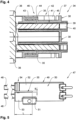
- the Fig. 4 shows a brush module 34 with brushes 35 on slip rings 36.
- the brush module 34 has a housing device 37, which includes at least two housing halves 38.
- a quiver 39 is formed within each housing half 38, which together with a roller band spring 40 forms a brush holder 41.
- a final cover for the collecting device 46 is not shown here.
- the Fig. 5 shows a brush module 47 with two brushes 48 and a housing device 49, which forms a housing body 50.
- the Housing body 50 is held on a fastening bracket 51 on a current-excited synchronous machine, not shown here.
- the housing body 50 also forms two brush holders 52 and 53.
- An air gap 55 is formed between the brush holders 52 and 53 in a housing section 54 of the housing device 49 or the housing body 50 that faces a slip ring. Any brush dust that may be deposited in the area of the brushes 48 cannot bridge a width (B) of the air gap 55 or cannot fill a length (L) of the air gap 55, so that a possible short circuit can be easily prevented by the air gap 55.
Landscapes
- Engineering & Computer Science (AREA)
- Power Engineering (AREA)
- Motor Or Generator Current Collectors (AREA)
- Motor Or Generator Frames (AREA)
Description
- Die Erfindung betrifft ein Bürstenmodul für eine rotierende elektrische Maschine sowie eine elektrische Maschine, insbesondere stromerregte Synchronmaschine, wobei das Bürstenmodul zumindest zwei Bürsten zur elektrischen Kontaktierung von Schleifringen der Maschine aufweist, wobei das Bürstenmodul eine Gehäusevorrichtung und Bürstenhalter zur Aufnahme und Halterung der Bürsten aufweist, wobei die Gehäusevorrichtung eine Auffangeinrichtung zur Aufnahme von Bürstenstaub der Bürsten aufweist.
- Derartige Bürstenmodule sind hinreichend bekannt und dienen regelmä-βig zur Stromübertragung auf eine drehende Welle einer stromerregten Synchronmaschine. An der Welle sind Schleifringe angeordnet, die mit den Bürsten des Bürstenmoduls kontaktiert sind. Die Bürsten sind in Bürstenhaltern oder sogenannten Bürstenköchern in radialer Richtung relativ zur Welle bewegbar aufgenommen und werden über eine Feder mit einer Federkraft beaufschlagt und so gegen die Schleifringe gedrückt. Da das Bürstenmodul zumindest zwei Bürsten aufweist, können zwei beispielsweise unterschiedlich gepolte Schleifringe mit dem Bürstenmodul kontaktiert werden. Die Bürsten selbst bestehen regelmäßig aus Kohlestoff bzw. Graphit mit gegebenenfalls metallischen Anteilen und sind über eine Litze elektrisch kontaktiert.
- Während eines Betriebs der elektrischen Maschine kommt es stets zu einem Abrieb des Materials der Bürsten, so dass die Bürsten kontinuierlich aufgebraucht und in ihrer Länge verkürzt werden. Der Abrieb gelangt in Form von Bürstenstaub bzw. Graphitstaub in eine Umgebung des Bürstenmoduls und lagert sich dort ab.
- Nachteilig ist, dass der Bürstenstaub eine leitfähige Staubfläche ausbildet, welche ihrerseits eine sogenannte Kriechstrecke für eine elektrische Ladung ausbildet. So kann eine Kriechstrecke zwischen einem metallischen Bauteil der elektrischen Maschine und einer Bürste bzw. einem Bürstenhalter durch den Bürstenstaub ausgebildet werden (Masseschluss). Weiter kann eine Kriechstrecke zwischen zwei Polen bzw. Bürsten oder Bürstenhaltern ausgebildet werden (Kurzschluss). Bei einem Masseschluss werden Spannungen auf leitende Teile der elektrischen Maschine oder auch eine Umgebung der elektrischen Maschine übertragen und bei einem Kurzschluss jeweils zwischen den elektrischen Polen, was zu einer Funktionsstörung der elektrischen Maschine und/oder einer für einen Antrieb dieser Maschine erforderlichen Leistungselektronik führt. Zwar ist es bekannt bei stromerregten Synchronmaschinen elektrische Energie auch berührungslos, zum Beispiel über induktive Kopplung, auf einen Läufer zu übertragen, diese Systeme sind jedoch aufgrund ihrer technischen Komplexität wesentlich teurer als Bürstenmodule.
- Die
DE 10 2012 203 098 A1 offenbart ein Bürstenmodul, mit dem Bürsten an einem Ende einer Welle gehaltert und gegenüber einer Umgebung dicht abgeschlossen werden. Bei diesem Bürstenmodul kann eine Kühlung der Bürsten dadurch erfolgen, dass Luft in einem geschlossenen Kreislauf zirkuliert wird, wobei eine sogenannte Filtereinrichtung zum Entfernen von Bürstenstaub aus der Luft vorgesehen ist. - Die
EP 1 551 094 A1 betrifft eine rotierende elektrische Maschine für ein Fahrzeug umfassend ein Bürstenmodul, wobei das Bürstenmodul eine Überwachungseinheit aufweist, um eine Abnutzung einer Bürste des Bürstenmoduls zu überwachen. - Die
DE 101 55 221 A1 zeigt eine elektrische Maschine, insbesondere einen Drehstromgenerator für Kraftfahrzeuge, welche ebenfalls ein Bürstenmodul aufweist. Ein derartiges Bürstenmodul umfasst eine Gehäusevorrichtung und einen Bürstenhalter zur Aufnahme und Halterung von Bürsten, wobei die Gehäusevorrichtung einen Hohlraum ausbildet, in welchem der Bürstenstaub gesammelt werden kann. Ein Abschnitt der Gehäusevorrichtung ist dabei aus porösem Material ausgebildet, welches luftdurchlässig ist, wodurch eine Überhitzung von Luft in dem Hohlraum vermieden werden kann. - Die
US 2008/061652 A1 bezieht sich auf einen Wechselstromgenerator für ein Fahrzeug. An dem Wechselstromgenerator ist ein Bürstenmodul mit zwei Bürsten, über die jeweils Schleifringe kontaktiert werden, angeordnet. Das Bürstenmodul umfasst eine Gehäusevorrichtung zur Halterung der Bürsten sowie eine Auffangeinrichtung zur Aufnahme von Bürstenstaub. Die Bürsten sind relativ zur Welle in einer axialen Richtung an der Welle angeordnet. Die Gehäusevorrichtung ist offenbar so ausgebildet, dass ein Wellenende des Wechselstromgenerators mit den Schleifringen von der Gehäusevorrichtung vollständig abgedeckt ist. Der Bürstenstaub kann in einem Auffangbehälter mit einer taschenförmigen Aufnahme gesammelt werden. - Der vorliegenden Erfindung liegt daher die Aufgabe zugrunde, ein Bürstenmodul bzw. eine elektrische Maschine mit einem Bürstenmodul vorzuschlagen, welches bzw. welche eine Ausbildung von Kriechstrecken vermeidet.
- Diese Aufgabe wird durch ein Bürstenmodul mit den Merkmalen des Anspruchs 1 und eine elektrische Maschine mit den Merkmalen des Anspruchs 14 gelöst.
- Das erfindungsgemäße Bürstenmodul für eine rotierende elektrische Maschine, insbesondere stromerregte Synchronmaschine, weist zumindest zwei Bürsten zur elektrischen Kontaktierung von Schleifringen der Maschine auf, wobei das Bürstenmodul eine Gehäusevorrichtung und Bürstenhalter zur Aufnahme und Halterung der Bürsten aufweist, wobei die Gehäusevorrichtung eine Auffangeinrichtung zur Aufnahme von Bürstenstaub der Bürsten aufweist, wobei die Auffangeinrichtung Taschen zur Aufnahme von Bürstenstaub aufweist, wobei die Taschen in einer Rotationsrichtung eines Schleifrings, nachfolgend der Bürste angeordnet sind, wobei die Taschen durch in der Rotationsrichtung verlaufende Rippen ausgebildet sind, wobei die Rippen von der Gehäusevorrichtung ausgebildet oder in die Gehäusevorrichtung eingesetzt sind, wobei für jede der Bürsten eine eigene Auffangeinrichtung ausgebildet ist.
- Das Bürstenmodul ist insbesondere so ausgebildet, dass nicht bloß die Bürstenhalter an den jeweiligen Schleifringen angeordnet sind, sondern die Gehäusevorrichtung die Bürsten bzw. die Bürstenhalter aufnimmt und haltert. Die zumindest zwei Bürsten werden daher zusammen an der Gehäusevorrichtung gehaltert. Dabei ist vorgesehen, dass die Gehäusevorrichtung eine Auffangeinrichtung für den Bürstenstaub der Bürsten aufweist. Die Auffangeinrichtung ist so ausgebildet, dass der von den Bürsten abgeriebene Bürstenstaub und gegebenenfalls auch Abrieb von den Schleifringen während eines Betriebs der elektrischen Maschine bzw. einer Rotation der Schleifringe in die Auffangeinrichtung gelangt. Der Bürstenstaub wird demnach von der Auffangeinrichtung absorbiert bzw. zumindest zu einem überwiegenden Anteil aufgefangen und kontrolliert gespeichert. Dadurch kann vermieden werden, dass sich größere Mengen Bürstenstaub im Bereich der Bürsten bzw. Bürstenhalter so ablagern, dass eine elektrische Kriechstrecke zwischen den Bürsten bzw. Bürstenhaltern oder anderen elektrisch leitenden Teilen der elektrischen Maschine oder einer Umgebung ausgebildet wird. Insgesamt kann so eine mögliche Fehlfunktion der elektrischen Maschine infolge eines Verschleißes der Bürsten wirkungsvoll verhindert werden.
- Erfindungsgemäß weist die Auffangeinrichtung Taschen zur Aufnahme von Bürstenstaub auf, wobei die Taschen in einer Rotationsrichtung eines Schleifrings, nachfolgend der Bürste angeordnet sind. Von den Bürsten abgeriebener Bürstenstaub wird regelmäßig in Rotationsrichtung des Schleifrings gefördert, so dass den Bürsten nachgeordnet Taschen oder taschenartige Ausnehmungen angeordnet sind, in denen sich dieser Bürstenstaub ansammeln kann. Die Taschen können dabei von der Gehäusevorrichtung ausgebildet werden oder auch separat von dieser ausgebildet sein. Dadurch, dass der Bürstenstaub in den Taschen aufgefangen wird, kann er sich kontrolliert in den Taschen anlagern, ohne dass eine Kriechstrecke ausgebildet wird.
- Erfindungsgemäß sind die Taschen durch in Rotationsrichtung verlaufende Rippen ausgebildet. Die Rippen können koaxial zu den Schleifringen verlaufen, wobei durch die Rippen eine besonders große Fläche zum Anhaften des Bürstenstaubs zur Verfügung gestellt wird.
- Erfindungsgemäß sind die Rippen von der Gehäusevorrichtung ausgebildet oder in die Gehäusevorrichtung eingesetzt.
- Erfindungsgemäß ist für jede der Bürsten eine eigene Auffangeinrichtung ausgebildet.
- Die Gehäusevorrichtung kann zumindest die Bürsten, vorzugsweise die Bürsten und die Bürstenhalter vollständig umgeben. Wenn die Gehäusevorrichtung so ausgebildet ist, dass die Bürsten bzw. ein Ende der Bürsten, welches mit den Schleifringen kontaktiert ist, von der Gehäusevorrichtung eingehaust ist, kann vermieden werden, dass Bürstenstaub in eine Umgebung der Bürsten, außerhalb der Gehäusevorrichtung, gelangt.
- Die Auffangeinrichtung kann dann innerhalb der Gehäusevorrichtung integriert sein. Die Auffangeinrichtung kann prinzipiell auch von der Gehäusevorrichtung getrennt ausgebildet und in diese eingesetzt sein. Alternativ kann die Auffangeinrichtung von der Gehäusevorrichtung ausgebildet werden. Die Gehäusevorrichtung kann auch so ausgebildet sein, dass diese neben den Bürsten auch die Bürstenhalter vollständig umgibt, um einen unerwünschten Austritt von Bürstenstaub zu verhindern. Weiter kann die Gehäusevorrichtung die Bürstenhalter auch nur teilweise umgeben.
- Die Gehäusevorrichtung kann so ausgebildet sein, dass sie Schleifringe zumindest abschnittsweise, vorzugsweise vollständig koaxial umgibt. So kann die Gehäusevorrichtung beispielsweise in Gestalt eines Kreisringsegments oder an eine Kreisform der Welle angepasst ausgebildet sein. Die Gehäusevorrichtung kann auch in Art eines vollständigen Kreisrings ausgebildet sein und die Schleifringe in radialer Richtung vollständig umfassen.
- So kann die Gehäusevorrichtung gegenüber einer Umgebung staubdicht bzw. überwiegend staubdicht abgedichtet sein. So kann verhindert werden, dass Bürstenstaub aus der Gehäusevorrichtung heraus in eine Umgebung der Schleifringe gelangt und so gegebenenfalls eine Kriechstrecke zu anderen elektrisch leitenden Bauteilen der elektrischen Maschine ausbildet. Eine im Wesentlichen staubdichte Abdichtung gegenüber einer rotierenden Welle kann beispielsweise mittels einer Labyrinthdichtung, einer Dichtlippe, einer Bürstendichtung oder anderen geeigneten Dichtungen ausgebildet werden. Dabei kann vorgesehen sein, dass dennoch ein Austausch von Luft zwischen der Umgebung und einem Inneren der Gehäusevorrichtung, beispielsweise zu Kühlungszwecken, erfolgt.
- Weiter kann die Auffangeinrichtung ein Bürstenstaub absorbierendes Material aufweisen. Diese Material kann ein poröses oder auch ein luftdurchlässiges Material sein, wie beispielsweise ein textiles Material, insbesondere ein Vlies. Ein Vlies kann eine große Menge an Bürstenstaub aufnehmen bzw. absorbieren, derart, dass sich der Bürstenstaub auch nicht mehr von dem Vlies ohne Weiteres ablösen kann. So kann sichergestellt werden, dass Bürstenstaub von der Auffangeinrichtung, beispielsweise infolge von Schwingungen, nicht wieder abgegeben werden kann. Das absorbierende Material kann beispielsweise im oder an Taschen der Auffangeinrichtung oder auch an einer Wandung der Gehäusevorrichtung angeordnet sein. Weiter kann vorgesehen sein, das absorbierende Material zu Reinigungszwecken austauschbar anzuordnen.
- Die Gehäusevorrichtung kann aus zwei kreisringförmigen Gehäusehälften ausgebildet sein. Die kreisringsförmigen Gehäusehälften können beispielsweise zusammensteckbar oder auch gegeneinander in radialer Richtung verdrehbar ausgebildet sein. Wenn die Gehäusehälften identisch ausgebildet sind, sind sie besonders kostengünstig herstellbar. Optional ist es auch möglich die Gehäusevorrichtung aus zumindest zwei kreissegmentförmigen Gehäusehälften auszubilden, wobei dann eine Teilungsebene der Gehäusehälften in axialer Richtung verläuft. Hinsichtlich der Anordnung der Bürsten kann jede der Gehäusehälften zumindest eine Bürste aufnehmen.
- Die Gehäusevorrichtung kann die Bürstenhalter und/oder die Auffangvorrichtungen ausbilden. Wenn die Gehäusevorrichtung durch ein Spritzgussverfahren, beispielsweise aus Kunststoff, hergestellt wird, ist das Bürstenmodul dann besonders kostengünstig herstellbar. Ein Köcher des Bürstenhalters kann dann einfach als eine Ausnehmung in der Gehäusevorrichtung ausgebildet sein, wobei die Auffangvorrichtung als eine einfache Tasche innerhalb der Gehäusevorrichtung ausgebildet sein kann.
- Die Bürstenhalter können in axialer Richtung, relativ bezogen auf die Schleifringe, voneinander beabstandet sein, dies ist insbesondere dann möglich, wenn zumindest zwei Schleifringe mit zumindest jeweils einer Bürste kontaktiert werden sollen.
- Weiter können zumindest zwei Bürsten zur elektrischen Kontaktierung eines Schleifrings vorgesehen sein, wobei die jeweiligen Bürstenhalter in radialer Richtung, relativ bezogen auf den Schleifring, voneinander beabstandet sein können. Beispielsweise können die zwei Bürstenhalter dann achsensymmetrisch zu den Schleifringen, einander gegenüberliegend, angeordnet sein. Eine Ausbildung einer möglichen Kriechstrecke zwischen den Bürsten bzw. Bürstenhaltern ist dann erheblich erschwert. Die Bürstenhalter können in einem maximalen Relativabstand an der Gehäusevorrichtung angeordnet sein. So können die Bürstenhalter in axialer als auch in radialer Richtung so weit als möglich voneinander beabstandet durch die Ausbildung der Gehäusevorrichtung angeordnet sein.
- Ein alternatives Bürstenmodul für eine rotierende elektrische Maschine, insbesondere stromerregte Synchronmaschine, kann zumindest zwei Bürsten zur elektrischen Kontaktierung von Schleifringen der Maschine aufweisen, wobei das Bürstenmodul eine Gehäusevorrichtung und Bürstenhalter zur Aufnahme und Halterung der Bürsten aufweisen kann, wobei die Gehäusevorrichtung derart ausgebildet sein kann, dass die Bürstenhalter voneinander beabstandet sind, wobei die Gehäusevorrichtung an einem Schleifringen zugewandten Gehäuseabschnitt der Gehäusevorrichtung zumindest abschnittsweise einen Luftspalt zwischen den Bürstenhaltern ausbilden kann, wobei die Gehäusevorrichtung einen einzelnen Gehäusekörper aufweisen und die Bürstenhalter ausbilden kann, wobei der Luftspalt in dem Gehäusekörper und eine Breite des Luftspaltes in Abhängigkeit einer vorausgesetzten Betriebsspannung an den Bürsten ausgebildet sein können.
- Demnach sind die Bürstenhalter in einer gemeinsamen Gehäusevorrichtung aufgenommen bzw. werden von dieser ausgebildet, wobei die Gehäusevorrichtung so beschaffen ist, dass ein Abstand zwischen den Bürstenhaltern ausgebildet wird. Da sich insbesondere an den Schleifringen zugewandten Gehäuseabschnitt der Gehäusevorrichtung Bürstenstaub der Bürsten ablagern kann, ist vorgesehen, dass die Gehäusevorrichtung einen Luftspalt zwischen den Bürstenhaltern an diesem Gehäuseabschnitt ausbildet. Selbst wenn es dann zu einer Ablagerung von Bürstenstaub an dem Schleifringen zugewandten Gehäuseabschnitt der Gehäusevorrichtung kommen sollte, muss diese Ablagerung von Bürstenstaub so groß sein, dass dieser Luftspalt überbrückt wird, damit eine Kriechstrecke zwischen den Bürsten bzw. Polen ausgebildet wird. Der Luftspalt ist jedoch so bemessen, dass er kaum mit Bürstenstaub ausfüllbar bzw. überbrückbar ist. So kann mit einer einfachen Ausgestaltung der Gehäusevorrichtung die Bildung einer Kriechstrecke durch Bürstenstaub verhindert werden.
- Die Gehäusevorrichtung kann einen einzelnen Gehäusekörper aufweisen und gleichzeitig die Bürstenhalter ausbilden. Der Luftspalt in dem Gehäusekörper kann auch so ausgebildet sein, dass eine Breite des Luftspaltes in Abhängigkeit einer vorausgesetzten Betriebsspannung an den Bürsten ausgebildet ist. Unter der vorausgesetzten Betriebsspannung wird eine für einen Regelbetrieb vorgesehene, maximale Betriebsspannung an den Bürsten verstanden. Die Breite bzw. eine Mindestbreite kann dann leicht auf Basis einer angenommenen Durchschlagsfestigkeit von 1 kV/mm für Luft nach der Norm IEC 60243 errechnet werden.
- Der Luftspalt kann in dem Gehäusekörper ausgebildet sein und ≥5 mm lang sein. Bei einem Luftspalt dieser Länge kann eine Überbrückung bzw. Ausbildung einer Kriechstrecke mittels Bürstenstaub nahezu ausgeschlossen werden. Eine Länge des Luftspalts kann mehrere Zentimeter betragen.
- Besonders vorteilhaft ist es, wenn der Bürstenhalter oder die Bürste eine Meldeeinrichtung zur Verschleißerkennung aufweist. Die Meldeeinrichtung kann durch einen Schalter bzw. einen Kontakt am Bürstenhalter, der eine Länge einer Bürste detektieren kann, oder einen Kontakt innerhalb der Bürsten, der bei einem bestimmten Verschleißgrad ausgelöst wird, ausgebildet sein.
- Die erfindungsgemäße elektrische Maschine, insbesondere stromerregte Synchronmaschine, weist ein erfindungsgemäßes Bürstenmodul auf. Weitere vorteilhafte Ausführungsformen der elektrischen Maschine ergeben sich aus den auf die Vorrichtungsansprüche rückbezogenen Unteransprüchen.
- Nachfolgend werden bevorzugte Ausführungsformen der Erfindung unter Bezugnahme auf die beigefügten Zeichnungen näher erläutert.
- Es zeigen:
- Fig. 1
- eine Querschnittansicht einer ersten Ausführungsform eines Bürstenmoduls;
- Fig. 2
- eine perspektivische Teilansicht einer zweiten Ausführungsform eines Bürstenmoduls;
- Fig. 3
- eine Querschnittansicht des Bürstenmoduls aus
Fig. 1 ; - Fig. 4
- eine Längsschnittansicht einer dritten Ausführungsform eines Bürstenmoduls;
- Fig. 5
- eine Seitenansicht einer vierten Ausführungsform eines Bürstenmoduls.
- Die
Fig. 1 zeigt eine schematische Schnittansicht eines Bürstenmoduls 10 an einem Schleifring 11 einer stromerregten Synchronmaschine. Das Bürstenmodul 10 weist zwei Bürsten 12 zur elektrischen Kontaktierung des Schleifrings 11 sowie eine Gehäusevorrichtung 13 mit Bürstenhalter 14 auf. Die Bürsten 12 sind in den Bürstenhaltern 14 in Richtung einer Längsachse 15 der Bürstenhalter 14 beweglich gelagert und werden mittels einer hier nicht gezeigten Feder, beispielsweise einer Schraubenfeder, einer Blattfeder oder einer Rollbandfeder gegen den Schleifring 11 gedrückt. Die Bürstenhalter 14 sind um einen Winkel α relativ zueinander versetzt zu einer Achse 16 des Schleifrings 11 angeordnet. Die Gehäusevorrichtung 13 ist kreisringsförmig ausgebildet und weist eine äußere Gehäusewandung 17 auf, die einen Innenraum 18 ausbildet, der gegenüber einer Umgebung 19 im Wesentlichen staubdicht abgedichtet ist. In der Gehäusewandung 17 ist eine Öffnung 20 zur Durchführung hier nicht dargestellter elektrischer Leitungen mit einem Dichtelement, welches die Öffnung 20 abdichtet, ausgebildet. Innerhalb der Gehäusevorrichtung 13 sind Auffangeinrichtungen 21 zur Aufnahme von Bürstenstaub der Bürsten 12 ausgebildet. Die Auffangeinrichtungen sind aus Rippen 22, 23, 24 ausgebildet, die Taschen 25, 26 bzw. 27 ausbilden. Die Rippen 22 bis 24 verlaufen im Wesentlichen in einer hier mit einem Pfeil 28 gekennzeichneten Rotationsrichtung des Schleifrings 11. Bürstenstaub wird dann, wie ausFig. 3 ersichtlich ist, in Richtung von Pfeilen 29 von den Bürsten 12 bei einer Rotation des Schleifrings 11 weggefördert und gelangt in die Taschen 25, 26 und 27. - Wie aus
Fig. 2 ersichtlich ist, kann ein Bürstenmodul 30 auch eine hier nicht vollständig dargestellte Gehäusevorrichtung 31 aufweisen, welche aus zwei Gehäusehälften 32 ausgebildet ist. Die Gehäusehälfte 32 bildet hier eine Auffangeinrichtung 33 aus. - Die
Fig. 4 zeigt ein Bürstenmodul 34 mit Bürsten 35 an Schleifringen 36. Das Bürstenmodul 34 weist eine Gehäusevorrichtung 37, die zumindest zwei Gehäusehälften 38 umfasst, auf. Innerhalb jeder Gehäusehälfte 38 ist ein Köcher 39 ausgebildet, der zusammen mit einer Rollbandfeder 40 einen Bürstenhalter 41 ausbildet. Benachbart dem Bürstenhalter 41 ist an einer Seitenfläche 42 der Gehäusehälfte 38 eine Anzahl Rippen 43, 44 und 45 ausgebildet, die hier nicht näher ersichtliche Taschen einer Auffangeinrichtung 46 für Bürstenstaub ausbilden. Eine abschließende Abdeckung der Auffangeinrichtung 46 ist hier nicht dargestellt. - Die
Fig. 5 zeigt ein Bürstenmodul 47 mit zwei Bürsten 48 und einer Gehäusevorrichtung 49, die einen Gehäusekörper 50 ausbildet. Der Gehäusekörper 50 ist an einer Befestigungslasche 51 an einer hier nicht näher dargestellten stromerregten Synchronmaschine gehaltert. Auch bildet der Gehäusekörper 50 zwei Bürstenhalter 52 und 53 aus. In einem einem Schleifring zugewandten Gehäuseabschnitt 54 der Gehäusevorrichtung 49 bzw. des Gehäusekörpers 50 ist ein Luftspalt 55 zwischen den Bürstenhaltern 52 und 53 ausgebildet. Eventuell im Bereich der Bürsten 48 sich ablagernder Bürstenstaub kann eine Breite (B) des Luftspalts 55 nicht überbrücken bzw. eine Länge (L) des Luftspalts 55 nicht ausfüllen, so dass durch den Luftspalt 55 ein eventueller Kurschluss einfach verhindert werden kann.
Claims (14)
- Bürstenmodul (10, 30, 34) für eine rotierende elektrische Maschine, insbesondere stromerregte Synchronmaschine, wobei das Bürstenmodul (10, 30, 34) zumindest zwei Bürsten (12, 35) zur elektrischen Kontaktierung von Schleifringen (11, 36) der elektrischen Maschine aufweist, wobei das Bürstenmodul (10, 30, 34) eine Gehäusevorrichtung (13, 31, 37) und Bürstenhalter (14, 41) zur Aufnahme und Halterung der Bürsten (12, 35) aufweist, wobei die Gehäusevorrichtung (13, 31, 37) eine Auffangeinrichtung (21, 33, 46) zur Aufnahme von Bürstenstaub der Bürsten (12, 35) aufweist,
dadurch gekennzeichnet,
dass die Auffangeinrichtung (21, 33, 46) Taschen (25, 26, 27) zur Aufnahme von Bürstenstaub aufweist, wobei die Taschen (25, 26, 27) in einer Rotationsrichtung (28) eines Schleifrings (11, 36), nachfolgend der Bürste (12, 35) angeordnet sind, wobei die Taschen (25, 26, 27) durch in der Rotationsrichtung (28) verlaufende Rippen (22, 23, 24, 43, 44, 45) ausgebildet sind, wobei die Rippen (22, 23, 24, 43, 44, 45) von der Gehäusevorrichtung (13, 31, 37) ausgebildet oder in die Gehäusevorrichtung (13, 31, 37) eingesetzt sind, wobei für jede der Bürsten (12, 35) eine eigene Auffangeinrichtung (21, 33, 46) ausgebildet ist. - Bürstenmodul (10, 30, 34) nach Anspruch 1,
dadurch gekennzeichnet,
dass die Gehäusevorrichtung (13, 31, 37) zumindest die Bürsten (12, 35), vorzugsweise die Bürsten (12, 35) und die Bürstenhalter (14, 41) vollständig umgibt. - Bürstenmodul (10, 30, 34) nach Anspruch 1 oder 2,
dadurch gekennzeichnet,
dass die Gehäusevorrichtung (13, 31, 37) so ausgebildet ist, dass sie Schleifringe (11, 36) zumindest abschnittsweise, vorzugsweise vollständig koaxial umgibt. - Bürstenmodul (10, 30, 34) nach einem der vorangehenden Ansprüche,
dadurch gekennzeichnet,
dass die Gehäusevorrichtung (13, 31, 37) gegenüber einer Umgebung (19) staubdicht abgedichtet ist. - Bürstenmodul (10, 30, 34) nach einem der vorangehenden Ansprüche,
dadurch gekennzeichnet,
dass die Auffangeinrichtung (21, 33, 46) ein Bürstenstaub absorbierendes Material aufweist. - Bürstenmodul (10, 30, 34) nach einem der vorangehenden Ansprüche,
dadurch gekennzeichnet,
dass die Gehäusevorrichtung (13, 31, 37) aus zwei kreisringförmigen Gehäusehälften (32, 38) ausgebildet ist. - Bürstenmodul (10, 30, 34) nach einem der vorangehenden Ansprüche,
dadurch gekennzeichnet,
dass die Gehäusevorrichtung (13, 31, 37) die Bürstenhalter (14, 41) und/oder die Auffangvorrichtungen (21, 33, 46) ausbildet. - Bürstenmodul (10, 30, 34) nach einem der vorangehenden Ansprüche,
dadurch gekennzeichnet,
dass die Bürstenhalter (14, 41) in axialer Richtung, relativ bezogen auf die Schleifringe (11, 36), voneinander beabstandet sind. - Bürstenmodul (10, 30, 34) nach einem der vorangehenden Ansprüche,
dadurch gekennzeichnet,
dass zumindest zwei Bürsten (12, 35) zur elektrischen Kontaktierung eines Schleifrings (11, 36) vorgesehen sind, wobei die jeweiligen Bürstenhalter (14, 41) in radialer Richtung, relativ bezogen auf den Schleifring (11, 36), voneinander beabstandet sind. - Bürstenmodul (10, 30, 34) nach einem der vorangehenden Ansprüche,
dadurch gekennzeichnet,
dass die Bürstenhalter (14, 41) in einem maximalen Relativabstand angeordnet sind. - Bürstenmodul (47) nach einem der vorangehenden Ansprüche, dadurch gekennzeichnet,
dass die Gehäusevorrichtung (49) derart ausgebildet ist, dass die Bürstenhalter (52, 53) voneinander beabstandet sind, wobei die Gehäusevorrichtung (49) an einem Schleifringen zugewandten Gehäuseabschnitt (54) der Gehäusevorrichtung (49) zumindest abschnittsweise einen Luftspalt (55) zwischen den Bürstenhaltern (52, 53) ausbildet, wobei die Gehäusevorrichtung (49) einen einzelnen Gehäusekörper (50) aufweist und die Bürstenhalter (52, 53) ausbildet, wobei der Luftspalt (55) in dem Gehäusekörper (50) ausgebildet und eine Breite des Luftspaltes (55) in Abhängigkeit einer vorausgesetzten Betriebsspannung an den Bürsten (48) ausgebildet ist. - Bürstenmodul (47) nach Anspruch 11,
dadurch gekennzeichnet,
dass der Luftspalt (55) in dem Gehäusekörper (50) ausgebildet und ≥ 5 mm lang ist. - Bürstenmodul (47) nach einem der vorangehenden Ansprüche,
dadurch gekennzeichnet,
dass der Bürstenhalter (14, 41, 52, 53) oder die Bürste (12, 35, 48) eine Meldeeinrichtung zur Verschleißerkennung aufweist. - Elektrische Maschine, insbesondere stromerregte Synchronmaschine, dadurch gekennzeichnet,
dass die elektrische Maschine ein Bürstenmodul (10, 30, 34, 47) nach einem der vorangehenden Ansprüche aufweist.
Applications Claiming Priority (2)
| Application Number | Priority Date | Filing Date | Title |
|---|---|---|---|
| DE102017202549.2A DE102017202549B4 (de) | 2017-02-16 | 2017-02-16 | Bürstenmodul |
| PCT/EP2018/051914 WO2018149615A1 (de) | 2017-02-16 | 2018-01-26 | Bürstenmodul |
Publications (2)
| Publication Number | Publication Date |
|---|---|
| EP3583680A1 EP3583680A1 (de) | 2019-12-25 |
| EP3583680B1 true EP3583680B1 (de) | 2023-10-04 |
Family
ID=61244548
Family Applications (1)
| Application Number | Title | Priority Date | Filing Date |
|---|---|---|---|
| EP18705834.2A Active EP3583680B1 (de) | 2017-02-16 | 2018-01-26 | Bürstenmodul |
Country Status (7)
| Country | Link |
|---|---|
| US (1) | US11146151B2 (de) |
| EP (1) | EP3583680B1 (de) |
| JP (1) | JP6923663B2 (de) |
| KR (1) | KR20190117518A (de) |
| CN (1) | CN110301087B (de) |
| DE (1) | DE102017202549B4 (de) |
| WO (1) | WO2018149615A1 (de) |
Families Citing this family (8)
| Publication number | Priority date | Publication date | Assignee | Title |
|---|---|---|---|---|
| DE202020101256U1 (de) | 2020-03-06 | 2020-03-12 | Chongqing Huaneng Hydro Power Equipment Manufacturing Co., Ltd. | Bürstenanordnung für eine elektrische Maschine sowie eine elektrische Maschine mit der Bürstenanordnung |
| DE102021116230A1 (de) | 2021-06-23 | 2022-12-29 | HELLA GmbH & Co. KGaA | Verfahren zur Projektion einer Führungslinie auf eine Fahrbahn |
| DE102021129114A1 (de) | 2021-11-09 | 2023-05-11 | Bayerische Motoren Werke Aktiengesellschaft | Kontaktiermodul zum elektrischen Anschluss eines Bürstenmoduls einer elektrischen Maschine |
| CN115832804A (zh) * | 2022-11-29 | 2023-03-21 | 深圳市默孚龙科技有限公司 | 电滑环 |
| CN116608896B (zh) | 2023-06-30 | 2023-09-19 | 常州华旋传感技术有限公司 | 电机一体式旋转变压器模拟设备及其模拟方法 |
| DE102023118464A1 (de) * | 2023-07-12 | 2025-01-16 | Bayerische Motoren Werke Aktiengesellschaft | Elektrische Maschine mit einer Spanbrecher-Vorrichtung zum Brechen von Metallspänen |
| JPWO2025120741A1 (de) * | 2023-12-05 | 2025-06-12 | ||
| CN120955430B (zh) * | 2025-10-17 | 2026-02-10 | 大连宜顺精密制造股份有限公司 | 磨屑收集机构、导电机构和高压旋转导电设备 |
Family Cites Families (32)
| Publication number | Priority date | Publication date | Assignee | Title |
|---|---|---|---|---|
| BE795574A (fr) | 1972-02-18 | 1973-08-16 | Roussel Uclaf | Derives du 21-m-sulfobenzoate de 6, 16 alpha-dimethyl 2,4,6-olo /3,2 c/pyrazole 20-one et procede de preparation |
| JPS576372A (en) | 1980-06-12 | 1982-01-13 | Toshiba Corp | Testing device for composite packaged device |
| JPS576372U (de) * | 1980-06-12 | 1982-01-13 | ||
| JPS5814907A (ja) | 1981-07-21 | 1983-01-28 | Toray Ind Inc | 逆浸透膜の保護方法 |
| JPS58149074U (ja) * | 1982-03-29 | 1983-10-06 | 三洋電機株式会社 | 整流子モ−タ |
| JPS62193532A (ja) * | 1986-02-18 | 1987-08-25 | Toshiba Corp | 刷子摩耗検出装置 |
| JPH0556605A (ja) * | 1991-08-21 | 1993-03-05 | Toshiba Corp | 回転電機の集電装置 |
| JPH05139223A (ja) | 1991-11-22 | 1993-06-08 | Alps Electric Co Ltd | 車載用スリツプリング |
| KR0178156B1 (ko) | 1995-09-22 | 1999-05-15 | 정몽원 | 차량용 교류 발전기 |
| FR2780829B1 (fr) | 1998-07-02 | 2000-09-29 | Valeo Equip Electr Moteur | Porte-balais pour alternateur de vehicule, a zones de connexion protegees |
| JP3911879B2 (ja) | 1998-11-02 | 2007-05-09 | 株式会社デンソー | 車両用交流発電機 |
| KR20000056032A (ko) | 1999-02-12 | 2000-09-15 | 에릭 발리베 | 알터네이터의 브러시 가루 배출구조 |
| US6486580B1 (en) | 2000-02-10 | 2002-11-26 | Visteon Global Technologies, Inc. | Bearing retainer assembly |
| US6417595B1 (en) * | 2000-05-24 | 2002-07-09 | Mcmillan Electric Company | Spark suppression dust sealing for a motor apparatus |
| JP3785964B2 (ja) | 2000-08-11 | 2006-06-14 | 株式会社デンソー | 車両用交流発電機 |
| DE10155221A1 (de) * | 2001-11-09 | 2003-05-22 | Bosch Gmbh Robert | Elektrische Maschine, insbesondere Drehstromgenerator für Kraftfahrzeuge |
| US7358640B2 (en) * | 2002-10-07 | 2008-04-15 | Mitsubishi Denki Kabushiki Kaisha | Automotive rotary electric machine |
| US7102266B2 (en) * | 2005-02-08 | 2006-09-05 | Ametek, Inc. | Motor assembly with a sealed commutator/brush interface |
| JP2007097236A (ja) | 2005-09-27 | 2007-04-12 | Hitachi Ltd | 車両用回転電機 |
| DE102006000315A1 (de) * | 2006-06-29 | 2008-01-03 | Hilti Ag | Universalmotor mit Einrichtung zum Entfernen von Staub |
| JP4687604B2 (ja) | 2006-08-02 | 2011-05-25 | 株式会社デンソー | 車両用交流発電機 |
| US7352103B2 (en) * | 2006-08-02 | 2008-04-01 | Ametek, Inc. | Motor assembly with a sealed commutator/brush interface |
| JP4565345B2 (ja) * | 2006-09-11 | 2010-10-20 | 株式会社デンソー | 車両用交流発電機 |
| US7615908B2 (en) | 2006-09-11 | 2009-11-10 | Denso Corporation | Vehicle alternator with improved operation reliability |
| JP2009095153A (ja) | 2007-10-10 | 2009-04-30 | Denso Corp | 車両用交流発電機 |
| JP5844988B2 (ja) | 2011-04-04 | 2016-01-20 | 株式会社豊田中央研究所 | 回転電機 |
| DE102012203098A1 (de) | 2012-02-29 | 2013-04-04 | Continental Automotive Gmbh | Elektrische Maschine mit Bürstensystem |
| US9762015B2 (en) * | 2014-06-10 | 2017-09-12 | General Electric Company | Brush holder apparatus and system |
| WO2016009824A1 (ja) | 2014-07-17 | 2016-01-21 | 国立研究開発法人宇宙航空研究開発機構 | 電動化航空機並びに電動化航空機における電動モータの出力及び数を決定する方法 |
| JP2017005934A (ja) | 2015-06-15 | 2017-01-05 | 日立オートモティブシステムズエンジニアリング株式会社 | 直流モータ |
| CN205004865U (zh) | 2015-09-09 | 2016-01-27 | 九阳股份有限公司 | 食品加工机及其电机组件和电机碳刷盒组件 |
| CN206313581U (zh) * | 2016-12-14 | 2017-07-07 | 浙江万冠电机有限公司 | 一种电机刷架 |
-
2017
- 2017-02-16 DE DE102017202549.2A patent/DE102017202549B4/de not_active Expired - Fee Related
-
2018
- 2018-01-26 CN CN201880012176.5A patent/CN110301087B/zh not_active Expired - Fee Related
- 2018-01-26 US US16/484,561 patent/US11146151B2/en not_active Expired - Fee Related
- 2018-01-26 EP EP18705834.2A patent/EP3583680B1/de active Active
- 2018-01-26 JP JP2019544018A patent/JP6923663B2/ja not_active Expired - Fee Related
- 2018-01-26 KR KR1020197023274A patent/KR20190117518A/ko not_active Withdrawn
- 2018-01-26 WO PCT/EP2018/051914 patent/WO2018149615A1/de not_active Ceased
Also Published As
| Publication number | Publication date |
|---|---|
| DE102017202549B4 (de) | 2021-10-14 |
| DE102017202549A1 (de) | 2018-08-16 |
| EP3583680A1 (de) | 2019-12-25 |
| JP2020508033A (ja) | 2020-03-12 |
| CN110301087A (zh) | 2019-10-01 |
| US20190363617A1 (en) | 2019-11-28 |
| WO2018149615A1 (de) | 2018-08-23 |
| CN110301087B (zh) | 2021-08-20 |
| JP6923663B2 (ja) | 2021-08-25 |
| US11146151B2 (en) | 2021-10-12 |
| KR20190117518A (ko) | 2019-10-16 |
Similar Documents
| Publication | Publication Date | Title |
|---|---|---|
| DE102017202549B4 (de) | Bürstenmodul | |
| DE102017106695B3 (de) | Wälzlager mit integrierter Stromableitfunktion | |
| DE602004011867T2 (de) | Erdungsbürste zur Verminderung des elektrischen Stroms in einer Motorwelle | |
| DE102018115732A1 (de) | Wälzlager mit integrierter Stromableitfunktion | |
| DE102019133889A1 (de) | Elektrische Maschine mit einer Ableitvorrichtung | |
| DE102016106557A1 (de) | Hand-Werkzeugmaschine mit einem Antriebsmotor | |
| DE102016216909A1 (de) | Antriebseinrichtung für ein Kraftfahrzeug, insbesondere einen Kraftwagen, sowie Kraftfahrzeug mit einer solchen Antriebseinrichtung | |
| DE102015108718A1 (de) | Bürstenhaltervorrichtung und -system | |
| DE102016106558A1 (de) | Hand-Werkzeugmaschine mit einem Trennschalter | |
| DE102015107984A1 (de) | Bürstenhaltervorrichtung und -system | |
| DE102016106559A1 (de) | Hand-Werkzeugmaschine mit einem Lüfterrad | |
| DE102019120802A1 (de) | Elektromaschine | |
| DE2423162C2 (de) | Kommutierungsvorrichtung an einer Gleichstrommaschine | |
| DE102018218530A1 (de) | Bürstenvorrichtung zur elektrischen Verbindung eines ersten Elements mit einem zweiten Element, E-Maschine und Antriebsvorrichtung | |
| DE102013212041A1 (de) | Elektrische Maschine, insbesondere Elektromotor | |
| EP2857669A2 (de) | Filtereinrichtung für ein Kraftfahrzeug | |
| DE102011101621A1 (de) | Schleifringeinheit | |
| DE102007032991A1 (de) | Schleifkontakteinrichtung zur Potenzialableitung an einer Werkzeugmaschinenspindel | |
| DE102006058911B4 (de) | Schleifringanordnung | |
| DE102005045960A1 (de) | Elektrische Rotationsmaschine | |
| WO2011098586A1 (de) | Schleifringeinheit | |
| DE102011087788A1 (de) | Elektrische Maschine | |
| DE102019133882A1 (de) | Ableitvorrichtung sowie elektrische Maschine mit der Ableitvorrichtung | |
| DE102018107206A1 (de) | Anordnung zur Erdung einer Welle einer elektrischen Maschine | |
| EP2696443A2 (de) | Multifunktionales Schleifringgehäuse |
Legal Events
| Date | Code | Title | Description |
|---|---|---|---|
| STAA | Information on the status of an ep patent application or granted ep patent |
Free format text: STATUS: UNKNOWN |
|
| STAA | Information on the status of an ep patent application or granted ep patent |
Free format text: STATUS: THE INTERNATIONAL PUBLICATION HAS BEEN MADE |
|
| PUAI | Public reference made under article 153(3) epc to a published international application that has entered the european phase |
Free format text: ORIGINAL CODE: 0009012 |
|
| STAA | Information on the status of an ep patent application or granted ep patent |
Free format text: STATUS: REQUEST FOR EXAMINATION WAS MADE |
|
| 17P | Request for examination filed |
Effective date: 20190906 |
|
| AK | Designated contracting states |
Kind code of ref document: A1 Designated state(s): AL AT BE BG CH CY CZ DE DK EE ES FI FR GB GR HR HU IE IS IT LI LT LU LV MC MK MT NL NO PL PT RO RS SE SI SK SM TR |
|
| AX | Request for extension of the european patent |
Extension state: BA ME |
|
| DAV | Request for validation of the european patent (deleted) | ||
| DAX | Request for extension of the european patent (deleted) | ||
| STAA | Information on the status of an ep patent application or granted ep patent |
Free format text: STATUS: EXAMINATION IS IN PROGRESS |
|
| 17Q | First examination report despatched |
Effective date: 20200629 |
|
| REG | Reference to a national code |
Ref country code: DE Ref legal event code: R079 Free format text: PREVIOUS MAIN CLASS: H02K0005140000 Ipc: H02K0019000000 |
|
| GRAP | Despatch of communication of intention to grant a patent |
Free format text: ORIGINAL CODE: EPIDOSNIGR1 |
|
| STAA | Information on the status of an ep patent application or granted ep patent |
Free format text: STATUS: GRANT OF PATENT IS INTENDED |
|
| RIC1 | Information provided on ipc code assigned before grant |
Ipc: H02K 23/18 20060101ALI20230228BHEP Ipc: H02K 13/00 20060101ALI20230228BHEP Ipc: H02K 5/14 20060101ALI20230228BHEP Ipc: H02K 19/00 20060101AFI20230228BHEP |
|
| INTG | Intention to grant announced |
Effective date: 20230403 |
|
| GRAS | Grant fee paid |
Free format text: ORIGINAL CODE: EPIDOSNIGR3 |
|
| RBV | Designated contracting states (corrected) |
Designated state(s): AL AT BE BG CH CY CZ DK EE ES FI FR GB GR HR HU IE IS IT LI LT LU LV MC MK MT NL NO PL PT RO RS SE SI SK SM TR |
|
| REG | Reference to a national code |
Ref country code: DE Ref legal event code: R108 |
|
| GRAA | (expected) grant |
Free format text: ORIGINAL CODE: 0009210 |
|
| STAA | Information on the status of an ep patent application or granted ep patent |
Free format text: STATUS: THE PATENT HAS BEEN GRANTED |
|
| AK | Designated contracting states |
Kind code of ref document: B1 Designated state(s): AL AT BE BG CH CY CZ DK EE ES FI FR GB GR HR HU IE IS IT LI LT LU LV MC MK MT NL NO PL PT RO RS SE SI SK SM TR |
|
| REG | Reference to a national code |
Ref country code: GB Ref legal event code: FG4D Free format text: NOT ENGLISH |
|
| REG | Reference to a national code |
Ref country code: CH Ref legal event code: EP |
|
| REG | Reference to a national code |
Ref country code: IE Ref legal event code: FG4D Free format text: LANGUAGE OF EP DOCUMENT: GERMAN |
|
| REG | Reference to a national code |
Ref country code: LT Ref legal event code: MG9D |
|
| REG | Reference to a national code |
Ref country code: NL Ref legal event code: MP Effective date: 20231004 |
|
| PG25 | Lapsed in a contracting state [announced via postgrant information from national office to epo] |
Ref country code: NL Free format text: LAPSE BECAUSE OF FAILURE TO SUBMIT A TRANSLATION OF THE DESCRIPTION OR TO PAY THE FEE WITHIN THE PRESCRIBED TIME-LIMIT Effective date: 20231004 |
|
| P01 | Opt-out of the competence of the unified patent court (upc) registered |
Effective date: 20240227 |
|
| PG25 | Lapsed in a contracting state [announced via postgrant information from national office to epo] |
Ref country code: GR Free format text: LAPSE BECAUSE OF FAILURE TO SUBMIT A TRANSLATION OF THE DESCRIPTION OR TO PAY THE FEE WITHIN THE PRESCRIBED TIME-LIMIT Effective date: 20240105 |
|
| PG25 | Lapsed in a contracting state [announced via postgrant information from national office to epo] |
Ref country code: IS Free format text: LAPSE BECAUSE OF FAILURE TO SUBMIT A TRANSLATION OF THE DESCRIPTION OR TO PAY THE FEE WITHIN THE PRESCRIBED TIME-LIMIT Effective date: 20240204 |
|
| PG25 | Lapsed in a contracting state [announced via postgrant information from national office to epo] |
Ref country code: LT Free format text: LAPSE BECAUSE OF FAILURE TO SUBMIT A TRANSLATION OF THE DESCRIPTION OR TO PAY THE FEE WITHIN THE PRESCRIBED TIME-LIMIT Effective date: 20231004 |
|
| PG25 | Lapsed in a contracting state [announced via postgrant information from national office to epo] |
Ref country code: ES Free format text: LAPSE BECAUSE OF FAILURE TO SUBMIT A TRANSLATION OF THE DESCRIPTION OR TO PAY THE FEE WITHIN THE PRESCRIBED TIME-LIMIT Effective date: 20231004 |
|
| PG25 | Lapsed in a contracting state [announced via postgrant information from national office to epo] |
Ref country code: LT Free format text: LAPSE BECAUSE OF FAILURE TO SUBMIT A TRANSLATION OF THE DESCRIPTION OR TO PAY THE FEE WITHIN THE PRESCRIBED TIME-LIMIT Effective date: 20231004 Ref country code: IS Free format text: LAPSE BECAUSE OF FAILURE TO SUBMIT A TRANSLATION OF THE DESCRIPTION OR TO PAY THE FEE WITHIN THE PRESCRIBED TIME-LIMIT Effective date: 20240204 Ref country code: GR Free format text: LAPSE BECAUSE OF FAILURE TO SUBMIT A TRANSLATION OF THE DESCRIPTION OR TO PAY THE FEE WITHIN THE PRESCRIBED TIME-LIMIT Effective date: 20240105 Ref country code: ES Free format text: LAPSE BECAUSE OF FAILURE TO SUBMIT A TRANSLATION OF THE DESCRIPTION OR TO PAY THE FEE WITHIN THE PRESCRIBED TIME-LIMIT Effective date: 20231004 Ref country code: BG Free format text: LAPSE BECAUSE OF FAILURE TO SUBMIT A TRANSLATION OF THE DESCRIPTION OR TO PAY THE FEE WITHIN THE PRESCRIBED TIME-LIMIT Effective date: 20240104 Ref country code: PT Free format text: LAPSE BECAUSE OF FAILURE TO SUBMIT A TRANSLATION OF THE DESCRIPTION OR TO PAY THE FEE WITHIN THE PRESCRIBED TIME-LIMIT Effective date: 20240205 |
|
| PGFP | Annual fee paid to national office [announced via postgrant information from national office to epo] |
Ref country code: GB Payment date: 20240124 Year of fee payment: 7 |
|
| PG25 | Lapsed in a contracting state [announced via postgrant information from national office to epo] |
Ref country code: SE Free format text: LAPSE BECAUSE OF FAILURE TO SUBMIT A TRANSLATION OF THE DESCRIPTION OR TO PAY THE FEE WITHIN THE PRESCRIBED TIME-LIMIT Effective date: 20231004 Ref country code: RS Free format text: LAPSE BECAUSE OF FAILURE TO SUBMIT A TRANSLATION OF THE DESCRIPTION OR TO PAY THE FEE WITHIN THE PRESCRIBED TIME-LIMIT Effective date: 20231004 Ref country code: PL Free format text: LAPSE BECAUSE OF FAILURE TO SUBMIT A TRANSLATION OF THE DESCRIPTION OR TO PAY THE FEE WITHIN THE PRESCRIBED TIME-LIMIT Effective date: 20231004 Ref country code: NO Free format text: LAPSE BECAUSE OF FAILURE TO SUBMIT A TRANSLATION OF THE DESCRIPTION OR TO PAY THE FEE WITHIN THE PRESCRIBED TIME-LIMIT Effective date: 20240104 Ref country code: LV Free format text: LAPSE BECAUSE OF FAILURE TO SUBMIT A TRANSLATION OF THE DESCRIPTION OR TO PAY THE FEE WITHIN THE PRESCRIBED TIME-LIMIT Effective date: 20231004 Ref country code: HR Free format text: LAPSE BECAUSE OF FAILURE TO SUBMIT A TRANSLATION OF THE DESCRIPTION OR TO PAY THE FEE WITHIN THE PRESCRIBED TIME-LIMIT Effective date: 20231004 |
|
| PGFP | Annual fee paid to national office [announced via postgrant information from national office to epo] |
Ref country code: FR Payment date: 20240123 Year of fee payment: 7 |
|
| PG25 | Lapsed in a contracting state [announced via postgrant information from national office to epo] |
Ref country code: DK Free format text: LAPSE BECAUSE OF FAILURE TO SUBMIT A TRANSLATION OF THE DESCRIPTION OR TO PAY THE FEE WITHIN THE PRESCRIBED TIME-LIMIT Effective date: 20231004 |
|
| PG25 | Lapsed in a contracting state [announced via postgrant information from national office to epo] |
Ref country code: CZ Free format text: LAPSE BECAUSE OF FAILURE TO SUBMIT A TRANSLATION OF THE DESCRIPTION OR TO PAY THE FEE WITHIN THE PRESCRIBED TIME-LIMIT Effective date: 20231004 |
|
| PG25 | Lapsed in a contracting state [announced via postgrant information from national office to epo] |
Ref country code: SK Free format text: LAPSE BECAUSE OF FAILURE TO SUBMIT A TRANSLATION OF THE DESCRIPTION OR TO PAY THE FEE WITHIN THE PRESCRIBED TIME-LIMIT Effective date: 20231004 |
|
| PG25 | Lapsed in a contracting state [announced via postgrant information from national office to epo] |
Ref country code: SM Free format text: LAPSE BECAUSE OF FAILURE TO SUBMIT A TRANSLATION OF THE DESCRIPTION OR TO PAY THE FEE WITHIN THE PRESCRIBED TIME-LIMIT Effective date: 20231004 Ref country code: SK Free format text: LAPSE BECAUSE OF FAILURE TO SUBMIT A TRANSLATION OF THE DESCRIPTION OR TO PAY THE FEE WITHIN THE PRESCRIBED TIME-LIMIT Effective date: 20231004 Ref country code: RO Free format text: LAPSE BECAUSE OF FAILURE TO SUBMIT A TRANSLATION OF THE DESCRIPTION OR TO PAY THE FEE WITHIN THE PRESCRIBED TIME-LIMIT Effective date: 20231004 Ref country code: IT Free format text: LAPSE BECAUSE OF FAILURE TO SUBMIT A TRANSLATION OF THE DESCRIPTION OR TO PAY THE FEE WITHIN THE PRESCRIBED TIME-LIMIT Effective date: 20231004 Ref country code: EE Free format text: LAPSE BECAUSE OF FAILURE TO SUBMIT A TRANSLATION OF THE DESCRIPTION OR TO PAY THE FEE WITHIN THE PRESCRIBED TIME-LIMIT Effective date: 20231004 Ref country code: DK Free format text: LAPSE BECAUSE OF FAILURE TO SUBMIT A TRANSLATION OF THE DESCRIPTION OR TO PAY THE FEE WITHIN THE PRESCRIBED TIME-LIMIT Effective date: 20231004 Ref country code: CZ Free format text: LAPSE BECAUSE OF FAILURE TO SUBMIT A TRANSLATION OF THE DESCRIPTION OR TO PAY THE FEE WITHIN THE PRESCRIBED TIME-LIMIT Effective date: 20231004 |
|
| PLBE | No opposition filed within time limit |
Free format text: ORIGINAL CODE: 0009261 |
|
| STAA | Information on the status of an ep patent application or granted ep patent |
Free format text: STATUS: NO OPPOSITION FILED WITHIN TIME LIMIT |
|
| PG25 | Lapsed in a contracting state [announced via postgrant information from national office to epo] |
Ref country code: MC Free format text: LAPSE BECAUSE OF FAILURE TO SUBMIT A TRANSLATION OF THE DESCRIPTION OR TO PAY THE FEE WITHIN THE PRESCRIBED TIME-LIMIT Effective date: 20231004 |
|
| PG25 | Lapsed in a contracting state [announced via postgrant information from national office to epo] |
Ref country code: MC Free format text: LAPSE BECAUSE OF FAILURE TO SUBMIT A TRANSLATION OF THE DESCRIPTION OR TO PAY THE FEE WITHIN THE PRESCRIBED TIME-LIMIT Effective date: 20231004 |
|
| REG | Reference to a national code |
Ref country code: CH Ref legal event code: PL |
|
| 26N | No opposition filed |
Effective date: 20240705 |
|
| PG25 | Lapsed in a contracting state [announced via postgrant information from national office to epo] |
Ref country code: LU Free format text: LAPSE BECAUSE OF NON-PAYMENT OF DUE FEES Effective date: 20240126 |
|
| PG25 | Lapsed in a contracting state [announced via postgrant information from national office to epo] |
Ref country code: LU Free format text: LAPSE BECAUSE OF NON-PAYMENT OF DUE FEES Effective date: 20240126 |
|
| PG25 | Lapsed in a contracting state [announced via postgrant information from national office to epo] |
Ref country code: BE Free format text: LAPSE BECAUSE OF NON-PAYMENT OF DUE FEES Effective date: 20240131 |
|
| PG25 | Lapsed in a contracting state [announced via postgrant information from national office to epo] |
Ref country code: CH Free format text: LAPSE BECAUSE OF NON-PAYMENT OF DUE FEES Effective date: 20240131 |
|
| PG25 | Lapsed in a contracting state [announced via postgrant information from national office to epo] |
Ref country code: SI Free format text: LAPSE BECAUSE OF FAILURE TO SUBMIT A TRANSLATION OF THE DESCRIPTION OR TO PAY THE FEE WITHIN THE PRESCRIBED TIME-LIMIT Effective date: 20231004 |
|
| PG25 | Lapsed in a contracting state [announced via postgrant information from national office to epo] |
Ref country code: SI Free format text: LAPSE BECAUSE OF FAILURE TO SUBMIT A TRANSLATION OF THE DESCRIPTION OR TO PAY THE FEE WITHIN THE PRESCRIBED TIME-LIMIT Effective date: 20231004 Ref country code: CH Free format text: LAPSE BECAUSE OF NON-PAYMENT OF DUE FEES Effective date: 20240131 Ref country code: BE Free format text: LAPSE BECAUSE OF NON-PAYMENT OF DUE FEES Effective date: 20240131 |
|
| REG | Reference to a national code |
Ref country code: BE Ref legal event code: MM Effective date: 20240131 |
|
| PG25 | Lapsed in a contracting state [announced via postgrant information from national office to epo] |
Ref country code: IE Free format text: LAPSE BECAUSE OF NON-PAYMENT OF DUE FEES Effective date: 20240126 |
|
| PG25 | Lapsed in a contracting state [announced via postgrant information from national office to epo] |
Ref country code: IE Free format text: LAPSE BECAUSE OF NON-PAYMENT OF DUE FEES Effective date: 20240126 |
|
| REG | Reference to a national code |
Ref country code: AT Ref legal event code: MM01 Ref document number: 1618774 Country of ref document: AT Kind code of ref document: T Effective date: 20240126 |
|
| PG25 | Lapsed in a contracting state [announced via postgrant information from national office to epo] |
Ref country code: AT Free format text: LAPSE BECAUSE OF NON-PAYMENT OF DUE FEES Effective date: 20240126 |
|
| PG25 | Lapsed in a contracting state [announced via postgrant information from national office to epo] |
Ref country code: CY Free format text: LAPSE BECAUSE OF FAILURE TO SUBMIT A TRANSLATION OF THE DESCRIPTION OR TO PAY THE FEE WITHIN THE PRESCRIBED TIME-LIMIT; INVALID AB INITIO Effective date: 20180126 |
|
| PG25 | Lapsed in a contracting state [announced via postgrant information from national office to epo] |
Ref country code: HU Free format text: LAPSE BECAUSE OF FAILURE TO SUBMIT A TRANSLATION OF THE DESCRIPTION OR TO PAY THE FEE WITHIN THE PRESCRIBED TIME-LIMIT; INVALID AB INITIO Effective date: 20180126 |
|
| GBPC | Gb: european patent ceased through non-payment of renewal fee |
Effective date: 20250126 |
|
| PG25 | Lapsed in a contracting state [announced via postgrant information from national office to epo] |
Ref country code: FI Free format text: LAPSE BECAUSE OF FAILURE TO SUBMIT A TRANSLATION OF THE DESCRIPTION OR TO PAY THE FEE WITHIN THE PRESCRIBED TIME-LIMIT Effective date: 20231004 |
|
| PG25 | Lapsed in a contracting state [announced via postgrant information from national office to epo] |
Ref country code: GB Free format text: LAPSE BECAUSE OF NON-PAYMENT OF DUE FEES Effective date: 20250126 |
|
| PG25 | Lapsed in a contracting state [announced via postgrant information from national office to epo] |
Ref country code: FR Free format text: LAPSE BECAUSE OF NON-PAYMENT OF DUE FEES Effective date: 20250131 |
|
| PG25 | Lapsed in a contracting state [announced via postgrant information from national office to epo] |
Ref country code: TR Free format text: LAPSE BECAUSE OF FAILURE TO SUBMIT A TRANSLATION OF THE DESCRIPTION OR TO PAY THE FEE WITHIN THE PRESCRIBED TIME-LIMIT Effective date: 20231004 |