EP3582841B1 - Vorrichtung zur beatmung mit einem gebläse-lagerelement und leitstruktur - Google Patents
Vorrichtung zur beatmung mit einem gebläse-lagerelement und leitstruktur Download PDFInfo
- Publication number
- EP3582841B1 EP3582841B1 EP18712072.0A EP18712072A EP3582841B1 EP 3582841 B1 EP3582841 B1 EP 3582841B1 EP 18712072 A EP18712072 A EP 18712072A EP 3582841 B1 EP3582841 B1 EP 3582841B1
- Authority
- EP
- European Patent Office
- Prior art keywords
- fan
- bearing element
- heat sink
- ventilation device
- ventilation
- Prior art date
- Legal status (The legal status is an assumption and is not a legal conclusion. Google has not performed a legal analysis and makes no representation as to the accuracy of the status listed.)
- Active
Links
Images


Classifications
-
- A—HUMAN NECESSITIES
- A61—MEDICAL OR VETERINARY SCIENCE; HYGIENE
- A61B—DIAGNOSIS; SURGERY; IDENTIFICATION
- A61B5/00—Measuring for diagnostic purposes; Identification of persons
- A61B5/08—Measuring devices for evaluating the respiratory organs
- A61B5/087—Measuring breath flow
-
- A—HUMAN NECESSITIES
- A61—MEDICAL OR VETERINARY SCIENCE; HYGIENE
- A61M—DEVICES FOR INTRODUCING MEDIA INTO, OR ONTO, THE BODY; DEVICES FOR TRANSDUCING BODY MEDIA OR FOR TAKING MEDIA FROM THE BODY; DEVICES FOR PRODUCING OR ENDING SLEEP OR STUPOR
- A61M16/00—Devices for influencing the respiratory system of patients by gas treatment, e.g. ventilators; Tracheal tubes
-
- A—HUMAN NECESSITIES
- A61—MEDICAL OR VETERINARY SCIENCE; HYGIENE
- A61M—DEVICES FOR INTRODUCING MEDIA INTO, OR ONTO, THE BODY; DEVICES FOR TRANSDUCING BODY MEDIA OR FOR TAKING MEDIA FROM THE BODY; DEVICES FOR PRODUCING OR ENDING SLEEP OR STUPOR
- A61M16/00—Devices for influencing the respiratory system of patients by gas treatment, e.g. ventilators; Tracheal tubes
- A61M16/0003—Accessories therefor, e.g. sensors, vibrators, negative pressure
-
- A—HUMAN NECESSITIES
- A61—MEDICAL OR VETERINARY SCIENCE; HYGIENE
- A61M—DEVICES FOR INTRODUCING MEDIA INTO, OR ONTO, THE BODY; DEVICES FOR TRANSDUCING BODY MEDIA OR FOR TAKING MEDIA FROM THE BODY; DEVICES FOR PRODUCING OR ENDING SLEEP OR STUPOR
- A61M16/00—Devices for influencing the respiratory system of patients by gas treatment, e.g. ventilators; Tracheal tubes
- A61M16/0057—Pumps therefor
- A61M16/0066—Blowers or centrifugal pumps
-
- F—MECHANICAL ENGINEERING; LIGHTING; HEATING; WEAPONS; BLASTING
- F04—POSITIVE - DISPLACEMENT MACHINES FOR LIQUIDS; PUMPS FOR LIQUIDS OR ELASTIC FLUIDS
- F04D—NON-POSITIVE-DISPLACEMENT PUMPS
- F04D25/00—Pumping installations or systems
- F04D25/02—Units comprising pumps and their driving means
- F04D25/08—Units comprising pumps and their driving means the working fluid being air, e.g. for ventilation
-
- F—MECHANICAL ENGINEERING; LIGHTING; HEATING; WEAPONS; BLASTING
- F04—POSITIVE - DISPLACEMENT MACHINES FOR LIQUIDS; PUMPS FOR LIQUIDS OR ELASTIC FLUIDS
- F04D—NON-POSITIVE-DISPLACEMENT PUMPS
- F04D29/00—Details, component parts, or accessories
- F04D29/05—Shafts or bearings, or assemblies thereof, specially adapted for elastic fluid pumps
- F04D29/056—Bearings
-
- F—MECHANICAL ENGINEERING; LIGHTING; HEATING; WEAPONS; BLASTING
- F04—POSITIVE - DISPLACEMENT MACHINES FOR LIQUIDS; PUMPS FOR LIQUIDS OR ELASTIC FLUIDS
- F04D—NON-POSITIVE-DISPLACEMENT PUMPS
- F04D29/00—Details, component parts, or accessories
- F04D29/58—Cooling; Heating; Diminishing heat transfer
- F04D29/582—Cooling; Heating; Diminishing heat transfer specially adapted for elastic fluid pumps
- F04D29/5826—Cooling at least part of the working fluid in a heat exchanger
-
- G—PHYSICS
- G01—MEASURING; TESTING
- G01F—MEASURING VOLUME, VOLUME FLOW, MASS FLOW OR LIQUID LEVEL; METERING BY VOLUME
- G01F1/00—Measuring the volume flow or mass flow of fluid or fluent solid material wherein the fluid passes through a meter in a continuous flow
- G01F1/05—Measuring the volume flow or mass flow of fluid or fluent solid material wherein the fluid passes through a meter in a continuous flow by using mechanical effects
- G01F1/34—Measuring the volume flow or mass flow of fluid or fluent solid material wherein the fluid passes through a meter in a continuous flow by using mechanical effects by measuring pressure or differential pressure
- G01F1/36—Measuring the volume flow or mass flow of fluid or fluent solid material wherein the fluid passes through a meter in a continuous flow by using mechanical effects by measuring pressure or differential pressure the pressure or differential pressure being created by the use of flow constriction
- G01F1/40—Details of construction of the flow constriction devices
- G01F1/42—Orifices or nozzles
-
- G—PHYSICS
- G01—MEASURING; TESTING
- G01F—MEASURING VOLUME, VOLUME FLOW, MASS FLOW OR LIQUID LEVEL; METERING BY VOLUME
- G01F1/00—Measuring the volume flow or mass flow of fluid or fluent solid material wherein the fluid passes through a meter in a continuous flow
- G01F1/05—Measuring the volume flow or mass flow of fluid or fluent solid material wherein the fluid passes through a meter in a continuous flow by using mechanical effects
- G01F1/34—Measuring the volume flow or mass flow of fluid or fluent solid material wherein the fluid passes through a meter in a continuous flow by using mechanical effects by measuring pressure or differential pressure
- G01F1/36—Measuring the volume flow or mass flow of fluid or fluent solid material wherein the fluid passes through a meter in a continuous flow by using mechanical effects by measuring pressure or differential pressure the pressure or differential pressure being created by the use of flow constriction
- G01F1/40—Details of construction of the flow constriction devices
- G01F1/46—Pitot tubes
-
- A—HUMAN NECESSITIES
- A61—MEDICAL OR VETERINARY SCIENCE; HYGIENE
- A61B—DIAGNOSIS; SURGERY; IDENTIFICATION
- A61B2562/00—Details of sensors; Constructional details of sensor housings or probes; Accessories for sensors
- A61B2562/02—Details of sensors specially adapted for in-vivo measurements
- A61B2562/0247—Pressure sensors
-
- A—HUMAN NECESSITIES
- A61—MEDICAL OR VETERINARY SCIENCE; HYGIENE
- A61M—DEVICES FOR INTRODUCING MEDIA INTO, OR ONTO, THE BODY; DEVICES FOR TRANSDUCING BODY MEDIA OR FOR TAKING MEDIA FROM THE BODY; DEVICES FOR PRODUCING OR ENDING SLEEP OR STUPOR
- A61M16/00—Devices for influencing the respiratory system of patients by gas treatment, e.g. ventilators; Tracheal tubes
- A61M16/0003—Accessories therefor, e.g. sensors, vibrators, negative pressure
- A61M2016/0027—Accessories therefor, e.g. sensors, vibrators, negative pressure pressure meter
-
- A—HUMAN NECESSITIES
- A61—MEDICAL OR VETERINARY SCIENCE; HYGIENE
- A61M—DEVICES FOR INTRODUCING MEDIA INTO, OR ONTO, THE BODY; DEVICES FOR TRANSDUCING BODY MEDIA OR FOR TAKING MEDIA FROM THE BODY; DEVICES FOR PRODUCING OR ENDING SLEEP OR STUPOR
- A61M2205/00—General characteristics of the apparatus
- A61M2205/33—Controlling, regulating or measuring
- A61M2205/3331—Pressure; Flow
- A61M2205/3334—Measuring or controlling the flow rate
-
- A—HUMAN NECESSITIES
- A61—MEDICAL OR VETERINARY SCIENCE; HYGIENE
- A61M—DEVICES FOR INTRODUCING MEDIA INTO, OR ONTO, THE BODY; DEVICES FOR TRANSDUCING BODY MEDIA OR FOR TAKING MEDIA FROM THE BODY; DEVICES FOR PRODUCING OR ENDING SLEEP OR STUPOR
- A61M2205/00—General characteristics of the apparatus
- A61M2205/33—Controlling, regulating or measuring
- A61M2205/3368—Temperature
- A61M2205/3372—Temperature compensation
-
- A—HUMAN NECESSITIES
- A61—MEDICAL OR VETERINARY SCIENCE; HYGIENE
- A61M—DEVICES FOR INTRODUCING MEDIA INTO, OR ONTO, THE BODY; DEVICES FOR TRANSDUCING BODY MEDIA OR FOR TAKING MEDIA FROM THE BODY; DEVICES FOR PRODUCING OR ENDING SLEEP OR STUPOR
- A61M2205/00—General characteristics of the apparatus
- A61M2205/42—Reducing noise
-
- F—MECHANICAL ENGINEERING; LIGHTING; HEATING; WEAPONS; BLASTING
- F04—POSITIVE - DISPLACEMENT MACHINES FOR LIQUIDS; PUMPS FOR LIQUIDS OR ELASTIC FLUIDS
- F04B—POSITIVE-DISPLACEMENT MACHINES FOR LIQUIDS; PUMPS
- F04B53/00—Component parts, details or accessories not provided for in, or of interest apart from, groups F04B1/00 - F04B23/00 or F04B39/00 - F04B47/00
- F04B53/001—Noise damping
- F04B53/003—Noise damping by damping supports
-
- F—MECHANICAL ENGINEERING; LIGHTING; HEATING; WEAPONS; BLASTING
- F04—POSITIVE - DISPLACEMENT MACHINES FOR LIQUIDS; PUMPS FOR LIQUIDS OR ELASTIC FLUIDS
- F04D—NON-POSITIVE-DISPLACEMENT PUMPS
- F04D17/00—Radial-flow pumps, e.g. centrifugal pumps; Helico-centrifugal pumps
- F04D17/08—Centrifugal pumps
- F04D17/16—Centrifugal pumps for displacing without appreciable compression
-
- F—MECHANICAL ENGINEERING; LIGHTING; HEATING; WEAPONS; BLASTING
- F04—POSITIVE - DISPLACEMENT MACHINES FOR LIQUIDS; PUMPS FOR LIQUIDS OR ELASTIC FLUIDS
- F04D—NON-POSITIVE-DISPLACEMENT PUMPS
- F04D29/00—Details, component parts, or accessories
- F04D29/66—Combating cavitation, whirls, noise, vibration or the like; Balancing
- F04D29/661—Combating cavitation, whirls, noise, vibration or the like; Balancing especially adapted for elastic fluid pumps
- F04D29/668—Combating cavitation, whirls, noise, vibration or the like; Balancing especially adapted for elastic fluid pumps damping or preventing mechanical vibrations
Definitions
- the invention relates to a ventilation device and a non-therapeutic method for operating the ventilation device.
- a safe method is mechanical ventilation, which in the form of ventilators is part of the medical equipment of rescue workers and hospital staff.
- a critical area is, for example, the fan, in particular the bearing and the shaft of the fan, which can be damaged by lateral forces.
- blowers of known ventilation devices often generate structure-borne noise and, in connection with the guide structures of the ventilation devices, turbulent flows, which on the one hand can result in noise emissions and vibrations of the ventilation device and on the other hand have a negative influence on the frequently used volume flow measurement of the respiratory gas.
- the cooling air from mobile ventilators is blown off to dissipate heat only while a patient is being ventilated. In some cases, this results in the ventilator not being sufficiently cooled when it is switched on, causing damage to components or at least shortening the service life of individual components.
- a ventilation device which has a blower with a blower motor and in which the blower motor is provided with a fan wheel and in which a bearing element made of silicone is used for storage.
- a device for ventilation which has a fan driven by a fan motor.
- the fan motor is supported by bearing elements.
- the bearing elements can be made of silicone and cooling of the blower motor using cooling air is provided.
- One object of the invention is to make the fan of the ventilation device less sensitive to impacts.
- a further object of the invention is to reduce the disturbing influence of the blower on the volume flow measurement of the ventilation device.
- a further object of the invention is to permanently cool the ventilation device when it is switched on by blowing off the cooling air.
- this object is achieved in that the blower also runs when the ventilation device is switched on and no ventilation is taking place.
- An embodiment of a ventilation device has at least one blower, via which the ambient air can be drawn in via a filter into a blower chamber inside the housing of the ventilation device.
- the blower is implemented as a blower module which, in addition to a fan wheel, has at least one heat sink and one blower motor.
- the blower module is mounted with at least one silicone part at least at two ends, so that emissions and immissions, in particular in terms of structure-borne noise or vibrations and impacts, can be dampened by or on the blower module.
- the fan module is mounted in the housing with the aid of two silicone parts, which are designed as a first bearing element and a second bearing element.
- the area of the silicone part that supports the blower module in the area of the heat sink or the corresponding bearing element has at least one outflow opening and is also designed as a guiding structure for air in such a way that the air pressed by the blower into the blower chamber can be forced via the heat sink in order to achieve effective heat exchange.
- the cooling air can be blown out of the housing via a cooling panel, which has at least one outlet.
- the volume flow of the exiting cooling air can be adjusted by the diameter of the outlet or outlets in connection with the internal pressure in the area of the cooling panel and the restoring force of a check valve arranged in the area of the outlet.
- the ventilation device according to the invention has a cooling screen with two outlets designed as cylindrical tubes, which have a diameter of 1.5 mm to 3.5 mm and with which a cooling air flow of between 25 l/min and 75 l/min is realizable.
- the ventilation device according to the invention has a cooling screen with two outlets designed as cylindrical tubes, which have a diameter of 2 mm to 3 mm and with which a cooling air flow of about 50 l/min can be realized.
- the ambient air flows into the device via a hygiene filter. From there it reaches the intake area of the blower chamber, is sucked in by the blower and blown through an opening in the blower cap into the pressure area of the blower chamber. From here, the air flows, forcibly guided by the bearing element of the fan, which is at least partially made of silicone, over the cooling ribs according to the invention of the cooling body of the fan to the cooling valve.
- the silicone part fulfills a double function: on the one hand, it serves as a damper against shock and vibration, or if the device falls, on the other hand, it serves as a forced guide for the air, which transports the heat from the fan via the cooling fins of the heat sink.
- the heat absorbed by the cooling element of the fan is permanently dissipated to the outside, even when breathing gas is not being delivered to a patient.
- the bearing element that implements the guide structure for the air in the overpressure area is designed in such a way that the air flow is calmed, so that a disruptive influence on a volume flow measurement carried out in the area of the device according to the invention is reduced.
- this is realized, for example, in that the bearing element has a plurality of outflow openings of the same design in the region of the cooling body of the fan, which calm the air flow in connection with the structure of the cooling body.
- the silicone part or the corresponding bearing element is designed like a cover in an advantageous embodiment of the invention, so that it can be slipped over the heat sink of the fan at least in places like a sleeve and encloses it radially all the way around.
- the silicone part or the bearing elements in an advantageous embodiment of the invention seal the various pressure areas in the vicinity of the fan from one another.
- the seal is implemented by the structure of the silicone part or the bearing elements in connection with the structure of the housing surrounding the fan, for example in such a way that the silicone part or the bearing element in the area of the intake opening of the fan separates it from a first overpressure area in the area of the cooling element of the fan sealed by a tongue and groove-like structure.
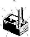
- FIG 1 shows a perspective view of a ventilation device according to the invention (1).
- the ventilation device (1) is integrated into a housing (2) which, in an advantageous embodiment, is made of impact-resistant plastic.
- Connection devices are arranged in the right-hand area of the upper side of the housing of the ventilation device (1).
- the ventilation device (1) has a ventilation hose (3), an oxygen hose and a measuring hose system (4) and a pressure connection (5) for an oxygen source.
- the ventilation device (1) has a display (6) and an operating element (7) designed as a rotary knob as user interfaces.
- An air inlet (8) is arranged in a lower area on the right side of the housing (2) of the ventilation device (1) and an air outlet (9) is arranged in a lower area on the front side of the housing (2).
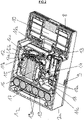
- FIG 2 a perspective view of a ventilation device (1) according to the invention with multiple horizontal sections is shown.
- the air inlet (8) can be seen on the right-hand side in a lower housing part (2a) of the ventilation device (1).
- the ambient air can be sucked in from the air inlet (8) by a fan (12) through a filter (10), particularly advantageously designed as a hygiene filter, via a suction area (11).
- the fan (12) is advantageously designed as a radial fan and has a fan wheel (12a), a fan shaft (12b) and a fan cap (12c) which encloses the fan wheel (12a) and the fan shaft (12b).
- the fan (12) On the side of the intake area (11a), the fan (12) is mounted in a first bearing element (13), which according to the invention is at least partially made of silicone.
- the first bearing element (13) creates a seal between the suction area (11a) and a first overpressure area (11b), into which the air enters through an opening in the fan cap (12c).
- This first overpressure area (11b) is spatially delimited by a housing structure and a second bearing element (14) and encloses the heat sink (15) of the fan (12).
- a blower motor (16), which drives the blower shaft (12b), is integrated in the center of the heat sink (15).
- the second bearing element (14) supports the heat sink (15) and the fan (12) connected to it in the housing (2) and is made at least partially of silicone, so that shocks and structure-borne noise are dampened.
- an outflow opening (17) is arranged in the second bearing element (14) in such a way that, in addition to the bearing of the fan (12), the air is forced to flow, so that the air within the first overpressure region (11b) can flow via the cooling fins of the heat sink ( 15) before it flows through the outflow opening (17) in the second bearing element (14) into a second overpressure region (11c).
- a cooling screen (18) which has two cylindrical tubes (18a) which lead to the air outlet (9) of the ventilation device (1) via a non-return valve.
- An energy storage element (19) is arranged in the left-hand area of the lower housing part (2a), which is designed as an accumulator and has six cells (19a) in the illustrated embodiment.
- figure 3 shows a perspective view of a vertical section of a ventilation device (1) according to the invention. Can be seen in addition to figure 3 in particular the different pressure areas (11) in the area of the blower (12).
- the intake area (11a) is in the area adjoining the blower (12) on the right and is delimited and sealed off from the first overpressure area (11b) with the aid of the first bearing element (13).
- the air reaches the first overpressure area (11b) through the action of the blower (12), which sucks it out of the intake area (11a) and presses it into the first overpressure area (11b).
- the bearing element (14) separates the first overpressure area (11b) from the second overpressure area (11c) and forces the air from the first overpressure area (11b) into the second overpressure area (11c) in such a way that the air flows along the heat sink (15) flows and a heat exchange between air and heat sink (15) takes place.
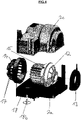
- FIG 4 the essential elements are shown in perspective to illustrate the guide structures in the area of the fan (12).
- the fan (12) is connected to the associated heat sink (15).
- the first bearing element (13), in which the fan can be mounted in the area of the suction opening, is shown to the right of the fan (12).
- the first bearing element (13) On its inside, the first bearing element (13) has a counter-structure adapted to the shape of the fan (12) in the area of the suction opening.
- the first bearing element (13) On its outside, has a radially circumferential groove with which the first bearing element (13) can be inserted into a correspondingly spring-like counterstructure in the housing (2) of the ventilation device (1).
- the second bearing element (14), which supports the fan (12) in the region of the heat sink (15), is arranged to the left of the heat sink (15).
- the second bearing element (14) On the side facing the heat sink (15), the second bearing element (14) has a reinforced bead which can be inserted into a corresponding counter-structure in the housing (2).
- the outflow opening (17) of the second bearing element (14) is implemented as an arrangement of a plurality of smaller openings, the size and position of which are adapted to the structure of the heat sink (15).
- a non-return membrane (18b) in the area of the cooling screen (18) which is shown with the cylindrical Tubes (18a) and the local structure of the lower housing part (2a) implement the non-return valve, so that no air can enter the ventilation device (1) in the area of the air outlet (8).
- the blower (2) is enclosed within the housing (2) of the ventilation device (1) by a hood (2c).
- figure 5 shows a sectional view of the in figure 4 illustrated elements of the inventive device for ventilation (1).
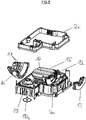
- figure 6 is a multi-sectional perspective view of the in the figures 4 and 5 elements shown in the region of the fan (12) of a ventilation device according to the invention from a different perspective.
Landscapes
- Health & Medical Sciences (AREA)
- Engineering & Computer Science (AREA)
- Life Sciences & Earth Sciences (AREA)
- Veterinary Medicine (AREA)
- Public Health (AREA)
- General Health & Medical Sciences (AREA)
- Pulmonology (AREA)
- Animal Behavior & Ethology (AREA)
- Biomedical Technology (AREA)
- Heart & Thoracic Surgery (AREA)
- Anesthesiology (AREA)
- Hematology (AREA)
- Emergency Medicine (AREA)
- Physics & Mathematics (AREA)
- General Engineering & Computer Science (AREA)
- Mechanical Engineering (AREA)
- Surgery (AREA)
- Biophysics (AREA)
- Pathology (AREA)
- Medical Informatics (AREA)
- Molecular Biology (AREA)
- Physiology (AREA)
- Fluid Mechanics (AREA)
- General Physics & Mathematics (AREA)
- Thermal Sciences (AREA)
- Measurement Of The Respiration, Hearing Ability, Form, And Blood Characteristics Of Living Organisms (AREA)
- Measuring Volume Flow (AREA)
- Cooling Or The Like Of Electrical Apparatus (AREA)
- Structures Of Non-Positive Displacement Pumps (AREA)
- Respiratory Apparatuses And Protective Means (AREA)
- Percussion Or Vibration Massage (AREA)
Description
- Die Erfindung betrifft eine Vorrichtung zur Beatmung sowie eines nichttherapeutischen Verfahrens zum Betrieb der Vorrichtung zur Beatmung.
- Insbesondere ist an eine Anwendung bei mobilen Notfallbeatmungsgeräten gedacht.
- Im Falle unzureichender oder ausbleibender eigenständiger Atmung eines sauerstoffbedürftigen Lebewesens, muss die Atemarbeit als lebenserhaltende Maßnahme von einem Dritten entweder manuell, beispielsweise durch Mund-zu-Mund-Beatmung oder mithilfe von Beatmungsbeuteln, oder maschinell mit einem Beatmungsgerät durchgeführt werden, um den Gasaustausch in der Lunge sicherzustellen und so die Organe mit Sauerstoff zu versorgen sowie CO2 abzuatmen.
- Eine sichere Methode ist nach dem Stand der Technik die maschinelle Beatmung, die in Form von Beatmungsgeräten zur medizintechnischen Ausstattung von Rettungskräften und Klinikpersonal gehört.
- Moderne Beatmungsgeräte und -verfahren bieten mit einer Volumen- und/oder Drucckontrolle wichtige Funktionen zu einer effektiven und gleichzeitig schonenden Beatmung von Patienten. Ein zu hoher Druck kann das Lungengewebe schädigen, während ein zu kleines Beatmungsvolumen eine Unterversorgung mit Sauerstoff zur Folge hat. Auch die Frequenz der Beatmung ist mit bekannten Beatmungsgeräten präzise an internationale Richtlinien anpassbar, die eine effektive Beatmung, auch im Falle von Wiederbelebungsmaßnahmen, gewährleisten sollen.
- Im Fall mobiler Beatmungsgeräte sind diese bei der Verwendung häufig Stößen, beispielsweise verursacht durch ein unsanftes Abstellen, Verladen oder durch Stürze, ausgesetzt. Die bei Stößen plötzlich auftretenden Kräfte können innerhalb eines Beatmungsgerätes auch an kritischen Orten auftreten, die durch diese plötzlich auftretenden Kräfte ggf. beschädigt werden können. Ein kritischer Ort ist beispielsweise das Gebläse, insbesondere das Lager und die Welle des Gebläses, die durch Querkräfte beschädigt werden können.
- Weiterhin erzeugen die Gebläse von bekannten Vorrichtungen zur Beatmung häufig Körperschall und in Verbindung mit den Leitstrukturen der Vorrichtungen zur Beatmung turbulente Strömungen, die einerseits Schallemissionen und Vibrationen der Vorrichtung zur Beatmung zur Folge haben können und andererseits die häufig eingesetzte Volumenstrommessung des Atemgases negativ beeinflussen.
- Gemäß dem Stand der Technik wird die Kühlluft von mobilen Beatmungsgeräten zum Abführen von Wärme nur während der Beatmung eines Patienten abgeblasen. Dies führt in einigen Fällen dazu, dass das Beatmungsgerät in einem eingeschalteten Zustand nicht ausreichend entwärmt wird und Schäden an Komponenten entstehen oder zumindest die Lebensdauer einzelner Komponenten verkürzt wird.
- Aus der
WO 2013/133 889 A1 ist bereits eine Vorrichtung zur Beatmung mit einem Lagerelement für ein Gebläse bekannt. - Ähnliche Vorrichtungen werden auch in der
US 7 975 688 B1 sowie derWO 2007/024955 A2 beschrieben. - In der
DE 20 2014 00 7024 U1 wird bereits eine Vorrichtung zur Beatmung beschrieben, die ein Gebläse mit einem Gebläsemotor aufweist und bei der der Gebläsemotor mit einem Lüfterrad versehen ist, und bei der zur Lagerung ein Lagerelement aus Silikon verwendet wird. - In der
WO 2013/1143 45 A1 wird ebenfalls bereits eine Vorrichtung zur Beatmung beschrieben, die ein von einem Gebläsemotor angetriebenes Gebläse aufweist. Der Gebläsemotor wird von Lagerelementen gelagert. Die Lagerelemente können aus Silikon gefertigt sein und es ist eine Kühlung des Gebläsemotors unter Verwendung von Kühlluft vorgesehen. - Eine Aufgabe der Erfindung ist es, das Gebläse der Vorrichtung zur Beatmung unempfindlicher gegenüber Stößen zu machen.
- Diese Aufgabe wird erfindungsgemäß durch die Merkmale von Patentanspruch 1 gelöst.
- Eine weitere Aufgabe der Erfindung ist es, den störenden Einfluss des Gebläses auf die Volumenstrommessung der Vorrichtung zur Beatmung zu reduzieren.
- Diese Aufgabe wird erfindungsgemäß ebenfalls durch die Merkmale von Patentanspruch 1 gelöst.
- Eine weitere Aufgabe der Erfindung ist es, die Vorrichtung zur Beatmung in einem eingeschalteten Zustand permanent durch das Abblasen der Kühlluft zu entwärmen.
- Diese Aufgabe wird erfindungsgemäß dadurch gelöst, dass das Gebläse auch in einem eingeschalteten Zustand der Vorrichtung zur Beatmung läuft, in dem keine Beatmung stattfindet.
- Eine erfindungsgemäße Ausführungsform einer Vorrichtung zur Beatmung weist zumindest ein Gebläse auf, über das die Umgebungsluft über einen Filter in eine Gebläsekammer innerhalb des Gehäuses der Vorrichtung zur Beatmung ansaugbar ist. Das Gebläse ist als ein Gebläsemodul realisiert, das neben einem Lüfterrad zumindest einen Kühlkörper und einen Gebläsemotor aufweist. Das Gebläsemodul ist erfindungsgemäß mit mindestens einem Silikonteil zumindest an zwei Enden gelagert, sodass Emissionen und Immissionen, insbesondere im Sinne von Körperschall bzw. Vibrationen und Stößen, von bzw. auf das Gebläsemodul dämpfbar sind.
- In einer vorteilhaften Ausführungsform der Erfindung ist das Gebläsemodul mithilfe von zwei Silikonteilen im Gehäuse gelagert, die als ein erstes Lagerelement und ein zweites Lagerelement ausgebildet sind.
- Der das Gebläsemodul im Bereich des Kühlkörpers lagernde Bereich des Silikonteils bzw. das entsprechende Lagerelement weist mindestens eine Ausströmöffnung auf und ist weiterhin als eine Leitstruktur für Luft derart ausgebildet, dass die von dem Gebläse in die Gebläsekammer gedrückte Luft über den Kühlkörper zwangsleitbar ist, um einen effektiven Wärmeaustausch zu realisieren.
- Die Kühlluft ist über eine Kühlblende aus dem Gehäuse abblasbar, die mindestens einen Auslass aufweist. Durch den Durchmesser des Auslasses bzw. der Auslässe in Verbindung mit dem Innendruck im Bereich der Kühlblende und der Rückstellkraft eines im Bereich des Auslasses angeordneten Rückschlagventils, ist der Volumenstrom der austretenden Kühlluft einstellbar.
- In einer vorteilhaften Ausführungsform weist die erfindungsgemäße Vorrichtung zur Beatmung eine Kühlblende mit zwei als zylinderförmige Röhren ausgebildeten Auslässen auf, die einen Durchmesser von 1,5 mm bis 3,5 mm aufweisen und mit denen ein Kühlluftstrom zwischen 25 l/min und 75 l/min realisierbar ist.
- In einer besonders vorteilhaften Ausführungsform der Erfindung weist die erfindungsgemäße Vorrichtung zur Beatmung eine Kühlblende mit zwei als zylinderförmige Röhren ausgebildeten Auslässen auf, die einen Durchmesser von 2 mm bis 3 mm aufweisen und mit denen ein Kühlluftstrom von etwa 50 l/min realisierbar ist.
- In einer vorteilhaften Ausführungsform eines erfindungsgemäßen nichttherapeutischen Verfahrens zum Betrieb der Vorrichtung zur Beatmung strömt die Umgebungsluft über einen Hygienefilter in das Gerät ein. Von dort gelangt sie in den Ansaugbereich der Gebläsekammer, wird vom Gebläse angesaugt und über eine Öffnung in der Gebläsekappe in den Druckbereich der Gebläsekammer geblasen. Von hier strömt die Luft, zwangsgeführt durch das zumindest teilweise aus Silikon gefertigte Lagerelement des Gebläses, über die erfindungsgemäßen Kühlrippen des Kühlkörpers des Gebläses zum Kühlventil hin. Das Silikonteil erfüllt dabei eine doppelte Funktion: zum einen dient es als Dämpfer gegenüber Schock- und Vibration, bzw. Sturz des Geräts, zum anderen dient es als Zwangsführung für die Luft, die über die Kühlrippen des Kühlkörpers die Wärme des Gebläses abtransportiert.
- In einer besonders vorteilhaften Ausführungsform des erfindungsgemäßen nichttherapeutischen Verfahrens zum Betrieb der Vorrichtung zur Beatmung wird die am Kühlkörper des Gebläses aufgenommene Wärme permanent nach außen abgeführt, auch bei fehlender Atemgasabgabe an einen Patienten.
- Weiterhin ist in einer vorteilhaften Ausführungsform einer erfindungsgemäßen Vorrichtung zur Beatmung das die Leitstruktur für die Luft im Überdruckbereich realisierende Lagerelement derart ausgebildet, dass der Luftstrom beruhigt wird, sodass ein störender Einfluss auf eine im Bereich der erfindungsgemäßen Vorrichtung durchgeführte Volumenstrommessung vermindert wird. Dies ist erfindungsgemäß beispielsweise dadurch realisiert, dass das Lagerelement im Bereich des Kühlkörpers des Gebläses mehrere gleichartig ausgebildete Ausströmöffnungen aufweist, die den Luftstrom in Verbindung mit der Struktur des Kühlkörpers beruhigen.
- Im Bereich des Kühlkörpers ist das Silikonteil bzw. das entsprechende Lagerelement in einer vorteilhaften Ausführungsform der Erfindung überzieherartig ausgebildet, sodass es ähnlich einer Hülse zumindest bereichsweise über den Kühlkörper des Gebläses stülpbar ist und diesen radial umlaufend umschließt.
- Zusätzlich zur gedämpften Lagerung des Gebläses realisiert das Silikonteil bzw. realisieren die Lagerelemente in einer vorteilhaften Ausführungsform der Erfindung eine Abdichtung der verschiedenen Druckbereiche in der Umgebung des Gebläses voneinander. Die Abdichtung wird durch die Struktur des Silikonteils bzw. der Lagerelemente in Verbindung mit der Struktur des das Gebläse umgebenden Gehäuses beispielsweise derart realisiert, dass das Silikonteil bzw. das Lagerelement im Bereich der Ansaugöffnung des Gebläses diesen von einem ersten Überdruckbereich im Bereich des Kühlkörpers des Gebläses durch eine nut- und federartig ausgebildete Struktur abdichtet.
- Verschiedene Ausführungsbeispiele und Ausgestaltungen der Erfindung sind in den nachfolgenden Figuren abgebildet. Es zeigen
- Figur 1:
- eine perspektivische Darstellung einer erfindungsgemäßen Vorrichtung zur Beatmung,
- Figur 2:
- einen horizontalen Schnitt einer erfindungsgemäßen Vorrichtung zur Beatmung, aufweisend eine stoßgedämpfte Gebläselagerung,
- Figur 3:
- einen vertikalen Schnitt einer erfindungsgemäßen Vorrichtung zur Beatmung, aufweisend eine stoßgedämpfte Gebläselagerung,
- Figur 4:
- eine perspektivische Ansicht eines erfindungsgemäßen Gebläsemoduls einer Vorrichtung zur Beatmung,
- Figur 5:
- einen horizontalen Schnitt einer Explosionsdarstellung eines erfindungsgemäßen Gebläsemoduls und
- Figur 6:
- eine mehrfach geschnittene perspektivische Ansicht eines erfindungsgemäßen Gebläsemoduls einer Vorrichtung zur Beatmung.
-
Figur 1 zeigt eine perspektivische Darstellung einer erfindungsgemäßen Vorrichtung zur Beatmung (1). Die Vorrichtung zur Beatmung (1) ist in ein Gehäuse (2) integriert, das in einer vorteilhaften Ausführungsform aus einem stoßfesten Kunststoff gefertigt ist. Im rechten Bereich der Gehäuseoberseite der Vorrichtung zur Beatmung (1) sind Anschlussvorrichtungen angeordnet. - In der dargestellten Ausführungsform weist die Vorrichtung zur Beatmung (1) einen Beatmungsschlauch (3), einen Sauerstoffschlauch und ein Messschlauchsystem (4) sowie einen Druckanschluss (5) für eine Sauerstoffquelle auf.
- Als Benutzerschnittstellen weist die Vorrichtung zur Beatmung (1) ein Display (6) und ein als ein Drehknopf ausgebildetes Bedienelement (7) auf.
- Auf der rechten Seite des Gehäuses (2) der Vorrichtung zur Beatmung (1) ist in einem unteren Bereich ein Lufteinlass (8) angeordnet und auf der Vorderseite des Gehäuses (2) ist in einem unteren Bereich ein Luftauslass (9) angeordnet.
- In
Figur 2 ist eine mehrfach horizontal geschnittene perspektivische Ansicht einer erfindungsgemäßen Vorrichtung zur Beatmung (1) dargestellt. In ein Gehäuseunterteil (2a) der Vorrichtung zur Beatmung (1) ist auf der rechten Seite der Lufteinlass (8) zu erkennen. Von dem Lufteinlass (8) ist die Umgebungsluft durch einen Filter (10), besonders vorteilhaft ausgebildet als ein Hygienefilter, über einen Ansaugbereich (11) von einem Gebläse (12) ansaugbar. - Das Gebläse (12), ist vorteilhaft als ein Radialgebläse ausgebildet und weist ein Lüfterrad (12a), eine Gebläsewelle (12b) und eine Gebläsekappe (12c) auf, die das Lüfterrad (12a) und die Gebläsewelle (12b) umschließt.
- Auf der Seite des Ansaugbereiches (11a) ist das Gebläse (12) in einem ersten Lagerelement (13) gelagert, das erfindungsgemäß zumindest teilweise aus Silikon gefertigt ist. Zudem realisiert das erste Lagerelement (13) eine Dichtung zwischen Ansaugbereich (11a) und einem ersten Überdruckbereich (11b), in den die Luft durch eine Öffnung in der Gebläsekappe (12c) gelangt.
- Dieser erste Überdruckbereich (11b) ist durch eine Gehäusestruktur und ein zweites Lagerelement (14) räumlich begrenzt und umschließt den Kühlkörper (15) des Gebläses (12). Mittig in den Kühlkörper (15) ist ein Gebläsemotor (16) integriert, der die Gebläsewelle (12b) antreibt. Das zweite Lagerelement (14) lagert den Kühlkörper (15) und das damit verbundene Gebläse (12) im Gehäuse (2) und ist erfindungsgemäß zumindest teilweise aus Silikon gefertigt, sodass Stöße und Körperschall gedämpft werden. Zusätzlich ist eine Ausströmöffnung (17) derart in dem zweiten Lagerelement (14) angeordnet, dass zusätzlich zu der Lagerung des Gebläses (12) eine Zwangsführung der Luft realisiert ist, sodass die Luft innerhalb des ersten Überdruckbereiches (11b) über die Kühlrippen des Kühlkörpers (15) strömt, bevor diese durch die Ausströmöffnung (17) im zweiten Lagerelement (14) in einen zweiten Überdruckbereich (11c) strömt.
- Im Bereich des zweiten Überdruckbereiches (11c) ist eine Kühlblende (18) angeordnet, die zwei zylinderförmige Röhren (18a) aufweist, die über ein Rückschlagventil zum Luftauslass (9) der Vorrichtung zur Beatmung (1) führen.
- Im linken Bereich des Gehäuseunterteils (2a) ist ein Energiespeicherelement (19) angeordnet, dass als ein Akkumulator ausgebildet ist und in der dargestellten Ausführungsform sechs Zellen (19a) aufweist.
-
Figur 3 zeigt eine perspektivische Ansicht eines vertikalen Schnittes einer erfindungsgemäßen Vorrichtung zur Beatmung (1). Zu erkennen sind ergänzend zuFigur 3 insbesondere die verschiedenen Druckbereiche (11) im Bereich des Gebläses (12). - Der Ansaugbereich (11a) liegt in dem rechts an das Gebläse (12) angrenzenden Bereich und ist mithilfe des ersten Lagerelementes (13) von dem ersten Überdruckbereich (11b) abgegrenzt und abgedichtet. In den ersten Überdruckbereich (11b) gelangt die Luft durch die Wirkung des Gebläses (12), dass diese aus dem Ansaugbereich (11a) absaugt und in den ersten Überdruckbereich (11b) hineindrückt.
- Das Lagerelement (14) trennt den ersten Überdruckbereich (11b) von dem zweiten Überdruckbereich (11c) und realisiert eine Zwangsführung der Luft von dem ersten Überdruckbereich (11b) in den zweiten Überdruckbereich (11c) derart, dass die Luft entlang des Kühlkörpers (15) strömt und ein Wärmeaustausch zwischen Luft und Kühlkörper (15) stattfindet.
- In
Figur 4 sind die wesentlichen Elemente zur Veranschaulichung der Leitstrukturen im Bereich des Gebläses (12) perspektivisch dargestellt. Das Gebläse (12) ist mit dem zugeordneten Kühlkörper (15) verbunden. Rechts neben dem Gebläse (12) ist das erste Lagerelement (13) dargestellt, in dem das Gebläse im Bereich der Ansaugöffnung lagerbar ist. An seiner Innenseite weist das erste Lagerelement (13) eine an die Form des Gebläses (12) im Bereich der Ansaugöffnung angepasste Gegenstruktur auf. An seiner Außenseite weist das erste Lagerelement (13) eine radial umlaufende Nut auf, mit der das erste Lagerelement (13) in eine entsprechend federartig ausgebildete Gegenstruktur im Gehäuse (2) der Vorrichtung zur Beatmung (1) einsetzbar ist. - Links neben dem Kühlkörper (15) ist das zweite Lagerelement (14) angeordnet, welches das Gebläse (12) im Bereich des Kühlkörpers (15) lagert. Auf der dem Kühlkörper (15) zugewandten Seite weist das zweite Lagerelement (14) einen verstärkten Wulst auf, der in eine entsprechende Gegenstruktur im Gehäuse (2) einsetzbar ist. Weiterhin ist die Ausströmöffnung (17) des zweiten Lagerelementes (14) als eine Anordnung mehrerer kleinerer Öffnungen realisiert, die in ihrer Größe und Position der Struktur des Kühlkörpers (15) angepasst sind.
- Unterhalb des dargestellten Ausschnittes des Gehäuseunterteils (2a) ist im Bereich der Kühlblende (18) eine Rückschlagmembran (18b) gezeigt, die mit den zylinderförmigen Röhren (18a) und der lokalen Struktur des Gehäuseunterteils (2a) das Rückschlagventil realisieren, sodass im Bereich des Luftauslasses (8) keine Luft in die Vorrichtung zur Beatmung (1) eintreten kann.
- Innerhalb des Gehäuses (2) der Vorrichtung zur Beatmung (1) ist das Gebläse (2) durch eine Haube (2c) eingefasst.
-
Figur 5 zeigt eine geschnittene Teildarstellung der inFigur 4 dargestellten Elemente der erfindungsgemäßen Vorrichtung zur Beatmung (1). - In
Figur 6 ist eine mehrfach geschnittene perspektivische Darstellung der in denFiguren 4 und5 gezeigten Elementen im Bereich des Gebläses (12) einer erfindungsgemäßen Vorrichtung zur Beatmung in einem anderen Blickwinkel dargestellt.
Claims (8)
- Vorrichtung zur Beatmung (1), die mindestens ein Gebläse (12) samt Kühlrippen aufweist, das von einem Gebläsemotor (16) angetrieben wird, und bei der zumindest der Gebläsemotor (16) auf mindestens einem Lagerelement (14) gelagert ist und dass das Lagerelement (14) eine Leitstruktur aufweist, die mithilfe des Gebläses (12) bewegte Kühlluft über die Kühlrippen des Kühlkörpers (15) des Gebläsemotors (16) zwangsführt, wobei das Lagerelement (14) aus Silikon gefertigt ist und wobei das Lagerelement (14) die Leitstruktur für die Kühlluft derart realisiert, dass die Kühlluft angepasst an den Aufbau des Kühlkörpers (15) geleitet wird und dass das Lagerelement (14) über den Kühlkörper (15) stülpbar ist und den Kühlkörper (15) radial umlaufend umschließt.
- Vorrichtung nach Anspruch 1, dadurch gekennzeichnet, dass diese zwei Lagerelemente (13, 14) aufweist, von denen ein erstes Lagerelement (13) das Gebläse (12) auf der Seite des Ansaugbereiches (11a) lagert und das zweite Lagerelement (14) das Gebläse (12) im Bereich des Kühlkörpers (15) lagert.
- Vorrichtung nach mindestens einem der vorstehenden Ansprüche, dadurch gekennzeichnet, dass diese ein Gebläsemodul aufweist, welches zumindest den Kühlkörper (15), den Gebläsemotor (16), ein Lüfterrad (12a), eine Gebläsewelle (12b) und eine Gebläsehaube (12c) aufweist, und dass das Gebläsemodul durch die zwei Lagerelemente (13, 14) aus Silikon in der Vorrichtung zur Beatmung (1) gelagert ist.
- Vorrichtung nach mindestens einem der vorstehenden Ansprüche, dadurch gekennzeichnet, dass mindestens eines der Lagerelemente (13, 14) verschiedene Druckbereiche voneinander trennt und abdichtet.
- Vorrichtung nach mindestens einem der vorstehenden Ansprüche, dadurch gekennzeichnet, dass diese als ein Notfallbeatmungsgerät ausgebildet ist.
- Vorrichtung nach Anspruch 6, dadurch gekennzeichnet, dass diese als ein mobiles Notfallbeatmungsgerät ausgebildet ist.
- Nicht-therapeutisches Verfahren zum Betrieb der Vorrichtung zur Beatmung gemäß einem der Ansprüche 1 bis 6, bei der das mindestens eine Gebläse (12) samt Kühlrippen verwendet wird, von dem zumindest der Gebläsemotor (16) auf mindestens einem Lagerelement (13, 14) gelagert ist, und bei dem in einem eingeschalteten Zustand der Vorrichtung zur Beatmung (1) permanent Kühlluft abgeblasen wird.
- Nicht-therapeutisches Verfahren nach Anspruch 7, dadurch gekennzeichnet, dass Kühlluft mit einem permanenten Volumenstrom von 25 l/min bis 75 l/min abgeblasen wird.
Applications Claiming Priority (2)
| Application Number | Priority Date | Filing Date | Title |
|---|---|---|---|
| DE102017001558 | 2017-02-20 | ||
| PCT/DE2018/000043 WO2018149436A1 (de) | 2017-02-20 | 2018-02-16 | Vorrichtung zur beatmung mit differenzdrucksensor |
Publications (2)
| Publication Number | Publication Date |
|---|---|
| EP3582841A1 EP3582841A1 (de) | 2019-12-25 |
| EP3582841B1 true EP3582841B1 (de) | 2022-06-29 |
Family
ID=61616732
Family Applications (2)
| Application Number | Title | Priority Date | Filing Date |
|---|---|---|---|
| EP18709915.5A Active EP3582840B1 (de) | 2017-02-20 | 2018-02-16 | Vorrichtung zur beatmung mit differenzdrucksensor |
| EP18712072.0A Active EP3582841B1 (de) | 2017-02-20 | 2018-02-16 | Vorrichtung zur beatmung mit einem gebläse-lagerelement und leitstruktur |
Family Applications Before (1)
| Application Number | Title | Priority Date | Filing Date |
|---|---|---|---|
| EP18709915.5A Active EP3582840B1 (de) | 2017-02-20 | 2018-02-16 | Vorrichtung zur beatmung mit differenzdrucksensor |
Country Status (7)
| Country | Link |
|---|---|
| US (2) | US11311689B2 (de) |
| EP (2) | EP3582840B1 (de) |
| CN (2) | CN110392589B (de) |
| DE (4) | DE112018000912A5 (de) |
| ES (1) | ES2899182T3 (de) |
| RU (2) | RU2734462C1 (de) |
| WO (2) | WO2018149436A1 (de) |
Families Citing this family (10)
| Publication number | Priority date | Publication date | Assignee | Title |
|---|---|---|---|---|
| USD790683S1 (en) * | 2015-03-11 | 2017-06-27 | Resmed Limited | Pressurized air delivery console |
| USD917039S1 (en) * | 2018-02-01 | 2021-04-20 | Resvent Medical Technology Co., Ltd | Positive airway pressure assembly |
| FR3110678B1 (fr) * | 2020-05-20 | 2022-08-26 | Renault Sas | Dispositif de refroidissement et d’assemblage d’un module de ventilation destiné à un dispositif d’assistance à la respiration |
| DE102020118466A1 (de) * | 2020-07-13 | 2022-01-13 | Hamilton Medical Ag | Notfall-Beatmungsgerät mit konduktiv und konvektiv gekühltem Gebläse |
| DE102020118467A1 (de) * | 2020-07-13 | 2022-01-13 | Hamilton Medical Ag | Notfall-Beatmungsgerät mit abnehmbarem gemeinsamen Deckel zur gleichzeitigen Abdeckung von Filter- und Batteriefach |
| JP7723089B2 (ja) * | 2020-11-03 | 2025-08-13 | レスメド・プロプライエタリー・リミテッド | 呼吸圧力治療デバイス |
| CN119607347B (zh) * | 2020-12-31 | 2026-06-23 | 深圳迈瑞动物医疗科技股份有限公司 | 麻醉机及兽用麻醉机 |
| US11896857B2 (en) * | 2021-01-14 | 2024-02-13 | Ford Global Technologies, Llc | Personal air purifying respirator |
| RU2761410C1 (ru) * | 2021-04-28 | 2021-12-08 | Общество с ограниченной ответственностью "Эм Энд Ти Прод" | Маска лицевая для неинвазивной искусственной вентиляции легких |
| DE102024105742A1 (de) * | 2024-02-29 | 2025-09-04 | Weinmann Emergency Medical Technology Gmbh + Co. Kg | Beatmungsgerät mit Kühlvorrichtung |
Citations (2)
| Publication number | Priority date | Publication date | Assignee | Title |
|---|---|---|---|---|
| WO2013114345A1 (en) * | 2012-02-02 | 2013-08-08 | Imt Ag | Sound-proofing housing for a respirator |
| DE202014007024U1 (de) * | 2014-03-28 | 2014-11-12 | Weinmann Geräte für Medizin GmbH + Co. KG | Vorrichtung zur Beatmung |
Family Cites Families (28)
| Publication number | Priority date | Publication date | Assignee | Title |
|---|---|---|---|---|
| US4403514A (en) | 1980-05-20 | 1983-09-13 | Critikon, Inc. | Pneumotachograph with pitot-like tubes |
| US4859858A (en) * | 1986-12-04 | 1989-08-22 | Cascadia Technology Corporation | Gas analyzers |
| EP0331772A1 (de) * | 1988-03-08 | 1989-09-13 | Dräger Nederland B.V. | Differenzdruckmesser für bidirektionale Gasströme |
| CA2086962A1 (en) * | 1992-01-21 | 1993-07-22 | Dee J. Neville | Sidestream flow sensor for spirometry |
| US5535633A (en) * | 1992-09-23 | 1996-07-16 | Korr Medical Technologies, Inc. | Differential pressure sensor for respiratory monitoring |
| US5347843A (en) * | 1992-09-23 | 1994-09-20 | Korr Medical Technologies Inc. | Differential pressure flowmeter with enhanced signal processing for respiratory flow measurement |
| US5379650A (en) * | 1992-09-23 | 1995-01-10 | Korr Medical Technologies Inc. | Differential pressure sensor for respiratory monitoring |
| US6244821B1 (en) * | 1999-02-19 | 2001-06-12 | Mechanization Systems Company, Inc. | Low speed cooling fan |
| DE10035938A1 (de) * | 1999-07-23 | 2001-02-22 | Metrax Gmbh | Beatmungsgerät |
| CN1300556C (zh) * | 2002-08-01 | 2007-02-14 | 湿王株式会社 | 节流式流量计 |
| US7975688B1 (en) * | 2003-03-14 | 2011-07-12 | Ric Investments, Llc | Vibration reducing blower assembly mounting |
| EP1621773B1 (de) * | 2004-07-30 | 2013-04-17 | Brose Fahrzeugteile GmbH & Co. KG, Würzburg | Kühlgebläse mit Elektromotor |
| DK3542869T3 (da) | 2004-08-27 | 2021-04-12 | Univ Johns Hopkins | Engangssøvn- og åndedrætsmonitor |
| US7617823B2 (en) * | 2005-08-24 | 2009-11-17 | Ric Investments, Llc | Blower mounting assembly |
| CN103185027B (zh) * | 2005-10-28 | 2017-12-05 | 瑞思迈发动机及马达技术股份有限公司 | 单级或多级鼓风机以及该鼓风机用嵌套式蜗壳和/或叶轮 |
| NZ577485A (en) * | 2006-05-24 | 2011-01-28 | Resmed Ltd | Compact low noise efficient blower for CPAP devices with a shield to prevent a line-of-sight path within |
| US7997272B2 (en) * | 2006-09-11 | 2011-08-16 | Ric Investments, Llc. | Ventilating apparatus and method enabling a patient to talk with or without a trachostomy tube check valve |
| CN101311683A (zh) * | 2007-12-29 | 2008-11-26 | 北京谊安医疗系统股份有限公司 | 呼吸机及其低差压式流量检测机构 |
| US20100059055A1 (en) * | 2008-09-05 | 2010-03-11 | Brungart Timothy A | Gas delivery system including a flow generator having an isolated blower assembly for noise reduction |
| EP3251716B1 (de) * | 2009-08-11 | 2019-02-20 | ResMed Motor Technologies Inc | Ventilator mit einem einstufigen achsensymmetrischen gebläse |
| CN106075683B (zh) * | 2009-08-28 | 2019-02-19 | 瑞思迈有限公司 | Pap系统 |
| DE102010014873B4 (de) * | 2010-04-10 | 2016-05-19 | Drägerwerk AG & Co. KGaA | Beatmungsvorrichtung |
| NZ718377A (en) * | 2012-03-06 | 2017-11-24 | Resmed Motor Technologies Inc | Flow generator |
| US10125791B2 (en) * | 2014-11-17 | 2018-11-13 | Nidec Corporation | Blower |
| DE102014119146A1 (de) * | 2014-12-19 | 2016-06-23 | Fritz Stephan Gmbh Medizintechnik | Sensorvorrichtung für die maschinelle Beatmung |
| JP6382122B2 (ja) * | 2015-01-28 | 2018-08-29 | 日立アプライアンス株式会社 | 電動送風機及びそれを搭載した電気掃除機 |
| FR3035456A3 (fr) * | 2015-04-23 | 2016-10-28 | Air Liquide Medical Systems | Micro-soufflante pour ventilateur medical a duree de vie amelioree |
| EP3933207B1 (de) * | 2020-06-29 | 2025-11-26 | Dürr Dental SE | Medizinisches, insbesondere dentalmedizinisches, gebläse mit schallisolierendem dämmsystem |
-
2018
- 2018-02-16 US US16/485,559 patent/US11311689B2/en active Active
- 2018-02-16 ES ES18709915T patent/ES2899182T3/es active Active
- 2018-02-16 RU RU2019123412A patent/RU2734462C1/ru active
- 2018-02-16 DE DE112018000912.2T patent/DE112018000912A5/de not_active Withdrawn
- 2018-02-16 WO PCT/DE2018/000043 patent/WO2018149436A1/de not_active Ceased
- 2018-02-16 DE DE102018001331.7A patent/DE102018001331A1/de not_active Withdrawn
- 2018-02-16 RU RU2019129528A patent/RU2736215C1/ru active
- 2018-02-16 WO PCT/DE2018/000042 patent/WO2018149435A1/de not_active Ceased
- 2018-02-16 EP EP18709915.5A patent/EP3582840B1/de active Active
- 2018-02-16 US US16/485,537 patent/US11534564B2/en active Active
- 2018-02-16 CN CN201880012862.2A patent/CN110392589B/zh active Active
- 2018-02-16 DE DE112018000901.7T patent/DE112018000901A5/de not_active Withdrawn
- 2018-02-16 EP EP18712072.0A patent/EP3582841B1/de active Active
- 2018-02-16 CN CN201880012861.8A patent/CN110582317B/zh active Active
- 2018-02-16 DE DE102018001332.5A patent/DE102018001332A1/de not_active Withdrawn
Patent Citations (2)
| Publication number | Priority date | Publication date | Assignee | Title |
|---|---|---|---|---|
| WO2013114345A1 (en) * | 2012-02-02 | 2013-08-08 | Imt Ag | Sound-proofing housing for a respirator |
| DE202014007024U1 (de) * | 2014-03-28 | 2014-11-12 | Weinmann Geräte für Medizin GmbH + Co. KG | Vorrichtung zur Beatmung |
Also Published As
| Publication number | Publication date |
|---|---|
| CN110582317B (zh) | 2023-03-17 |
| ES2899182T3 (es) | 2022-03-10 |
| US20200046920A1 (en) | 2020-02-13 |
| DE102018001331A1 (de) | 2018-08-23 |
| DE112018000912A5 (de) | 2019-10-24 |
| CN110392589B (zh) | 2023-03-21 |
| WO2018149435A1 (de) | 2018-08-23 |
| US20190366025A1 (en) | 2019-12-05 |
| US11534564B2 (en) | 2022-12-27 |
| DE102018001332A1 (de) | 2018-08-23 |
| US11311689B2 (en) | 2022-04-26 |
| CN110392589A (zh) | 2019-10-29 |
| EP3582840B1 (de) | 2021-09-15 |
| EP3582841A1 (de) | 2019-12-25 |
| DE112018000901A5 (de) | 2019-10-24 |
| CN110582317A (zh) | 2019-12-17 |
| EP3582840A1 (de) | 2019-12-25 |
| WO2018149436A1 (de) | 2018-08-23 |
| RU2734462C1 (ru) | 2020-10-16 |
| RU2736215C1 (ru) | 2020-11-12 |
Similar Documents
| Publication | Publication Date | Title |
|---|---|---|
| DE102018001332A1 (de) | Verfahren und Vorrichtung zur Beatmung | |
| DE2612877C2 (de) | Atemluftversorgungsgerät | |
| EP3580770B1 (de) | Trockentransformator mit luftkühlung | |
| DE202011101554U1 (de) | Beatmungsgerät zum Identifizieren der Reinheit/Trübung eines Filters | |
| DE10253937B3 (de) | Lüftereinheiten für ein Beatmungsgerät | |
| DE69123961T2 (de) | Systemanordnung zum evakuieren von anästhesie- oder analgesiegas | |
| DE202020105775U1 (de) | Rohrfilter und System zur Filtration verschmutzter Umgebungsluft | |
| DE102019106703A1 (de) | Vorrichtung ausgebildet als Muschelkopfhörer oder als Gehörschutz mit integrierten Ventilatoren | |
| DE2938726A1 (de) | Filtrierende atemschutzmaske | |
| AT17890U1 (de) | Schutzhauben-Anordnung | |
| DE10226160B4 (de) | Luftbefeuchter für ein Beatmungsgerät | |
| DE102021001500A1 (de) | Atemschutzmaske mit aktiver Belüftung | |
| EP3292007B2 (de) | Kühlsystem eines gefechtsfahrzeugs sowie druckkaskade zur kühlung von mindestens einer elektroikeinheit in einem gefechtsfahrzeug mittels eines kühlsystems | |
| DE202015008332U1 (de) | Ansaugvorrichtung zur Nutzung von Bienenstockluft | |
| DE2943365C2 (de) | ||
| DE2916071A1 (de) | Verfahren und vorrichtung zur ableitung eines betaeubungsagenzes | |
| EP1442767B1 (de) | Einteiliger Personenschutzanzug | |
| WO2019233708A1 (de) | Atemschutzmaske und filtergehäuse für eine atemschutzmaske | |
| DE202017107041U1 (de) | Ausatemventil für Beatmungsgeräte | |
| DE102022129753A1 (de) | Kontaminationsvermeidung im gebläse von beatmungsgeräten | |
| DE202005008359U1 (de) | Tracheostomarohr mit Ventileinrichtung | |
| DE2910315C3 (de) | Kapselgehörschützer | |
| DE202021000878U1 (de) | Einrichtung zur Luftentkeimung von Räumen in Gebäuden | |
| DE20208663U1 (de) | Elektrische Atemschutzmaske | |
| DE102020114514A1 (de) | Atemschutzmaske mit austauschbaren Filterelementen |
Legal Events
| Date | Code | Title | Description |
|---|---|---|---|
| STAA | Information on the status of an ep patent application or granted ep patent |
Free format text: STATUS: UNKNOWN |
|
| STAA | Information on the status of an ep patent application or granted ep patent |
Free format text: STATUS: THE INTERNATIONAL PUBLICATION HAS BEEN MADE |
|
| PUAI | Public reference made under article 153(3) epc to a published international application that has entered the european phase |
Free format text: ORIGINAL CODE: 0009012 |
|
| STAA | Information on the status of an ep patent application or granted ep patent |
Free format text: STATUS: REQUEST FOR EXAMINATION WAS MADE |
|
| 17P | Request for examination filed |
Effective date: 20190617 |
|
| AK | Designated contracting states |
Kind code of ref document: A1 Designated state(s): AL AT BE BG CH CY CZ DE DK EE ES FI FR GB GR HR HU IE IS IT LI LT LU LV MC MK MT NL NO PL PT RO RS SE SI SK SM TR |
|
| AX | Request for extension of the european patent |
Extension state: BA ME |
|
| DAV | Request for validation of the european patent (deleted) | ||
| DAX | Request for extension of the european patent (deleted) | ||
| STAA | Information on the status of an ep patent application or granted ep patent |
Free format text: STATUS: EXAMINATION IS IN PROGRESS |
|
| 17Q | First examination report despatched |
Effective date: 20210318 |
|
| GRAP | Despatch of communication of intention to grant a patent |
Free format text: ORIGINAL CODE: EPIDOSNIGR1 |
|
| STAA | Information on the status of an ep patent application or granted ep patent |
Free format text: STATUS: GRANT OF PATENT IS INTENDED |
|
| INTG | Intention to grant announced |
Effective date: 20220211 |
|
| GRAS | Grant fee paid |
Free format text: ORIGINAL CODE: EPIDOSNIGR3 |
|
| GRAA | (expected) grant |
Free format text: ORIGINAL CODE: 0009210 |
|
| STAA | Information on the status of an ep patent application or granted ep patent |
Free format text: STATUS: THE PATENT HAS BEEN GRANTED |
|
| AK | Designated contracting states |
Kind code of ref document: B1 Designated state(s): AL AT BE BG CH CY CZ DE DK EE ES FI FR GB GR HR HU IE IS IT LI LT LU LV MC MK MT NL NO PL PT RO RS SE SI SK SM TR |
|
| REG | Reference to a national code |
Ref country code: CH Ref legal event code: EP |
|
| REG | Reference to a national code |
Ref country code: DE Ref legal event code: R096 Ref document number: 502018010041 Country of ref document: DE |
|
| REG | Reference to a national code |
Ref country code: AT Ref legal event code: REF Ref document number: 1500876 Country of ref document: AT Kind code of ref document: T Effective date: 20220715 |
|
| REG | Reference to a national code |
Ref country code: IE Ref legal event code: FG4D Free format text: LANGUAGE OF EP DOCUMENT: GERMAN |
|
| REG | Reference to a national code |
Ref country code: LT Ref legal event code: MG9D |
|
| PG25 | Lapsed in a contracting state [announced via postgrant information from national office to epo] |
Ref country code: SE Free format text: LAPSE BECAUSE OF FAILURE TO SUBMIT A TRANSLATION OF THE DESCRIPTION OR TO PAY THE FEE WITHIN THE PRESCRIBED TIME-LIMIT Effective date: 20220629 Ref country code: NO Free format text: LAPSE BECAUSE OF FAILURE TO SUBMIT A TRANSLATION OF THE DESCRIPTION OR TO PAY THE FEE WITHIN THE PRESCRIBED TIME-LIMIT Effective date: 20220929 Ref country code: LT Free format text: LAPSE BECAUSE OF FAILURE TO SUBMIT A TRANSLATION OF THE DESCRIPTION OR TO PAY THE FEE WITHIN THE PRESCRIBED TIME-LIMIT Effective date: 20220629 Ref country code: HR Free format text: LAPSE BECAUSE OF FAILURE TO SUBMIT A TRANSLATION OF THE DESCRIPTION OR TO PAY THE FEE WITHIN THE PRESCRIBED TIME-LIMIT Effective date: 20220629 Ref country code: GR Free format text: LAPSE BECAUSE OF FAILURE TO SUBMIT A TRANSLATION OF THE DESCRIPTION OR TO PAY THE FEE WITHIN THE PRESCRIBED TIME-LIMIT Effective date: 20220930 Ref country code: FI Free format text: LAPSE BECAUSE OF FAILURE TO SUBMIT A TRANSLATION OF THE DESCRIPTION OR TO PAY THE FEE WITHIN THE PRESCRIBED TIME-LIMIT Effective date: 20220629 Ref country code: BG Free format text: LAPSE BECAUSE OF FAILURE TO SUBMIT A TRANSLATION OF THE DESCRIPTION OR TO PAY THE FEE WITHIN THE PRESCRIBED TIME-LIMIT Effective date: 20220929 |
|
| REG | Reference to a national code |
Ref country code: NL Ref legal event code: MP Effective date: 20220629 |
|
| PG25 | Lapsed in a contracting state [announced via postgrant information from national office to epo] |
Ref country code: RS Free format text: LAPSE BECAUSE OF FAILURE TO SUBMIT A TRANSLATION OF THE DESCRIPTION OR TO PAY THE FEE WITHIN THE PRESCRIBED TIME-LIMIT Effective date: 20220629 Ref country code: LV Free format text: LAPSE BECAUSE OF FAILURE TO SUBMIT A TRANSLATION OF THE DESCRIPTION OR TO PAY THE FEE WITHIN THE PRESCRIBED TIME-LIMIT Effective date: 20220629 |
|
| PG25 | Lapsed in a contracting state [announced via postgrant information from national office to epo] |
Ref country code: NL Free format text: LAPSE BECAUSE OF FAILURE TO SUBMIT A TRANSLATION OF THE DESCRIPTION OR TO PAY THE FEE WITHIN THE PRESCRIBED TIME-LIMIT Effective date: 20220629 |
|
| PG25 | Lapsed in a contracting state [announced via postgrant information from national office to epo] |
Ref country code: SM Free format text: LAPSE BECAUSE OF FAILURE TO SUBMIT A TRANSLATION OF THE DESCRIPTION OR TO PAY THE FEE WITHIN THE PRESCRIBED TIME-LIMIT Effective date: 20220629 Ref country code: SK Free format text: LAPSE BECAUSE OF FAILURE TO SUBMIT A TRANSLATION OF THE DESCRIPTION OR TO PAY THE FEE WITHIN THE PRESCRIBED TIME-LIMIT Effective date: 20220629 Ref country code: RO Free format text: LAPSE BECAUSE OF FAILURE TO SUBMIT A TRANSLATION OF THE DESCRIPTION OR TO PAY THE FEE WITHIN THE PRESCRIBED TIME-LIMIT Effective date: 20220629 Ref country code: PT Free format text: LAPSE BECAUSE OF FAILURE TO SUBMIT A TRANSLATION OF THE DESCRIPTION OR TO PAY THE FEE WITHIN THE PRESCRIBED TIME-LIMIT Effective date: 20221031 Ref country code: ES Free format text: LAPSE BECAUSE OF FAILURE TO SUBMIT A TRANSLATION OF THE DESCRIPTION OR TO PAY THE FEE WITHIN THE PRESCRIBED TIME-LIMIT Effective date: 20220629 Ref country code: EE Free format text: LAPSE BECAUSE OF FAILURE TO SUBMIT A TRANSLATION OF THE DESCRIPTION OR TO PAY THE FEE WITHIN THE PRESCRIBED TIME-LIMIT Effective date: 20220629 |
|
| PG25 | Lapsed in a contracting state [announced via postgrant information from national office to epo] |
Ref country code: PL Free format text: LAPSE BECAUSE OF FAILURE TO SUBMIT A TRANSLATION OF THE DESCRIPTION OR TO PAY THE FEE WITHIN THE PRESCRIBED TIME-LIMIT Effective date: 20220629 Ref country code: IS Free format text: LAPSE BECAUSE OF FAILURE TO SUBMIT A TRANSLATION OF THE DESCRIPTION OR TO PAY THE FEE WITHIN THE PRESCRIBED TIME-LIMIT Effective date: 20221029 |
|
| REG | Reference to a national code |
Ref country code: DE Ref legal event code: R097 Ref document number: 502018010041 Country of ref document: DE |
|
| PG25 | Lapsed in a contracting state [announced via postgrant information from national office to epo] |
Ref country code: AL Free format text: LAPSE BECAUSE OF FAILURE TO SUBMIT A TRANSLATION OF THE DESCRIPTION OR TO PAY THE FEE WITHIN THE PRESCRIBED TIME-LIMIT Effective date: 20220629 |
|
| PG25 | Lapsed in a contracting state [announced via postgrant information from national office to epo] |
Ref country code: DK Free format text: LAPSE BECAUSE OF FAILURE TO SUBMIT A TRANSLATION OF THE DESCRIPTION OR TO PAY THE FEE WITHIN THE PRESCRIBED TIME-LIMIT Effective date: 20220629 Ref country code: CZ Free format text: LAPSE BECAUSE OF FAILURE TO SUBMIT A TRANSLATION OF THE DESCRIPTION OR TO PAY THE FEE WITHIN THE PRESCRIBED TIME-LIMIT Effective date: 20220629 |
|
| PLBE | No opposition filed within time limit |
Free format text: ORIGINAL CODE: 0009261 |
|
| STAA | Information on the status of an ep patent application or granted ep patent |
Free format text: STATUS: NO OPPOSITION FILED WITHIN TIME LIMIT |
|
| 26N | No opposition filed |
Effective date: 20230330 |
|
| P01 | Opt-out of the competence of the unified patent court (upc) registered |
Effective date: 20230526 |
|
| PG25 | Lapsed in a contracting state [announced via postgrant information from national office to epo] |
Ref country code: SI Free format text: LAPSE BECAUSE OF FAILURE TO SUBMIT A TRANSLATION OF THE DESCRIPTION OR TO PAY THE FEE WITHIN THE PRESCRIBED TIME-LIMIT Effective date: 20220629 |
|
| PG25 | Lapsed in a contracting state [announced via postgrant information from national office to epo] |
Ref country code: MC Free format text: LAPSE BECAUSE OF FAILURE TO SUBMIT A TRANSLATION OF THE DESCRIPTION OR TO PAY THE FEE WITHIN THE PRESCRIBED TIME-LIMIT Effective date: 20220629 |
|
| REG | Reference to a national code |
Ref country code: CH Ref legal event code: PL |
|
| REG | Reference to a national code |
Ref country code: BE Ref legal event code: MM Effective date: 20230228 |
|
| PG25 | Lapsed in a contracting state [announced via postgrant information from national office to epo] |
Ref country code: LU Free format text: LAPSE BECAUSE OF NON-PAYMENT OF DUE FEES Effective date: 20230216 Ref country code: LI Free format text: LAPSE BECAUSE OF NON-PAYMENT OF DUE FEES Effective date: 20230228 Ref country code: CH Free format text: LAPSE BECAUSE OF NON-PAYMENT OF DUE FEES Effective date: 20230228 |
|
| REG | Reference to a national code |
Ref country code: IE Ref legal event code: MM4A |
|
| PG25 | Lapsed in a contracting state [announced via postgrant information from national office to epo] |
Ref country code: IE Free format text: LAPSE BECAUSE OF NON-PAYMENT OF DUE FEES Effective date: 20230216 |
|
| PG25 | Lapsed in a contracting state [announced via postgrant information from national office to epo] |
Ref country code: BE Free format text: LAPSE BECAUSE OF NON-PAYMENT OF DUE FEES Effective date: 20230228 |
|
| REG | Reference to a national code |
Ref country code: AT Ref legal event code: MM01 Ref document number: 1500876 Country of ref document: AT Kind code of ref document: T Effective date: 20230216 |
|
| PG25 | Lapsed in a contracting state [announced via postgrant information from national office to epo] |
Ref country code: AT Free format text: LAPSE BECAUSE OF NON-PAYMENT OF DUE FEES Effective date: 20230216 |
|
| PG25 | Lapsed in a contracting state [announced via postgrant information from national office to epo] |
Ref country code: AT Free format text: LAPSE BECAUSE OF NON-PAYMENT OF DUE FEES Effective date: 20230216 |
|
| PG25 | Lapsed in a contracting state [announced via postgrant information from national office to epo] |
Ref country code: BG Free format text: LAPSE BECAUSE OF FAILURE TO SUBMIT A TRANSLATION OF THE DESCRIPTION OR TO PAY THE FEE WITHIN THE PRESCRIBED TIME-LIMIT Effective date: 20220629 |
|
| PG25 | Lapsed in a contracting state [announced via postgrant information from national office to epo] |
Ref country code: BG Free format text: LAPSE BECAUSE OF FAILURE TO SUBMIT A TRANSLATION OF THE DESCRIPTION OR TO PAY THE FEE WITHIN THE PRESCRIBED TIME-LIMIT Effective date: 20220629 |
|
| PG25 | Lapsed in a contracting state [announced via postgrant information from national office to epo] |
Ref country code: CY Free format text: LAPSE BECAUSE OF FAILURE TO SUBMIT A TRANSLATION OF THE DESCRIPTION OR TO PAY THE FEE WITHIN THE PRESCRIBED TIME-LIMIT; INVALID AB INITIO Effective date: 20180216 |
|
| PG25 | Lapsed in a contracting state [announced via postgrant information from national office to epo] |
Ref country code: HU Free format text: LAPSE BECAUSE OF FAILURE TO SUBMIT A TRANSLATION OF THE DESCRIPTION OR TO PAY THE FEE WITHIN THE PRESCRIBED TIME-LIMIT; INVALID AB INITIO Effective date: 20180216 |
|
| REG | Reference to a national code |
Ref country code: DE Ref legal event code: R081 Ref document number: 502018010041 Country of ref document: DE Owner name: WEINMANN EMERGENCY MEDICAL TECHNOLOGY GMBH, DE Free format text: FORMER OWNER: WEINMANN EMERGENCY MEDICAL TECHNOLOGY GMBH + CO. KG, 22525 HAMBURG, DE |
|
| PG25 | Lapsed in a contracting state [announced via postgrant information from national office to epo] |
Ref country code: TR Free format text: LAPSE BECAUSE OF FAILURE TO SUBMIT A TRANSLATION OF THE DESCRIPTION OR TO PAY THE FEE WITHIN THE PRESCRIBED TIME-LIMIT Effective date: 20220629 |
|
| PGFP | Annual fee paid to national office [announced via postgrant information from national office to epo] |
Ref country code: GB Payment date: 20260219 Year of fee payment: 9 |
|
| PGFP | Annual fee paid to national office [announced via postgrant information from national office to epo] |
Ref country code: DE Payment date: 20260218 Year of fee payment: 9 |
|
| PGFP | Annual fee paid to national office [announced via postgrant information from national office to epo] |
Ref country code: IT Payment date: 20260224 Year of fee payment: 9 |
|
| PGFP | Annual fee paid to national office [announced via postgrant information from national office to epo] |
Ref country code: FR Payment date: 20260218 Year of fee payment: 9 |