EP3582472A1 - Mobile terminal - Google Patents
Mobile terminal Download PDFInfo
- Publication number
- EP3582472A1 EP3582472A1 EP18763659.2A EP18763659A EP3582472A1 EP 3582472 A1 EP3582472 A1 EP 3582472A1 EP 18763659 A EP18763659 A EP 18763659A EP 3582472 A1 EP3582472 A1 EP 3582472A1
- Authority
- EP
- European Patent Office
- Prior art keywords
- mobile terminal
- signal
- hole
- display screen
- housing
- Prior art date
- Legal status (The legal status is an assumption and is not a legal conclusion. Google has not performed a legal analysis and makes no representation as to the accuracy of the status listed.)
- Granted
Links
Images


Classifications
-
- H—ELECTRICITY
- H04—ELECTRIC COMMUNICATION TECHNIQUE
- H04M—TELEPHONIC COMMUNICATION
- H04M1/00—Substation equipment, e.g. for use by subscribers
- H04M1/02—Constructional features of telephone sets
- H04M1/0202—Portable telephone sets, e.g. cordless phones, mobile phones or bar type handsets
- H04M1/026—Details of the structure or mounting of specific components
- H04M1/0264—Details of the structure or mounting of specific components for a camera module assembly
-
- G—PHYSICS
- G06—COMPUTING; CALCULATING OR COUNTING
- G06F—ELECTRIC DIGITAL DATA PROCESSING
- G06F1/00—Details not covered by groups G06F3/00 - G06F13/00 and G06F21/00
- G06F1/16—Constructional details or arrangements
- G06F1/1613—Constructional details or arrangements for portable computers
- G06F1/1633—Constructional details or arrangements of portable computers not specific to the type of enclosures covered by groups G06F1/1615 - G06F1/1626
- G06F1/1684—Constructional details or arrangements related to integrated I/O peripherals not covered by groups G06F1/1635 - G06F1/1675
- G06F1/1686—Constructional details or arrangements related to integrated I/O peripherals not covered by groups G06F1/1635 - G06F1/1675 the I/O peripheral being an integrated camera
-
- H—ELECTRICITY
- H04—ELECTRIC COMMUNICATION TECHNIQUE
- H04M—TELEPHONIC COMMUNICATION
- H04M1/00—Substation equipment, e.g. for use by subscribers
- H04M1/02—Constructional features of telephone sets
- H04M1/0202—Portable telephone sets, e.g. cordless phones, mobile phones or bar type handsets
- H04M1/026—Details of the structure or mounting of specific components
- H04M1/0266—Details of the structure or mounting of specific components for a display module assembly
-
- H—ELECTRICITY
- H04—ELECTRIC COMMUNICATION TECHNIQUE
- H04M—TELEPHONIC COMMUNICATION
- H04M1/00—Substation equipment, e.g. for use by subscribers
- H04M1/02—Constructional features of telephone sets
- H04M1/03—Constructional features of telephone transmitters or receivers, e.g. telephone hand-sets
-
- G—PHYSICS
- G06—COMPUTING; CALCULATING OR COUNTING
- G06F—ELECTRIC DIGITAL DATA PROCESSING
- G06F1/00—Details not covered by groups G06F3/00 - G06F13/00 and G06F21/00
- G06F1/16—Constructional details or arrangements
- G06F1/1613—Constructional details or arrangements for portable computers
- G06F1/1633—Constructional details or arrangements of portable computers not specific to the type of enclosures covered by groups G06F1/1615 - G06F1/1626
- G06F1/1637—Details related to the display arrangement, including those related to the mounting of the display in the housing
-
- H—ELECTRICITY
- H04—ELECTRIC COMMUNICATION TECHNIQUE
- H04M—TELEPHONIC COMMUNICATION
- H04M2250/00—Details of telephonic subscriber devices
- H04M2250/12—Details of telephonic subscriber devices including a sensor for measuring a physical value, e.g. temperature or motion
Definitions
- the present disclosure relates to the field of communication technologies, and in particular, to a mobile terminal.
- a receiver is installed inside the mobile terminal, and a hole is defined at a top corresponding to the receiver.
- the receiver transmits sound waves to an outer side of the mobile terminal via the hole, such that the mobile terminal is capable of transmitting a sound signal to a user.
- the hole defined on a screen is large. Defining the hole on the screen needs to occupy a wider width of the screen of the mobile terminal, thereby resulting in a lower screen ratio of a display area to the screen.
- the embodiments of the present disclosure provided a mobile terminal, which may increase the screen ratio of the display area to the screen of the mobile terminal.
- the embodiments of the present disclosure provided a mobile terminal.
- the mobile terminal includes a housing, a display screen, a camera, and a sensor assembly.
- the display screen is mounted on the housing and defines a first through hole.
- the camera is mounted in the first through hole.
- a step portion forms on the camera, and the step portion comprises a step surface facing towards the display screen.
- the sensor assembly is mounted on the step portion.
- the embodiments of the present disclosure provided a mobile terminal, which may increase the screen ratio of the display area to the screen of the mobile terminal.
- first”, “second”, or the like are used herein for purposes of description, and are not intended to indicate or imply relative importance or to imply the number of indicated technical features.
- the feature defined with “first”, “second”, or the like may include one or more of such a feature.
- "a plurality of' means two or more, unless specified otherwise.
- a first feature being located “above” or “below” a second feature may include an embodiment in which the first feature is in direct contact with the second feature and an embodiment in which another feature is formed between the first and the second features such that the first feature is not in direct contact with the second feature.
- the first feature being disposed “on”, “above”, and “upon” the second feature may indicate that the first feature is disposed directly above and obliquely above the second feature, or merely indicate that the first feature is at a higher level than the second feature.
- the first feature being disposed “below”, “under” and “beneath” the second feature may indicate that the first feature is disposed directly below and obliquely below the second feature, or merely indicate that the first feature is at a lower level than the second feature.
- the embodiments of the present disclosure provided a mobile terminal.
- the mobile terminal includes a housing, a display screen, a camera, and a sensor assembly.
- the display screen is mounted on the housing and defines a first through hole.
- the camera is mounted in the first through hole.
- a step portion forms on the camera, and the step portion comprises a step surface facing towards the display screen.
- the sensor assembly is mounted on the step portion.
- the camera comprises a lens
- the sensor assembly comprises a signal transmitter and a signal receiver; the signal transmitter and the signal receiver are disposed at two opposite sides of the lens along a width direction of the mobile terminal.
- the camera comprises a lens
- the sensor assembly comprises a signal transmitter and a signal receiver; the signal transmitter and the signal receiver are disposed at two opposite sides of the lens along a length direction of the mobile terminal.
- the signal transmitter is configured to transmit a signal; the signal is reflected by an external object to form a reflection signal, and the signal receiver is configured to receive the reflection signal; the signal comprises at least one of an infrared ray, a laser, and an ultrasonic wave.
- the mobile terminal is configured to control a display state of the display screen based on an intensity of the reflection signal.
- the sensor assembly comprises an ambient light sensor configured to receive an ambient light signal via the first through hole.
- the mobile terminal adjusts a brightness of the display screen based on an intensity of the ambient light signal.
- the camera comprises a base and a lens mounted on the base; a size of a contour of the base is greater than that of the lens.
- the step portion forms on a mounting surface of the lens and the base.
- the base is in shape of a rectangle or a circle.
- the mobile terminal may include further a cover and a receiver.
- the cover covers the display screen and defines a second through hole at a position corresponding to the first through hole.
- the receiver may be mounted inside the housing and configured to transmit a sound signal to an outer side of the mobile terminal via the first through hole and the second through hole.
- the mobile terminal may further include a microphone.
- the microphone is mounted inside the housing and configured to collect an external sound signal via the first through hole and the second through hole.
- the mobile terminal may further include a cover and a receiver.
- a slot is defined by at least one side of the display screen and the housing.
- the cover covers the display screen and a notch is defined in the cover at a position corresponding to the slot.
- the receiver is mounted inside the housing and configured to transmit a sound signal to an outer side of the mobile terminal via the slot and the notch.
- the mobile terminal may further include a microphone.
- the microphone is mounted inside the housing and configured to collect an external sound signal via the slot and the notch.
- the slot is in shape of a rectangle or a rounded rectangle.
- the slot has a width ranged between 0.4 mm and 0.5 mm.
- the mobile terminal may further include a cover and two receivers.
- Slots are defined by two opposite sides of the display screen and corresponding sides of the housing.
- the cover covers the display screen, and notches are defined by two opposite sides of cover at positions corresponding to the slots.
- the receivers are mounted inside the housing, and each of the receivers is configured to transmit a sound signal to an outer side of the mobile terminal via one of the slots and the corresponding notch.
- each of the slots is in shape of a rectangle or a rounded rectangle.
- each of the slots has a width ranged between 0.4 mm and 0.5 mm.
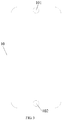
- a mobile terminal 100 may include a cover 10, a display screen 20, a circuit board 30, a battery 40, and a housing 50.
- the cover 10 may be mounted onto the display screen 20, in order to cover the display screen 20.
- the cover 10 may define a through hole 101 and a through hole 102.
- the through hole 101 and the through hole 102 may be defined at two opposite ends of the cover 10, respectively.
- the through hole 101 may be configured in such a way that a receiver of the mobile terminal 100 may transmit a sound signal to an outer side of the mobile terminal via the through hole.
- the through hole 101 may also be configured in such a way that a microphone of the mobile terminal 100 may collect an external sound signal via the through hole.
- the through hole 102 may be configured in such a way that a fingerprint module of the mobile terminal 100 may collect fingerprint information of a user via the through hole.
- the through hole 101 may be defined in the middle at a top end of the cover 10.
- the through hole 102 may be defined in the middle at a bottom end of the cover 10.
- the cover 10 may be a transparent glass cover.
- the cover 10 may be a glass cover made of a material such as sapphire or the like.
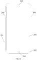
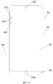
- the display screen 20 may be mounted on the housing 50 to form a display surface of the mobile terminal 100. As shown in FIG. 4 , the display screen 20 may include a display area 201 and a non-display area 202.
- the display area 201 may be configured to display information such as images, texts, or the like.
- the non-display area 202 may not display information.
- Functional components, such as the fingerprint module, a touch circuit, or the like, may be arranged at a bottom of the non-display area 202.
- a through hole 203 may be defined in the display area 201.
- the through hole 203 may be disposed correspondingly to the through hole 101 defined in the cover 10.
- the through hole 203 may be configured in such a way that a camera of the mobile terminal 100 may collect an external image signal via the through hole, a proximity sensor of the mobile terminal 100 may transmit and receive signals via the through hole, the receiver of the mobile terminal 100 may transmit the sound signal to the outer side of the mobile terminal via the through hole, and the microphone of the mobile terminal 100 may collect the external sound signal via the through hole.
- a through hole 204 may be defined in the non-display area 202.
- the through hole 204 may be disposed correspondingly to the through hole 102 defined in the cover 10.
- the through hole 204 may be configured in such a way that the fingerprint module of the mobile terminal 100 may collect the fingerprint information of the user via the through hole.
- the through hole 203 may be defined in the middle at a top end of the display area 201.
- the through hole 204 may be defined in the middle at a bottom end of the non-display area 202.
- the circuit board 30 may be disposed inside the housing 50.
- the circuit board 30 may be configured as a main board of the mobile terminal 100.
- Functional components such as the camera, the proximity sensor, the receiver, the microphone, or the like, may be integrated on the circuit board 30.
- the display screen 20 may be electrically connected to the circuit board 30.
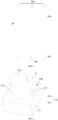
- the camera 31 may be integrated on the circuit board 30.
- the camera 31 may include a base 311 and a lens 312.
- the lens 312 may be mounted on the base 311.
- a contour of the base 311 may be in shape of a rectangle or in other shapes such as a circle or the like.
- a size of the contour of the base 311 may be greater than that of the lens 312, such that a step portion 310 may form on a mounting surface of the lens 312 on the base 311.
- a step surface of the step portion 310 may face towards the display screen 20 of the mobile terminal 100.
- a sensor assembly 32 may be arranged on the step portion 310.
- the sensor assembly 32 may include a signal transmitter 321 and a signal receiver 322.
- the signal transmitter 321 and the signal receiver 322 may form the proximity sensor.
- the signal transmitter 321 and the signal receiver 322 may be electrically connected to the circuit board 30.
- the signal transmitter 321 may be configured to transmit a signal.
- the signal is reflected by an external object to form a reflection signal
- the signal receiver 322 may be configured to receive the reflection signal.
- the mobile terminal 100 may determine a distance between the mobile terminal 100 and the external object based on an intensity of the reflection signal, thereby controlling a display state of the display screen 20.
- the signal may be an optical signal such as an infrared ray, a laser, or the like.
- the signal may also be the sound signal such as an ultrasonic wave signal or the like.
- the signal may also be other types of signals.
- the signal transmitter 321 and the signal receiver 322 may be disposed at two opposite sides of the lens 312 along a width direction of the mobile terminal 100.
- the signal transmitter 321 and the signal receiver 322 may also be disposed at two opposite sides of the lens 312 along a length direction of the mobile terminal 100.
- the step portion 310 forms on the camera 31, and the sensor assembly 32 is mounted on the step portion 310, it is unnecessary to define a separate hole in the mobile terminal 100 for the sensor assembly 32. Therefore, the sensor assembly 32 will not occupy the display area on the screen of the mobile terminal 100, that is, the screen ratio of the display area of the screen may be increased.
- the sensor assembly 32 may also include an ambient light sensor 323.
- the ambient light sensor 323 may be disposed around the lens 312 and arranged on the step portion 310.
- the ambient light sensor 323 may also be electrically coupled to circuit board 30 and configured to receive an ambient light signal.
- the mobile terminal 100 may adjust the brightness of the display screen 20 based on an intensity of the ambient light signal.
- the battery 40 may be disposed inside the housing 50.
- the battery 40 may be configured to provide power supply to the mobile terminal 100.
- the housing 50 may be configured to form an outer contour of the mobile terminal 100.
- the housing 50 may be made of plastic or metal.
- the housing 50 may integrally form as one component.
- FIG. 7 is a sectional view of the mobile terminal of FIG. 1 taken along the P-P direction.
- the housing 50 may form the outer contour of the mobile terminal 100.
- the circuit board 30 may be disposed inside the housing 50.
- the camera 31, the receiver 601, and the microphone 701 may be integrated on the circuit board 30.
- the receiver 601 and the microphone 701 may be disposed around the camera 31. When viewed from the outer side of the mobile terminal 100, the receiver 601 and the microphone 701 may be hidden and invisible.
- the step portion 310 may form on the camera 31.
- the signal transmitter 321 and the signal receiver 322 may be disposed on the step portion 310.
- the signal transmitter 321 and the signal receiver 322 may be disposed at two opposite sides of the lens of the camera 31 along the width direction of the mobile terminal 100.
- the display screen 20 may be disposed on the housing 50, and the through hole 203 may be defined in the display screen 20.
- the cover 10 may be disposed on the display screen 20 to cover the display screen 20.
- the cover 10 may define the through hole 101.
- the through hole 101 may be disposed correspondingly to the through hole 203 defined in the display screen 20.
- the camera 31 may be configured to collect the external image signal via the through hole 203 and the through hole 101.
- the signal transmitter 321 may be configured to transmit the signal to the outer side via the through hole 203 and the through hole 101.
- the signal receiver 322 may be configured to receive the reflection signal reflected by the external object via the through hole 203 and the through hole 101.
- the receiver 601 may be configured to transmit the sound signal to the outer side via the through hole 203 and the through hole 101.
- the microphone 701 may be configured to collect the external sound signal via the through hole 203 and the through hole 101.
- FIG. 8 is another schematic structural view of the mobile terminal 100 according to some embodiments of the present disclosure.
- the display screen 20 may include a display area 201 and a non-display area 202.
- the display area 201 may be configured to display information such as images, texts, or the like.
- the non-display area 202 may not display information.
- Functional components such as a fingerprint module, a touch circuit, or the like, may be arranged at a bottom of the non-display area 202
- a through hole 203 may be defined in the display area 201.
- the through hole 203 may be configured in such a way that a camera of the mobile terminal 100 may collect an external image signal via the through hole, and that a proximity sensor of the mobile terminal 100 may transmit and receive signals via the through hole.
- a through hole 204 may be defined in the non-display area 202.
- the through hole 204 may be configured in such a way that the fingerprint module of the mobile terminal 100 may collect the fingerprint information of the user via the through hole.
- a slot 801 and a slot 802 may be defined by two opposite sides of the display screen 20 and corresponding inner sides of the housing 50.
- the slot 801 and the slot 802 may be defined at an upper portion of the mobile terminal 100. Additional slots may be defined in the cover of the mobile terminal 100 and corresponding to the slot 801 and the slot 802.
- the mobile terminal 100 may include two receivers (the receiver 601 and the receiver 602).
- the receiver 601 and the receiver 602 may be disposed below the display screen 20. When viewed from the outer side of the mobile terminal 100, the receiver 601 and the receiver 602 may be hidden and invisible.
- the receiver 601 may be disposed at a position adjacent to the slot 801 and configured to transmit the sound signal to the outer side via the slot 801.
- the receiver 602 may be disposed at a position adjacent to the slot 802 and configured to transmit the sound signal to the outer side via the slot 802.
- the mobile terminal 100 may also include the microphone 701.
- the microphone 701 may be disposed below the display screen 20. When viewed from the outer side of the mobile terminal 100, the microphone 701 may be hidden and invisible.
- the microphone 701 may be disposed at a position adjacent to the slot 801 and configured to collect the external sound signal via the slot 801.
- the microphone 701 may also be disposed at a position adjacent to the slot 802. In this case, the microphone 701 may be configured to collect the external sound signal via the slot 802.
- the number of the microphones may also be two.
- the two microphones may be respectively disposed adjacent to the slot 801 and the slot 802 and configured to collect the external sound signals via the slot 801 and the slot 802, respectively.
- FIG. 9 is a partially enlarged view of a region A of the mobile terminal shown in FIG. 8
- FIG. 10 is a partially enlarged view of a region B of the mobile terminal shown in FIG. 8 .
- the slot 801 and the slot 802 may be in shape of such as an elongated rectangle or a rounded rectangle.
- Each of the slot 801 and the slot 802 may have a width d ranged between 0.4 mm and 0.5 mm.
- the slot 801 and the slot 802 having the width ranged between 0.4 mm and 0.5 mm are difficult for the user to perceive.
- the slot 801 and the slot 802 having the width ranged between 0.4 mm and 0.5 mm may hardly occupy the width of the screen, such that the screen ratio of the display area to the screen may be increased.
- the slot 801 and the slot 802 may be defined by a notch 205 and a notch 206 defined at two opposite sides of the display screen 20.
- the notch 205 and the notch 206 may be defined at two opposite sides of the display screen.
- the slot 801 and the slot 802 may be defined by two opposite sides of the display screen 20 and the corresponding inner sides of the housing 50.
- the slot 801 and the slot 802 may also be defined by notches defined at two inner sides of the housing 50.
- a notch 103 may be defined in the cover 10 at a position corresponding to the notch 205 defined in the display screen 20, and a notch 104 may be defined in the cover 10 at a position corresponding to the notch 206 defined in the display screen 20.
- the notch 103 may be disposed correspondingly to the notch 205, such that a through hole defined from an inner side to the outer side may be defined at one side of the mobile terminal 100.
- the notch 104 disposed correspondingly to the notch 206, such that a through hole defined from the inner side to the outer side may be defined at the other side of the mobile terminal 100.
- the through hole may facilitate the transmission of the sound signal, such that the sound signal generated by the receiver of the mobile terminal 100 may be transmitted to the outer side of the mobile terminal, while the microphone of the mobile terminal 100 may collect the external sound signal.
- one receiver and one microphone are provided in the mobile terminal 100.
- one slot is defined at the side of the mobile terminal 100.
- the slot 801 may be defined by one side of the display screen 20 and one inner side of the housing 50.
- the receiver 601 and the microphone 701 may be both disposed below the display screen 20.
- the receiver 601 and the microphone 701 may be both disposed close the slot 801.
- the receiver 601 may be configured to transmit the sound signal to the outer side via the slot 801, and the microphone 701 may be configured to collect the external sound signal via the slot 801.
Abstract
Description
- This application claims priority to Chinese Patent Application No.
201710132220.3 - The present disclosure relates to the field of communication technologies, and in particular, to a mobile terminal.
- In a conventional mobile terminal (for example, a smart phone), a receiver is installed inside the mobile terminal, and a hole is defined at a top corresponding to the receiver. The receiver transmits sound waves to an outer side of the mobile terminal via the hole, such that the mobile terminal is capable of transmitting a sound signal to a user.
- However, in this design, the hole defined on a screen is large. Defining the hole on the screen needs to occupy a wider width of the screen of the mobile terminal, thereby resulting in a lower screen ratio of a display area to the screen.
- The embodiments of the present disclosure provided a mobile terminal, which may increase the screen ratio of the display area to the screen of the mobile terminal.
- The embodiments of the present disclosure provided a mobile terminal. The mobile terminal includes a housing, a display screen, a camera, and a sensor assembly.
- The display screen is mounted on the housing and defines a first through hole. The camera is mounted in the first through hole.
- A step portion forms on the camera, and the step portion comprises a step surface facing towards the display screen. The sensor assembly is mounted on the step portion.
- The embodiments of the present disclosure provided a mobile terminal, which may increase the screen ratio of the display area to the screen of the mobile terminal.
- In order to describe the technical solutions in the embodiments of the present disclosure more clearly, the following briefly introduces the accompanying drawings required for describing the embodiments. Apparently, the accompanying drawings in the following description are merely some embodiments of the present disclosure, those skilled in the art may acquire other drawings based on these drawings without creative efforts.
-
FIG. 1 is a first schematic view of a mobile terminal according to some embodiments of the present disclosure. -
FIG. 2 is an exploded view of the mobile terminal according to some embodiments of the present disclosure. -
FIG. 3 is a first schematic view of a cover according to some embodiments of the present disclosure. -
FIG. 4 is a first schematic view of a display screen according to some embodiments of the present disclosure. -
FIG. 5 is a first schematic view of a camera according to some embodiments of the present disclosure. -
FIG. 6 is a second schematic view of a camera according to some embodiments of the present disclosure. -
FIG. 7 is a sectional view of the mobile terminal shown inFIG. 1 and taken along P-P direction. -
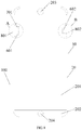
FIG. 8 is a second schematic view of a mobile terminal according to some embodiments of the present disclosure. -
FIG. 9 is a partially enlarged view of a region A of the mobile terminal shown inFIG. 8 . -
FIG. 10 is a partially enlarged view of a region B of the mobile terminal shown inFIG. 8 . -
FIG. 11 is a second schematic view of a display screen according to some embodiments of the present disclosure. -
FIG. 12 is a second schematic view of a cover according to some embodiments of the present disclosure. -
FIG. 13 is a third schematic view of a mobile terminal according to some embodiments of the present disclosure. - The technical solutions in the embodiments of the present disclosure will be clearly and completely described in detail below with reference to the accompanying drawings in the embodiments of the present disclosure. Apparently, the embodiments described herein are only some exemplary embodiments, not all the embodiments. Based on the embodiments described in the present disclosure, those skilled in the art may acquire all other embodiments without any creative efforts. All these shall be covered within the protection scope of the present disclosure.
- In the description of the embodiments of the present disclosure, it should be understood that, the orientation or positional relationships indicated by the terms "center", "longitudinal", "transverse", "length", "width", "thickness", "upper", "lower", "front", "rear", "left", "right", "vertical", "horizontal", "top", "bottom", "inner", "outer", "clockwise", "counterclockwise", or the like, are based on the orientation or positional relationship shown in the drawings, and are merely for convenience of description and for simplifying description, rather than implying or indicating that the device or the component must have a particular orientation or constructed and operated in a particular orientation, and thus these terms cannot to be construed as limiting the present disclosure. In addition, terms such as "first", "second", or the like, are used herein for purposes of description, and are not intended to indicate or imply relative importance or to imply the number of indicated technical features. Thus, the feature defined with "first", "second", or the like may include one or more of such a feature. In the description of the present disclosure, it should be noted that, "a plurality of' means two or more, unless specified otherwise.
- In the present disclosure, it should be noted that, unless specified or limited, otherwise, terms "mounted", "connected", "connected", or the like may be used in a broad sense, and may include, for example, fixed connections, detachable connections, or integral connections; may also be mechanical, electrical connections, or communications; may also be direct connections or indirect connections via intervening structures; may also be inner communications of two elements, as can be understood by one skilled in the art depending on specific contexts.
- In the present disclosure, a first feature being located "above" or "below" a second feature may include an embodiment in which the first feature is in direct contact with the second feature and an embodiment in which another feature is formed between the first and the second features such that the first feature is not in direct contact with the second feature. Moreover, the first feature being disposed "on", "above", and "upon" the second feature may indicate that the first feature is disposed directly above and obliquely above the second feature, or merely indicate that the first feature is at a higher level than the second feature. The first feature being disposed "below", "under" and "beneath" the second feature may indicate that the first feature is disposed directly below and obliquely below the second feature, or merely indicate that the first feature is at a lower level than the second feature.
- The following disclosure provides many different embodiments or examples for implementing different structures of the present disclosure. In order to simplify the present disclosure, components and arrangements of specific examples are described below. Of course, these are merely examples, and are not intended to limit the present disclosure. In addition, reference numerals and/or reference letters are repeated in different examples of the present disclosure. The repetition is for the purpose of simplicity and clarity, and do not indicate the relationship between various embodiments and/or arrangements discussed herein. Moreover, examples of various specific processes and materials are provided in the present disclosure. However, those skilled in the art may recognize applications of other processes and/or usages of other materials.
- The embodiments of the present disclosure provided a mobile terminal. The mobile terminal includes a housing, a display screen, a camera, and a sensor assembly.
- The display screen is mounted on the housing and defines a first through hole. The camera is mounted in the first through hole.
- A step portion forms on the camera, and the step portion comprises a step surface facing towards the display screen. The sensor assembly is mounted on the step portion.
- In some embodiments, the camera comprises a lens, and the sensor assembly comprises a signal transmitter and a signal receiver; the signal transmitter and the signal receiver are disposed at two opposite sides of the lens along a width direction of the mobile terminal.
- In some embodiments, the camera comprises a lens, and the sensor assembly comprises a signal transmitter and a signal receiver; the signal transmitter and the signal receiver are disposed at two opposite sides of the lens along a length direction of the mobile terminal.
- In some embodiments, the signal transmitter is configured to transmit a signal; the signal is reflected by an external object to form a reflection signal, and the signal receiver is configured to receive the reflection signal; the signal comprises at least one of an infrared ray, a laser, and an ultrasonic wave.
- In some embodiments, the mobile terminal is configured to control a display state of the display screen based on an intensity of the reflection signal.
- In some embodiments, the sensor assembly comprises an ambient light sensor configured to receive an ambient light signal via the first through hole.
- In some embodiments, the mobile terminal adjusts a brightness of the display screen based on an intensity of the ambient light signal.
- In some embodiments, the camera comprises a base and a lens mounted on the base; a size of a contour of the base is greater than that of the lens. The step portion forms on a mounting surface of the lens and the base.
- In some embodiments, the base is in shape of a rectangle or a circle.
- In some embodiments, the mobile terminal may include further a cover and a receiver.
- The cover covers the display screen and defines a second through hole at a position corresponding to the first through hole.
- The receiver may be mounted inside the housing and configured to transmit a sound signal to an outer side of the mobile terminal via the first through hole and the second through hole.
- In some embodiments, the mobile terminal may further include a microphone. The microphone is mounted inside the housing and configured to collect an external sound signal via the first through hole and the second through hole.
- In some embodiments, the mobile terminal may further include a cover and a receiver.
- A slot is defined by at least one side of the display screen and the housing.
- The cover covers the display screen and a notch is defined in the cover at a position corresponding to the slot.
- The receiver is mounted inside the housing and configured to transmit a sound signal to an outer side of the mobile terminal via the slot and the notch.
- In some embodiments, the mobile terminal may further include a microphone. The microphone is mounted inside the housing and configured to collect an external sound signal via the slot and the notch.
- In some embodiments, the slot is in shape of a rectangle or a rounded rectangle.
- In some embodiments, the slot has a width ranged between 0.4 mm and 0.5 mm.
- In some embodiments, the mobile terminal may further include a cover and two receivers.
- Slots are defined by two opposite sides of the display screen and corresponding sides of the housing.
- The cover covers the display screen, and notches are defined by two opposite sides of cover at positions corresponding to the slots.
- The receivers are mounted inside the housing, and each of the receivers is configured to transmit a sound signal to an outer side of the mobile terminal via one of the slots and the corresponding notch.
- In some embodiments, each of the slots is in shape of a rectangle or a rounded rectangle.
- In some embodiments, each of the slots has a width ranged between 0.4 mm and 0.5 mm.
- As shown in
FIGS. 1 and2 , amobile terminal 100 may include acover 10, adisplay screen 20, acircuit board 30, abattery 40, and ahousing 50. - The
cover 10 may be mounted onto thedisplay screen 20, in order to cover thedisplay screen 20. As shown inFIG. 3 , thecover 10 may define a throughhole 101 and a throughhole 102. The throughhole 101 and the throughhole 102 may be defined at two opposite ends of thecover 10, respectively. The throughhole 101 may be configured in such a way that a receiver of themobile terminal 100 may transmit a sound signal to an outer side of the mobile terminal via the through hole. At the same time, the throughhole 101 may also be configured in such a way that a microphone of themobile terminal 100 may collect an external sound signal via the through hole. The throughhole 102 may be configured in such a way that a fingerprint module of themobile terminal 100 may collect fingerprint information of a user via the through hole. - In some embodiments, the through
hole 101 may be defined in the middle at a top end of thecover 10. The throughhole 102 may be defined in the middle at a bottom end of thecover 10. - The
cover 10 may be a transparent glass cover. In some embodiments, thecover 10 may be a glass cover made of a material such as sapphire or the like. - The
display screen 20 may be mounted on thehousing 50 to form a display surface of themobile terminal 100. As shown inFIG. 4 , thedisplay screen 20 may include adisplay area 201 and anon-display area 202. Thedisplay area 201 may be configured to display information such as images, texts, or the like. Thenon-display area 202 may not display information. Functional components, such as the fingerprint module, a touch circuit, or the like, may be arranged at a bottom of thenon-display area 202. - A through
hole 203 may be defined in thedisplay area 201. The throughhole 203 may be disposed correspondingly to the throughhole 101 defined in thecover 10. The throughhole 203 may be configured in such a way that a camera of themobile terminal 100 may collect an external image signal via the through hole, a proximity sensor of themobile terminal 100 may transmit and receive signals via the through hole, the receiver of themobile terminal 100 may transmit the sound signal to the outer side of the mobile terminal via the through hole, and the microphone of themobile terminal 100 may collect the external sound signal via the through hole. - A through
hole 204 may be defined in thenon-display area 202. The throughhole 204 may be disposed correspondingly to the throughhole 102 defined in thecover 10. The throughhole 204 may be configured in such a way that the fingerprint module of themobile terminal 100 may collect the fingerprint information of the user via the through hole. - In some embodiments, the through
hole 203 may be defined in the middle at a top end of thedisplay area 201. The throughhole 204 may be defined in the middle at a bottom end of thenon-display area 202. - The
circuit board 30 may be disposed inside thehousing 50. Thecircuit board 30 may be configured as a main board of themobile terminal 100. Functional components, such as the camera, the proximity sensor, the receiver, the microphone, or the like, may be integrated on thecircuit board 30. Meanwhile, thedisplay screen 20 may be electrically connected to thecircuit board 30. - As shown in
FIG. 5 , thecamera 31 may be integrated on thecircuit board 30. Thecamera 31 may include abase 311 and alens 312. Thelens 312 may be mounted on thebase 311. A contour of the base 311 may be in shape of a rectangle or in other shapes such as a circle or the like. A size of the contour of the base 311 may be greater than that of thelens 312, such that astep portion 310 may form on a mounting surface of thelens 312 on thebase 311. A step surface of thestep portion 310 may face towards thedisplay screen 20 of themobile terminal 100. - A
sensor assembly 32 may be arranged on thestep portion 310. Thesensor assembly 32 may include asignal transmitter 321 and asignal receiver 322. Thesignal transmitter 321 and thesignal receiver 322 may form the proximity sensor. Thesignal transmitter 321 and thesignal receiver 322 may be electrically connected to thecircuit board 30. - The
signal transmitter 321 may be configured to transmit a signal. The signal is reflected by an external object to form a reflection signal, and thesignal receiver 322 may be configured to receive the reflection signal. Themobile terminal 100 may determine a distance between themobile terminal 100 and the external object based on an intensity of the reflection signal, thereby controlling a display state of thedisplay screen 20. - The signal may be an optical signal such as an infrared ray, a laser, or the like. The signal may also be the sound signal such as an ultrasonic wave signal or the like. The signal may also be other types of signals.
- The
signal transmitter 321 and thesignal receiver 322 may be disposed at two opposite sides of thelens 312 along a width direction of themobile terminal 100. Thesignal transmitter 321 and thesignal receiver 322 may also be disposed at two opposite sides of thelens 312 along a length direction of themobile terminal 100. - Since the
step portion 310 forms on thecamera 31, and thesensor assembly 32 is mounted on thestep portion 310, it is unnecessary to define a separate hole in themobile terminal 100 for thesensor assembly 32. Therefore, thesensor assembly 32 will not occupy the display area on the screen of themobile terminal 100, that is, the screen ratio of the display area of the screen may be increased. - As shown in
FIG. 6 , thesensor assembly 32 may also include an ambientlight sensor 323. The ambientlight sensor 323 may be disposed around thelens 312 and arranged on thestep portion 310. The ambientlight sensor 323 may also be electrically coupled tocircuit board 30 and configured to receive an ambient light signal. Themobile terminal 100 may adjust the brightness of thedisplay screen 20 based on an intensity of the ambient light signal. - The
battery 40 may be disposed inside thehousing 50. Thebattery 40 may be configured to provide power supply to themobile terminal 100. - The
housing 50 may be configured to form an outer contour of themobile terminal 100. Thehousing 50 may be made of plastic or metal. Thehousing 50 may integrally form as one component. - As shown in
FIG. 7, FIG. 7 is a sectional view of the mobile terminal ofFIG. 1 taken along the P-P direction. - The
housing 50 may form the outer contour of themobile terminal 100. - The
circuit board 30 may be disposed inside thehousing 50. Thecamera 31, thereceiver 601, and themicrophone 701 may be integrated on thecircuit board 30. Thereceiver 601 and themicrophone 701 may be disposed around thecamera 31. When viewed from the outer side of themobile terminal 100, thereceiver 601 and themicrophone 701 may be hidden and invisible. Thestep portion 310 may form on thecamera 31. Thesignal transmitter 321 and thesignal receiver 322 may be disposed on thestep portion 310. Thesignal transmitter 321 and thesignal receiver 322 may be disposed at two opposite sides of the lens of thecamera 31 along the width direction of themobile terminal 100. - The
display screen 20 may be disposed on thehousing 50, and the throughhole 203 may be defined in thedisplay screen 20. - The
cover 10 may be disposed on thedisplay screen 20 to cover thedisplay screen 20. Thecover 10 may define the throughhole 101. The throughhole 101 may be disposed correspondingly to the throughhole 203 defined in thedisplay screen 20. - The
camera 31 may be configured to collect the external image signal via the throughhole 203 and the throughhole 101. Thesignal transmitter 321 may be configured to transmit the signal to the outer side via the throughhole 203 and the throughhole 101. Thesignal receiver 322 may be configured to receive the reflection signal reflected by the external object via the throughhole 203 and the throughhole 101. Thereceiver 601 may be configured to transmit the sound signal to the outer side via the throughhole 203 and the throughhole 101. Themicrophone 701 may be configured to collect the external sound signal via the throughhole 203 and the throughhole 101. - As shown in
FIG. 8, FIG. 8 is another schematic structural view of themobile terminal 100 according to some embodiments of the present disclosure. - In some embodiments, the
display screen 20 may include adisplay area 201 and anon-display area 202. Thedisplay area 201 may be configured to display information such as images, texts, or the like. Thenon-display area 202 may not display information. Functional components, such as a fingerprint module, a touch circuit, or the like, may be arranged at a bottom of thenon-display area 202 - A through
hole 203 may be defined in thedisplay area 201. The throughhole 203 may be configured in such a way that a camera of themobile terminal 100 may collect an external image signal via the through hole, and that a proximity sensor of themobile terminal 100 may transmit and receive signals via the through hole. - A through
hole 204 may be defined in thenon-display area 202. The throughhole 204 may be configured in such a way that the fingerprint module of themobile terminal 100 may collect the fingerprint information of the user via the through hole. - A
slot 801 and aslot 802 may be defined by two opposite sides of thedisplay screen 20 and corresponding inner sides of thehousing 50. Theslot 801 and theslot 802 may be defined at an upper portion of themobile terminal 100. Additional slots may be defined in the cover of themobile terminal 100 and corresponding to theslot 801 and theslot 802. Themobile terminal 100 may include two receivers (thereceiver 601 and the receiver 602). Thereceiver 601 and thereceiver 602 may be disposed below thedisplay screen 20. When viewed from the outer side of themobile terminal 100, thereceiver 601 and thereceiver 602 may be hidden and invisible. - In some embodiments, the
receiver 601 may be disposed at a position adjacent to theslot 801 and configured to transmit the sound signal to the outer side via theslot 801. Thereceiver 602 may be disposed at a position adjacent to theslot 802 and configured to transmit the sound signal to the outer side via theslot 802. - The
mobile terminal 100 may also include themicrophone 701. Themicrophone 701 may be disposed below thedisplay screen 20. When viewed from the outer side of themobile terminal 100, themicrophone 701 may be hidden and invisible. - In some embodiments, the
microphone 701 may be disposed at a position adjacent to theslot 801 and configured to collect the external sound signal via theslot 801. - In some embodiments, the
microphone 701 may also be disposed at a position adjacent to theslot 802. In this case, themicrophone 701 may be configured to collect the external sound signal via theslot 802. - In some embodiments, the number of the microphones may also be two. The two microphones may be respectively disposed adjacent to the
slot 801 and theslot 802 and configured to collect the external sound signals via theslot 801 and theslot 802, respectively. - As shown in
FIG. 9 and FIG. 10, FIG. 9 is a partially enlarged view of a region A of the mobile terminal shown inFIG. 8 , andFIG. 10 is a partially enlarged view of a region B of the mobile terminal shown inFIG. 8 . - In some embodiments, the
slot 801 and theslot 802 may be in shape of such as an elongated rectangle or a rounded rectangle. Each of theslot 801 and theslot 802 may have a width d ranged between 0.4 mm and 0.5 mm. Theslot 801 and theslot 802 having the width ranged between 0.4 mm and 0.5 mm are difficult for the user to perceive. On the other hand, theslot 801 and theslot 802 having the width ranged between 0.4 mm and 0.5 mm may hardly occupy the width of the screen, such that the screen ratio of the display area to the screen may be increased. - As shown in
FIG. 11 , theslot 801 and theslot 802 may be defined by anotch 205 and anotch 206 defined at two opposite sides of thedisplay screen 20. Thenotch 205 and thenotch 206 may be defined at two opposite sides of the display screen. After the assembly of themobile terminal 100 is finished, theslot 801 and theslot 802 may be defined by two opposite sides of thedisplay screen 20 and the corresponding inner sides of thehousing 50. - In some embodiments, the
slot 801 and theslot 802 may also be defined by notches defined at two inner sides of thehousing 50. - As shown in
FIG. 12 , anotch 103 may be defined in thecover 10 at a position corresponding to thenotch 205 defined in thedisplay screen 20, and anotch 104 may be defined in thecover 10 at a position corresponding to thenotch 206 defined in thedisplay screen 20. - In some embodiments, the
notch 103 may be disposed correspondingly to thenotch 205, such that a through hole defined from an inner side to the outer side may be defined at one side of themobile terminal 100. Thenotch 104 disposed correspondingly to thenotch 206, such that a through hole defined from the inner side to the outer side may be defined at the other side of themobile terminal 100. The through hole may facilitate the transmission of the sound signal, such that the sound signal generated by the receiver of themobile terminal 100 may be transmitted to the outer side of the mobile terminal, while the microphone of themobile terminal 100 may collect the external sound signal. - In some embodiments, as shown in
FIG. 13 , one receiver and one microphone are provided in themobile terminal 100. In this case, one slot is defined at the side of themobile terminal 100. - In some embodiments, the
slot 801 may be defined by one side of thedisplay screen 20 and one inner side of thehousing 50. Thereceiver 601 and themicrophone 701 may be both disposed below thedisplay screen 20. Thereceiver 601 and themicrophone 701 may be both disposed close theslot 801. Thereceiver 601 may be configured to transmit the sound signal to the outer side via theslot 801, and themicrophone 701 may be configured to collect the external sound signal via theslot 801. - The mobile terminal provided by the embodiments of the present disclosure is described in detail. The specific examples are used herein to explain principles and embodiments of the present disclosure. The description of the above embodiments is only for helping to understand the present disclosure. Meanwhile, those skilled in the art may change the specific embodiments and the application according to the idea of the present disclosure. In conclusion, the content of the specification should not be construed as a limitation to the present disclosure.
Claims (18)
- A mobile terminal, comprising:a housing,a display screen, mounted on the housing and defining a first through hole;a camera, mounted in the first through hole, wherein a step portion forms on the camera, and the step portion comprises a step surface facing towards the display screen; anda sensor assembly, mounted on the step surface of the step portion.
- The mobile terminal of claim 1, wherein the camera comprises a lens, and the sensor assembly comprises a signal transmitter and a signal receiver; the signal transmitter and the signal receiver are disposed at two opposite sides of the lens along a width direction of the mobile terminal.
- The mobile terminal of claim 1, wherein the camera comprises a lens, and the sensor assembly comprises a signal transmitter and a signal receiver; the signal transmitter and the signal receiver are disposed at two opposite sides of the lens along a length direction of the mobile terminal.
- The mobile terminal of claims 2 or 3, wherein the signal transmitter is configured to transmit a signal; the signal is reflected by an external object to form a reflection signal, and the signal receiver is configured to receive the reflection signal; the signal comprises at least one of an infrared ray, a laser, and an ultrasonic wave.
- The mobile terminal of claim 4, wherein the mobile terminal is configured to control a display state of the display screen based on an intensity of the reflection signal.
- The mobile terminal of claim 1, wherein the sensor assembly comprises an ambient light sensor configured to receive an ambient light signal via the first through hole.
- The mobile terminal of claim 6, wherein the mobile terminal adjusts a brightness of the display screen based on an intensity of the ambient light signal.
- The mobile terminal of claim 1, wherein the camera comprises a base and a lens mounted on the base; a size of a contour of the base is greater than that of the lens; the step portion forms on a mounting surface of the lens and the base.
- The mobile terminal of claim 8, wherein the base is in shape of a rectangle or a circle.
- The mobile terminal of claim 1, further comprising:a cover, covering the display screen and defining a second through hole at a position corresponding to the first through hole; anda receiver, mounted inside the housing and configured to transmit a sound signal to an outer side of the mobile terminal via the first through hole and the second through hole.
- The mobile terminal of claim 10, further comprising a microphone; wherein the microphone is mounted inside the housing and configured to collect an external sound signal via the first through hole and the second through hole.
- The mobile terminal of claim 1, further comprising a cover and a receiver;
wherein a slot is defined by at least one side of the display screen and the housing;
the cover covers the display screen, and a notch is defined in the cover at a position corresponding to the slot;
the receiver is mounted inside the housing and configured to transmit a sound signal to an outer side of the mobile terminal via the slot and the notch. - The mobile terminal of claim 12, further comprising a microphone; wherein the microphone is mounted inside the housing and configured to collect an external sound signal via the slot and the notch.
- The mobile terminal of claim 12, wherein the slot is in shape of a rectangle or a rounded rectangle.
- The mobile terminal of claim 12, wherein the slot has a width ranged between 0.4 mm and 0.5 mm.
- The mobile terminal of claim 1, further comprising a cover and two receivers; wherein slots are defined by two opposite sides of the display screen and corresponding sides of the housing;
the cover covers the display screen, and notches are defined by two opposite sides of cover at positions corresponding to the slots;
the receivers are mounted inside the housing, and each of the receivers is configured to transmit a sound signal to an outer side of the mobile terminal via one of the slots and the corresponding notch. - The mobile terminal of claim 16, wherein each of the slots is in shape of a rectangle or a rounded rectangle.
- The mobile terminal of claim 16, wherein each of the slots has a width ranged between 0.4 mm and 0.5 mm.
Applications Claiming Priority (2)
| Application Number | Priority Date | Filing Date | Title |
|---|---|---|---|
| CN201710132220.3A CN106657485B (en) | 2017-03-07 | 2017-03-07 | Mobile terminal |
| PCT/CN2018/074495 WO2018161736A1 (en) | 2017-03-07 | 2018-01-29 | Mobile terminal |
Publications (3)
| Publication Number | Publication Date |
|---|---|
| EP3582472A1 true EP3582472A1 (en) | 2019-12-18 |
| EP3582472A4 EP3582472A4 (en) | 2019-12-18 |
| EP3582472B1 EP3582472B1 (en) | 2021-03-24 |
Family
ID=58848003
Family Applications (1)
| Application Number | Title | Priority Date | Filing Date |
|---|---|---|---|
| EP18763659.2A Active EP3582472B1 (en) | 2017-03-07 | 2018-01-29 | Mobile terminal |
Country Status (4)
| Country | Link |
|---|---|
| US (1) | US11025759B2 (en) |
| EP (1) | EP3582472B1 (en) |
| CN (1) | CN106657485B (en) |
| WO (1) | WO2018161736A1 (en) |
Families Citing this family (26)
| Publication number | Priority date | Publication date | Assignee | Title |
|---|---|---|---|---|
| CN106843389B (en) | 2017-01-09 | 2022-08-05 | Oppo广东移动通信有限公司 | Electronic device |
| CN106657485B (en) | 2017-03-07 | 2020-05-12 | Oppo广东移动通信有限公司 | Mobile terminal |
| CN111447309B (en) | 2017-03-07 | 2022-04-29 | Oppo广东移动通信有限公司 | Mobile terminal |
| CN107277196A (en) * | 2017-05-22 | 2017-10-20 | 广东欧珀移动通信有限公司 | Display module and its mobile terminal of application |
| CN107172240B (en) | 2017-06-27 | 2019-01-22 | 维沃移动通信有限公司 | A kind of cam device and mobile terminal |
| CN110663016B (en) * | 2017-06-30 | 2024-01-16 | 华为技术有限公司 | Method for displaying graphical user interface and mobile terminal |
| CN107277201B (en) * | 2017-07-31 | 2019-03-01 | 维沃移动通信有限公司 | A kind of fixing means and mobile terminal of camera |
| CN107395809B (en) * | 2017-08-15 | 2019-08-20 | 维沃移动通信有限公司 | A kind of light transmitting device and mobile terminal |
| WO2019062997A1 (en) * | 2017-09-30 | 2019-04-04 | 华为技术有限公司 | Terminal device and sound-emitting device |
| CN107967025B (en) * | 2017-11-22 | 2020-01-31 | Oppo广东移动通信有限公司 | Display screen assembly and electronic equipment |
| CN109936646A (en) * | 2017-12-15 | 2019-06-25 | 广东欧珀移动通信有限公司 | Electronic equipment |
| CN111953824B (en) * | 2017-12-26 | 2021-07-02 | Oppo广东移动通信有限公司 | Electronic device |
| CN110120990A (en) * | 2018-02-05 | 2019-08-13 | 广东欧珀移动通信有限公司 | Terminal display screen component and mobile terminal |
| CN110120991A (en) * | 2018-02-05 | 2019-08-13 | 广东欧珀移动通信有限公司 | Terminal display screen component and mobile terminal |
| CN108429830B (en) * | 2018-02-28 | 2020-12-08 | Oppo广东移动通信有限公司 | Electronic component and electronic equipment |
| CN108418915A (en) * | 2018-02-28 | 2018-08-17 | 广东欧珀移动通信有限公司 | Electronic building brick and electronic equipment |
| CN108418920B (en) * | 2018-03-06 | 2021-01-26 | 京东方科技集团股份有限公司 | Intelligent terminal and control method thereof |
| CN110312002A (en) * | 2018-03-20 | 2019-10-08 | 北京小米移动软件有限公司 | Terminal |
| CN108391038B (en) | 2018-04-24 | 2019-06-04 | Oppo广东移动通信有限公司 | Electronic device and its CCD camera assembly |
| CN110445909A (en) * | 2018-05-04 | 2019-11-12 | Oppo广东移动通信有限公司 | Mobile terminal |
| CN111433685B (en) * | 2018-07-12 | 2021-08-31 | Oppo广东移动通信有限公司 | Watch module, watch, electronic equipment, electronic device and mobile terminal |
| CN110798549B (en) * | 2018-08-01 | 2021-04-27 | Oppo广东移动通信有限公司 | Electronic device |
| CN111405098B (en) * | 2020-03-27 | 2022-03-18 | 维沃移动通信有限公司 | Electronic device |
| JP2021159415A (en) * | 2020-03-31 | 2021-10-11 | 株式会社ソニー・インタラクティブエンタテインメント | Input device |
| JP7387167B2 (en) * | 2020-05-01 | 2023-11-28 | tonari株式会社 | Virtual space connection device, system |
| CN113163041B (en) * | 2021-05-21 | 2023-08-15 | 维沃移动通信有限公司 | Electronic equipment |
Family Cites Families (53)
| Publication number | Priority date | Publication date | Assignee | Title |
|---|---|---|---|---|
| JPH08171477A (en) * | 1994-12-20 | 1996-07-02 | Matsushita Electric Ind Co Ltd | Portable information system equipment |
| US7388619B2 (en) | 2003-12-11 | 2008-06-17 | Sony Ericsson Mobile Communications Ab | Mobile device with a combination camera and loudspeaker |
| JP4411059B2 (en) | 2003-12-12 | 2010-02-10 | キヤノン株式会社 | Display device with camera, communication device, and communication system |
| JP4585409B2 (en) * | 2005-08-24 | 2010-11-24 | 株式会社東芝 | Small camera module |
| KR20070104010A (en) | 2006-04-21 | 2007-10-25 | 엘지이노텍 주식회사 | Camera module and mobile station having the same |
| WO2008018007A2 (en) | 2006-08-08 | 2008-02-14 | Nxp B.V. | Combination device of speaker and camera optical system |
| TWI411910B (en) * | 2008-05-29 | 2013-10-11 | Htc Corp | Handheld device and its power saving method |
| KR20090125547A (en) * | 2008-06-02 | 2009-12-07 | (주)나노지피 | Auto-focusing camera device for communication machine |
| KR101636461B1 (en) * | 2009-03-20 | 2016-07-05 | 삼성전자주식회사 | A hole construction for inputing and outputing sound of acoustic appliance in portable terminal |
| US8456586B2 (en) * | 2009-06-11 | 2013-06-04 | Apple Inc. | Portable computer display structures |
| US8913738B2 (en) * | 2009-06-30 | 2014-12-16 | Nokia Corporation | Apparatus with wideband earpiece response |
| KR101711830B1 (en) * | 2010-06-03 | 2017-03-03 | 엘지전자 주식회사 | Mobile terminal |
| JP2012114747A (en) * | 2010-11-25 | 2012-06-14 | Kyocera Corp | Covering unit for opening and electronic apparatus including the covering unit |
| US8947627B2 (en) * | 2011-10-14 | 2015-02-03 | Apple Inc. | Electronic devices having displays with openings |
| JP5284499B2 (en) * | 2012-01-31 | 2013-09-11 | 株式会社東芝 | Electronics |
| JP2013239788A (en) | 2012-05-11 | 2013-11-28 | Sharp Corp | Portable terminal |
| US9894781B2 (en) * | 2012-06-06 | 2018-02-13 | Apple Inc. | Notched display layers |
| KR101397084B1 (en) * | 2012-07-02 | 2014-05-20 | 엘지전자 주식회사 | Mobile terminal |
| US8988480B2 (en) * | 2012-09-10 | 2015-03-24 | Apple Inc. | Use of an earpiece acoustic opening as a microphone port for beamforming applications |
| KR101992189B1 (en) * | 2012-09-19 | 2019-06-24 | 엘지전자 주식회사 | Mobile terminal and method for controlling thereof |
| CN103841222A (en) * | 2012-11-20 | 2014-06-04 | 安谷通信技术(深圳)有限公司 | Mobile phone with full-screen display function |
| JP2014183396A (en) | 2013-03-18 | 2014-09-29 | Sharp Corp | Image pickup device and electronic apparatus |
| US9165444B2 (en) * | 2013-07-26 | 2015-10-20 | SkyBell Technologies, Inc. | Light socket cameras |
| KR102168200B1 (en) | 2013-09-17 | 2020-10-20 | 삼성전자주식회사 | Electronic device without front case frame |
| KR102107114B1 (en) * | 2013-10-30 | 2020-05-06 | 엘지전자 주식회사 | Mobile terminal |
| CN104793695A (en) * | 2014-01-17 | 2015-07-22 | 宏碁股份有限公司 | Handheld electronic device |
| CN203666511U (en) * | 2014-01-23 | 2014-06-25 | 金陵科技学院 | Automobile side view camera device |
| CN204119279U (en) | 2014-06-18 | 2015-01-21 | 锤子科技(北京)有限公司 | A kind of mobile terminal |
| CN104539833A (en) | 2015-01-07 | 2015-04-22 | 京东方科技集团股份有限公司 | Electronic device |
| CN204334759U (en) * | 2015-01-24 | 2015-05-13 | 江苏金成光电科技有限公司 | A kind of band light sensation mobile phone camera |
| CN104601763A (en) * | 2015-02-25 | 2015-05-06 | 胡伟 | Cellphone |
| EP3308242B1 (en) * | 2015-06-10 | 2021-08-11 | Fairphone B.V. | Connector for an electronic device |
| CN104950419B (en) | 2015-07-06 | 2017-09-29 | 南昌欧菲光电技术有限公司 | Camera module |
| US9807211B2 (en) | 2015-07-19 | 2017-10-31 | Otter Products, Llc | Protective modular case for electronic device |
| KR102489948B1 (en) * | 2016-02-18 | 2023-01-19 | 삼성전자주식회사 | Electronic device and manufacturing method thereof |
| CN205610701U (en) * | 2016-04-07 | 2016-09-28 | 广东欧珀移动通信有限公司 | Mobile terminal with front camera and large LCD |
| CN205453887U (en) | 2016-04-09 | 2016-08-10 | 兰州交通大学 | Seizure camera that accuracy is high |
| CN105791651B (en) * | 2016-04-14 | 2019-11-12 | 唐小川 | Camera module and picture pick-up device with flash lamp |
| US10009448B2 (en) * | 2016-04-28 | 2018-06-26 | Lg Electronics Inc. | Mobile terminal |
| CN205647713U (en) * | 2016-05-04 | 2016-10-12 | 江阴新晟电子有限公司 | Take iris recognition function's two megapixel cell -phone camera modules |
| CN205726042U (en) * | 2016-06-02 | 2016-11-23 | 奉化波导软件有限公司 | Camera structure and there is the mobile terminal of this camera structure |
| CN105991807A (en) | 2016-06-16 | 2016-10-05 | 珠海市魅族科技有限公司 | Receiver equipment used for mobile terminal and mobile terminal |
| WO2018006427A1 (en) * | 2016-07-08 | 2018-01-11 | 华为技术有限公司 | Battery cover and electronic device |
| CN106331235A (en) * | 2016-09-12 | 2017-01-11 | 努比亚技术有限公司 | Mobile terminal main board, mobile terminal main board setting method, and mobile terminal |
| CN106371187A (en) * | 2016-10-28 | 2017-02-01 | 圆融健康科技(深圳)有限公司 | Camera lens cone, camera module and mobile phone |
| CN106453722A (en) | 2016-11-30 | 2017-02-22 | 努比亚技术有限公司 | Telephone receiver device and mobile terminal |
| CN106453726B (en) * | 2016-12-06 | 2022-10-21 | Oppo广东移动通信有限公司 | Sensor assembly and terminal |
| CN106453724A (en) * | 2016-12-06 | 2017-02-22 | 广东欧珀移动通信有限公司 | Panel, sensor assembly and mobile terminal |
| CN106453725B (en) * | 2016-12-06 | 2023-04-07 | Oppo广东移动通信有限公司 | Terminal device |
| KR20180098466A (en) * | 2017-02-25 | 2018-09-04 | 삼성전자주식회사 | Electronic device comprising display having rounded corners |
| CN111447309B (en) | 2017-03-07 | 2022-04-29 | Oppo广东移动通信有限公司 | Mobile terminal |
| CN106657485B (en) * | 2017-03-07 | 2020-05-12 | Oppo广东移动通信有限公司 | Mobile terminal |
| KR102503420B1 (en) * | 2018-01-02 | 2023-02-24 | 삼성전자주식회사 | Camera module having elasticity and mobile device with the same |
-
2017
- 2017-03-07 CN CN201710132220.3A patent/CN106657485B/en active Active
-
2018
- 2018-01-29 WO PCT/CN2018/074495 patent/WO2018161736A1/en unknown
- 2018-01-29 EP EP18763659.2A patent/EP3582472B1/en active Active
-
2019
- 2019-09-06 US US16/563,385 patent/US11025759B2/en active Active
Also Published As
| Publication number | Publication date |
|---|---|
| EP3582472A4 (en) | 2019-12-18 |
| WO2018161736A1 (en) | 2018-09-13 |
| US20190394316A1 (en) | 2019-12-26 |
| US11025759B2 (en) | 2021-06-01 |
| CN106657485A (en) | 2017-05-10 |
| EP3582472B1 (en) | 2021-03-24 |
| CN106657485B (en) | 2020-05-12 |
Similar Documents
| Publication | Publication Date | Title |
|---|---|---|
| US11025759B2 (en) | Electronic apparatus and camera assembly | |
| EP3490233B1 (en) | Proximity sensor partially behind the touch-screen | |
| AU2018206587B2 (en) | Electronic device with display panel | |
| US10834245B2 (en) | Receiver and camera assembly | |
| CN106850898B (en) | Mobile terminal | |
| CN107886927B (en) | Electronic device | |
| US10764414B2 (en) | Display screen component and electronic device | |
| CN107992163B (en) | Display screen, display screen assembly and electronic equipment | |
| KR20220014899A (en) | Proximity Sensor and Camera Module with the Proximity Sensor and Mobile Terminal Equipped with the Camera Module | |
| CN107978261B (en) | Electronic device | |
| CN107948354B (en) | Display screen assembly and electronic equipment | |
| EP3489793A1 (en) | Electronic device | |
| CN107885278B (en) | Display screen assembly and electronic equipment | |
| CN107818733B (en) | Display screen assembly and electronic equipment | |
| CN108632409B (en) | Display screen, terminal display screen assembly and mobile terminal | |
| CN107181837B (en) | Display and mobile terminal | |
| CN112335121A (en) | Antenna clip and electronic device comprising same | |
| CN108039560B (en) | Middle frame assembly and electronic equipment | |
| CN107992162B (en) | Display screen, display screen assembly and electronic equipment | |
| CN108234699B (en) | Electronic device and display screen assembly thereof | |
| RU2780043C2 (en) | Display screen node and electronic device |
Legal Events
| Date | Code | Title | Description |
|---|---|---|---|
| STAA | Information on the status of an ep patent application or granted ep patent |
Free format text: STATUS: THE INTERNATIONAL PUBLICATION HAS BEEN MADE |
|
| PUAI | Public reference made under article 153(3) epc to a published international application that has entered the european phase |
Free format text: ORIGINAL CODE: 0009012 |
|
| STAA | Information on the status of an ep patent application or granted ep patent |
Free format text: STATUS: REQUEST FOR EXAMINATION WAS MADE |
|
| 17P | Request for examination filed |
Effective date: 20190913 |
|
| A4 | Supplementary search report drawn up and despatched |
Effective date: 20191025 |
|
| AK | Designated contracting states |
Kind code of ref document: A1 Designated state(s): AL AT BE BG CH CY CZ DE DK EE ES FI FR GB GR HR HU IE IS IT LI LT LU LV MC MK MT NL NO PL PT RO RS SE SI SK SM TR |
|
| AX | Request for extension of the european patent |
Extension state: BA ME |
|
| DAV | Request for validation of the european patent (deleted) | ||
| DAX | Request for extension of the european patent (deleted) | ||
| GRAP | Despatch of communication of intention to grant a patent |
Free format text: ORIGINAL CODE: EPIDOSNIGR1 |
|
| STAA | Information on the status of an ep patent application or granted ep patent |
Free format text: STATUS: GRANT OF PATENT IS INTENDED |
|
| INTG | Intention to grant announced |
Effective date: 20210112 |
|
| GRAS | Grant fee paid |
Free format text: ORIGINAL CODE: EPIDOSNIGR3 |
|
| GRAA | (expected) grant |
Free format text: ORIGINAL CODE: 0009210 |
|
| STAA | Information on the status of an ep patent application or granted ep patent |
Free format text: STATUS: THE PATENT HAS BEEN GRANTED |
|
| AK | Designated contracting states |
Kind code of ref document: B1 Designated state(s): AL AT BE BG CH CY CZ DE DK EE ES FI FR GB GR HR HU IE IS IT LI LT LU LV MC MK MT NL NO PL PT RO RS SE SI SK SM TR |
|
| REG | Reference to a national code |
Ref country code: GB Ref legal event code: FG4D |
|
| REG | Reference to a national code |
Ref country code: CH Ref legal event code: EP |
|
| REG | Reference to a national code |
Ref country code: IE Ref legal event code: FG4D |
|
| REG | Reference to a national code |
Ref country code: AT Ref legal event code: REF Ref document number: 1375668 Country of ref document: AT Kind code of ref document: T Effective date: 20210415 Ref country code: DE Ref legal event code: R096 Ref document number: 602018014472 Country of ref document: DE |
|
| REG | Reference to a national code |
Ref country code: LT Ref legal event code: MG9D |
|
| PG25 | Lapsed in a contracting state [announced via postgrant information from national office to epo] |
Ref country code: BG Free format text: LAPSE BECAUSE OF FAILURE TO SUBMIT A TRANSLATION OF THE DESCRIPTION OR TO PAY THE FEE WITHIN THE PRESCRIBED TIME-LIMIT Effective date: 20210624 Ref country code: GR Free format text: LAPSE BECAUSE OF FAILURE TO SUBMIT A TRANSLATION OF THE DESCRIPTION OR TO PAY THE FEE WITHIN THE PRESCRIBED TIME-LIMIT Effective date: 20210625 Ref country code: HR Free format text: LAPSE BECAUSE OF FAILURE TO SUBMIT A TRANSLATION OF THE DESCRIPTION OR TO PAY THE FEE WITHIN THE PRESCRIBED TIME-LIMIT Effective date: 20210324 Ref country code: FI Free format text: LAPSE BECAUSE OF FAILURE TO SUBMIT A TRANSLATION OF THE DESCRIPTION OR TO PAY THE FEE WITHIN THE PRESCRIBED TIME-LIMIT Effective date: 20210324 Ref country code: NO Free format text: LAPSE BECAUSE OF FAILURE TO SUBMIT A TRANSLATION OF THE DESCRIPTION OR TO PAY THE FEE WITHIN THE PRESCRIBED TIME-LIMIT Effective date: 20210624 |
|
| PG25 | Lapsed in a contracting state [announced via postgrant information from national office to epo] |
Ref country code: SE Free format text: LAPSE BECAUSE OF FAILURE TO SUBMIT A TRANSLATION OF THE DESCRIPTION OR TO PAY THE FEE WITHIN THE PRESCRIBED TIME-LIMIT Effective date: 20210324 Ref country code: LV Free format text: LAPSE BECAUSE OF FAILURE TO SUBMIT A TRANSLATION OF THE DESCRIPTION OR TO PAY THE FEE WITHIN THE PRESCRIBED TIME-LIMIT Effective date: 20210324 Ref country code: RS Free format text: LAPSE BECAUSE OF FAILURE TO SUBMIT A TRANSLATION OF THE DESCRIPTION OR TO PAY THE FEE WITHIN THE PRESCRIBED TIME-LIMIT Effective date: 20210324 |
|
| REG | Reference to a national code |
Ref country code: NL Ref legal event code: MP Effective date: 20210324 |
|
| REG | Reference to a national code |
Ref country code: AT Ref legal event code: MK05 Ref document number: 1375668 Country of ref document: AT Kind code of ref document: T Effective date: 20210324 |
|
| PG25 | Lapsed in a contracting state [announced via postgrant information from national office to epo] |
Ref country code: NL Free format text: LAPSE BECAUSE OF FAILURE TO SUBMIT A TRANSLATION OF THE DESCRIPTION OR TO PAY THE FEE WITHIN THE PRESCRIBED TIME-LIMIT Effective date: 20210324 |
|
| PG25 | Lapsed in a contracting state [announced via postgrant information from national office to epo] |
Ref country code: EE Free format text: LAPSE BECAUSE OF FAILURE TO SUBMIT A TRANSLATION OF THE DESCRIPTION OR TO PAY THE FEE WITHIN THE PRESCRIBED TIME-LIMIT Effective date: 20210324 Ref country code: CZ Free format text: LAPSE BECAUSE OF FAILURE TO SUBMIT A TRANSLATION OF THE DESCRIPTION OR TO PAY THE FEE WITHIN THE PRESCRIBED TIME-LIMIT Effective date: 20210324 Ref country code: LT Free format text: LAPSE BECAUSE OF FAILURE TO SUBMIT A TRANSLATION OF THE DESCRIPTION OR TO PAY THE FEE WITHIN THE PRESCRIBED TIME-LIMIT Effective date: 20210324 Ref country code: SM Free format text: LAPSE BECAUSE OF FAILURE TO SUBMIT A TRANSLATION OF THE DESCRIPTION OR TO PAY THE FEE WITHIN THE PRESCRIBED TIME-LIMIT Effective date: 20210324 Ref country code: AT Free format text: LAPSE BECAUSE OF FAILURE TO SUBMIT A TRANSLATION OF THE DESCRIPTION OR TO PAY THE FEE WITHIN THE PRESCRIBED TIME-LIMIT Effective date: 20210324 |
|
| PG25 | Lapsed in a contracting state [announced via postgrant information from national office to epo] |
Ref country code: SK Free format text: LAPSE BECAUSE OF FAILURE TO SUBMIT A TRANSLATION OF THE DESCRIPTION OR TO PAY THE FEE WITHIN THE PRESCRIBED TIME-LIMIT Effective date: 20210324 Ref country code: PT Free format text: LAPSE BECAUSE OF FAILURE TO SUBMIT A TRANSLATION OF THE DESCRIPTION OR TO PAY THE FEE WITHIN THE PRESCRIBED TIME-LIMIT Effective date: 20210726 Ref country code: RO Free format text: LAPSE BECAUSE OF FAILURE TO SUBMIT A TRANSLATION OF THE DESCRIPTION OR TO PAY THE FEE WITHIN THE PRESCRIBED TIME-LIMIT Effective date: 20210324 Ref country code: PL Free format text: LAPSE BECAUSE OF FAILURE TO SUBMIT A TRANSLATION OF THE DESCRIPTION OR TO PAY THE FEE WITHIN THE PRESCRIBED TIME-LIMIT Effective date: 20210324 Ref country code: IS Free format text: LAPSE BECAUSE OF FAILURE TO SUBMIT A TRANSLATION OF THE DESCRIPTION OR TO PAY THE FEE WITHIN THE PRESCRIBED TIME-LIMIT Effective date: 20210724 |
|
| REG | Reference to a national code |
Ref country code: DE Ref legal event code: R097 Ref document number: 602018014472 Country of ref document: DE |
|
| PG25 | Lapsed in a contracting state [announced via postgrant information from national office to epo] |
Ref country code: ES Free format text: LAPSE BECAUSE OF FAILURE TO SUBMIT A TRANSLATION OF THE DESCRIPTION OR TO PAY THE FEE WITHIN THE PRESCRIBED TIME-LIMIT Effective date: 20210324 Ref country code: DK Free format text: LAPSE BECAUSE OF FAILURE TO SUBMIT A TRANSLATION OF THE DESCRIPTION OR TO PAY THE FEE WITHIN THE PRESCRIBED TIME-LIMIT Effective date: 20210324 Ref country code: AL Free format text: LAPSE BECAUSE OF FAILURE TO SUBMIT A TRANSLATION OF THE DESCRIPTION OR TO PAY THE FEE WITHIN THE PRESCRIBED TIME-LIMIT Effective date: 20210324 |
|
| PLBE | No opposition filed within time limit |
Free format text: ORIGINAL CODE: 0009261 |
|
| STAA | Information on the status of an ep patent application or granted ep patent |
Free format text: STATUS: NO OPPOSITION FILED WITHIN TIME LIMIT |
|
| PG25 | Lapsed in a contracting state [announced via postgrant information from national office to epo] |
Ref country code: SI Free format text: LAPSE BECAUSE OF FAILURE TO SUBMIT A TRANSLATION OF THE DESCRIPTION OR TO PAY THE FEE WITHIN THE PRESCRIBED TIME-LIMIT Effective date: 20210324 |
|
| 26N | No opposition filed |
Effective date: 20220104 |
|
| PG25 | Lapsed in a contracting state [announced via postgrant information from national office to epo] |
Ref country code: IS Free format text: LAPSE BECAUSE OF FAILURE TO SUBMIT A TRANSLATION OF THE DESCRIPTION OR TO PAY THE FEE WITHIN THE PRESCRIBED TIME-LIMIT Effective date: 20210724 |
|
| PG25 | Lapsed in a contracting state [announced via postgrant information from national office to epo] |
Ref country code: MC Free format text: LAPSE BECAUSE OF FAILURE TO SUBMIT A TRANSLATION OF THE DESCRIPTION OR TO PAY THE FEE WITHIN THE PRESCRIBED TIME-LIMIT Effective date: 20210324 |
|
| REG | Reference to a national code |
Ref country code: CH Ref legal event code: PL |
|
| REG | Reference to a national code |
Ref country code: BE Ref legal event code: MM Effective date: 20220131 |
|
| PG25 | Lapsed in a contracting state [announced via postgrant information from national office to epo] |
Ref country code: LU Free format text: LAPSE BECAUSE OF NON-PAYMENT OF DUE FEES Effective date: 20220129 |
|
| PG25 | Lapsed in a contracting state [announced via postgrant information from national office to epo] |
Ref country code: BE Free format text: LAPSE BECAUSE OF NON-PAYMENT OF DUE FEES Effective date: 20220131 |
|
| PG25 | Lapsed in a contracting state [announced via postgrant information from national office to epo] |
Ref country code: LI Free format text: LAPSE BECAUSE OF NON-PAYMENT OF DUE FEES Effective date: 20220131 Ref country code: CH Free format text: LAPSE BECAUSE OF NON-PAYMENT OF DUE FEES Effective date: 20220131 |
|
| PG25 | Lapsed in a contracting state [announced via postgrant information from national office to epo] |
Ref country code: IT Free format text: LAPSE BECAUSE OF FAILURE TO SUBMIT A TRANSLATION OF THE DESCRIPTION OR TO PAY THE FEE WITHIN THE PRESCRIBED TIME-LIMIT Effective date: 20210324 Ref country code: IE Free format text: LAPSE BECAUSE OF NON-PAYMENT OF DUE FEES Effective date: 20220129 |
|
| PGFP | Annual fee paid to national office [announced via postgrant information from national office to epo] |
Ref country code: GB Payment date: 20221219 Year of fee payment: 6 Ref country code: FR Payment date: 20221219 Year of fee payment: 6 |
|
| PGFP | Annual fee paid to national office [announced via postgrant information from national office to epo] |
Ref country code: DE Payment date: 20221213 Year of fee payment: 6 |
|
| P01 | Opt-out of the competence of the unified patent court (upc) registered |
Effective date: 20230412 |