JP5284499B2 - Electronics - Google Patents

Electronics Download PDF

Info

Publication number
JP5284499B2
JP5284499B2 JP2012017983A JP2012017983A JP5284499B2 JP 5284499 B2 JP5284499 B2 JP 5284499B2 JP 2012017983 A JP2012017983 A JP 2012017983A JP 2012017983 A JP2012017983 A JP 2012017983A JP 5284499 B2 JP5284499 B2 JP 5284499B2
Authority
JP
Japan
Prior art keywords
main body
shaft
arm
display
vicinity
Prior art date
Legal status (The legal status is an assumption and is not a legal conclusion. Google has not performed a legal analysis and makes no representation as to the accuracy of the status listed.)
Active
Application number
JP2012017983A
Other languages
Japanese (ja)
Other versions
JP2013156892A (en
Inventor
雄二 中島
Current Assignee (The listed assignees may be inaccurate. Google has not performed a legal analysis and makes no representation or warranty as to the accuracy of the list.)
Toshiba Corp
Original Assignee
Toshiba Corp
Priority date (The priority date is an assumption and is not a legal conclusion. Google has not performed a legal analysis and makes no representation as to the accuracy of the date listed.)
Filing date
Publication date
Application filed by Toshiba Corp filed Critical Toshiba Corp
Priority to JP2012017983A priority Critical patent/JP5284499B2/en
Priority to US13/692,976 priority patent/US9176525B2/en
Publication of JP2013156892A publication Critical patent/JP2013156892A/en
Application granted granted Critical
Publication of JP5284499B2 publication Critical patent/JP5284499B2/en
Active legal-status Critical Current
Anticipated expiration legal-status Critical

Links

Images

Classifications

    • GPHYSICS
    • G06COMPUTING; CALCULATING OR COUNTING
    • G06FELECTRIC DIGITAL DATA PROCESSING
    • G06F1/00Details not covered by groups G06F3/00 - G06F13/00 and G06F21/00
    • G06F1/16Constructional details or arrangements
    • G06F1/1613Constructional details or arrangements for portable computers
    • G06F1/1615Constructional details or arrangements for portable computers with several enclosures having relative motions, each enclosure supporting at least one I/O or computing function
    • G06F1/1616Constructional details or arrangements for portable computers with several enclosures having relative motions, each enclosure supporting at least one I/O or computing function with folding flat displays, e.g. laptop computers or notebooks having a clamshell configuration, with body parts pivoting to an open position around an axis parallel to the plane they define in closed position
    • G06F1/162Constructional details or arrangements for portable computers with several enclosures having relative motions, each enclosure supporting at least one I/O or computing function with folding flat displays, e.g. laptop computers or notebooks having a clamshell configuration, with body parts pivoting to an open position around an axis parallel to the plane they define in closed position changing, e.g. reversing, the face orientation of the screen with a two degrees of freedom mechanism, e.g. for folding into tablet PC like position or orienting towards the direction opposite to the user to show to a second user
    • GPHYSICS
    • G06COMPUTING; CALCULATING OR COUNTING
    • G06FELECTRIC DIGITAL DATA PROCESSING
    • G06F1/00Details not covered by groups G06F3/00 - G06F13/00 and G06F21/00
    • G06F1/16Constructional details or arrangements
    • G06F1/1613Constructional details or arrangements for portable computers
    • G06F1/1633Constructional details or arrangements of portable computers not specific to the type of enclosures covered by groups G06F1/1615 - G06F1/1626
    • G06F1/1656Details related to functional adaptations of the enclosure, e.g. to provide protection against EMI, shock, water, or to host detachable peripherals like a mouse or removable expansions units like PCMCIA cards, or to provide access to internal components for maintenance or to removable storage supports like CDs or DVDs, or to mechanically mount accessories
    • G06F1/1658Details related to functional adaptations of the enclosure, e.g. to provide protection against EMI, shock, water, or to host detachable peripherals like a mouse or removable expansions units like PCMCIA cards, or to provide access to internal components for maintenance or to removable storage supports like CDs or DVDs, or to mechanically mount accessories related to the mounting of internal components, e.g. disc drive or any other functional module

Landscapes

  • Engineering & Computer Science (AREA)
  • Computer Hardware Design (AREA)
  • Theoretical Computer Science (AREA)
  • Physics & Mathematics (AREA)
  • General Engineering & Computer Science (AREA)
  • Human Computer Interaction (AREA)
  • General Physics & Mathematics (AREA)
  • Mathematical Physics (AREA)
  • Casings For Electric Apparatus (AREA)

Abstract

According to one embodiment, an electronic apparatus includes a main body, a display module, a pair of arm portions configured to couple a first axis and a second axis and including an elbow portion at a predetermined point, each of the arm portions being rotatable about the first axis between a first position in which the second axis is positioned in the vicinity of a first end portion and a second position in which the second axis is positioned in the vicinity of a second end portion, and a component provided in the vicinity of a first side surface of the main body in a position bypassed by the elbow portion when the arm portion is in the second position.

Description

本発明の実施形態は、表示部を有する電子機器に関する。   Embodiments described herein relate generally to an electronic apparatus having a display unit.

情報処理装置において、本体と蓋体とを回動アームで回動可能に連結したものが知られている。   2. Description of the Related Art An information processing apparatus is known in which a main body and a lid are connected so as to be rotatable by a rotating arm.

特開平9−305262号公報JP-A-9-305262

今日、ノートブック型のコンピュータや、タブレット型のコンピュータ等が広く普及している。ユーザの利便性を向上させる電子機器の形状が望まれる。   Today, notebook computers and tablet computers are widely used. A shape of an electronic device that improves user convenience is desired.

実施形態の電子機器は、後側の第1端部と、前側の第2端部と、前記第1端部および前記第2端部に連続する一対の第1側面と、を含んだ第1筐体と、前記第1側面の近傍で前後方向における中程に一対に設けられた第1軸と、を有した本体部と、一対の第2側面と、前記本体部に近い側の端部と、を含んだ第2筐体と、前記第2側面の近傍で前記本体部に近い側の端部の近傍に位置する一対の第2軸と、表示画面と、を有した表示部と、前記第1軸と前記第2軸とを連結するとともに途中に屈曲部を有し、前記第2軸を前記第1端部の近傍に位置させた第1位置と、前記第2軸を前記第2端部の近傍に位置させた第2位置と、の間で回動するように前記第1軸周りに回動可能な一対のアーム部と、前記アーム部が前記第2位置にあるときに、前記屈曲部で迂回された位置で前記本体部の前記第1側面の近傍に設けられた部品と、を備える。   An electronic device according to an embodiment includes a first end including a rear first end, a front second end, and a pair of first side surfaces that are continuous with the first end and the second end. A main body having a casing, a pair of first shafts provided in the middle in the front-rear direction in the vicinity of the first side surface, a pair of second side surfaces, and an end on the side close to the main body portion A display unit comprising: a second housing including: a pair of second shafts positioned in the vicinity of the end near the main body unit in the vicinity of the second side surface; and a display screen; A first position that connects the first shaft and the second shaft and has a bent portion in the middle, the second shaft being positioned in the vicinity of the first end, and the second shaft is the first shaft A pair of arm portions rotatable about the first axis so as to rotate between a second position located in the vicinity of the two end portions, and the arm portion being in the second position And a component provided in the vicinity of the first side surface of said main body portion at the position bypassed by the bent portion.

第1の実施形態の電子機器の一例であるポータブルコンピュータを示した斜視図。1 is a perspective view illustrating a portable computer that is an example of an electronic apparatus according to a first embodiment. 図1に示すポータブルコンピュータを後方から見た斜視図。The perspective view which looked at the portable computer shown in FIG. 1 from back. 図1に示すポータブルコンピュータを左側から見た側面図。The side view which looked at the portable computer shown in FIG. 1 from the left side. 図1に示すポータブルコンピュータの本体部の後方に設けられる凹部を示した斜視図。The perspective view which showed the recessed part provided in the back of the main-body part of the portable computer shown in FIG. 図1に示すポータブルコンピュータに設けられる一対の窪み部を示した斜視図。The perspective view which showed a pair of hollow part provided in the portable computer shown in FIG. 図1に示すポータブルコンピュータの一対のアーム部のうち、右側のアーム部を示した斜視図。The perspective view which showed the arm part on the right side among a pair of arm parts of the portable computer shown in FIG. 図1に示すポータブルコンピュータの本体部の水平方向に沿った断面図。Sectional drawing along the horizontal direction of the main-body part of the portable computer shown in FIG. 図1に示すポータブルコンピュータの表示部のマスクを取り外した状態で表示部内を示した平面図。The top view which showed the inside of a display part in the state which removed the mask of the display part of the portable computer shown in FIG. 図1に示すポータブルコンピュータの本体キャビネットの第1ケースを取り外した状態で内部を示した斜視図。The perspective view which showed the inside in the state which removed the 1st case of the main body cabinet of the portable computer shown in FIG. 図6に示すアーム部を長手方向と交差する方向に切断して示す断面図。Sectional drawing which cut | disconnects and shows the arm part shown in FIG. 6 in the direction which cross | intersects a longitudinal direction. 図1に示すポータブルコンピュータの可搬形態を示す斜視図。The perspective view which shows the portable form of the portable computer shown in FIG. 図11に示すポータブルコンピュータの通常の使用形態を示す斜視図。FIG. 12 is a perspective view showing a normal usage pattern of the portable computer shown in FIG. 11. 図12に示すポータブルコンピュータのアーム部を第1位置から第2位置に移動する途中の形態を示す斜視図。The perspective view which shows the form in the middle of moving the arm part of the portable computer shown in FIG. 12 from a 1st position to a 2nd position. 図13に示すポータブルコンピュータのアーム部を第2位置にある第1のタブレット形態を示した斜視図。The perspective view which showed the 1st tablet form which has the arm part of the portable computer shown in FIG. 13 in a 2nd position. 図14に示すポータブルコンピュータの表示部を第2軸周りに回動させ、第2のタブレット形態とした状態を示した斜視図。The perspective view which showed the state which rotated the display part of the portable computer shown in FIG. 14 around the 2nd axis | shaft, and was set as the 2nd tablet form. 図12に示すポータブルコンピュータの本体部および表示部の一部を縦方向(アーム部の延びる方向に沿った方向)に切断して内部を示した斜視図。FIG. 13 is a perspective view showing a part of a main body portion and a display portion of the portable computer shown in FIG. 12 cut in a vertical direction (a direction along an extending direction of the arm portion) and showing the inside. 図15に示すポータブルコンピュータの本体部および表示部の一部を縦方向(アーム部の延びる方向に沿った方向)に切断して内部を示した斜視図。FIG. 16 is a perspective view showing the inside of the portable computer shown in FIG. 15 cut along a longitudinal direction (a direction along an extending direction of the arm portion) of a part of the main body and the display unit. 第2の実施形態の電子機器の一例であるポータブルコンピュータのアーム部が第1位置にある状態を示した断面図。Sectional drawing which showed the state which has the arm part of the portable computer which is an example of the electronic device of 2nd Embodiment in a 1st position. 図18に示すポータブルコンピュータのアーム部が第2位置にある状態を示す断面図。FIG. 19 is a cross-sectional view showing a state where the arm portion of the portable computer shown in FIG. 18 is in a second position. 第3の実施形態の電子機器の一例であるポータブルコンピュータのアーム部が第1位置にある状態を示した斜視図。The perspective view which showed the state which has the arm part of the portable computer which is an example of the electronic device of 3rd Embodiment in a 1st position. 図20に示すポータブルコンピュータのアーム部が第2位置にある状態を示す斜視図。The perspective view which shows the state which has the arm part of the portable computer shown in FIG. 20 in a 2nd position.

以下、図1から図17を参照して、電子機器の第1の実施形態について説明する。以下の実施形態では、手前側(即ちユーザ側)を前方向F、ユーザから見て奥側を後方向B、ユーザから見て左側を左方向L、ユーザから見て右側を右方向R、ユーザから見て上方を上方向U、ユーザから見て下方を下方向Dと定義する。前方向Fは、表示画面22Aが向いた方向(側)、或いはタッチパネル23の入力面が向いた方向(側)に対応する。後方向Bは、表示画面22Aが向いた方向(側)とは反対の方向(側)、或いはタッチパネル23の入力面が向いた方向(側)とは反対の方向(側)に対応する。右方向Rは、ユーザの右手側(右手の方向)、ユーザの右手で操作される方向(側)、或いはユーザの右手に近い方向(側)に対応する。左方向Lは、ユーザの左手側(左手の方向)、ユーザの左手で操作される方向(側)、或いはユーザの左手に近い方向(側)に対応する。上方向Uは、表示部13が配置される方向(側)、或いは本体部12のキーボードが設けられる方向(側)に対応する。下方向Dは、本体部が配置される方向(側)、或いは本体部のキーボードが設けられる方向(側)とは反対の方向(側)に対応する。   Hereinafter, a first embodiment of the electronic device will be described with reference to FIGS. In the following embodiments, the front side (that is, the user side) is the front direction F, the back side as viewed from the user is the rear direction B, the left side when viewed from the user is the left direction L, the right side when viewed from the user is the right direction R, and the user The upward direction as viewed from the upper side is defined as the upward direction U, and the downward direction as viewed from the user is defined as the downward direction D. The forward direction F corresponds to the direction (side) in which the display screen 22A faces or the direction (side) in which the input surface of the touch panel 23 faces. The rear direction B corresponds to the direction (side) opposite to the direction (side) in which the display screen 22A faces, or the direction (side) opposite to the direction (side) in which the input surface of the touch panel 23 faces. The right direction R corresponds to a user's right hand side (right hand direction), a direction (side) operated by the user's right hand, or a direction close to the user's right hand (side). The left direction L corresponds to the user's left hand side (left hand direction), the direction (side) operated by the user's left hand, or the direction (side) close to the user's left hand. The upward direction U corresponds to the direction (side) in which the display unit 13 is arranged or the direction (side) in which the keyboard of the main body unit 12 is provided. The downward direction D corresponds to the direction (side) in which the main body portion is arranged or the direction (side) opposite to the direction (side) in which the keyboard of the main body portion is provided.

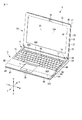
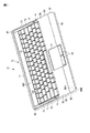
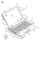
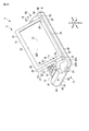
電子機器の一例であるポータブルコンピュータ11は、全体を統括的に制御するCPU等が実装された第1のプリント回路板83が設けられた本体部(第1ユニット)12と、表示画面22Aが設けられた表示部(第2ユニット)13と、本体部12と表示部13とを回動可能に連結した一対のアーム部14と、を備えている。   A portable computer 11 which is an example of an electronic device is provided with a main body (first unit) 12 provided with a first printed circuit board 83 on which a CPU and the like for overall control are mounted, and a display screen 22A. The display unit (second unit) 13 and a pair of arm units 14 that rotatably connect the main body unit 12 and the display unit 13 are provided.

図1、図8、図9に示すように、表示部13は、ディスプレイキャビネット21(表示ケース、第2筐体)と、ディスプレイキャビネット21内に収納されるとともに、外部に露出された表示画面22Aに画像を表示させる表示パネル(表示装置、パネル)22と、表示パネル22よりも外側に設けられ表示パネル22の表面を覆うように外部に露出して設けられたタッチパネル23(タッチセンサ、検知部、検出部、覆い部)と、ディスプレイキャビネット21の一部に取り付けられるカメラ(レンズ、撮像部、撮像装置、電子部品)24と、ディスプレイキャビネット21の上部(表示パネル22よりも本体部から遠い側の端部)でディスプレイキャビネット21内に設けられるアンテナ(送信部、受信部、無線通信部)25と、表示パネル22の下側に隣接して(表示パネル22の近傍に、表示パネル22とは上下方向に並んで)設けられる第2のプリント回路板26と、ディスプレイキャビネット21内に設けられる第2金具27(第2支持部)と、第2金具27に回転可能に支持される第2軸28(第2回転中心、第2支え部)と、第2金具27をディスプレイキャビネット21のカバー33に固定するための固定部材31(ねじ、係合部)と、第2軸28にトルクを付与する第2付与部(第2ブレーキ部、第2抵抗ユニット)42と、を有している。本実施形態では、固定部材31がねじで構成されているが、固定部材31の例としてはこれに限定されるものではなく、ねじ以外に、係合用の爪部、フック、その他の部品・部材等であってもよい。   As shown in FIGS. 1, 8, and 9, the display unit 13 is housed in the display cabinet 21 (display case, second housing) and the display cabinet 21, and the display screen 22 </ b> A exposed to the outside. A display panel (display device, panel) 22 for displaying an image on the touch panel 23 and a touch panel 23 (touch sensor, detector) provided outside the display panel 22 and exposed to the outside so as to cover the surface of the display panel 22 , A detection unit, a cover unit), a camera (lens, an imaging unit, an imaging device, an electronic component) 24 attached to a part of the display cabinet 21, and an upper part of the display cabinet 21 (a side farther from the main body than the display panel 22). And an antenna (transmission unit, reception unit, wireless communication unit) 25 provided in the display cabinet 21 at the end of the display cabinet 21 A second printed circuit board 26 provided adjacent to the lower side of the display panel 22 (in the vicinity of the display panel 22 and lined up and down with the display panel 22), and a second metal fitting 27 provided in the display cabinet 21. (Second support portion), a second shaft 28 (second rotation center, second support portion) rotatably supported by the second metal fitting 27, and the second metal fitting 27 are fixed to the cover 33 of the display cabinet 21. And a second applying portion (second brake portion, second resistance unit) 42 for applying torque to the second shaft 28. In the present embodiment, the fixing member 31 is constituted by a screw. However, the example of the fixing member 31 is not limited to this, and other than the screw, an engaging claw portion, a hook, and other parts / members. Etc.

ディスプレイキャビネット21は、表示パネル22およびタッチパネル23の前方向Fを覆う枠状のマスク(第3ケース)32と、表示パネル22の後方向Bを覆うカバー(第4ケース)33と、を含んでいる。ディスプレイキャビネット21は、一方の端部34(本体部に表示パネル22よりも近い側の端部、一方の辺)と、一方の端部34とは反対側の他方の端部35(表示パネル22よりも本体部に遠い側の端部、他方の辺)と、表示画面22Aが露出される第3面36と、第3面36とは反対側の第4面37と、第3面36および第4面37と交差するとともに一方の端部34および他方の端部35と連続した一対の第2側面38と、を有している。第2軸28は、一方の端部34の近傍(一方の端部34に隣接した位置で、一方の端部34に沿って)に一対に設けられ、表示部13とアーム部(連結部、接続部)14とに亘っている。   The display cabinet 21 includes a frame-shaped mask (third case) 32 that covers the front direction F of the display panel 22 and the touch panel 23, and a cover (fourth case) 33 that covers the rear direction B of the display panel 22. Yes. The display cabinet 21 has one end 34 (an end closer to the main body than the display panel 22, one side) and the other end 35 (the display panel 22 opposite to the one end 34). The other side), the third surface 36 on which the display screen 22A is exposed, the fourth surface 37 opposite to the third surface 36, the third surface 36, and It has a pair of second side surfaces 38 that intersect with the fourth surface 37 and continue to one end 34 and the other end 35. The second shaft 28 is provided in a pair in the vicinity of the one end portion 34 (at a position adjacent to the one end portion 34 and along the one end portion 34), and the display portion 13 and the arm portion (connecting portion, Connection portion) 14.

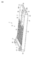
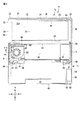
図8に示すように、ディスプレイキャビネット21内には、本体部12の第1のプリント回路板83と表示部13の第2のプリント回路板26とを接続したハーネス41(LCDハーネス、ケーブル)の一部が配置されている。ハーネス41の一部は、ディスプレイキャビネット21の一方の端部34(表示パネル22よりも本体部に近い側の端部)付近からディスプレイキャビネット21内に通されて、第2金具27および固定部材31を迂回しつつ、ほぼ最短距離(一方の端部34に沿って直線的に延びて)で第2のプリント回路板26に接続される。このため、ハーネス41を通すためにディスプレイキャビネット21と表示パネル22との間に無駄なスペースを設ける必要がなく、ディスプレイキャビネット21が極力小さく構成される。   As shown in FIG. 8, a harness 41 (LCD harness, cable) in which the first printed circuit board 83 of the main body 12 and the second printed circuit board 26 of the display unit 13 are connected in the display cabinet 21. Some are arranged. A part of the harness 41 is passed through the display cabinet 21 from the vicinity of one end 34 (the end closer to the main body than the display panel 22) of the display cabinet 21, and the second metal fitting 27 and the fixing member 31 are passed. And is connected to the second printed circuit board 26 at a substantially shortest distance (extending linearly along one end 34). For this reason, it is not necessary to provide a useless space between the display cabinet 21 and the display panel 22 in order to pass the harness 41, and the display cabinet 21 is configured as small as possible.

第2のプリント回路板26は、ケーブル等を介して表示パネル22およびタッチパネル23に接続される。第2のプリント回路板26は、例えば、表示パネル制御用の第1の回路部(回路部品、第1の制御部)26Aと、タッチパネル制御用の第2の回路部(回路部品、第2の制御部)26Bと、を有している。第2付与部42は、第2軸28にトルク(抵抗力)を付与して表示部13に対して第2軸28を回転しにくくし、これによって表示部13を任意の角度で保持・固定することができる。   The second printed circuit board 26 is connected to the display panel 22 and the touch panel 23 via a cable or the like. The second printed circuit board 26 includes, for example, a first circuit unit (circuit component, first control unit) 26A for display panel control and a second circuit unit (circuit component, second control unit for touch panel control). Control unit) 26B. The 2nd provision part 42 gives torque (resistance force) to the 2nd axis | shaft 28, makes it difficult to rotate the 2nd axis | shaft 28 with respect to the display part 13, thereby hold | maintaining and fixing the display part 13 at arbitrary angles. can do.

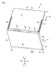
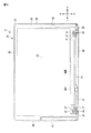
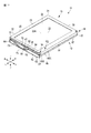
図2に示すように、カバー33には、ディスプレイキャビネット21の第2側面38に沿って延びた溝状(スリット状、長穴状)の第2窪み部(第2開口部、第2凹所)43が、表示部13の左右方向の両端部に一対に設けられており、各第2窪み部43は、カバー33の表面からマスク32方向に向けて窪んでいる。第2窪み部43は、表示画面22Aを本体部12とは反対の方向に向けて表示部13が本体部12に重なるいわゆるタブレット形態(重複形態、折り畳み形態)で、その内側にアーム部14の一部(第2端53、第2部分54、屈曲部55等)を収納することができる(図17参照)。表示パネル22は、例えば、液晶ディスプレイパネルで構成されているが、例えばプラズマディスプレイパネル、有機EL、プラスチックディスプレイパネル、シートディスプレイパネル等、他の種類のディスプレイパネルであってもよい。   As shown in FIG. 2, the cover 33 has a groove-like (slit-like, elongated hole-like) second recess (second opening, second recess) extending along the second side surface 38 of the display cabinet 21. ) 43 are provided in a pair at both ends in the left-right direction of the display unit 13, and each second recess 43 is recessed from the surface of the cover 33 toward the mask 32. The second depression 43 has a so-called tablet form (overlapping form, folded form) in which the display unit 13 overlaps the main body part 12 with the display screen 22A facing in the direction opposite to the main body part 12, and the arm part 14 is provided inside the second depression part 43. A part (the second end 53, the second portion 54, the bent portion 55, etc.) can be accommodated (see FIG. 17). The display panel 22 is configured by, for example, a liquid crystal display panel, but may be another type of display panel such as a plasma display panel, an organic EL, a plastic display panel, a sheet display panel, or the like.

図1に示すように、一対のアーム部14は、表示部13および本体部12の左右両端部の近傍に設けられている。言い換えると、一対のアーム部14は、表示部13の第2側面38および本体部12の第1側面68の近傍に設けられている。このようなアーム部14の配置によって、表示部13および本体部12の内部の部品の実装に制約を与えない設計となっている。   As shown in FIG. 1, the pair of arm portions 14 are provided in the vicinity of the left and right end portions of the display portion 13 and the main body portion 12. In other words, the pair of arm portions 14 are provided in the vicinity of the second side surface 38 of the display portion 13 and the first side surface 68 of the main body portion 12. Such an arrangement of the arm portion 14 is designed not to restrict the mounting of the components inside the display portion 13 and the main body portion 12.

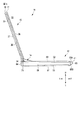
アーム部14の一方は、アーム部14の他方と左右対称形(鏡像)に形成されている。アーム部14のそれぞれは、剛性を有した(剛体からなる)棒状(ポール状、パイプ状、ダクト状)をなしており、より具体的には、第2位置P2にあるときに、全体として後述する第2コネクタ94(部品)のある方向とは反対側に凸になった(突出した、張り出した)弓形(円弧状、アーチ状)の棒状をなしている(図1、図17等参照)。アーム部14は、例えば合成樹脂材料によって断面(切り口)が方形(四角形)で中空(内側に空洞を有する)の形状に形成されている。アーム部14の材質は、合成樹脂材料に限られず、金属やその他の材料(例えば、セラミックス、繊維強化プラスチック(FRP)等)であってもよい。アーム部14の内部にある中空の部分が収納部を構成している。図9に示すように、左側のアーム部14の収納部内に本体部12の第1のプリント回路板83と表示部13の第2のプリント回路板26とを接続したハーネス41(LCDハーネス、ケーブル)が通される。右側のアーム部14の収納部内には、本体部12の第1のプリント回路板83と表示部13のカメラ24とを接続する第1ケーブル44と、本体部12の第1のプリント回路板83と表示部13のアンテナ25とを接続する第2ケーブル45と、が通される。図10に示すように、例えば、各アーム部14は、断面「C」字(「U」字)になった第1部材(本体部材)46と、第1部材46の内側の収納部(開口)を密閉(閉塞)するように第1部材46に嵌る(嵌合する、係合する)蓋状(板状、栓状)の第2部材(嵌合部材、係合部材、板材)47と、を有している。   One of the arm portions 14 is formed in a symmetrical shape (mirror image) with the other of the arm portions 14. Each of the arm portions 14 has a rigid (made of a rigid body) rod shape (pole shape, pipe shape, duct shape), and more specifically, when the arm portion 14 is at the second position P2, the whole will be described later. The second connector 94 (part) to be formed has an arcuate (arc-like, arch-like) bar shape that is convex (protruded, overhangs) on the opposite side of the direction in which the second connector 94 (part) is located (see FIGS. 1, 17, etc.) . The arm portion 14 is formed, for example, of a synthetic resin material into a shape having a square cross section (cut) and a hollow shape (having a hollow inside). The material of the arm portion 14 is not limited to a synthetic resin material, and may be a metal or other materials (for example, ceramics, fiber reinforced plastic (FRP), etc.). A hollow portion inside the arm portion 14 constitutes a storage portion. As shown in FIG. 9, a harness 41 (LCD harness, cable) in which the first printed circuit board 83 of the main body 12 and the second printed circuit board 26 of the display unit 13 are connected in the storage part of the left arm part 14. ) Is passed. In the storage section of the right arm section 14, a first cable 44 that connects the first printed circuit board 83 of the main body section 12 and the camera 24 of the display section 13, and a first printed circuit board 83 of the main body section 12. And a second cable 45 connecting the antenna 25 of the display unit 13 is passed. As shown in FIG. 10, for example, each arm portion 14 includes a first member (main body member) 46 having a cross section “C” shape (“U” shape), and a storage portion (opening) inside the first member 46. A second member (a fitting member, an engaging member, a plate material) 47 of a lid shape (plate shape, plug shape) that fits (fits, engages) the first member 46 so as to be sealed (closed) ,have.

図6等に示すように、アーム部14のそれぞれは、本体部12の第1軸(第1回転中心、第1支え部)81に対して固定的(回転しないように)に設けられた第1端(第1保持部)51と、第1端51から直線的に(まっすぐに)延びる第1部分52と、表示部13の第2軸28に対して固定的(回転しないように)に設けられた第2端(第2保持部)53と、第2端53から直線的に延びる第2部分54と、第1部分52と第2部分54とを連結した屈曲部(湾曲部、角部、曲げ部)55と、を有している(図6では、第1軸81および第2軸28の一部を示しており、実際の第1軸81および第2軸28は図7、図8に示すような長さ(アーム部の左右方向の幅よりも長い寸法、第1窪み部72の左右方向の幅よりも長い寸法、本体部12の第1側面68から第1金具95にまで至る寸法)を有する。なお、アーム部14のそれぞれは、第1軸81および第2軸28に対して固定的に設けられている。しかしながら、第1軸81は、本体部12のそれ以外の部分に対して回転可能に設けられ、第2軸28は、表示部13のそれ以外の部分に対して回転可能に設けられているため、アーム部14のそれぞれは、実質的に第1軸81周りおよび第2軸28周りに回動可能となっている。   As shown in FIG. 6 and the like, each of the arm parts 14 is fixedly provided (so as not to rotate) with respect to the first shaft (first rotation center, first support part) 81 of the main body part 12. One end (first holding portion) 51, a first portion 52 extending linearly (straightly) from the first end 51, and fixed to the second axis 28 of the display portion 13 (so as not to rotate). A second end (second holding portion) 53 provided, a second portion 54 linearly extending from the second end 53, and a bent portion (curved portion, corner) connecting the first portion 52 and the second portion 54. (FIG. 6 shows a part of the first shaft 81 and the second shaft 28, and the actual first shaft 81 and the second shaft 28 are shown in FIG. The length as shown in FIG. 8 (dimension longer than the width of the arm portion in the left-right direction, longer than the width of the first recess 72 in the left-right direction, the main body 1 Of the first side surface 68 to the first metal fitting 95. Each of the arm portions 14 is fixedly provided with respect to the first shaft 81 and the second shaft 28. The first shaft 81 is provided so as to be rotatable with respect to other portions of the main body portion 12, and the second shaft 28 is provided so as to be rotatable with respect to other portions of the display portion 13. Each of 14 is substantially rotatable around the first axis 81 and the second axis 28.

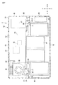
図1、図4、図5に示すように、本体部12は、例えば、合成樹脂によって箱状(容器状)に形成される本体キャビネット61(本体ケース、第1筐体)を有している。本体キャビネット61は、上側半部を構成した第1ケース62と、下側半部を構成した第2ケース63とを接合して形成されている。本体キャビネット61は、後側の第1端部64(第1辺、後面)と、第1端部64とは反対側(前側)の第2端部65(第2辺、前面)と、表示部13に対向する第1面66(上面)と、第1面66とは反対側の第2面67と、第1面66および第2面67とそれぞれ交差(直交)するとともに第1端部64および第2端部65と連続した一対の第1側面68と、第1面66上で第1端部64の近傍に設けられ、表面から略半円(円弧状)に窪んだ凹部71と、後述するキーボード(操作部、入力部)76から外れた位置で第1面66から窪んで設けられる一対の第1窪み部(第1開口部、第1凹所)72と、を有している。図4等に示すように、第2端部65は、第1面66側に設けられ第1面66に対して斜めになった(交差した、勾配をなした)第1傾斜部65Aと、第2面67側に設けられ第2面67に対して斜めになった(交差した、勾配をなした)第2傾斜部65Bと、を有している。このため、第2端部65は、本体部12の他の部分よりも厚み寸法が小さくなっている。なお、本体キャビネット61とディスプレイキャビネット21により、ポータブルコンピュータ11の筐体が構成されている。   As shown in FIGS. 1, 4, and 5, the main body 12 includes a main body cabinet 61 (main body case, first housing) formed in a box shape (container shape) from, for example, a synthetic resin. . The main body cabinet 61 is formed by joining a first case 62 that constitutes the upper half and a second case 63 that constitutes the lower half. The main body cabinet 61 includes a first end portion 64 (first side, rear surface) on the rear side, a second end portion 65 (second side, front surface) on the opposite side (front side) to the first end portion 64, and a display. The first surface 66 (upper surface) facing the portion 13, the second surface 67 opposite to the first surface 66, and the first surface 66 and the second surface 67 intersect (orthogonal) with each other and the first end portion 64 and a pair of first side surfaces 68 that are continuous with the second end portion 65, and a recess 71 that is provided in the vicinity of the first end portion 64 on the first surface 66 and that is recessed in a substantially semicircle (arc shape) from the surface, A pair of first recesses (first opening, first recess) 72 provided to be recessed from the first surface 66 at a position away from a keyboard (operation unit, input unit) 76 described later. Yes. As shown in FIG. 4 and the like, the second end portion 65 is provided on the first surface 66 side and is inclined with respect to the first surface 66 (intersecting and making a gradient), And a second inclined portion 65B that is provided on the second surface 67 side and is inclined with respect to the second surface 67 (intersecting and forming a gradient). For this reason, the second end portion 65 has a smaller thickness dimension than the other portions of the main body portion 12. The main body cabinet 61 and the display cabinet 21 constitute a casing of the portable computer 11.

図5等に示すように、本実施形態では、第1窪み部72は、(第2コネクタ94およびタッチパッド77よりも)本体部12の後方に寄って本体部12の左右方向の両端部に一対に設けられている。各第1窪み部72は、本体キャビネット61の第1側面68に沿って溝状に延びており、アーム部14の屈曲部55およびその他の部分に沿って窪んでいる。各第1窪み部72は、後述する第1位置P1にあるアーム部14が当接する第1斜面部(第1坂部、第1勾配)73と、第2位置P2にあるアーム部14に沿って斜めになった第2斜面部(第2坂部、第2勾配)74と、第1斜面部73と第2斜面部74との間に設けられアーム部14の屈曲部55が当接する底部(中間部、当接部)75と、を含んでいる。各第1窪み部72は、第1位置P1にあるアーム部14をその内側に収納することができる。   As shown in FIG. 5 and the like, in the present embodiment, the first indented portion 72 is closer to the rear of the main body portion 12 (than the second connector 94 and the touch pad 77) and at both end portions of the main body portion 12 in the left-right direction. It is provided in a pair. Each first recess 72 extends in a groove shape along the first side surface 68 of the main body cabinet 61 and is recessed along the bent portion 55 and other portions of the arm portion 14. Each first recess 72 is along a first slope portion (first slope portion, first slope) 73 with which an arm portion 14 at a first position P1 (described later) abuts and an arm portion 14 at a second position P2. An inclined second slope portion (second slope portion, second slope) 74 and a bottom portion (intermediate portion) provided between the first slope portion 73 and the second slope portion 74 and the bent portion 55 of the arm portion 14 abuts. Part, abutting part) 75. Each first recess 72 can accommodate the arm portion 14 at the first position P1 inside.

図1、図7等に示すように、本体部12は、本体キャビネット61の外側に取り付けられるキーボード76と、本体キャビネット61の外側に取り付けられるタッチパッド(タッチセンサ、接触感知部、ポインティングデバイス)77およびボタン(操作部、タッチパッド用ボタン)78と、第1端部(第1辺、後面)64と第2端部(第2辺、前面)65との間に設けられた第1軸81と、本体キャビネット61の内側で(メインバッテリ87よりも)後方寄りに設けられるとともにCPU等の回路部品82が実装された第1のプリント回路板83と、回路部品82を冷却するように一方の端部で回路部品82と熱的に接続されたヒートパイプ(熱輸送手段、熱輸送部)84と、ヒートパイプ84の他方の端部に固定されるフィンユニット(フィン、複数のフィン、放熱板)85と、本体キャビネット61の内側に設けられヒートパイプ84およびフィンユニット85の冷却を促進するファンユニット(ファン、送風部、送風装置)86と、本体キャビネット61の内側に設けられるメインバッテリ87(第1バッテリ)およびサブバッテリ88(第2バッテリ)と、本体キャビネット61の内側で第1のプリント回路板83の近傍に設けられるとともに第1のプリント回路板83とケーブル等を介して接続された記憶装置(記憶手段、ストレージデバイス)91と、第1のプリント回路板83に設けられ本体部12後方(第1端部64)で外界に露出された外部接続用の第1コネクタ92と、本体キャビネット61の内側前方寄りで第1のプリント回路板83と分離して設けられるとともに第1のプリント回路板83とフレキシブルケーブル等で接続されたコネクタ用の基板93と、コネクタ用の基板93上に設けられ第1側面68で外界に露出された外部接続用の第2コネクタ94(部品)と、第1軸81を回転可能に支持する第1金具95(第1支持部)と、第1金具95を本体キャビネット61に固定する固定部材31(ねじ、係合部)と、第1軸81にトルクを付与する第1付与部(第1ブレーキ部、第1抵抗ユニット)96と、を有する。本実施形態では、固定部材31がねじで構成されているが、固定部材31の例としてはこれに限定されるものではなく、ねじ以外に、係合用の爪部、フック、その他の部品・部材等であってもよい。   As shown in FIGS. 1 and 7, the main body 12 includes a keyboard 76 attached to the outside of the main body cabinet 61 and a touch pad (touch sensor, contact sensing unit, pointing device) 77 attached to the outside of the main body cabinet 61. And a button (operation unit, touchpad button) 78, a first shaft 81 provided between a first end (first side, rear surface) 64 and a second end (second side, front surface) 65. A first printed circuit board 83 provided on the inner side of the main body cabinet 61 (relative to the main battery 87) and mounted with a circuit component 82 such as a CPU, and one of the circuit components 82 so as to cool the circuit component 82. A heat pipe (heat transport means, heat transport portion) 84 thermally connected to the circuit component 82 at the end, and a fin unit fixed to the other end of the heat pipe 84 Fins, a plurality of fins, a heat radiating plate) 85, a fan unit (fan, air blower, air blower) 86 that is provided inside the main body cabinet 61 and promotes cooling of the heat pipe 84 and the fin unit 85, A main battery 87 (first battery) and a sub-battery 88 (second battery) provided on the inside, a first printed circuit board 83 provided in the vicinity of the first printed circuit board 83 inside the main body cabinet 61, and A storage device (storage means, storage device) 91 connected via a cable or the like, and an external connection provided on the first printed circuit board 83 and exposed to the outside at the back of the main body 12 (first end 64) The first connector 92 and the first printed circuit board 83 are provided near the inner front side of the main body cabinet 61. And a connector board 93 connected to the first printed circuit board 83 with a flexible cable and the like, and a second connector for external connection provided on the connector board 93 and exposed to the outside at the first side surface 68. 94 (parts), a first metal fitting 95 (first support portion) that rotatably supports the first shaft 81, and a fixing member 31 (screw, engagement portion) that fixes the first metal fitting 95 to the main body cabinet 61. And a first applying portion (first brake portion, first resistance unit) 96 that applies torque to the first shaft 81. In the present embodiment, the fixing member 31 is constituted by a screw. However, the example of the fixing member 31 is not limited to this, and other than the screw, an engaging claw portion, a hook, and other parts / members. Etc.

第2コネクタ94は、屈曲部55で迂回された(屈曲部55で避けた、屈曲部55から外れた)位置(箇所、部位、地点)で本体部12(の第1側面68の近傍)に設けられる部品の一例であるが、部品の例としてはこれに限定されない。部品は、ハードディスクドライブやSSD等の記憶装置、バッテリ、回路部品を実装したプリント回路板、ヒートパイプやフィンユニット、ファンユニットを含む冷却装置、液晶ディスプレイ等の表示パネル、タッチパネル、アンテナ、カメラ、スピーカ等の音響部品、操作用のボタン、各種メモリーカードおよび各種認証用カードのスロット、無線LAN等の通信用モジュール、およびその他の部品であってもよい。   The second connector 94 is located at the main body 12 (in the vicinity of the first side face 68) at a position (location, part, point) detoured by the bent portion 55 (apart from the bent portion 55, avoided by the bent portion 55). Although it is an example of the components provided, it is not limited to this as an example of components. Components include storage devices such as hard disk drives and SSDs, batteries, printed circuit boards mounted with circuit components, cooling devices including heat pipes and fin units, fan units, display panels such as liquid crystal displays, touch panels, antennas, cameras, and speakers. Such as acoustic components such as, buttons for operation, slots for various memory cards and various authentication cards, communication modules such as a wireless LAN, and other components.

第1軸81は、本体部12の前後方向の中程(中間部、中央部)に一対に設けられており、例えば、キーボード76の前端76A或いはタッチパッド77よりも後側で、キーボード76の後端76Bよりも前側に設けられている。第1軸81は、第1面66と第2面67との間の位置に設けられている(図16等参照)。記憶装置91は、例えばハードディスクドライブ(HDD)で構成されているが、SSD(Solid State Drive)やそれ以外のフラッシュメモリー等の他の記憶手段であってもよい。第1付与部96は、アーム部14が、後述する第1位置P1および第2位置P2にあるときに、第1軸81にトルク(抵抗力)を付与して第1軸81を回転しにくくできる。   The first shaft 81 is provided in a pair in the middle (intermediate portion, center portion) in the front-rear direction of the main body portion 12. For example, the first shaft 81 is rearward of the front end 76 </ b> A of the keyboard 76 or the touch pad 77. It is provided in front of the rear end 76B. The first shaft 81 is provided at a position between the first surface 66 and the second surface 67 (see FIG. 16 and the like). The storage device 91 is composed of, for example, a hard disk drive (HDD), but may be other storage means such as an SSD (Solid State Drive) or other flash memory. The first applying portion 96 is difficult to rotate the first shaft 81 by applying torque (resistance force) to the first shaft 81 when the arm portion 14 is in a first position P1 and a second position P2 described later. it can.

続いて、図11から図17を参照してポータブルコンピュータ11の形態を変更する際の動作について説明する。   Next, an operation when changing the form of the portable computer 11 will be described with reference to FIGS. 11 to 17.

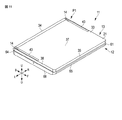
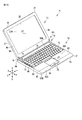
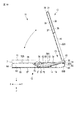
図11では、表示画面22Aが本体部12の方向を向いた状態(対向状態)で、表示部13が本体部12に重なった状態、いわゆる可搬形態(表示部13が閉じた閉形態)となっている。そして、第2軸28周りに表示部13を回転させると、図12に示すように、ノートブック型のポータブルコンピュータ11の通常(表示部13が開いた開形態)の使用形態となる。これらの状態では、アーム部14は第1位置P1と呼ばれる位置にあり、この第1位置P1では表示部13の第2軸28は本体部12の第1端部64の近傍に位置している。図16に示すように、アーム部14が第1位置P1にあるときには、表示部13の一方の端部34は凹部(凹面、凹所)71内に嵌って(嵌合して、係合して)これに収納される。このとき、表示部13が本体部12の第1端部64よりも後ろ側(後方、奥側)には回り込まない設計となっているため、第1端部64において第1コネクタ92等の実装スペース(領域、設置場所)が確保される。   In FIG. 11, the display screen 22 </ b> A faces the direction of the main body 12 (opposite state), the display 13 is overlapped with the main body 12, a so-called portable form (closed form with the display 13 closed) and It has become. Then, when the display unit 13 is rotated about the second axis 28, as shown in FIG. 12, a normal usage pattern of the notebook portable computer 11 (open configuration in which the display unit 13 is opened) is obtained. In these states, the arm portion 14 is in a position called the first position P1, and the second shaft 28 of the display portion 13 is located in the vicinity of the first end portion 64 of the main body portion 12 at the first position P1. . As shown in FIG. 16, when the arm portion 14 is in the first position P1, one end portion 34 of the display portion 13 is fitted (fitted and engaged) in a concave portion (concave surface, concave portion) 71. It is stored in this. At this time, since the display unit 13 is designed not to wrap around behind the first end portion 64 of the main body portion 12 (rear side, rear side), the first connector 92 and the like are mounted at the first end portion 64. Space (area, installation location) is secured.

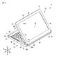
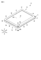
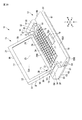
そして、この状態から図13に示すように、ユーザの手で表示部13等を把持(持って、掴んで)してアーム部14を前方向に回動させると、表示部13の第2軸28が本体部12の第2端部65の近傍(付近)に位置(隣接して配置)される。このとき、図14に示す状態となり、この位置のアーム部14の位置を第2位置P2と呼ぶ。図14に示す状態では、机上で使用する際の形態であり、いわゆるタブレット形態(机上形態)の一つである(第1のタブレット形態)。さらに、この状態から、表示部13を第2軸28周りに回転させると、図15に示すように、表示画面22Aが本体部12とは反対の方向を向いた状態で、表示部13が本体部12に重なった状態、つまりキーボード76が隠れた(覆われた、収納された)タブレット形態となる(第2のタブレット形態)。この形態では、主としてユーザが手に持って使用したり、机上で使用したりすることを想定している。図17に示すように、このタブレット形態では、表示部13の第2軸28は、本体部12の第2端部65(第1傾斜部65A)に重なっている。このため、本体部12の厚み方向における寸法および表示部13の厚み方向における寸法の大きくなりやすい軸(第2軸28)周りで寸法(長さ、幅)が大きくなることが防止されている。また、アーム部14が第2位置P2にあるときには、第2コネクタ94(部品)が屈曲部55によって迂回されて(屈曲部55で避けて、屈曲部55から外れて)いるため、アーム部14が第2コネクタ94と干渉する(当たる、ぶつかる、邪魔になる)ことがない(図1、図17等参照)。   Then, from this state, as shown in FIG. 13, when the display unit 13 is gripped (held and held) by the user's hand and the arm unit 14 is rotated forward, the second axis of the display unit 13 is moved. 28 is positioned (disposed adjacently) near (near) the second end 65 of the main body 12. At this time, the state shown in FIG. 14 is obtained, and the position of the arm portion 14 at this position is referred to as a second position P2. In the state shown in FIG. 14, it is a form at the time of using on a desk, and is one of what is called a tablet form (desk form) (1st tablet form). Further, when the display unit 13 is rotated around the second axis 28 from this state, the display unit 13 is in the state in which the display screen 22A faces in the direction opposite to the main unit 12 as shown in FIG. The tablet 12 is in a state of being overlapped with the portion 12, that is, the keyboard 76 is hidden (covered and stored) (second tablet form). In this form, it is assumed that the user mainly uses it in his / her hand or uses it on a desk. As shown in FIG. 17, in the tablet form, the second shaft 28 of the display unit 13 overlaps the second end 65 (first inclined portion 65 </ b> A) of the main body 12. For this reason, it is prevented that the dimension (length, width) increases around the axis (second axis 28) in which the dimension in the thickness direction of the main body 12 and the dimension in the thickness direction of the display unit 13 tend to increase. Further, when the arm portion 14 is in the second position P2, the second connector 94 (component) is bypassed by the bent portion 55 (avoided by the bent portion 55 and removed from the bent portion 55). Does not interfere with the second connector 94 (striking, colliding, or obstructing) (see FIGS. 1, 17, etc.).

第1の実施形態によれば、ポータブルコンピュータ11は、第1端部64と、第1端部64とは反対側の第2端部65と、第1端部64と第2端部65との間に位置した第1軸81と、を有する本体部12と、本体部12に近い側の端部の近傍に位置する第2軸28と、表示画面22Aと、を有する表示部13と、第1軸81と第2軸28とを連結するとともに途中に屈曲部(曲げ部)55を有し、第2軸28を第1端部64の近傍(付近)に位置させた第1位置P1と、第2軸28を第2端部65の近傍に位置させた第2位置P2と、の間で回動するように第1軸81周りに回動可能なアーム部14と、アーム部14が第2位置P2にあるときに、屈曲部55で迂回された位置(屈曲部55で避けた位置、屈曲部55から外れた位置)で本体部12に設けられた部品(部材、装置、器具)と、を備える。   According to the first embodiment, the portable computer 11 includes a first end 64, a second end 65 opposite to the first end 64, a first end 64, and a second end 65. A display unit 13 having a main body portion 12 having a first shaft 81 positioned between the second shaft 28 and a display screen 22A, a second shaft 28 located in the vicinity of the end portion close to the main body portion 12, and A first position P1 that connects the first shaft 81 and the second shaft 28, has a bent portion (bent portion) 55 in the middle, and positions the second shaft 28 in the vicinity (near the first end portion 64). And an arm portion 14 rotatable about the first shaft 81 so as to rotate between a second position P2 where the second shaft 28 is positioned in the vicinity of the second end portion 65, and an arm portion 14 Is located at the second position P2 at a position detoured by the bent portion 55 (a position avoided by the bent portion 55, a position deviated from the bent portion 55). It comprises parts which are provided in section 12 (member, apparatus, instruments) and, the.

この構成によれば、従来形のポータブルコンピュータに比して、アーム部14および第1軸81を追加するわずかな変更のみで通常の使用形態といわゆるタブレット形態の両方を実現でき、ユーザの利便性を向上できるとともに、ポータブルコンピュータ11の重量増加および部品点数の増加を防止できる。また、部品が屈曲部55で迂回されているため、第2位置P2にアーム部14が位置したときに、部品とアーム部14とが干渉することがない。これによって、部品の設置スペースを確保して本体部12内のスペースを有効活用できるとともに、本体部12の厚み寸法を低減して薄型化・小型化を実現できる。   According to this configuration, compared with a conventional portable computer, both a normal use form and a so-called tablet form can be realized with only a slight change by adding the arm portion 14 and the first shaft 81, and this is convenient for the user. And an increase in the weight of the portable computer 11 and an increase in the number of parts can be prevented. Further, since the component is detoured by the bent portion 55, the component and the arm portion 14 do not interfere when the arm portion 14 is positioned at the second position P2. As a result, it is possible to secure the installation space for the components and effectively use the space in the main body portion 12, and to reduce the thickness dimension of the main body portion 12 to realize a reduction in thickness and size.

第2位置P2にあるアーム部14は、部品とは反対側に向けて凸になる(突出した、張り出した)ように曲がって(屈曲して、湾曲して)いる。これによれば、第2位置P2にあるアーム部14が部品と干渉することがより一層防止され、部品の実装スペースの確保と本体部12の小型化とが実現できる。   The arm portion 14 at the second position P2 is bent (bent and curved) so as to protrude toward the side opposite to the component (projected or overhanged). According to this, the arm portion 14 at the second position P2 is further prevented from interfering with the component, and it is possible to realize the mounting space for the component and the miniaturization of the main body portion 12.

本体部12は、窪み部(開口部、凹所)を有し、該窪み部は、屈曲部55に沿って窪むとともに、アーム部14が第1位置P1にあるときにアーム部14を収納できる。この構成によれば、アーム部14が第1位置P1にあるときに、アーム部14のぐらつきを防止してアーム部14の位置を安定させることができ、その結果表示部13のぐらつきを防止できる。また、アーム部14を収納して目立たなくすることができ、ポータブルコンピュータ11の体裁を良好にすることができる。さらに、アーム部14の回動角度を窪み部で規制できるため、別途にアーム部14の回動角度を規制する部品が不要である。   The main body 12 has a recess (opening, recess), the recess is recessed along the bent portion 55, and can accommodate the arm 14 when the arm 14 is in the first position P1. . According to this structure, when the arm part 14 exists in the 1st position P1, the wobble of the arm part 14 can be prevented and the position of the arm part 14 can be stabilized, As a result, the wobble of the display part 13 can be prevented. . Further, the arm portion 14 can be housed so as to be inconspicuous, and the appearance of the portable computer 11 can be improved. Furthermore, since the rotation angle of the arm part 14 can be regulated by the recess part, a component for regulating the rotation angle of the arm part 14 is unnecessary.

ポータブルコンピュータ11は、第1位置P1および第2位置P2にあるアーム部14に所定のトルクを付与してアーム部14を第1軸81周りに回動しにくくする付与部(ブレーキ部、抵抗ユニット)を備える。この構成によれば、アーム部14が第1位置P1および第2位置P2にあるときに、アーム部14が浮き上がる(第1位置P1および第2位置P2から移動する)ことが防止され、表示部13がぐらついてしまうことを防止できる。   The portable computer 11 applies a predetermined torque to the arm part 14 at the first position P1 and the second position P2 to make it difficult for the arm part 14 to turn around the first shaft 81 (brake part, resistance unit). ). According to this configuration, when the arm unit 14 is at the first position P1 and the second position P2, the arm unit 14 is prevented from floating (moving from the first position P1 and the second position P2), and the display unit 13 can be prevented from wobbling.

アーム部14は、本体部12の表示部13に対向する第1面66に沿って曲がるとともに、第2位置P2にあるときに第1面66上に載る。この構成によれば、アーム部14が第2位置P2にあるときに表示部13のぐらつきを防止できる。また、第2位置P2にあるアーム部14が嵌る窪みなどを設ける必要がない分、第1面66の内側にある本体部12内部の部品の実装スペースを確保して、高密度実装を実現できる。   The arm unit 14 bends along the first surface 66 facing the display unit 13 of the main body unit 12 and rests on the first surface 66 when in the second position P2. According to this configuration, the wobbling of the display unit 13 can be prevented when the arm unit 14 is at the second position P2. Further, since there is no need to provide a recess or the like in which the arm portion 14 at the second position P2 is fitted, a mounting space for components inside the main body portion 12 inside the first surface 66 can be secured and high-density mounting can be realized. .

第2端部65は、本体部12の他の部分よりも厚み寸法が小さくなっており、第2軸28は、アーム部14が第2位置P2にあるときに第2端部65に重なる。この構成によれば、アーム部14が第2位置P2にあるときに、第2軸28付近において厚み寸法が大きくなってしまうことを防止して、ポータブルコンピュータ11の薄型化を図ることができる。   The second end portion 65 has a smaller thickness than other portions of the main body portion 12, and the second shaft 28 overlaps the second end portion 65 when the arm portion 14 is at the second position P2. According to this configuration, the thickness of the portable computer 11 can be reduced by preventing the thickness dimension from increasing in the vicinity of the second shaft 28 when the arm portion 14 is at the second position P2.

本体部12は、アーム部14が第1位置P1にあるときに、表示部13の本体部12に近い側の端部を収納する凹部71を有する。これにより、アーム部14が第1位置P1にあるときに表示部13のぐらつきをより一層防止できる。   The main body 12 has a recess 71 that houses the end of the display unit 13 on the side close to the main body 12 when the arm 14 is at the first position P1. Thereby, when the arm part 14 exists in the 1st position P1, the wobble of the display part 13 can be prevented further.

本体部12は、表示部13に対向するとともにキーボード76が設けられた第1面66と、第1面66とは反対側の第2面67と、キーボード76を外れた位置で本体部12に設けられるとともに、第1位置P1にあるアーム部14を収納できる窪み部と、を有し、第1軸81は、第1面66と第2面67との間の位置に設けられ、アーム部14が第1位置P1にあるときに、表示部13はキーボード76よりも後側に位置される。この構成によれば、第1位置P1にあるときにアーム部14は窪み部に収納され、第1軸81、アーム部14、および表示部13がキーボード操作時に邪魔になることがなく、キーボード76の操作性を良好にできる。   The main body portion 12 faces the display portion 13 and has a first surface 66 provided with a keyboard 76, a second surface 67 opposite to the first surface 66, and the main body portion 12 at a position away from the keyboard 76. And a hollow portion that can accommodate the arm portion 14 at the first position P1, and the first shaft 81 is provided at a position between the first surface 66 and the second surface 67. When 14 is in the first position P <b> 1, the display unit 13 is positioned behind the keyboard 76. According to this configuration, when the arm portion 14 is in the first position P1, the arm portion 14 is accommodated in the recess portion, and the first shaft 81, the arm portion 14, and the display portion 13 are not obstructed when the keyboard is operated. The operability can be improved.

続いて、図18、図19を参照して、電子機器の第2の実施形態について説明する。第2の実施形態の電子機器の一例であるポータブルコンピュータ11は、一対のアーム部(連結部、接続部)14および第1窪み部72の構成および第2コネクタ94の位置が第1の実施形態と異なっているが、他の部分で第1の実施形態と概ね共通している。このため、主として第1の実施形態と異なる部分について説明し、共通する箇所については共通の符号を付して説明を省略する。   Next, a second embodiment of the electronic device will be described with reference to FIGS. The portable computer 11, which is an example of the electronic apparatus of the second embodiment, has a configuration of a pair of arm portions (connecting portions, connection portions) 14 and a first recess portion 72 and a position of the second connector 94 in the first embodiment. The other parts are generally the same as those of the first embodiment. For this reason, a different part from 1st Embodiment is mainly demonstrated, a common code | symbol is attached | subjected about a common location, and description is abbreviate | omitted.

第2の実施形態では、アーム部(連結部、接続部)14の一方が、アーム部14の他方と左右対称形(鏡像)であることは第1の実施形態と同様である。しかしながら、一対のアーム部14は、第1の実施形態のアーム部14とは逆向きに凸になるように曲がっている。   In the second embodiment, it is the same as in the first embodiment that one of the arm portions (coupling portion, connection portion) 14 is bilaterally symmetrical (mirror image) with the other of the arm portions 14. However, the pair of arm portions 14 are bent so as to protrude in the opposite direction to the arm portion 14 of the first embodiment.

アーム部14のそれぞれは、剛性を有した(剛体からなる)棒状(ポール状、パイプ状、ダクト状)をなしており、より具体的には、第1位置P1にあるときに、全体として後述する第2コネクタ94(部品)のある方向とは反対側に凸になった(突出した、張り出した)弓形(円弧状、アーチ状)の棒状をなしている。アーム部14は、例えば合成樹脂材料によって断面(切り口)が方形(四角形)で中空(内側に空洞を有する)の形状に形成されている。左側のアーム部14の内部の収納部内に本体部12の第1のプリント回路板83と表示部13の第2のプリント回路板26とを接続したハーネス41(LCDハーネス、ケーブル)が通される。右側のアーム部14の内部の収納部内には、本体部12の第1のプリント回路板83と表示部13のカメラ24とを接続する第1ケーブル44と、本体部12の第1のプリント回路板83と表示部13のアンテナ25とを接続する第2ケーブル45と、が通される。   Each of the arm portions 14 has a rigid rod shape (made of a rigid body) (pole shape, pipe shape, duct shape), and more specifically, when it is at the first position P1, as a whole. The second connector 94 (part) is formed in an arcuate (arc-shaped, arch-shaped) bar shape that is convex (protruded and overhangs) on the opposite side to the direction in which the second connector 94 (part) is located. The arm portion 14 is formed, for example, of a synthetic resin material into a shape having a square cross section (cut) and a hollow shape (having a hollow inside). A harness 41 (LCD harness, cable) connecting the first printed circuit board 83 of the main body section 12 and the second printed circuit board 26 of the display section 13 is passed through the storage section inside the left arm section 14. . In the storage portion inside the right arm portion 14, a first cable 44 that connects the first printed circuit board 83 of the main body portion 12 and the camera 24 of the display portion 13, and a first printed circuit of the main body portion 12. A second cable 45 connecting the plate 83 and the antenna 25 of the display unit 13 is passed through.

アーム部14のそれぞれは、本体部12の第1軸(第1回転中心、第1支え部)81に対して固定的(回転しないように)に設けられた第1端(第1保持部)51と、第1端51から直線的(まっすぐに)に延びる第1部分52と、表示部13の第2軸28(第2回転中心、第2支え部)に対して固定的(回転しないように)に設けられた第2端(第2保持部)53と、第2端53から直線的に延びる第2部分54と、第1部分52と第2部分54とを連結した屈曲部(湾曲部、角部、曲げ部)55と、を有している。なお、第1軸81は、本体部12のそれ以外の部分に対して回転可能に設けられ、第2軸28は、表示部13のそれ以外の部分に対して回転可能に設けられているため、アーム部14のそれぞれは、実質的に第1軸81周りおよび第2軸28周りに回動可能である。   Each of the arm portions 14 has a first end (first holding portion) provided fixedly (so as not to rotate) with respect to a first shaft (first rotation center, first support portion) 81 of the main body portion 12. 51, the first portion 52 that extends linearly (straightly) from the first end 51, and the second axis 28 (second rotation center, second support portion) of the display unit 13 (not to rotate). A second end (second holding portion) 53 provided at the second end 53, a second portion 54 linearly extending from the second end 53, and a bent portion (curved portion) connecting the first portion 52 and the second portion 54. Part, corner part, bending part) 55. The first shaft 81 is provided so as to be rotatable with respect to other portions of the main body portion 12, and the second shaft 28 is provided so as to be rotatable with respect to other portions of the display portion 13. Each of the arm portions 14 is substantially rotatable around the first axis 81 and the second axis 28.

本体部12は、例えば、合成樹脂によって箱状(容器状)に形成される本体キャビネット61(本体ケース、第1筐体)を有している。本体キャビネット61は、後側の第1端部64(第1辺、後面)と、前側の第2端部65(第2辺、前面)と、表示部13に対向する第1面66(上面)と、第1面66とは反対側の第2面67と、第1面66および第2面67とそれぞれ交差(直交)するとともに第1端部64および第2端部65と連続した一対の第1側面68と、第1面66上で第1端部64の近傍に設けられ、表面から略半円(円弧状)に窪んだ凹部71と、後述するキーボード(操作部、入力部)76から外れた位置で第1面66から窪んで設けられる一対の第1窪み部(第1開口部、第1凹所)72と、を有している。第2端部65は、第1面66側に設けられ第1面66に対して斜めになった(交差した、勾配をなした)第1傾斜部65Aと、第2面67側に設けられ第2面67に対して斜めになった(交差した、勾配をなした)第2傾斜部65Bと、を有している。このため、第2端部65は、本体部12の他の部分よりも厚み寸法が小さくなっている。なお、本体キャビネット61とディスプレイキャビネット21により、ポータブルコンピュータ11の筐体が構成されている。   The main body 12 includes, for example, a main body cabinet 61 (main body case, first housing) formed in a box shape (container shape) from a synthetic resin. The main body cabinet 61 includes a first end portion 64 (first side, rear surface) on the rear side, a second end portion 65 (second side, front surface) on the front side, and a first surface 66 (upper surface) facing the display unit 13. ), A second surface 67 opposite to the first surface 66, and a pair of first surfaces 66 and second surfaces 67 that intersect (orthogonally) and continue to the first end 64 and the second end 65, respectively. A first side surface 68, a recess portion 71 provided on the first surface 66 in the vicinity of the first end portion 64 and recessed in a substantially semicircle (arc shape) from the surface, and a keyboard (operation unit, input unit) described later. And a pair of first recesses (first opening, first recess) 72 provided to be recessed from the first surface 66 at a position deviated from 76. The second end portion 65 is provided on the first surface 66 side, and is provided on the second surface 67 side and the first inclined portion 65A that is inclined (intersecting and forming a gradient) with respect to the first surface 66. A second inclined portion 65B that is inclined with respect to the second surface 67 (intersecting and forming a gradient). For this reason, the second end portion 65 has a smaller thickness dimension than the other portions of the main body portion 12. The main body cabinet 61 and the display cabinet 21 constitute a casing of the portable computer 11.

図18等に示すように、本実施形態では、第1窪み部72は、(第2コネクタ94よりも)本体部12の前方に寄って本体部12の左右方向の両端部に一対に設けられている。各第1窪み部72は、本体キャビネット61の第1側面68に沿って溝状に延びており、アーム部14の屈曲部55およびその他の部分に沿って窪んでいる。第1窪み部72は、後述する第1位置P1にあるアーム部14に沿って斜めになった第1斜面部(第1坂部、第1勾配)73と、後述する第2位置P2にあるアーム部14が当接する第2斜面部(第2坂部、第2勾配)74と、第1斜面部73と第2斜面部74との間に設けられアーム部14の屈曲部55が当接する底部(中間部、当接部)75と、を含んでいる。各第1窪み部72は、第2位置P2にあるアーム部14をその内側に収納することができる。   As shown in FIG. 18 and the like, in the present embodiment, a pair of first recesses 72 are provided at both ends in the left-right direction of the main body 12 toward the front of the main body 12 (rather than the second connector 94). ing. Each first recess 72 extends in a groove shape along the first side surface 68 of the main body cabinet 61 and is recessed along the bent portion 55 and other portions of the arm portion 14. The first recess 72 includes a first slope part (first slope part, first slope) 73 that is slanted along an arm part 14 at a first position P1 to be described later, and an arm at a second position P2 to be described later. A second slope part (second slope part, second slope) 74 with which the part 14 abuts, and a bottom part (between the first slope part 73 and the second slope part 74, with which the bent part 55 of the arm part 14 abuts ( Intermediate portion, abutting portion) 75. Each first recess 72 can accommodate the arm portion 14 at the second position P2 inside.

本体部12は、本体キャビネット61の外側に取り付けられるキーボード76と、本体キャビネット61の外側に取り付けられるタッチパッド(タッチセンサ、接触感知部、ポインティングデバイス)77およびボタン(操作部、タッチパッド用ボタン)78と、第1端部(第1辺、後面)64と第2端部(第2辺、前面)65との間の位置で本体部12の前後方向の中程(中間部、中央部)に設けられ、キーボード76の前端76A或いはタッチパッド77よりも後側で、キーボード76の後端76Bよりも前側に一対に設けられた第1軸81と、本体キャビネット61の内側で(メインバッテリ87よりも)後方寄りに設けられるとともにCPU等の回路部品82が実装された第1のプリント回路板83と、本体キャビネット61の内側で前方寄りの位置に第1のプリント回路板83と分離して設けられるとともに第1のプリント回路板83とフレキシブルケーブル等で接続されたコネクタ用の基板93と、コネクタ用の基板93上に設けられた第2コネクタ94(部品)と、アーム部14が後述する第1位置P1および第2位置P2にあるときに、第1軸81にトルクを付与する第1付与部(第1ブレーキ部、第1抵抗ユニット)96と、を有する。   The main body unit 12 includes a keyboard 76 attached to the outside of the main body cabinet 61, a touch pad (touch sensor, contact sensing unit, pointing device) 77 and buttons (operating unit, touch pad buttons) attached to the outside of the main body cabinet 61. 78 and the middle of the main body 12 in the front-rear direction (intermediate portion, middle portion) at a position between the first end portion (first side, rear surface) 64 and the second end portion (second side, front surface) 65. A pair of first shafts 81 provided on the rear side of the front end 76A or the touch pad 77 of the keyboard 76 and on the front side of the rear end 76B of the keyboard 76, and inside the main body cabinet 61 (main battery 87). A first printed circuit board 83 provided on the rear side and mounted with a circuit component 82 such as a CPU, and the inside of the main body cabinet 61. Provided on the front side of the first printed circuit board 83 separately from the first printed circuit board 83 and connected to the first printed circuit board 83 by a flexible cable or the like, and provided on the connector board 93. When the second connector 94 (component) and the arm portion 14 are in a first position P1 and a second position P2, which will be described later, a first applying portion (first braking portion, first applying torque to the first shaft 81). 1 resistance unit) 96.

第2コネクタ94は、屈曲部55で迂回された(屈曲部55で避けた、屈曲部55から外れた)位置(箇所、部位、地点)で本体部12(の第1側面68の近傍)に設けられる部品の一例であるが、部品の例としてはこれに限定されない。部品は、ハードディスクドライブやSSD等の記憶装置、バッテリ、回路部品を実装したプリント回路板、ヒートパイプやフィンユニット、ファンユニットを含む冷却装置、液晶ディスプレイ等の表示パネル、タッチパネル、アンテナ、カメラ、スピーカ等の音響部品、操作用のボタン、各種メモリーカードおよび各種認証用カードのスロット、無線LAN等の通信用モジュール、その他の部品であってもよい。   The second connector 94 is located at the main body 12 (in the vicinity of the first side face 68) at a position (location, part, point) detoured by the bent portion 55 (apart from the bent portion 55, avoided by the bent portion 55). Although it is an example of the components provided, it is not limited to this as an example of components. Components include storage devices such as hard disk drives and SSDs, batteries, printed circuit boards mounted with circuit components, cooling devices including heat pipes and fin units, fan units, display panels such as liquid crystal displays, touch panels, antennas, cameras, and speakers. Such as acoustic parts, buttons for operation, slots for various memory cards and various authentication cards, communication modules such as a wireless LAN, and other parts.

続いて、図18と図19を参照してポータブルコンピュータ11の形態を変更する際の動作について説明する。   Next, an operation when changing the form of the portable computer 11 will be described with reference to FIGS. 18 and 19.

図18中の2点鎖線で示す状態では、表示画面22Aが本体部12の方向を向いた状態(対向状態)で、表示部13が本体部12に重なった状態、いわゆる可搬形態(表示部13が閉じた閉形態)となっている。そして、第2軸28周りに表示部13を回転させると、図18に実線で示すように、通常(表示部13が開いた開形態)のノートブック型のポータブルコンピュータ11の使用形態となる。これらの状態では、アーム部14は第1位置P1と呼ばれる位置にあり、この第1位置P1では表示部13の第2軸28は本体部12の第1端部64の近傍(付近)に位置している。図18に示すようにアーム部14が第1位置P1にあるときには、表示部13の一方の端部34は凹部(凹面、凹所)71内に嵌って(嵌合して、係合して)これに収納される。また、アーム部14が第1位置P1にあるときには、第2コネクタ94(部品)が屈曲部55によって迂回されて(屈曲部55で避けて、屈曲部55から外れて)いるため、アーム部14が第2コネクタ94と干渉する(当たる、ぶつかる、邪魔になる)ことがない(図18等参照)。   In the state indicated by the two-dot chain line in FIG. 18, the display screen 22A faces the direction of the main body portion 12 (opposite state), and the display portion 13 overlaps the main body portion 12, that is, a so-called portable form (display portion). 13 is closed). Then, when the display unit 13 is rotated around the second axis 28, as shown by a solid line in FIG. 18, a normal use (open configuration in which the display unit 13 is opened) of the notebook portable computer 11 is used. In these states, the arm portion 14 is at a position called the first position P1, and at the first position P1, the second shaft 28 of the display portion 13 is located in the vicinity (near) the first end portion 64 of the main body portion 12. doing. As shown in FIG. 18, when the arm portion 14 is in the first position P1, one end portion 34 of the display portion 13 is fitted (fitted and engaged) in the concave portion (concave surface, concave portion) 71. ) Stored in this. Further, when the arm portion 14 is in the first position P1, the second connector 94 (component) is bypassed by the bent portion 55 (avoided by the bent portion 55 and removed from the bent portion 55). Does not interfere with (contact, collide with, or interfere with) the second connector 94 (see FIG. 18 and the like).

そして、この状態から図19に示すようにアーム部14を前方向に回動させると、表示部13の第2軸28が本体部12の第2端部65の近傍(付近)に位置(隣接して配置)される。このとき、この位置のアーム部14の位置を第2位置P2と呼ぶ。図19に実線で示したものは、机上で使用する際の形態であり、いわゆるタブレット形態(机上形態)の一つである(第1のタブレット形態)。さらに、この状態から、表示部13を第2軸28周りに回転させると、図19中に2点鎖線に示すように、表示画面22Aが本体部12とは反対の方向を向いた状態で、表示部13が本体部12に重なった状態、つまりキーボード76が隠れた(覆われた、収納された)タブレット形態となる(第2のタブレット形態)。このタブレット形態では、表示部13の第2軸28は、本体部12の第2端部65(第1傾斜部65A)に重なっている。このため、本体部12の厚み方向における寸法および表示部13の厚み方向における寸法の大きくなりやすい軸(第2軸28)周りで寸法(長さ、幅)が大きくなることが防止されている。   Then, when the arm portion 14 is rotated forward from this state as shown in FIG. 19, the second shaft 28 of the display portion 13 is positioned in the vicinity (near) of the second end portion 65 of the main body portion 12 (adjacent). Arranged). At this time, the position of the arm portion 14 at this position is referred to as a second position P2. A solid line in FIG. 19 shows a form when used on a desk, which is one of so-called tablet form (desk form) (first tablet form). Further, when the display unit 13 is rotated around the second axis 28 from this state, the display screen 22A is directed in the opposite direction to the main body unit 12 as shown by a two-dot chain line in FIG. The state in which the display unit 13 is overlapped with the main body unit 12, that is, the keyboard 76 is hidden (covered and stored) is in a tablet form (second tablet form). In this tablet form, the second shaft 28 of the display unit 13 overlaps the second end portion 65 (first inclined portion 65A) of the main body unit 12. For this reason, it is prevented that the dimension (length, width) increases around the axis (second axis 28) in which the dimension in the thickness direction of the main body 12 and the dimension in the thickness direction of the display unit 13 tend to increase.

第2の実施形態によれば、ポータブルコンピュータ11は、第1端部64と、第1端部64とは反対側の第2端部65と、第1端部64と第2端部65との間に位置した第1軸81と、を有する本体部12と、本体部12に近い側の端部の近傍に位置する第2軸28と、表示画面22Aと、を有する表示部13と、第1軸81と第2軸28とを連結するとともに途中に屈曲部55を有し、第2軸28を第1端部64の近傍(付近)に位置させた第1位置P1と、第2軸28を第2端部65の近傍に位置させた第2位置P2と、の間で回動するように第1軸81周りに回動可能なアーム部14と、アーム部14が第1位置P1にあるときに、屈曲部55で迂回された位置(屈曲部55で避けた位置、屈曲部55から外れた位置)で本体部12に設けられた部品(部材、装置、器具)と、を備える。   According to the second embodiment, the portable computer 11 includes a first end portion 64, a second end portion 65 opposite to the first end portion 64, a first end portion 64, and a second end portion 65. A display unit 13 having a main body portion 12 having a first shaft 81 positioned between the second shaft 28 and a display screen 22A, a second shaft 28 located in the vicinity of the end portion close to the main body portion 12, and A first position P1 that connects the first shaft 81 and the second shaft 28, has a bent portion 55 in the middle, and positions the second shaft 28 in the vicinity (near) the first end portion 64; The arm portion 14 that can be rotated around the first shaft 81 so as to rotate between the second position P2 in which the shaft 28 is positioned in the vicinity of the second end portion 65, and the arm portion 14 is in the first position. When in P1, the main body 12 is moved to a position bypassed by the bent portion 55 (a position avoided by the bent portion 55, a position deviated from the bent portion 55). Comprising vignetting parts (members, apparatus, instruments) and, the.

この構成によれば、部品が屈曲部55で迂回されているため、第1位置P1にアーム部14が位置したときに、部品とアーム部14とが干渉することがない。これによって、部品の設置スペースを確保して本体部12内のスペースを有効活用できるとともに、本体部12の厚み寸法を低減して薄型化・小型化を実現できる。   According to this configuration, since the component is detoured by the bent portion 55, the component and the arm portion 14 do not interfere with each other when the arm portion 14 is positioned at the first position P1. As a result, it is possible to secure the installation space for the components and effectively use the space in the main body portion 12, and to reduce the thickness dimension of the main body portion 12 to realize a reduction in thickness and size.

本体部12は、窪み部(開口部、凹所)を有し、該窪み部は、屈曲部55に沿って窪むとともに、アーム部14が第2位置P2にあるときにアーム部14を収納できる。この構成によれば、アーム部14が第2位置P2にあるときに、アーム部14の位置が安定し、表示部13がぐらつくのを防止できる。   The main body 12 has a dent (opening, recess), the dent is recessed along the bent portion 55, and can accommodate the arm 14 when the arm 14 is at the second position P2. . According to this structure, when the arm part 14 exists in the 2nd position P2, the position of the arm part 14 is stabilized and it can prevent that the display part 13 shakes.

本体部12は、表示部13に対向するとともにキーボード76が設けられた第1面66と、第1面66とは反対側の第2面67と、を有し、第1軸81は、第1面66と第2面67との間の位置に設けられ、アーム部14が第1位置P1にあるときに、表示部13はキーボード76よりも後側に位置される。この構成によれば、第1軸81、表示部13がキーボード操作時に邪魔になることがなく、キーボード76の操作性を向上できる。   The main body 12 has a first surface 66 facing the display unit 13 and provided with a keyboard 76, and a second surface 67 opposite to the first surface 66. Provided at a position between the first surface 66 and the second surface 67, and when the arm portion 14 is at the first position P1, the display unit 13 is positioned behind the keyboard 76. According to this configuration, the operability of the keyboard 76 can be improved without the first shaft 81 and the display unit 13 being in the way of keyboard operation.

続いて、図20、図21を参照して、電子機器の第3の実施形態について説明する。第3の実施形態の電子機器の一例であるポータブルコンピュータ11は、第1軸81の位置、一対のアーム部(連結部、接続部)14の形状、および第1窪み部72の形状が第1の実施形態と異なっているが、他の部分で第1の実施形態と概ね共通している。このため、主として第1の実施形態と異なる部分について説明し、共通する箇所については共通の符号を付して説明を省略する。   Next, a third embodiment of the electronic device will be described with reference to FIGS. The portable computer 11, which is an example of the electronic device of the third embodiment, has a first shaft 81 position, a pair of arm portions (connecting portion, connecting portion) 14, and a first hollow portion 72 having a first shape. Although it is different from the first embodiment, other portions are generally common to the first embodiment. For this reason, a different part from 1st Embodiment is mainly demonstrated, a common code | symbol is attached | subjected about a common location, and description is abbreviate | omitted.

第3の実施形態では、アーム部14の一方が、アーム部14の他方と左右対称形(鏡像)であることは第1の実施形態と同様である。アーム部14のそれぞれは、剛性を有した(剛体からなる)棒状(ポール状、パイプ状、ダクト状)をなしており、より具体的には、第2位置P2にあるときに、全体として後述する第2コネクタ94(部品)のある方向とは反対側に凸になった(突出した、張り出した)弓形(円弧状、アーチ状)の棒状をなしている(図21参照)。アーム部14は、例えば合成樹脂材料によって断面(切り口)が方形(四角形)で中空(内側に空洞を有する)の形状に形成されている。左側のアーム部14の内部の収納部内に本体部12の第1のプリント回路板83と表示部13の第2のプリント回路板26とを接続したハーネス41(LCDハーネス、ケーブル)が通される。右側のアーム部14の内部の収納部内には、本体部12の第1のプリント回路板83と表示部13のカメラ24とを接続する第1ケーブル44と、本体部12の第1のプリント回路板83と表示部13のアンテナ25とを接続する第2ケーブル45と、が通される。   In the third embodiment, it is the same as in the first embodiment that one of the arm portions 14 is symmetrical (mirror image) with the other of the arm portions 14. Each of the arm portions 14 has a rigid (made of a rigid body) rod shape (pole shape, pipe shape, duct shape), and more specifically, when the arm portion 14 is at the second position P2, the whole will be described later. The second connector 94 (part) to be formed has an arcuate (arc-like, arch-like) bar shape that protrudes (protrudes and protrudes) in the direction opposite to the direction in which the second connector 94 (part) is present (see FIG. 21). The arm portion 14 is formed, for example, of a synthetic resin material into a shape having a square cross section (cut) and a hollow shape (having a hollow inside). A harness 41 (LCD harness, cable) connecting the first printed circuit board 83 of the main body section 12 and the second printed circuit board 26 of the display section 13 is passed through the storage section inside the left arm section 14. . In the storage portion inside the right arm portion 14, a first cable 44 that connects the first printed circuit board 83 of the main body portion 12 and the camera 24 of the display portion 13, and a first printed circuit of the main body portion 12. A second cable 45 connecting the plate 83 and the antenna 25 of the display unit 13 is passed through.

アーム部14のそれぞれは、本体部12の第1軸(第1回転中心、第1支え部)81に対して固定的(回転しないように)に設けられた第1端(第1保持部)51と、第1端51から直線的(まっすぐに)に延びる第1部分52と、表示部13の第2軸28に対して固定的(回転しないように)に設けられた第2端(第2保持部)53と、第2端53から直線的に延びる第2部分54と、第1部分52と第2部分54とを連結した屈曲部(湾曲部、角部、曲げ部)55と、を有している。なお、第1軸81は、本体部12のそれ以外の部分に対して回転可能に設けられ、第2軸28(第2回転中心、第2支え部)は、表示部13のそれ以外の部分に対して回転可能に設けられているため、アーム部14のそれぞれは、実質的に第1軸81周りおよび第2軸28周りに回動可能である。   Each of the arm portions 14 has a first end (first holding portion) provided fixedly (so as not to rotate) with respect to a first shaft (first rotation center, first support portion) 81 of the main body portion 12. 51, a first portion 52 extending linearly (straightly) from the first end 51, and a second end (second) provided fixedly (not to rotate) with respect to the second shaft 28 of the display unit 13. 2 holding portion) 53, a second portion 54 linearly extending from the second end 53, a bent portion (curved portion, corner portion, bent portion) 55 connecting the first portion 52 and the second portion 54, have. The first shaft 81 is provided so as to be rotatable with respect to other portions of the main body portion 12, and the second shaft 28 (second rotation center, second support portion) is the other portion of the display portion 13. Therefore, each of the arm portions 14 is substantially rotatable around the first axis 81 and the second axis 28.

本体部12は、例えば、合成樹脂によって箱状(容器状)に形成される本体キャビネット61(本体ケース、第1筐体))を有している。本体キャビネット61は、後側の第1端部64(第1辺、後面)と、前側の第2端部65(第2辺、前面)と、表示部13に対向する第1面66(上面)と、第1面66から表示部13方向に向けて突出した一対の凸部97と、第1面66とは反対側の第2面67と、第1面66および第2面67とそれぞれ交差(直交)するとともに第1端部64および第2端部65と連続した一対の第1側面68と、第1面66上で第1端部64の近傍に設けられ、表面から略半円(円弧状)に窪んだ凹部71と、後述するキーボード(操作部、入力部)76から外れた位置で第1面66から窪んで設けられる一対の第1窪み部(第1開口部、第1凹所)72と、を有している。第2端部65は、第1面66側に設けられ第1面66に対して斜めになった(交差した、勾配をなした)第1傾斜部65Aと、第2面67側に設けられ第2面67に対して斜めになった(交差した、勾配をなした)第2傾斜部65Bと、を有している。このため、第2端部65は、本体部12の他の部分よりも厚み寸法が小さくなっている。なお、本体キャビネット61とディスプレイキャビネット21により、ポータブルコンピュータ11の筐体が構成されている。   The main body 12 has, for example, a main body cabinet 61 (main body case, first housing) formed in a box shape (container shape) with synthetic resin. The main body cabinet 61 includes a first end portion 64 (first side, rear surface) on the rear side, a second end portion 65 (second side, front surface) on the front side, and a first surface 66 (upper surface) facing the display unit 13. ), A pair of convex portions 97 projecting from the first surface 66 toward the display unit 13, a second surface 67 opposite to the first surface 66, and the first surface 66 and the second surface 67, respectively. A pair of first side surfaces 68 that intersect (perpendicularly) and continue to the first end portion 64 and the second end portion 65, are provided on the first surface 66 in the vicinity of the first end portion 64, and are substantially semicircular from the surface. A recess 71 that is recessed in an arc shape and a pair of first recesses (a first opening, a first opening) that are recessed from the first surface 66 at a position away from a keyboard (operation unit, input unit) 76 described later. (Recess) 72. The second end portion 65 is provided on the first surface 66 side, and is provided on the second surface 67 side and the first inclined portion 65A that is inclined (intersecting and forming a gradient) with respect to the first surface 66. A second inclined portion 65B that is inclined with respect to the second surface 67 (intersecting and forming a gradient). For this reason, the second end portion 65 has a smaller thickness dimension than the other portions of the main body portion 12. The main body cabinet 61 and the display cabinet 21 constitute a casing of the portable computer 11.

図20等に示すように、本実施形態では、一対の第1窪み部72は、(第2コネクタ94よりも)本体部12の後方に寄って設けられている。各第1窪み部72は、本体キャビネット61の第1側面68に沿って溝状に延びており、アーム部14の屈曲部55およびその他の部分に沿って窪んでいる。各第1窪み部72は、第1位置P1にあるアーム部14をその内側に収納することができる。   As shown in FIG. 20 etc., in this embodiment, a pair of 1st hollow part 72 is provided near the back of the main-body part 12 (than 2nd connector 94). Each first recess 72 extends in a groove shape along the first side surface 68 of the main body cabinet 61 and is recessed along the bent portion 55 and other portions of the arm portion 14. Each first recess 72 can accommodate the arm portion 14 at the first position P1 inside.

本体部12は、本体キャビネット61の外側に取り付けられるキーボード76と、本体キャビネット61の外側に取り付けられるタッチパッド(タッチセンサ、接触感知部、ポインティングデバイス)77およびボタン(操作部、タッチパッド用ボタン)78と、第1端部(第1辺、後面)64と第2端部(第2辺、前面)65との間の位置に一対に設けられた第1軸81と、コネクタ用の基板93上に設けられた第2コネクタ94(部品)と、を有する。第2コネクタ94は、(凸部97よりも)本体部12の(の第1側面68の近傍で)前方寄りに設けられている。   The main body unit 12 includes a keyboard 76 attached to the outside of the main body cabinet 61, a touch pad (touch sensor, contact sensing unit, pointing device) 77 and buttons (operating unit, touch pad buttons) attached to the outside of the main body cabinet 61. 78, a pair of first shafts 81 provided at a position between a first end (first side, rear surface) 64 and a second end (second side, front surface) 65, and a connector board 93. And a second connector 94 (component) provided on the top. The second connector 94 is provided closer to the front (in the vicinity of the first side surface 68) of the main body 12 (than the convex portion 97).

第2コネクタ94は、屈曲部55で迂回された(屈曲部55で避けた、屈曲部55から外れた)位置(箇所、部位、地点)で本体部12(の第1側面68の近傍)に設けられる部品の一例であるが、部品の例としてはこれに限定されない。部品は、ハードディスクドライブやSSD等の記憶装置、バッテリ、回路部品を実装したプリント回路板、ヒートパイプやフィンユニット、ファンユニットを含む冷却装置、液晶ディスプレイ等の表示パネル、タッチパネル、アンテナ、カメラ、スピーカ等の音響部品、操作用のボタン、各種メモリーカードおよび各種認証用カードのスロット、無線LAN等の通信用モジュール、その他の部品であってもよい。   The second connector 94 is located at the main body 12 (in the vicinity of the first side face 68) at a position (location, part, point) detoured by the bent portion 55 (apart from the bent portion 55, avoided by the bent portion 55). Although it is an example of the components provided, it is not limited to this as an example of components. Components include storage devices such as hard disk drives and SSDs, batteries, printed circuit boards mounted with circuit components, cooling devices including heat pipes and fin units, fan units, display panels such as liquid crystal displays, touch panels, antennas, cameras, and speakers. Such as acoustic parts, buttons for operation, slots for various memory cards and various authentication cards, communication modules such as a wireless LAN, and other parts.

第1軸81は、本体部12の前後方向の中程(中間部、中央部)、つまりキーボード76の前端76A或いはタッチパッド77よりも後側で、キーボード76の後端76Bよりも前側で、第1面66から表示部13側に向けて突出した凸部97に設けられている。すなわち、第1軸81の位置は、キーボード76或いは第1面66よりも表示部13側(上側、外側)である。   The first shaft 81 is located in the middle of the main body 12 in the front-rear direction (intermediate portion, center portion), that is, on the rear side of the front end 76A or the touch pad 77 of the keyboard 76 and on the front side of the rear end 76B of the keyboard 76. It is provided on a convex portion 97 projecting from the first surface 66 toward the display unit 13 side. That is, the position of the first shaft 81 is closer to the display unit 13 (upper side and outer side) than the keyboard 76 or the first surface 66.

続いて、図20と図21を参照してポータブルコンピュータ11の形態を変更する際の動作について説明する。   Next, an operation when the form of the portable computer 11 is changed will be described with reference to FIGS.

本実施形態では、ポータブルコンピュータ11は、第1の実施形態の図11に示すものと同様に、表示画面22Aが本体部12の方向を向いた状態(対向状態)で、表示部13が本体部12に重なる状態、いわゆる可搬形態(表示部13が閉じた閉形態)となることができる。そして、第2軸28周りに表示部13を回転させると、図20に示すように、通常(表示部13が開いた開形態)のノートブック型のポータブルコンピュータ11の使用形態となる。これらの状態では、アーム部14は第1位置P1と呼ばれる位置にあり、この第1位置P1では表示部13の第2軸28は本体部12の第1端部64の近傍(付近)に位置している。図20に示すようにアーム部14が第1位置P1にあるときには、表示部13の一方の端部は凹部(凹面、凹所)71内に嵌って(嵌合して、係合して)いる。   In this embodiment, the portable computer 11 is similar to that shown in FIG. 11 of the first embodiment, with the display screen 22A facing the main body 12 (opposing state) and the display 13 being the main body. 12, a so-called portable form (closed form in which the display unit 13 is closed). Then, when the display unit 13 is rotated around the second axis 28, as shown in FIG. 20, the normal usage (open configuration in which the display unit 13 is opened) of the notebook portable computer 11 is used. In these states, the arm portion 14 is at a position called the first position P1, and at the first position P1, the second shaft 28 of the display portion 13 is located in the vicinity (near) the first end portion 64 of the main body portion 12. doing. As shown in FIG. 20, when the arm portion 14 is in the first position P1, one end portion of the display portion 13 is fitted (fitted and engaged) into the concave portion (concave surface, concave portion) 71. Yes.

そして、この状態から図21に示すようにアーム部14を前方向に回動させると、表示部13の第2軸28が本体部12の第2端部65の近傍(付近)に位置(隣接して配置)される。このとき、この位置のアーム部14の位置を第2位置P2と呼ぶ。図21に示したものは、机上で使用する際の形態であり、いわゆるタブレット形態(机上形態)の一つ(第1のタブレット形態)である。さらに、この状態から、表示部13を第2軸28周りに回転させると、第1の実施形態の図15に示すものと同様に、表示画面22Aが本体部12とは反対の方向を向いた状態で、表示部13が本体部12に重なった状態、つまりキーボード76が隠れた(覆われた、収納された)タブレット形態となる(第2のタブレット形態)。このタブレット形態では、表示部13の第2軸28は、本体部12の第2端部65(第1傾斜部65A)に重なっている。このため、本体部12の厚み方向における寸法および表示部13の厚み方向における寸法の大きくなりやすい軸(第2軸28)周りで寸法(長さ、幅)が大きくなることが防止されている。また、アーム部14が第2位置P2にあるときには、第2コネクタ94(部品)が屈曲部55によって迂回されて(屈曲部55で避けて、屈曲部55から外れて)いるため、アーム部14が第2コネクタ94と干渉する(当たる、ぶつかる、邪魔になる)ことがない。   Then, from this state, as shown in FIG. 21, when the arm portion 14 is rotated forward, the second shaft 28 of the display portion 13 is positioned near (near) the second end portion 65 of the main body portion 12 (adjacent). Arranged). At this time, the position of the arm portion 14 at this position is referred to as a second position P2. What is shown in FIG. 21 is a form when used on a desk, and is a so-called tablet form (desk form) (first tablet form). Further, when the display unit 13 is rotated around the second axis 28 from this state, the display screen 22A is directed in the opposite direction to the main body unit 12 as shown in FIG. 15 of the first embodiment. In this state, the display unit 13 is overlapped with the main body unit 12, that is, the tablet 76 is hidden (covered and stored) (second tablet configuration). In this tablet form, the second shaft 28 of the display unit 13 overlaps the second end portion 65 (first inclined portion 65A) of the main body unit 12. For this reason, it is prevented that the dimension (length, width) increases around the axis (second axis 28) in which the dimension in the thickness direction of the main body 12 and the dimension in the thickness direction of the display unit 13 tend to increase. Further, when the arm portion 14 is in the second position P2, the second connector 94 (component) is bypassed by the bent portion 55 (avoided by the bent portion 55 and removed from the bent portion 55). Does not interfere with the second connector 94 (striking, hitting, or getting in the way).

第3の実施形態によれば、部品が屈曲部55で迂回されているため、第2位置P2にアーム部14が位置したときに、部品とアーム部14とが干渉することがない。これによって、部品の設置スペースを確保して本体部12内のスペースを有効活用できるとともに、本体部12の厚み寸法を低減して薄型化・小型化を実現できる。また、アーム部14が第1位置P1にあるときに第1窪み部72にアーム部14を収納できるため、アーム部14の位置が安定し、第1位置P1にあるときに表示部13のぐらつきを防止できる。   According to the third embodiment, since the component is detoured by the bent portion 55, the component and the arm portion 14 do not interfere when the arm portion 14 is positioned at the second position P2. As a result, it is possible to secure the installation space for the components and effectively use the space in the main body portion 12, and to reduce the thickness dimension of the main body portion 12 to realize a reduction in thickness and size. Moreover, since the arm part 14 can be accommodated in the 1st hollow part 72 when the arm part 14 exists in the 1st position P1, the position of the arm part 14 is stabilized, and when the arm part 14 exists in the 1st position P1, the wobble of the display part 13 is carried out. Can be prevented.

電子機器は、上記実施形態に示したポータブルコンピュータ11に限らず、例えば携帯電話機、テレビのようなその他の電子機器に対しても当然に実施可能である。   Of course, the electronic apparatus is not limited to the portable computer 11 shown in the above-described embodiment, and can be applied to other electronic apparatuses such as a mobile phone and a television.

さらに、電子機器は上記実施形態そのままに限定されるものではなく、実施段階ではその要旨を逸脱しない範囲で構成要素を変形して具体化できる。さらに、上記実施形態に開示されている複数の構成要素の適宜な組み合わせにより種々の発明を形成できる。例えば、実施形態に示される全構成要素から幾つかの構成要素を削除してもよい。更に、異なる実施形態に亘る構成要素を適宜組み合わせてもよい。
以下に、本願出願の当初の特許請求の範囲に記載された発明を付記する。
[1]
後側の第1端部と、前側の第2端部と、前記第1端部および前記第2端部に連続する一対の第1側面と、を含んだ第1筐体と、前記第1側面の近傍で前後方向における中程に一対に設けられた第1軸と、を有した本体部と、
一対の第2側面と、前記本体部に近い側の端部と、を含んだ第2筐体と、前記第2側面の近傍で前記本体部に近い側の端部の近傍に位置する一対の第2軸と、表示画面と、を有した表示部と、
前記第1軸と前記第2軸とを連結するとともに途中に屈曲部を有し、前記第2軸を前記第1端部の近傍に位置させた第1位置と、前記第2軸を前記第2端部の近傍に位置させた第2位置と、の間で回動するように前記第1軸周りに回動可能な一対のアーム部と、
前記アーム部が前記第2位置にあるときに、前記屈曲部で迂回された位置で前記本体部の前記第1側面の近傍に設けられた部品と、
を備える電子機器。
[2]
前記第2位置にある前記アーム部は、前記部品とは反対側に向けて凸になるように曲がった[1]に記載の電子機器。
[3]
前記本体部は、窪み部を有し、該窪み部は、前記屈曲部に沿って窪むとともに、前記アーム部が前記第1位置にあるときに前記アーム部を収納できる[1]に記載の電子機器。
[4]
前記第1位置および前記第2位置にある前記アーム部に所定のトルクを付与して前記アーム部を前記第1軸周りに回動しにくくする付与部を備える[1]に記載の電子機器。
[5]
前記第2端部は、前記本体部の他の部分よりも厚み寸法が小さくなっており、
前記第2軸は、前記アーム部が前記第2位置にあるときに前記第2端部に重なる[1]に記載の電子機器。
[6]
前記本体部は、前記アーム部が前記第1位置にあるときに、前記表示部の前記本体部に近い側の端部を収納する凹部を有する[1]に記載の電子機器。
[7]
前記本体部は、
前記表示部に対向するとともにキーボードが設けられた第1面と、
前記第1面とは反対側の第2面と、
前記キーボードを外れた位置で前記本体部に設けられるとともに、前記第1位置にある前記アーム部を収納できる窪み部と、
を有し、
前記第1軸は、前記第1面と前記第2面との間の位置に設けられ、
前記アーム部が前記第1位置にあるときに、前記表示部は前記キーボードよりも後側に位置される[1]に記載の電子機器。
[8]
後側の第1端部と、前側の第2端部と、前記第1端部および前記第2端部に連続する一対の第1側面と、を含んだ第1筐体と、前記第1側面の近傍で前後方向における中程に一対に設けられた第1軸と、を有した本体部と、
一対の第2側面と、前記本体部に近い側の端部と、を含んだ第2筐体と、前記第2側面の近傍で前記本体部に近い側の端部の近傍に位置する一対の第2軸と、表示画面と、を有した表示部と、
前記第1軸と前記第2軸とを連結するとともに途中に屈曲部を有し、前記第2軸を前記第1端部の近傍に位置させた第1位置と、前記第2軸を前記第2端部の近傍に位置させた第2位置と、の間で回動するように前記第1軸周りに回動可能な一対のアーム部と、
前記アーム部が前記第1位置にあるときに、前記屈曲部で迂回された位置で前記本体部の前記第1側面の近傍に設けられた部品と、
を備える電子機器。
[9]
前記第1位置にある前記アーム部は、前記部品とは反対側に向けて凸になるように曲がった[8]に記載の電子機器。
[10]
前記本体部は、窪み部を有し、該窪み部は、前記屈曲部に沿って窪むとともに、前記アーム部が前記第2位置にあるときに前記アーム部を収納できる[8]に記載の電子機器。
[11]
前記第1位置および前記第2位置にある前記アーム部に所定のトルクを付与して前記アーム部を前記第1軸周りに回動しにくくする付与部を備える[8]に記載の電子機器。
[12]
前記第2端部は、前記本体部の他の部分よりも厚み寸法が小さくなっており、
前記第2軸は、前記アーム部が前記第2位置にあるときに前記第2端部に重なる[8]に記載の電子機器。
[13]
前記本体部は、前記アーム部が前記第1位置にあるときに、前記表示部の前記本体部に近い側の端部を収納する凹部を有する[8]に記載の電子機器。
[14]
前記本体部は、
前記表示部に対向するとともにキーボードが設けられた第1面と、
前記第1面とは反対側の第2面と、
を有し、
前記第1軸は、前記第1面と前記第2面との間の位置に設けられ、
前記アーム部が前記第1位置にあるときに、前記表示部は前記キーボードよりも後側に位置される[8]に記載の電子機器。
[15]
前後方向における中程に第1軸を有する本体部と、
前記本体部に近い側の端部の近傍に位置する第2軸と、表示画面と、を有する表示部と、
前記第1軸と前記第2軸とを連結するとともに途中に屈曲部を有し、前記第1軸周りに回動可能なアーム部と、
前記屈曲部で迂回された位置で前記本体部に設けられた部品と、
を備える電子機器。
[16]
第1端部と、前記第1端部とは反対側の第2端部と、前記第1端部と前記第2端部との間に位置した第1支え部と、を有する第1ユニットと、
前記第1ユニットに近い側の端部の近傍に位置する第2支え部と、表示画面と、を有する第2ユニットと、
前記第1支え部と前記第2支え部とを連結するとともに途中に曲げ部を有し、前記第1支え部周りに回動可能な連結部と、
前記曲げ部から外れた位置で前記第1ユニットに設けられた部品と、
を備える電子機器。
Further, the electronic device is not limited to the above-described embodiment as it is, and can be embodied by modifying the constituent elements without departing from the scope of the invention in the implementation stage. Furthermore, various inventions can be formed by appropriately combining a plurality of constituent elements disclosed in the embodiment. For example, some components may be deleted from all the components shown in the embodiment. Furthermore, you may combine the component covering different embodiment suitably.
Hereinafter, the invention described in the scope of claims of the present application will be appended.
[1]
A first housing including a rear first end, a front second end, and a pair of first side surfaces continuous to the first end and the second end; and the first A main body having a pair of first shafts provided in the middle in the front-rear direction in the vicinity of the side surface;
A second housing including a pair of second side surfaces and an end portion on the side close to the main body portion; A display unit having a second axis and a display screen;
A first position that connects the first shaft and the second shaft and has a bent portion in the middle, the second shaft being positioned in the vicinity of the first end, and the second shaft is the first shaft A pair of arms that are rotatable about the first axis so as to rotate between a second position located in the vicinity of the two ends;
When the arm portion is in the second position, a component provided near the first side surface of the main body portion at a position detoured by the bent portion;
Electronic equipment comprising.
[2]
The electronic device according to [1], wherein the arm portion at the second position is bent so as to protrude toward the opposite side to the component.
[3]
The electronic device according to [1], wherein the main body portion includes a dent portion, the dent portion is recessed along the bent portion, and the arm portion can be accommodated when the arm portion is in the first position. machine.
[4]
[1] The electronic device according to [1], further including an applying unit that applies a predetermined torque to the arm units at the first position and the second position to make it difficult to rotate the arm unit around the first axis.
[5]
The second end portion has a smaller thickness dimension than other portions of the main body portion,
The electronic device according to [1], wherein the second shaft overlaps the second end portion when the arm portion is in the second position.
[6]
The electronic device according to [1], wherein the main body portion has a recess that houses an end portion of the display portion on a side close to the main body portion when the arm portion is in the first position.
[7]
The main body is
A first surface facing the display unit and provided with a keyboard;
A second surface opposite to the first surface;
A recessed portion that is provided in the main body at a position away from the keyboard and that can store the arm portion in the first position;
Have
The first axis is provided at a position between the first surface and the second surface,
The electronic device according to [1], wherein the display unit is positioned rearward of the keyboard when the arm unit is in the first position.
[8]
A first housing including a rear first end, a front second end, and a pair of first side surfaces continuous to the first end and the second end; and the first A main body having a pair of first shafts provided in the middle in the front-rear direction in the vicinity of the side surface;
A second housing including a pair of second side surfaces and an end portion on the side close to the main body portion; A display unit having a second axis and a display screen;
A first position that connects the first shaft and the second shaft and has a bent portion in the middle, the second shaft being positioned in the vicinity of the first end, and the second shaft is the first shaft A pair of arms that are rotatable about the first axis so as to rotate between a second position located in the vicinity of the two ends;
A component provided in the vicinity of the first side surface of the main body portion at a position detoured by the bent portion when the arm portion is in the first position;
Electronic equipment comprising.
[9]
The electronic device according to [8], wherein the arm portion at the first position is bent so as to protrude toward the opposite side to the component.
[10]
The electronic device according to [8], wherein the main body has a recess, the recess is recessed along the bent portion, and the arm can be accommodated when the arm is in the second position. machine.
[11]
[8] The electronic apparatus according to [8], further including an applying unit that applies a predetermined torque to the arm units at the first position and the second position to make it difficult to rotate the arm unit around the first axis.
[12]
The second end portion has a smaller thickness dimension than other portions of the main body portion,
The electronic device according to [8], wherein the second axis overlaps the second end when the arm portion is in the second position.
[13]
The electronic device according to [8], wherein the main body has a recess that houses an end portion of the display portion on a side close to the main body when the arm is in the first position.
[14]
The main body is
A first surface facing the display unit and provided with a keyboard;
A second surface opposite to the first surface;
Have
The first axis is provided at a position between the first surface and the second surface,
The electronic device according to [8], wherein when the arm unit is in the first position, the display unit is positioned on the rear side of the keyboard.
[15]
A main body having a first axis in the middle in the front-rear direction;
A display unit having a second axis located in the vicinity of the end near the main body, and a display screen;
An arm portion that connects the first shaft and the second shaft and has a bent portion in the middle and is rotatable about the first shaft;
Components provided in the main body at a position detoured by the bent portion;
Electronic equipment comprising.
[16]
A first unit having a first end, a second end opposite to the first end, and a first support portion located between the first end and the second end When,
A second unit having a second support part located in the vicinity of the end part on the side close to the first unit, and a display screen;
A connecting part that connects the first support part and the second support part and has a bent part in the middle, and is rotatable around the first support part;
Components provided in the first unit at a position deviated from the bent portion;
Electronic equipment comprising.

11…ポータブルコンピュータ、12…本体部、13…表示部、14…アーム部、22A…表示画面、28…第2軸、34…一方の端部、35…他方の端部、55…屈曲部、64…第1端部、65…第2端部、72…第1窪み部、76…キーボード、81…第1軸、82…回路部品、94…第2コネクタ、96…第1付与部、P1…第1位置、P2…第2位置 DESCRIPTION OF SYMBOLS 11 ... Portable computer, 12 ... Main-body part, 13 ... Display part, 14 ... Arm part, 22A ... Display screen, 28 ... 2nd axis | shaft, 34 ... One edge part, 35 ... Other edge part, 55 ... Bending part, 64 ... first end, 65 ... second end, 72 ... first recess, 76 ... keyboard, 81 ... first shaft, 82 ... circuit component, 94 ... second connector, 96 ... first applying portion, P1 ... 1st position, P2 ... 2nd position

Claims (15)

後側の第1端部と、前側の第2端部と、前後方向における中程に設けられた第1軸と、を有した本体部と、
前記本体部に近い側の端部の近傍に位置する第2軸と、表示画面と、を有し表示部と、
前記第1軸と前記第2軸とを連結するとともに途中に屈曲部を有し、前記第2軸を前記第1端部の近傍に位置させた第1位置と、前記第2軸を前記第2端部の近傍に位置させた第2位置と、の間で回動するように前記第1軸周りに回動可能なアーム部と、
前記アーム部が前記第2位置にあるときに、前記屈曲部で迂回された位置で前記本体部に設けられた部品と、
を備える電子機器。
A main body having a first end on the rear side, a second end on the front side, and a first shaft provided in the middle in the front-rear direction;
A display unit having a second axis located in the vicinity of the end near the main body, and a display screen;
A first position that connects the first shaft and the second shaft and has a bent portion in the middle, the second shaft being positioned in the vicinity of the first end, and the second shaft is the first shaft An arm portion rotatable about the first axis so as to rotate between a second position located in the vicinity of the two end portions ;
When the arm portion is in the second position, a component provided on the main body portion at a position detoured by the bent portion;
Electronic equipment comprising.
前記第2位置にある前記アーム部は、前記部品とは反対側に向けて凸になるように曲がった請求項1に記載の電子機器。   The electronic device according to claim 1, wherein the arm portion at the second position is bent so as to protrude toward the side opposite to the component. 前記本体部は、窪み部を有し、該窪み部は、前記屈曲部に沿って窪むとともに、前記アーム部が前記第1位置にあるときに前記アーム部を収納できる請求項1に記載の電子機器。   2. The electron according to claim 1, wherein the main body portion has a dent portion, the dent portion is recessed along the bent portion, and the arm portion can be accommodated when the arm portion is in the first position. machine. 前記第1位置および前記第2位置にある前記アーム部に所定のトルクを付与して前記アーム部を前記第1軸周りに回動しにくくする付与部を備える請求項1に記載の電子機器。   2. The electronic device according to claim 1, further comprising: an imparting portion that imparts a predetermined torque to the arm portions at the first position and the second position to make it difficult to rotate the arm portion around the first axis. 前記第2端部は、前記本体部の他の部分よりも厚み寸法が小さくなっており、
前記第2軸は、前記アーム部が前記第2位置にあるときに前記第2端部に重なる請求項1に記載の電子機器。
The second end portion has a smaller thickness dimension than other portions of the main body portion,
2. The electronic apparatus according to claim 1, wherein the second shaft overlaps the second end when the arm portion is in the second position.
前記本体部は、前記アーム部が前記第1位置にあるときに、前記表示部の前記本体部に近い側の端部を収納する凹部を有する請求項1に記載の電子機器。   2. The electronic device according to claim 1, wherein the main body portion has a recess that houses an end portion of the display portion on a side close to the main body portion when the arm portion is in the first position. 前記本体部は、
前記表示部に対向するとともにキーボードが設けられた第1面と、
前記第1面とは反対側の第2面と、
前記キーボードを外れた位置で前記本体部に設けられるとともに、前記第1位置にある前記アーム部を収納できる窪み部と、
を有し、
前記第1軸は、前記第1面と前記第2面との間の位置に設けられ、
前記アーム部が前記第1位置にあるときに、前記表示部は前記キーボードよりも後側に位置される請求項1に記載の電子機器。
The main body is
A first surface facing the display unit and provided with a keyboard;
A second surface opposite to the first surface;
A recessed portion that is provided in the main body at a position away from the keyboard and that can store the arm portion in the first position;
Have
The first axis is provided at a position between the first surface and the second surface,
2. The electronic device according to claim 1, wherein when the arm unit is in the first position, the display unit is positioned on the rear side of the keyboard.
後側の第1端部と、前側の第2端部と、前後方向における中程に設けられた第1軸と、を有した本体部と、
前記本体部に近い側の端部の近傍に位置する第2軸と、表示画面と、を有し表示部と、
前記第1軸と前記第2軸とを連結するとともに途中に屈曲部を有し、前記第2軸を前記第1端部の近傍に位置させた第1位置と、前記第2軸を前記第2端部の近傍に位置させた第2位置と、の間で回動するように前記第1軸周りに回動可能なアーム部と、
前記アーム部が前記第1位置にあるときに、前記屈曲部で迂回された位置で前記本体部に設けられた部品と、
を備える電子機器。
A main body having a first end on the rear side, a second end on the front side, and a first shaft provided in the middle in the front-rear direction;
A display unit having a second axis located in the vicinity of the end near the main body, and a display screen;
A first position that connects the first shaft and the second shaft and has a bent portion in the middle, the second shaft being positioned in the vicinity of the first end, and the second shaft is the first shaft An arm portion rotatable about the first axis so as to rotate between a second position located in the vicinity of the two end portions ;
When the arm portion is in the first position, a component provided in the main body portion at a position detoured by the bent portion;
Electronic equipment comprising.
前記第1位置にある前記アーム部は、前記部品とは反対側に向けて凸になるように曲がった請求項8に記載の電子機器。   The electronic device according to claim 8, wherein the arm portion at the first position is bent so as to protrude toward the opposite side to the component. 前記本体部は、窪み部を有し、該窪み部は、前記屈曲部に沿って窪むとともに、前記アーム部が前記第2位置にあるときに前記アーム部を収納できる請求項8に記載の電子機器。   The electronic device according to claim 8, wherein the main body portion has a recess portion, the recess portion is recessed along the bent portion, and the arm portion can be accommodated when the arm portion is in the second position. machine. 前記第1位置および前記第2位置にある前記アーム部に所定のトルクを付与して前記アーム部を前記第1軸周りに回動しにくくする付与部を備える請求項8に記載の電子機器。   The electronic apparatus according to claim 8, further comprising: an imparting portion that imparts a predetermined torque to the arm portions at the first position and the second position to make it difficult to rotate the arm portion around the first axis. 前記第2端部は、前記本体部の他の部分よりも厚み寸法が小さくなっており、
前記第2軸は、前記アーム部が前記第2位置にあるときに前記第2端部に重なる請求項8に記載の電子機器。
The second end portion has a smaller thickness dimension than other portions of the main body portion,
The electronic apparatus according to claim 8, wherein the second shaft overlaps the second end when the arm portion is in the second position.
前記本体部は、前記アーム部が前記第1位置にあるときに、前記表示部の前記本体部に近い側の端部を収納する凹部を有する請求項8に記載の電子機器。   The electronic device according to claim 8, wherein the main body has a recess that houses an end portion of the display portion on a side close to the main body when the arm is in the first position. 前記本体部は、
前記表示部に対向するとともにキーボードが設けられた第1面と、
前記第1面とは反対側の第2面と、
を有し、
前記第1軸は、前記第1面と前記第2面との間の位置に設けられ、
前記アーム部が前記第1位置にあるときに、前記表示部は前記キーボードよりも後側に位置される請求項8に記載の電子機器。
The main body is
A first surface facing the display unit and provided with a keyboard;
A second surface opposite to the first surface;
Have
The first axis is provided at a position between the first surface and the second surface,
The electronic device according to claim 8, wherein the display unit is positioned on the rear side of the keyboard when the arm unit is in the first position.
後側の第1端部と、前側の第2端部と、前後方向における中程に設けられた第1軸と、を有した本体部と、
前記本体部に近い側の端部の近傍に位置する第2軸と、表示画面と、を有し表示部と、
前記本体部に設けられた窪み部と、
前記本体部の前記表示部と対向する面に設けられた操作部と、
前記第1軸と前記第2軸とを連結するとともに途中に屈曲部を有し、前記第2軸を前記第1端部の近傍に位置させるとともに前記屈曲部が前記窪み部に収納された第1位置と、前記第2軸を前記第2端部の近傍に位置させるとともに前記屈曲部が前記窪み部から出た第2位置と、の間で回動するように前記第1軸周りに回動可能なアーム部と、
備える電子機器。
A main body having a first end on the rear side, a second end on the front side, and a first shaft provided in the middle in the front-rear direction;
A display unit having a second axis located in the vicinity of the end near the main body, and a display screen;
A recess provided in the main body,
An operation unit provided on a surface of the main body unit facing the display unit;
The first shaft is connected to the second shaft and has a bent portion in the middle, the second shaft is positioned in the vicinity of the first end portion, and the bent portion is accommodated in the hollow portion. The first shaft is rotated around the first shaft so that the second shaft is positioned in the vicinity of the second end portion and the bent portion rotates between the first position and the second position protruding from the hollow portion. A movable arm,
Electronic apparatus equipped with.
JP2012017983A 2012-01-31 2012-01-31 Electronics Active JP5284499B2 (en)

Priority Applications (2)

Application Number Priority Date Filing Date Title
JP2012017983A JP5284499B2 (en) 2012-01-31 2012-01-31 Electronics
US13/692,976 US9176525B2 (en) 2012-01-31 2012-12-03 Electronic apparatus

Applications Claiming Priority (1)

Application Number Priority Date Filing Date Title
JP2012017983A JP5284499B2 (en) 2012-01-31 2012-01-31 Electronics

Publications (2)

Publication Number Publication Date
JP2013156892A JP2013156892A (en) 2013-08-15
JP5284499B2 true JP5284499B2 (en) 2013-09-11

Family

ID=48870024

Family Applications (1)

Application Number Title Priority Date Filing Date
JP2012017983A Active JP5284499B2 (en) 2012-01-31 2012-01-31 Electronics

Country Status (2)

Country Link
US (1) US9176525B2 (en)
JP (1) JP5284499B2 (en)

Families Citing this family (8)

* Cited by examiner, † Cited by third party
Publication number Priority date Publication date Assignee Title
GB2532894B (en) * 2013-08-22 2020-09-23 Hewlett Packard Development Co Display member and base member magnetically attracted
EP3161578B1 (en) * 2014-06-27 2020-12-09 Hewlett-Packard Development Company, L.P. Computing device with a rotatable display member
US20160018857A1 (en) * 2014-07-18 2016-01-21 Kabushiki Kaisha Toshiba Apparatus having cover or alternatively extension unit
JP2016170540A (en) * 2015-03-11 2016-09-23 Necパーソナルコンピュータ株式会社 Information processing apparatus
CN106657485B (en) * 2017-03-07 2020-05-12 Oppo广东移动通信有限公司 Mobile terminal
JP6469183B2 (en) * 2017-07-25 2019-02-13 レノボ・シンガポール・プライベート・リミテッド Electronics
EP3912009A4 (en) * 2019-04-25 2023-01-11 Hewlett-Packard Development Company, L.P. Housings with electrical contacts
US11871517B1 (en) * 2020-05-11 2024-01-09 Apple Inc. Electronic devices with stacked circuitry

Family Cites Families (19)

* Cited by examiner, † Cited by third party
Publication number Priority date Publication date Assignee Title
JPH03132814A (en) * 1989-10-19 1991-06-06 Canon Inc Image forming device
JPH03278212A (en) 1990-03-28 1991-12-09 Canon Inc Portable electronic apparatus
US5644469A (en) * 1991-03-06 1997-07-01 Canon Kabushiki Kaisha Information processing apparatus support system with support arms which are capable of closing toward a keyboard unit or away from a keyboard unit
JPH04333958A (en) * 1991-05-09 1992-11-20 Canon Inc Information processor
JPH056243A (en) 1991-06-27 1993-01-14 Mitsubishi Electric Corp Portable information processor
JP2500278B2 (en) 1991-12-24 1996-05-29 船井電機株式会社 Electronics
JP3222764B2 (en) 1996-05-17 2001-10-29 シャープ株式会社 Information processing device
FI116345B (en) * 2000-12-19 2005-10-31 Nokia Corp Portable electronic devices
KR100534125B1 (en) 2003-12-10 2005-12-08 삼성전자주식회사 Portable computer
EP1589728B1 (en) 2004-04-22 2007-12-26 Sony Ericsson Mobile Communications AB A transformable communication device
ATE394007T1 (en) 2005-03-18 2008-05-15 Sony Ericsson Mobile Comm Ab FOLDABLE AND PORTABLE RADIO COMMUNICATION DEVICE WITH A DOUBLE-ACTING JOINT
US20060256512A1 (en) * 2005-05-11 2006-11-16 Esther Kang Mi J Display panel mount for a notebook or tablet computer
TWI311216B (en) 2006-07-14 2009-06-21 Innolux Display Corp Panel used in liquid crystal display device
US7570482B2 (en) * 2007-02-22 2009-08-04 Inventec Corporation Mobile computer structure having rotatable screen
JP2009218674A (en) 2008-03-07 2009-09-24 Nec Corp Mobile terminal unit
JP5309821B2 (en) * 2008-09-15 2013-10-09 富士通株式会社 Portable device
US20120275099A1 (en) 2009-11-26 2012-11-01 Kyocera Corporation Portable electronic device
JP5466930B2 (en) 2009-11-26 2014-04-09 京セラ株式会社 Portable electronic devices
JP3161922U (en) * 2010-06-04 2010-08-12 一博 長井 Display device for notebook computer

Also Published As

Publication number Publication date
JP2013156892A (en) 2013-08-15
US9176525B2 (en) 2015-11-03
US20130194739A1 (en) 2013-08-01

Similar Documents

Publication Publication Date Title
JP5284499B2 (en) Electronics
JP4892085B2 (en) Electronics
TWI669593B (en) Adjustable display housing assembly
TW201944197A (en) Laptop computer
JP5254416B2 (en) Electronics
JP5941740B2 (en) Electronic equipment
JP2005149469A (en) Electronic device
US10416709B2 (en) Portable electronic device
US9137927B2 (en) Television apparatus and electronic device
JP2013232049A (en) Electronic apparatus
JP2013073345A (en) Electronic apparatus
US9075577B2 (en) Electronic apparatus and keyboard thereof
JP2009146267A (en) Electronic apparatus
JP2007305042A (en) Information processor
JP5554682B2 (en) Portable electronic devices
JP2022128893A (en) Electronic apparatus
JP5677402B2 (en) Electronics
JP5471996B2 (en) Electronic device and connecting unit
EP2506111A2 (en) Portable device with antenna
JP6136496B2 (en) Electronics
JP5214812B1 (en) Electronics
TW201211735A (en) Notebook type information processing apparatus
JP2009146270A (en) Electronic apparatus
JP5567112B2 (en) Electronics
JP4753811B2 (en) Electronics

Legal Events

Date Code Title Description
TRDD Decision of grant or rejection written
A01 Written decision to grant a patent or to grant a registration (utility model)

Free format text: JAPANESE INTERMEDIATE CODE: A01

Effective date: 20130507

A61 First payment of annual fees (during grant procedure)

Free format text: JAPANESE INTERMEDIATE CODE: A61

Effective date: 20130529

R151 Written notification of patent or utility model registration

Ref document number: 5284499

Country of ref document: JP

Free format text: JAPANESE INTERMEDIATE CODE: R151

S111 Request for change of ownership or part of ownership

Free format text: JAPANESE INTERMEDIATE CODE: R313121

Free format text: JAPANESE INTERMEDIATE CODE: R313117

R350 Written notification of registration of transfer

Free format text: JAPANESE INTERMEDIATE CODE: R350